EP1173104B1 - Offset ablation profiles for treatment of irregular astigmatism - Google Patents
Offset ablation profiles for treatment of irregular astigmatism Download PDFInfo
- Publication number
- EP1173104B1 EP1173104B1 EP00914794A EP00914794A EP1173104B1 EP 1173104 B1 EP1173104 B1 EP 1173104B1 EP 00914794 A EP00914794 A EP 00914794A EP 00914794 A EP00914794 A EP 00914794A EP 1173104 B1 EP1173104 B1 EP 1173104B1
- Authority
- EP
- European Patent Office
- Prior art keywords
- computer program
- treatment
- centre
- profiles
- eye
- Prior art date
- Legal status (The legal status is an assumption and is not a legal conclusion. Google has not performed a legal analysis and makes no representation as to the accuracy of the status listed.)
- Expired - Lifetime
Links
Images


Classifications
-
- A—HUMAN NECESSITIES
- A61—MEDICAL OR VETERINARY SCIENCE; HYGIENE
- A61F—FILTERS IMPLANTABLE INTO BLOOD VESSELS; PROSTHESES; DEVICES PROVIDING PATENCY TO, OR PREVENTING COLLAPSING OF, TUBULAR STRUCTURES OF THE BODY, e.g. STENTS; ORTHOPAEDIC, NURSING OR CONTRACEPTIVE DEVICES; FOMENTATION; TREATMENT OR PROTECTION OF EYES OR EARS; BANDAGES, DRESSINGS OR ABSORBENT PADS; FIRST-AID KITS
- A61F9/00—Methods or devices for treatment of the eyes; Devices for putting-in contact lenses; Devices to correct squinting; Apparatus to guide the blind; Protective devices for the eyes, carried on the body or in the hand
- A61F9/007—Methods or devices for eye surgery
- A61F9/008—Methods or devices for eye surgery using laser
- A61F9/00802—Methods or devices for eye surgery using laser for photoablation
- A61F9/00804—Refractive treatments
- A61F9/00806—Correction of higher orders
-
- A—HUMAN NECESSITIES
- A61—MEDICAL OR VETERINARY SCIENCE; HYGIENE
- A61B—DIAGNOSIS; SURGERY; IDENTIFICATION
- A61B18/00—Surgical instruments, devices or methods for transferring non-mechanical forms of energy to or from the body
- A61B18/18—Surgical instruments, devices or methods for transferring non-mechanical forms of energy to or from the body by applying electromagnetic radiation, e.g. microwaves
- A61B18/20—Surgical instruments, devices or methods for transferring non-mechanical forms of energy to or from the body by applying electromagnetic radiation, e.g. microwaves using laser
- A61B2018/2035—Beam shaping or redirecting; Optical components therefor
- A61B2018/20351—Scanning mechanisms
- A61B2018/20359—Scanning mechanisms by movable mirrors, e.g. galvanometric
-
- A—HUMAN NECESSITIES
- A61—MEDICAL OR VETERINARY SCIENCE; HYGIENE
- A61F—FILTERS IMPLANTABLE INTO BLOOD VESSELS; PROSTHESES; DEVICES PROVIDING PATENCY TO, OR PREVENTING COLLAPSING OF, TUBULAR STRUCTURES OF THE BODY, e.g. STENTS; ORTHOPAEDIC, NURSING OR CONTRACEPTIVE DEVICES; FOMENTATION; TREATMENT OR PROTECTION OF EYES OR EARS; BANDAGES, DRESSINGS OR ABSORBENT PADS; FIRST-AID KITS
- A61F9/00—Methods or devices for treatment of the eyes; Devices for putting-in contact lenses; Devices to correct squinting; Apparatus to guide the blind; Protective devices for the eyes, carried on the body or in the hand
- A61F9/007—Methods or devices for eye surgery
- A61F9/008—Methods or devices for eye surgery using laser
- A61F2009/00853—Laser thermal keratoplasty or radial keratotomy
-
- A—HUMAN NECESSITIES
- A61—MEDICAL OR VETERINARY SCIENCE; HYGIENE
- A61F—FILTERS IMPLANTABLE INTO BLOOD VESSELS; PROSTHESES; DEVICES PROVIDING PATENCY TO, OR PREVENTING COLLAPSING OF, TUBULAR STRUCTURES OF THE BODY, e.g. STENTS; ORTHOPAEDIC, NURSING OR CONTRACEPTIVE DEVICES; FOMENTATION; TREATMENT OR PROTECTION OF EYES OR EARS; BANDAGES, DRESSINGS OR ABSORBENT PADS; FIRST-AID KITS
- A61F9/00—Methods or devices for treatment of the eyes; Devices for putting-in contact lenses; Devices to correct squinting; Apparatus to guide the blind; Protective devices for the eyes, carried on the body or in the hand
- A61F9/007—Methods or devices for eye surgery
- A61F9/008—Methods or devices for eye surgery using laser
- A61F2009/00861—Methods or devices for eye surgery using laser adapted for treatment at a particular location
- A61F2009/00872—Cornea
-
- A—HUMAN NECESSITIES
- A61—MEDICAL OR VETERINARY SCIENCE; HYGIENE
- A61F—FILTERS IMPLANTABLE INTO BLOOD VESSELS; PROSTHESES; DEVICES PROVIDING PATENCY TO, OR PREVENTING COLLAPSING OF, TUBULAR STRUCTURES OF THE BODY, e.g. STENTS; ORTHOPAEDIC, NURSING OR CONTRACEPTIVE DEVICES; FOMENTATION; TREATMENT OR PROTECTION OF EYES OR EARS; BANDAGES, DRESSINGS OR ABSORBENT PADS; FIRST-AID KITS
- A61F9/00—Methods or devices for treatment of the eyes; Devices for putting-in contact lenses; Devices to correct squinting; Apparatus to guide the blind; Protective devices for the eyes, carried on the body or in the hand
- A61F9/007—Methods or devices for eye surgery
- A61F9/008—Methods or devices for eye surgery using laser
- A61F2009/00878—Planning
- A61F2009/0088—Planning based on wavefront
-
- A—HUMAN NECESSITIES
- A61—MEDICAL OR VETERINARY SCIENCE; HYGIENE
- A61F—FILTERS IMPLANTABLE INTO BLOOD VESSELS; PROSTHESES; DEVICES PROVIDING PATENCY TO, OR PREVENTING COLLAPSING OF, TUBULAR STRUCTURES OF THE BODY, e.g. STENTS; ORTHOPAEDIC, NURSING OR CONTRACEPTIVE DEVICES; FOMENTATION; TREATMENT OR PROTECTION OF EYES OR EARS; BANDAGES, DRESSINGS OR ABSORBENT PADS; FIRST-AID KITS
- A61F9/00—Methods or devices for treatment of the eyes; Devices for putting-in contact lenses; Devices to correct squinting; Apparatus to guide the blind; Protective devices for the eyes, carried on the body or in the hand
- A61F9/007—Methods or devices for eye surgery
- A61F9/008—Methods or devices for eye surgery using laser
- A61F2009/00878—Planning
- A61F2009/00882—Planning based on topography
-
- A—HUMAN NECESSITIES
- A61—MEDICAL OR VETERINARY SCIENCE; HYGIENE
- A61F—FILTERS IMPLANTABLE INTO BLOOD VESSELS; PROSTHESES; DEVICES PROVIDING PATENCY TO, OR PREVENTING COLLAPSING OF, TUBULAR STRUCTURES OF THE BODY, e.g. STENTS; ORTHOPAEDIC, NURSING OR CONTRACEPTIVE DEVICES; FOMENTATION; TREATMENT OR PROTECTION OF EYES OR EARS; BANDAGES, DRESSINGS OR ABSORBENT PADS; FIRST-AID KITS
- A61F9/00—Methods or devices for treatment of the eyes; Devices for putting-in contact lenses; Devices to correct squinting; Apparatus to guide the blind; Protective devices for the eyes, carried on the body or in the hand
- A61F9/007—Methods or devices for eye surgery
- A61F9/008—Methods or devices for eye surgery using laser
- A61F2009/00885—Methods or devices for eye surgery using laser for treating a particular disease
- A61F2009/00893—Keratoconus
Landscapes
- Health & Medical Sciences (AREA)
- Ophthalmology & Optometry (AREA)
- Life Sciences & Earth Sciences (AREA)
- Animal Behavior & Ethology (AREA)
- Optics & Photonics (AREA)
- Surgery (AREA)
- Engineering & Computer Science (AREA)
- Biomedical Technology (AREA)
- Heart & Thoracic Surgery (AREA)
- Vascular Medicine (AREA)
- Physics & Mathematics (AREA)
- Nuclear Medicine, Radiotherapy & Molecular Imaging (AREA)
- General Health & Medical Sciences (AREA)
- Public Health (AREA)
- Veterinary Medicine (AREA)
- Laser Surgery Devices (AREA)
- Pharmaceuticals Containing Other Organic And Inorganic Compounds (AREA)
- Radiation-Therapy Devices (AREA)
- Prostheses (AREA)
- Harvester Elements (AREA)
- Treatments Of Macromolecular Shaped Articles (AREA)
Abstract
Description
- This invention generally relates to laser eye surgery, and in particular, provides systems for selectively ablating corneal tissue to improve the vision of patients having corneal irregularities.
- Laser eye surgery systems and methods are now used to correct defects in vision using a technique known as ablative photodecomposition. In general, these techniques selectively expose the cornea to laser radiation so as to selectively remove and resculpt the cornea and achieve a desired change in shape of the cornea to treat an optical defect.
- Laser eye surgery is now being used to treat a variety of vision defects, including myopia (nearsightedness), hyperopia (farsightedness), and symmetrical cylindrical astigmatisms. To achieve these results, known laser eye surgery systems make use of a variety of mechanisms to selectively expose the corneal tissue to the ablative laser energy so as to change the optical characteristics of the eye uniformly throughout the optically used portion of the cornea. Often times, the desired change in shape is effected by selectively removing corneal tissue according to a spherical ablation profile (for example, for treatment of myopia and hyperopia). Cylindrical astigmatism is often treated by selectively removing corneal tissue according to a cylindrical profile, in which the cylinder extends laterally across the optical axis of the eye.
- Many patients suffer from optical defects which are not easily treated using known spherical or cylindrical ablation techniques. It has been proposed to treat patients suffering from nonsymmetrical or other types of astigmatism by defining a custom ablation profile. Ophthalmic measurement techniques which may be capable of generating highly accurate topographic information on a particular cornea are now being developed. Unfortunately, integrating these topographic measurements together with new ablation algorithms may take years. In the meantime, patients having irregular corneal defects which significantly limit their vision are in need of treatment today.
- In light of the above, it would be desirable to provide improved laser eye surgery devices, systems, and methods. It would be beneficial if these improvements allowed the treatment of irregular corneal defects, particularly if these benefits were available and safe for use in the near-term.
- The following patents and patent applications may be relevant to the present invention:
U.S. Patent No. 5,683,379, issued November 4, 1997 , for "Apparatus for Modifying the Surface of the Eye Through Large Beam Laser Polishing and Method of Controlling the Apparatus";U.S. Patent No. 4,724,522, issued February 9, 1988 , for "Method and Apparatus for Modification of Corneal Refractive Properties";U.S. Patent No. 5,098,426, issued March 24, 1992 , for "Method and Apparatus for Precision Laser Surgery";U.S. Patent No. 5,290,272, issued March 1, 1994 , for "Method for the Joining of Ocular Tissues Using Laser Light";U.S. Patent No. 5,314,422, issued May 24, 1994 , for "Equipment for the Correction of Presbyopia by Remodelling the Corneal Surface by Means of Photo-Ablation";U.S. Patent No. 5,391,165, issued February 21, 1995 , for "System for Scanning a Surgical Laser Beam";U.S. Patent No. 5,439,462, issued August 8, 1995 , for "Apparatus for Removing Cataractous Material";U.S. Patent No. 5,549,596, issued August 27, 1996 , for "Selective Laser Targeting of Pigmented Ocular Cells";U.S. Patent No. 5,549,597, issued August 27, 1996 , for "In Situ Astigmatism Axis Alignment";U.S. Patent No. 5,556,395, issued September 17, 1996 , for "Method and System for Laser Treatment of Refractive Error Using an Offset Image of a Rotatable Mask";U.S. Patent No. 5,634,919, issued June 3, 1997 , for "Correction of Strabismus by Laser-Sculpting of the Cornea";U.S. Patent No. 5,637,109, issued June 10, 1997 , for "Apparatus for Operation on a Cornea Using Laser-Beam";WO95/27453 0,628,298 for "Method and System for Laser Treatment of Refractive Errors Using Offset Imaging"; andU.S. Patent No. 6,331,177 for "Multiple Beam Laser Sculpting System and Method". - According to a first aspect of the present invention, there is provided a system as set out in
claim 1. - According to a second aspect of the present invention, there is provided a computer program or computer program product as set out in
claim 5. - The present invention provides improved laser eye surgery devices and systems. There is described herein near-term customized ablation capabilities for treatment of corneal irregularities by ablating standard refractive therapy profiles at a position which is offset from the pupillary center. These treatment profiles may, when centered on the eye, be suitable for treatment of standard refractive errors such as myopia, hyperopia, and symmetrical cylindrical astigmatism. By selectively offsetting one or more of these ablation profiles at selected points across the corneal surface, the laser system can reduce refractive errors resulting from corneal irregularities such as irregular astigmatism, corneal steepening in one quadrant, asymmetrical astigmatism, irregularities inadvertently produced by a prior refractive treatment (such as radial keratotomy incisions, a decentered ablation, asymmetric warpage as a result of cornea transplants, penetrating keratoplasty, or the like), granular dystrophy, diffuse, bilateral keratoconus, or the like.
- There is described herein a method for treating an eye of a patient. The eye has a cornea and a pupil, the pupil having a center. The method comprises aligning a laser delivery system with the pupil of the eye. A treatment center on the cornea is designated so that the treatment center is offset laterally (in the X and/or Y direction) from the center of the pupil. A region of the cornea is ablated by directing laser energy according to a therapy profile centered at the treatment center, which may be at some distance from the pupillary center.
- The therapy may further comprise selecting the therapy profile from a library including a myopic treatment profile, a hyperopic treatment profile, and a cylindrical treatment profile. These treatment profiles may be scaled for both size and power, and still further therapy profiles may be included in the library. A more complete library may include myopic ablations which are spherical, cylindrical, and/or elliptical in shape; hyperopic ablations which are spherical, cylindrical, and/or provide smooth transition zones; and optionally including therapeutic ablations such as phototherapeutic keratectomy slits and/or phototherapeutic keratectomy circles of variable sizes and having variable transition zones.
- Corneal irregularities will often benefit from combinations of two or more therapy profiles centered at different treatment centers on the cornea. By providing a variety of different treatment profiles which can be scaled and selectively offset from each other, often at least partially overlapping on the corneal surface, a wide variety of customized contoured ablations may be effected without having to generate individual customized ablation algorithms to effect the desired overall treatment profile.
- The particular profile or profiles applied to a patient's eye will often be identified or planned using a map of the cornea. Elevation maps, such as those which might be produced using wavefront technology now under development, are particularly beneficial for selecting, scaling, and offsetting the therapy profiles over the corneal surface to mitigate the corneal irregularity. Advantageously, it is not necessary to (although it is possible to) link these developmental topography systems to the ablation system to generate customized therapies. Instead, a system operator may select individual ablation size, shape, location, and power based on a topography map, so as to plan the total combined treatment, optionally simulating the effect of the proposed ablation before it is implemented. In fact, while elevation map data results are preferred due to their accuracy and location, depth, and size of irregular corneal features, tangential and/or axial maps may be used independently and advantageously combined to supply the desired information.
- There is described herein a system for treating an eye of a patient. The eye has a cornea and pupil with a center. The system comprises a laser producing a laser beam capable of ablating the cornea. Delivery optics are coupled to the laser. Alignment optics are aligned with the delivery optics for maintaining alignment between the laser and the pupil of the eye. An input for designating at least one treatment center is coupled to the delivery optics. The treatment center is offset laterally from the center of the pupil while the pupil of the eye is aligned with the alignment optics.
- In a standard symmetrical ablation, alignment optics are aligned with the delivery optics so that the delivered laser beam is coincident and concentric with the alignment reticle. The patient's pupil is generally aligned to the reticle of the alignment optics. If a treatment is desired wherein the treatment beam is not to be centered on the pupil, the operator can specify how far and in what direction the beam is to be displaced from the alignment center. Typically, a controller will direct the optics to deflect the beam laterally so as to effect a treatment profile centered about the designated treatment center. The treatment profile will often be produced by directing numerous individual laser pulses over varying overlapping regions of the cornea. The controller and delivery optics may make use of small spot scanning techniques, large area ablation techniques with variable blocking of the laser energy, and/or overlapping intermediate sized spots which are laterally deflected using mirrors, lenses, or the like. The controller may effect the treatment profiles by moving scanning mechanisms, selecting apertures, varying iris or slot sizes, often according to a treatment table or position calculation algorithm. Regardless, the controller will preferably have and/or make use of a tangible data storage medium with a library of alternative refractive therapies which may be selected and/or scaled individually or in combinations. The library will typically include profiles suitable for treatment of myopia, hyperopia, and cylindrical astigmatism when centered on the optical axis of the eye. By offsetting one or more of these therapies, a wide variety of corneal irregularities may be treated.
-
-
Fig. 1 schematically illustrates a custom ablation system which applies refractive therapy profiles at a location laterally offset from an optical axis of the eye. -
Figs. 2 and 3 schematically illustrate an optical train for selectively directing a laser beam onto the corneal tissue. -
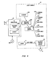
Fig. 4 is a function block diagram illustrating the control in scanning architecture of the customized ablation system ofFig. 1 . -
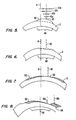
Figs. 5 through 8 schematically illustrate the use of off-center refractive ablation profiles for treatment of corneal irregularities. -
Fig. 9 is a flowchart illustrating steps for treatment of a cornea irregularity using offset ablation profiles. -
Fig. 10 illustrates therapy profiles and scale parameters included within an exemplary library. -
Figs. 11A and B illustrate data entry screens for selecting, offsetting, scaling, and combining standard ablation profiles to treat corneal irregularities. -
Figs. 12A through C schematically illustrate alternative maps for planning a custom combined ablation. -
Fig. 13 illustrates information displayed for planning and simulating a combined ablation to verify the proposed combination of ablation profiles prior to treatment of the eye. - Referring now to
Fig. 1 , asystem 10 for treatment of corneal irregularities directs alaser beam 12 from alaser 14 to an eye E having a cornea C. A pupil P has a center defining an optical axis A. - An
optical train 16 variably directslaser beam 12 onto the surface of cornea C according to a treatment profile. Rather than treating cornea C with a profile centered about axis A, an operator designates atreatment center 18 which is offset laterally (often described as the X-Y plane) from the center of pupil P. - The operator designates
treatment center 18 using aninput 20 coupled tocontroller 22, the input here schematically illustrated as a joystick. The orientation of eye E is stabilized by the patient viewing afixation target 24 throughalignment optics 26. The operator will often direct the ablation procedure while viewing eye E through amicroscope 28. - Referring now to
Fig. 2 ,laser delivery optics 16 for directinglaser beam 12 at eye E will often include a number ofmirrors 30, as well as one or more integrators 32 which may even (or otherwise tailor) the energy distribution across the laser beam.Laser 14 will often comprise an excimer laser or a suitably frequency multiplied solid state laser generating laser energy having a frequency suitable for corneal tissue ablation with minimal thermal damage to the underlying tissue. The laser system may include, but is not limited to, excimer lasers such as argon-fluoride excimer lasers (producing laser energy with a wavelength of about 193 nm), solid state lasers, including frequency multiplied solid state lasers such as flash-lamp and diode pumped solid state lasers. Exemplary solid state lasers include UV solid state lasers (approximately 193-215 nm) such as those disclosed inU.S. Patent Nos. 5,144,630 and5,742,626, Borsuztky et al. , "Tunable UV Radiation at Short Wavelengths (188-240 nm) Generated by Sum Frequency Mixing in Lithium Borate", Appl. Phys. 61:529-532 (1995), and the like. The laser energy may comprise a beam formed as a series of discreet laser pulses. A variety of alternative lasers might also be used. - In the exemplary embodiment, a
variable aperture 34 changes a diameter and/or slot width to profilelaser beam 12, ideally including both a variable diameter iris and a variable width slot. Aprism 36 separateslaser beam 12 into a plurality of beamlets, which may partially overlap on eye E to smooth edges of the ablation or "crater" from each pulse of the laser beam. Referring now toFigs. 2 and 3 , an offsetmodule 38 includesmotors 40 which vary an angular offset of an offsetlens 42, and which also change the radial orientation of the offset. Hence, offsetmodule 38 can selectively directlaser beam 12 at a desired lateral region of the cornea. A structure and method for usingoptical train 16 and offsetmodule 38 are more fully described inU.S. Patent No. 6,203,539 , entitled "Method and System for Laser Treatment of Refractive Errors Using Offset Imaging" andU.S. Patent No. 6,331,177 , entitled "Multiple Beam Laser Sculpting System and Method". - Referring now to
Fig. 4 , elements of a VISX Star S2™ excimer laser system, as commercially available from VISX, Incorporated of Santa Clara, California, are schematically illustrated as modified for use according to the principles of the present invention. Acomputer control system 22 enables precise control oflaser system 10 to sculpt a surface shape specified in a laser treatment table 302. Acontroller 22, which generally comprises a PC workstation, makes use of a computer program stored on atangible media 304 to generate treatment table 302. An embeddedcomputer 308 withinlaser system 10 is in electronic communication with the PC workstation, and may thereby comprise a portion of the overall controller. Alternatively, a PC workstation may be embedded in the laser system and function as both the embedded computer and PC workstation for directing the ophthalmic surgery. - Embedded
computer 308 is in electronic communication with a plurality ofsensors 306 and a plurality ofmotor drivers 310. The motor drivers are coupled to the controller to vary the position and configuration of many of the optical components of thedelivery optics 16 according to treatment table 302. For example, first andsecond scanning axis Iris motor 340 controls the diameter of the overall beam, and in some cases, the length of light transmitted through a variable width slot. Similarly slot width driver 350 controls the width of the variable slot.Slot angle driver 360 controls rotation of the slot about its axis.Beam angle driver 370 controls rotation of the beam, whilelaser 14 is pulsed to generate thelaser beam 12 after the various optical elements have been positioned to create a desired crater on eye E. Treatment table 302 may comprise a listing of all of the desired craters to be combined so as to effect a treatment therapy. - For customizing ablations to treat irregular corneas,
controller 22 will preferably includelibrary 44 having a number of different photorefractive and/or phototherapeutic ablation profiles. These ablation profiles will often be used for treatment of spherical and/or cylindrical refractive errors of the eye by coaxially locatingtreatment center 18 at the center of pupil P. To treat irregular corneas, these same ablation profiles may be directed to laterally offsettreatment center 18 usinginput device 20. Conveniently, the controller can modify the treatment table to offset the ablation profile by adjusting each ablation coordinate with the desired offset. - While the
input device 20 is here schematically illustrated as a joystick, it should be understood that a variety of input mechanisms may be used. Suitable offset input mechanisms may include trackballs, touch screens, or a wide variety of alternative pointing devices. Still further alternative input mechanisms include keypads, data transmission mechanisms such as an ethernet, intranet, internet, a modem, or the like. These or other input mechanisms may be used to identify an offsettreatment center 18 which is offset laterally from the center of the pupil of the eye. - The use of standard ablation profiles to treat an irregular cornea can be understood with reference to
Figs. 5 through 8 . Cornea C in Fig. 6A features a protrudingirregularity 46 of corneal tissue which is offset laterally from the optical axis A. To treat this condition, a series of laser pulses (schematically illustrated as pulses 12a-d) of gradually varying size are directed over atreatment region 48 which is centered at offsettreatment center 18. Such gradually varying diameter pulse patterns could be applied coaxially with the optical axis to flatten a central portion of the cornea and treat myopia. However, by offsetting this same treatment profile laterally, protrudingcorneal tissue 46 may be ablated so as to resculpt the cornea to a more spherical shape, as illustrated inFig. 6 . - Alternative standard photorefractive therapies may also be applied, as illustrated in
Fig. 7 . Cornea C here initially has aflat region 50 having insufficient curvature. Ahyperopia ablation profile 52, which is most often used to increase the curvature of the central cornea, is here offset laterally so as to be centered at offsetcenter 18 so as to increase the curvature of the corneal surface aboutflat region 50. - Treatment of a previously decentered ablation is schematically illustrated in
Fig. 8 using first ahyperopia ablation profile 52 centered at offset treatment center 18a, followed by amyopia ablation profile 54 center at another offsettreatment center 18b so as to decrease the irregularity of the cornea throughout an optically usedregion 56. It should be understood that the examples illustrated inFigs. 6A through 8 are schematic, that the offset treatment center may be offset in both X and Y directions, and that the multiple treatment centers will often be radially offset from each other. Additionally, it should be understood that the refractive treatment profiles will often be scaled in size and power. Algorithms and techniques for generating the therapeutic ablation profiles by combining individual ablation pulse craters are described in the patent literature listed hereinabove. - A
flow chart 60 illustrating the individual steps for developing a custom ablation strategy is illustrated inFig. 9 . Preferably, a map of the cornea will be prepared 62 using any of a wide variety of commercially available ophthalmic measurement techniques. Particularly advantageous topography measurements may be available using wavefront technology now being developed. As described hereinbelow, corneal maps based on the axial curvature or tangential curvature of the cornea may also be used independently, and/or these maps may be combined to back calculate micron elevation data. - Based on the
corneal map 62, a standard ablation profile is selected 64 with a proposed scale and offset 66. Where only a single ablation profile may be sufficient, the proposed ablation may then be simulated 68, with the resulting corneal characteristics presented to verify the proposed ablation parameters. In many cases, one or more additional ablation profiles may be added 70, or where appropriate, deleted from a previous ablation plan before the total ablation procedure is simulated. If theablation simulation 68 indicates further refinement in the ablation plan would be beneficial, the plan may be revised by adding and/or subtracting ablation profiles, varying the offset and scale of individual ablation profiles, or the like. If nofurther revision 72 is desired, the combined profile ablation plan may be implemented to ablate thecornea 74. - An exemplary library of myopic, hyperopic, and therapeutic ablation profiles is listed in
Fig. 10 . The standard ablation profiles may be scaled in both dimensions and power, with the maximum and minimum scaling parameters being as listed. In general, photorefractive profiles refer to both myopic profiles (or surfaces) and hyperopic profiles (or surfaces) as listed, while therapeutic ablation profiles refer to the corresponding shapes listed below the "therapeutic surface" heading. - The exemplary data input screens for selection of ablation profiles, designating offsets and scales, and adding or subtracting profiles are illustrated in
Figs. 11A and 11B . As illustrated inFig. 11A , a plurality of ablations may be entered for sequential and/or simultaneous ablation with individually designated offsets and scaling. Entry of the parameters for a particular ablation profile such as theoffsets 80,size 82, andpower 84 may be performed using a standard Windows™-type data entry system including a mouse or other pointing device and/or a keyboard. - Referring now to
Figs. 12A through C , elevation maps are particularly advantageous for generating the desired ablation plan, as they accurately indicate shape, location, depth, and size or irregular corneal features, as illustrated inFig. 12A . While axial curvature maps (as illustrated inFig. 12B ) provide good power values, they can be less accurate regarding the location and size of irregularities. Tangential maps such as that illustrated inFig. 12C provide good location and size information, but may be less accurate regarding specific power values. Advantageously, axial and tangential maps can be combined so as to "back calculate" elevation data, thereby significantly facilitating the planning of a custom ablation profile. - Advantageously, a proposed ablation plan may be entered into the computer based on a visual review of the corneal map. The plan may be tailored to treat asymmetrical astigmatism, inferior corneal steepening, corneal dystrophy, decentered ablations, errors inadvertently induced by prior refractive procedures, or a wide variety of other corneal irregularities. Proposed treatments may be generated to generally improved uncorrected visual acuity and/or optimize best corrected visual acuity for a particular patient. More generally, the tailored plan may enhance the overall quality of vision and reduce visual aberrations caused by irregularities.
- Advantageously, it is not necessary to link a topography system directly to an ablation system or ablation algorithm for generation of a treatment plan. Individual ablation profile settings and combinations may be controlled by the system operator, thereby providing near-term capabilities for patient's suffering from these visual defects. Alternatively, it may be advantageous to eventually link the topography information directly to the ablation profile planning computer. Hence, the selection, offset, and scaling of the ablation profiles may be performed either manually and/or automatically. Regardless, the corneal map and specific ablation mechanism may employ a variety of different structures within the scope of the present invention.
- Referring now to
Fig. 13 , after (or optionally during) selection and scaling of the individual ablation profiles based on acorneal map 90, the computer may mathematically simulate the total ablation to determine a change in thecorneal map 92 and a resulting simulatedablated cornea 94, before actually removing corneal tissue. This allows the physician or other system operator to compare before and after maps of the cornea so as to visualize the results, and to investigate a variety of alternative treatment plans prior to the actual ablation. - While the exemplary embodiment has been described in some detail, by way of example and for clarity of understanding, a variety of adaptations, changes, and modifications will be obvious to those of skill in the art. Hence, the scope of the present invention is limited solely by the appended claims.
Claims (14)
- A system for treating an eye of a patient, the eye having a cornea and a pupil, the pupil having a centre, the system comprising:a laser producing a laser beam capable of ablating the cornea;delivery optics coupled to the laser;alignment optics aligned with the delivery optics for maintaining alignment between the laser and the pupil of the eye;a library of therapy profiles which would, when centred on the eye, be suitable for treatment of a standard refractive error such as myopia, hyperopia and symmetrical cylindrical astigmatism; anda controller operable to direct the optics to effect a treatment profile centred about the treatment centre laterally offset from the centre of the pupil and selected from the library of profiles so as to aspherically resculpt the cornea about the centre of the pupil to reduce refractive errors resulting from corneal irregularities.
- The system of Claim 1, wherein the library includes a myopic treatment profile, a hyperopic treatment profile, and a cylindrical astigmatism treatment profile.
- The system of Claim 2, wherein the library further includes:myopic profiles which are spherical, cylindrical, and/or elliptical;hyperopic profiles which are spherical, cylindrical, and/or provide smooth transition zones; and/ortherapeutic profiles such as phototherapeutic keratectomy slits and/or phototherapeutic keratectomy circles of variable sizes and having variable transition zones.
- The system of Claim 1, 2 or 3, wherein the controller is operable to select and/or scale profiles from the library individually or in combination.
- A computer program or computer program product for controlling a laser for use in a method for treating an eye of a patient, the eye having a cornea and a pupil, the pupil having a centre, and comprising computer program instructions to:align a laser delivery system with the pupil of the eye;designate a treatment centre on the cornea, the treatment centre being offset laterally from the centre of the pupil; andablate a region of the cornea centred about the treatment centre by directing laser energy from the aligned laser delivery system according to a therapy profile selected from a library of profiles which would, when centred on the eye, be suitable for treatment of a standard refractive error such as myopia, hyperopia and symmetrical cylindrical astigmatism, so as to aspherically resculpt the cornea about the centre of the pupil to reduce refractive errors resulting from corneal irregularities.
- A computer program or computer program product according to Claim 5, further comprising computer program instructions to select the therapy profile from a library including a myopic treatment profile, a hyperopic treatment profile, and a cylindrical astigmatism treatment profile, the library preferably further including:myopic profiles which are spherical, cylindrical, and/or elliptical;hyperopic profiles which are spherical, cylindrical, and/or provide smooth transition zones; and/ortherapeutic profiles such as phototherapeutic keratectomy slits and/or phototherapeutic keratectomy circles of variable sizes and having variable transition zones.
- A computer program or computer program product according to Claim 5 or 6, further comprising computer program instructions to scale the profile from the library.
- A computer program or computer program product according to Claim 5, 6 or 7, further comprising computer program instructions to:select another therapy profile from the library therapies;designate another treatment centre on the cornea, the other treatment centre being offset from the treatment centre and from the centre of the pupil;scale the therapy profile and the other therapy profile; andablate another region of the cornea with the other therapy profile centred about the other treatment centre so that the therapy profiles of the ablated regions are offset from each other and from the centre of the pupil.
- A computer program or computer program product according to Claim 5 wherein the computer program instructions for resculpting comprise computer program instructions to decrease a curvature of the cornea adjacent the treatment centre according to a myopic ablation profile.
- A computer program or computer program product according to either of Claims 5 or 9 wherein the computer program instructions for resculpting comprise computer program instructions to increase a curvature of the cornea adjacent the treatment centre according to a hyperopic ablation profile.
- A computer program or computer program product according to Claim 5, wherein the computer program instructions for ablating comprise computer program instructions to mitigate a refractive error inadvertently produced by a prior treatment to the eye.
- A computer program or computer program product according to Claim 11, wherein the prior treatment comprises a prior ablation.
- A computer program or computer program product according to Claim 12, wherein the prior ablation was inadvertently offset laterally from the centre of the pupil.
- A computer program or computer program product according to Claim 5, wherein the computer program instructions for ablating comprise computer program instructions to mitigate a refractive error of the eye selected from the group consisting of irregular astigmatism, corneal steepening in one quadrant, and asymmetrical astigmatism and/or further comprising computer program instructions to:measure the eye to generate a map of the eye;select the therapy profile in response to the map from the library; andselect the offset in response to the map so as to mitigate an irregular refractive error of the eye.
Applications Claiming Priority (3)
| Application Number | Priority Date | Filing Date | Title |
|---|---|---|---|
| US09/287,322 US6245059B1 (en) | 1999-04-07 | 1999-04-07 | Offset ablation profiles for treatment of irregular astigmation |
| US287322 | 1999-04-07 | ||
| PCT/US2000/005382 WO2000059395A1 (en) | 1999-04-07 | 2000-02-28 | Offset ablation profiles for treatment of irregular astigmatism |
Publications (3)
| Publication Number | Publication Date |
|---|---|
| EP1173104A1 EP1173104A1 (en) | 2002-01-23 |
| EP1173104A4 EP1173104A4 (en) | 2006-02-01 |
| EP1173104B1 true EP1173104B1 (en) | 2011-07-20 |
Family
ID=23102398
Family Applications (1)
| Application Number | Title | Priority Date | Filing Date |
|---|---|---|---|
| EP00914794A Expired - Lifetime EP1173104B1 (en) | 1999-04-07 | 2000-02-28 | Offset ablation profiles for treatment of irregular astigmatism |
Country Status (7)
| Country | Link |
|---|---|
| US (3) | US6245059B1 (en) |
| EP (1) | EP1173104B1 (en) |
| JP (1) | JP3615487B2 (en) |
| AT (1) | ATE516785T1 (en) |
| AU (1) | AU3613800A (en) |
| CA (1) | CA2361834C (en) |
| WO (1) | WO2000059395A1 (en) |
Families Citing this family (60)
| Publication number | Priority date | Publication date | Assignee | Title |
|---|---|---|---|---|
| CA2306864C (en) * | 1998-03-04 | 2012-05-15 | Visx, Incorporated | Systems for laser treatment of presbyopia using offset imaging |
| US6245059B1 (en) * | 1999-04-07 | 2001-06-12 | Visx, Incorporated | Offset ablation profiles for treatment of irregular astigmation |
| US6488676B1 (en) * | 1999-09-24 | 2002-12-03 | Visx, Incorporated | Two-pivot scanning for laser eye surgery |
| US6673062B2 (en) * | 2000-03-14 | 2004-01-06 | Visx, Inc. | Generating scanning spot locations for laser eye surgery |
| US6584343B1 (en) * | 2000-03-15 | 2003-06-24 | Resolution Medical, Inc. | Multi-electrode panel system for sensing electrical activity of the heart |
| US7044944B2 (en) * | 2000-03-22 | 2006-05-16 | Alcon Refractivehorizons, Inc. | Optimization of ablation correction of an optical system and associated methods |
| US7044602B2 (en) | 2002-05-30 | 2006-05-16 | Visx, Incorporated | Methods and systems for tracking a torsional orientation and position of an eye |
| JP2003532484A (en) * | 2000-05-09 | 2003-11-05 | メンフィス アイ アンド カタラクト アソシエーツ アンビュラトリー サージェリー センター(ディー.ビー.エー.)メカ レーザー アンド サージェリー センター | Method and apparatus for controlling a high resolution high speed digital micromirror device for laser refractive ophthalmic surgery |
| DE10022995C2 (en) * | 2000-05-11 | 2003-11-27 | Wavelight Laser Technologie Ag | Device for photorefractive corneal surgery |
| IT1318699B1 (en) * | 2000-09-15 | 2003-08-27 | Ligi Tecnologie Medicali S R L | EQUIPMENT TO DETERMINE AND ABLATE THE VOLUME OF THE CORNEAL TISSUE NECESSARY TO CARRY OUT A CORNEA LAMELLAR TRANSPLANT. |
| US6561648B2 (en) * | 2001-05-23 | 2003-05-13 | David E. Thomas | System and method for reconstruction of aberrated wavefronts |
| US6827442B2 (en) * | 2001-09-12 | 2004-12-07 | Denwood F. Ross | Ophthalmic wavefront measuring devices |
| EP1435866A2 (en) * | 2001-10-18 | 2004-07-14 | The Cleveland Clinic Foundation | Systems and methods for analysis of corneal topography with convexity map |
| AU2003216240A1 (en) * | 2002-02-11 | 2003-09-04 | Visx, Inc. | Closed loop system and method for ablating lenses with aberrations |
| US20040002740A1 (en) * | 2002-05-08 | 2004-01-01 | The Regents Of The University Of California | System and method for forming a non-ablative cardiac conduction block |
| US20040106896A1 (en) * | 2002-11-29 | 2004-06-03 | The Regents Of The University Of California | System and method for forming a non-ablative cardiac conduction block |
| US7077838B2 (en) | 2002-05-30 | 2006-07-18 | Visx, Incorporated | Variable repetition rate firing scheme for refractive laser systems |
| US6964659B2 (en) | 2002-05-30 | 2005-11-15 | Visx, Incorporated | Thermal modeling for reduction of refractive laser surgery times |
| JP2005527325A (en) | 2002-05-31 | 2005-09-15 | カール ツアイス メディテック アクチエンゲゼルシャフト | Apparatus for treating human eye and control method of ablation apparatus |
| US7083609B2 (en) * | 2002-06-13 | 2006-08-01 | Visx, Incorporated | Corneal topography-based target warping |
| US7317950B2 (en) * | 2002-11-16 | 2008-01-08 | The Regents Of The University Of California | Cardiac stimulation system with delivery of conductive agent |
| US6932808B2 (en) * | 2002-11-19 | 2005-08-23 | Visx, Incorporated | Ablation shape for the correction of presbyopia |
| US8968279B2 (en) * | 2003-03-06 | 2015-03-03 | Amo Manufacturing Usa, Llc | Systems and methods for qualifying and calibrating a beam delivery system |
| EP1617751B1 (en) * | 2003-04-09 | 2016-05-04 | AMO Manufacturing USA, LLC | Wavefront calibration analyzer and methods |
| MXPA05011131A (en) * | 2003-04-18 | 2006-03-10 | Visx Inc | Systems and methods for correcting high order aberrations in laser refractive surgery. |
| US7458683B2 (en) | 2003-06-16 | 2008-12-02 | Amo Manufacturing Usa, Llc | Methods and devices for registering optical measurement datasets of an optical system |
| US7226443B1 (en) | 2003-11-07 | 2007-06-05 | Alcon Refractivehorizons, Inc. | Optimization of ablation correction of an optical system and associated methods |
| US7481536B2 (en) * | 2004-02-19 | 2009-01-27 | Amo Manufacturing Usa, Llc | Methods and systems for differentiating left and right eye images |
| AU2005222863C1 (en) * | 2004-03-15 | 2010-07-22 | Visx, Incorporated | Stabilizing delivered laser energy |
| US20070027438A1 (en) * | 2005-07-26 | 2007-02-01 | Frieder Loesel | System and method for compensating a corneal dissection |
| AU2006312148B2 (en) * | 2005-11-07 | 2012-04-12 | The Rockefeller University | Reagents, methods and systems for selecting a cytotoxic antibody or variant thereof |
| US7811280B2 (en) * | 2006-01-26 | 2010-10-12 | Amo Manufacturing Usa, Llc. | System and method for laser ablation calibration |
| US8518030B2 (en) * | 2006-03-10 | 2013-08-27 | Amo Manufacturing Usa, Llc | Output energy control for lasers |
| AU2012261645B2 (en) * | 2006-10-16 | 2016-01-14 | Carl Zeiss Meditec, Inc. | Ocular radiosurgery |
| AU2016201833B2 (en) * | 2006-10-16 | 2017-09-28 | Carl Zeiss Meditec, Inc. | Ocular radiosurgery |
| US7496174B2 (en) | 2006-10-16 | 2009-02-24 | Oraya Therapeutics, Inc. | Portable orthovoltage radiotherapy |
| US7620147B2 (en) * | 2006-12-13 | 2009-11-17 | Oraya Therapeutics, Inc. | Orthovoltage radiotherapy |
| US8926600B2 (en) * | 2006-11-10 | 2015-01-06 | Amo Manufacturing Usa, Llc | Operator-controlled scanning laser procedure designed for large-area epithelium removal |
| US7931644B2 (en) * | 2006-11-10 | 2011-04-26 | Amo Development Llc. | Operator-controlled scanning laser procedure designed for large-area epithelium removal |
| AU2015200832B2 (en) * | 2007-03-13 | 2018-02-22 | Amo Development, Llc | Apparatus for creating ocular surgical and relaxing incisions |
| CN101631522B (en) | 2007-03-13 | 2014-11-05 | 眼科医疗公司 | Apparatus for creating ocular surgical and relaxing incisions |
| TWI407971B (en) * | 2007-03-30 | 2013-09-11 | Nitto Denko Corp | Cancer cells and tumor-related fibroblasts |
| US9295584B2 (en) * | 2007-05-17 | 2016-03-29 | Amo Development, Llc | Customized laser epithelial ablation systems and methods |
| US8920406B2 (en) * | 2008-01-11 | 2014-12-30 | Oraya Therapeutics, Inc. | Device and assembly for positioning and stabilizing an eye |
| US8363783B2 (en) | 2007-06-04 | 2013-01-29 | Oraya Therapeutics, Inc. | Method and device for ocular alignment and coupling of ocular structures |
| EP3272395B1 (en) | 2007-12-23 | 2019-07-17 | Carl Zeiss Meditec, Inc. | Devices for detecting, controlling, and predicting radiation delivery |
| US7801271B2 (en) | 2007-12-23 | 2010-09-21 | Oraya Therapeutics, Inc. | Methods and devices for orthovoltage ocular radiotherapy and treatment planning |
| WO2010052596A1 (en) * | 2008-11-04 | 2010-05-14 | Koninklijke Philips Electronics, N.V. | Method and system for ultrasound therapy |
| US8444632B2 (en) * | 2008-11-05 | 2013-05-21 | Carl Zeiss Meditec Ag | Method of performing refractive laser eye surgery centered along the visual axis of a human eye |
| US8366701B2 (en) * | 2009-01-27 | 2013-02-05 | Technolas Perfect Vision Gmbh | System and method for correcting higher order aberrations with changes in intrastromal biomechanical stress distributions |
| US9642518B2 (en) | 2010-03-30 | 2017-05-09 | Amo Development, Llc | Random eye generation systems and methods |
| US8409178B2 (en) | 2010-03-30 | 2013-04-02 | Amo Development Llc. | Systems and methods for evaluating treatment tables for refractive surgery |
| EP2598082A4 (en) | 2010-07-26 | 2017-01-25 | Vision Crc Limited | Treating ocular refractive error |
| US9501621B2 (en) | 2011-03-18 | 2016-11-22 | Amo Development, Llc | Treatment validation systems and methods |
| WO2013082466A1 (en) | 2011-11-30 | 2013-06-06 | Amo Development, Llc. | System and method for ophthalmic surface measurements based on sequential estimates |
| JP5890582B2 (en) * | 2012-04-20 | 2016-03-22 | バーフェリヒト ゲゼルシャフト ミット ベシュレンクテル ハフツング | Apparatus, method and computer program for control of corneal ablation laser |
| JP6236882B2 (en) * | 2013-06-03 | 2017-11-29 | 株式会社ニデック | Laser therapy device |
| US20180042771A1 (en) | 2016-08-10 | 2018-02-15 | Amo Development, Llc | Epithelial ablation systems and methods |
| CN110662580B (en) * | 2017-05-31 | 2021-11-09 | 帝人制药株式会社 | Light therapy device |
| EP3638165B1 (en) * | 2017-06-15 | 2021-07-21 | Alcon Inc. | Birefringent lens for laser beam delivery |
Family Cites Families (26)
| Publication number | Priority date | Publication date | Assignee | Title |
|---|---|---|---|---|
| US4724522A (en) | 1986-05-27 | 1988-02-09 | Belgorod Barry M | Method and apparatus for modification of corneal refractive properties |
| US5098426A (en) | 1989-02-06 | 1992-03-24 | Phoenix Laser Systems, Inc. | Method and apparatus for precision laser surgery |
| US5779696A (en) * | 1990-07-23 | 1998-07-14 | Sunrise Technologies International, Inc. | Method and apparatus for performing corneal reshaping to correct ocular refractive errors |
| JP3168207B2 (en) | 1990-08-22 | 2001-05-21 | ヴィスクス・インコーポレイテッド | Surgical laser beam scanning device |
| IT1242932B (en) | 1990-11-14 | 1994-05-18 | Guido Maria Nizzola | PRESBYOPIA CORRECTION EQUIPMENT BY MODELING THE CORNEAL SURFACE FOR PHOTO ABLATION |
| US5984916A (en) * | 1993-04-20 | 1999-11-16 | Lai; Shui T. | Ophthalmic surgical laser and method |
| US5637109A (en) | 1992-02-14 | 1997-06-10 | Nidek Co., Ltd. | Apparatus for operation on a cornea using laser-beam |
| US5439462A (en) | 1992-02-25 | 1995-08-08 | Intelligent Surgical Lasers | Apparatus for removing cataractous material |
| US5290272A (en) | 1992-03-16 | 1994-03-01 | Helios Inc. | Method for the joining of ocular tissues using laser light |
| DE4232915A1 (en) | 1992-10-01 | 1994-04-07 | Hohla Kristian | Device for shaping the cornea by removing tissue |
| US5437658A (en) * | 1992-10-07 | 1995-08-01 | Summit Technology, Incorporated | Method and system for laser thermokeratoplasty of the cornea |
| US5634919A (en) | 1993-02-22 | 1997-06-03 | The Johns Hopkins University | Correction of strabismus by laser-sculpturing of the cornea |
| US5556395A (en) | 1993-05-07 | 1996-09-17 | Visx Incorporated | Method and system for laser treatment of refractive error using an offset image of a rotatable mask |
| CO4230054A1 (en) | 1993-05-07 | 1995-10-19 | Visx Inc | METHOD AND SYSTEMS FOR LASER TREATMENT OF REFRACTIVE ERRORS USING TRAVELING IMAGES FORMATION |
| US5549597A (en) | 1993-05-07 | 1996-08-27 | Visx Incorporated | In situ astigmatism axis alignment |
| US5549596A (en) | 1993-07-07 | 1996-08-27 | The General Hospital Corporation | Selective laser targeting of pigmented ocular cells |
| CA2187373C (en) | 1994-04-08 | 2001-06-05 | Kristian Hohla | Method and apparatus for providing precise location of points on the eye |
| US5980513A (en) * | 1994-04-25 | 1999-11-09 | Autonomous Technologies Corp. | Laser beam delivery and eye tracking system |
| US5752967A (en) * | 1995-07-27 | 1998-05-19 | Kritzinger; Michiel S. | Corneal surface marker and marking method for improving laser centration |
| US6299307B1 (en) * | 1997-10-10 | 2001-10-09 | Visx, Incorporated | Eye tracking device for laser eye surgery using corneal margin detection |
| CA2306864C (en) * | 1998-03-04 | 2012-05-15 | Visx, Incorporated | Systems for laser treatment of presbyopia using offset imaging |
| US6331177B1 (en) * | 1998-04-17 | 2001-12-18 | Visx, Incorporated | Multiple beam laser sculpting system and method |
| US6245059B1 (en) | 1999-04-07 | 2001-06-12 | Visx, Incorporated | Offset ablation profiles for treatment of irregular astigmation |
| US6673062B2 (en) * | 2000-03-14 | 2004-01-06 | Visx, Inc. | Generating scanning spot locations for laser eye surgery |
| DE10022995C2 (en) * | 2000-05-11 | 2003-11-27 | Wavelight Laser Technologie Ag | Device for photorefractive corneal surgery |
| US6864478B2 (en) * | 2002-04-22 | 2005-03-08 | Visx, Incorporation | Beam position monitoring for laser eye surgery |
-
1999
- 1999-04-07 US US09/287,322 patent/US6245059B1/en not_active Expired - Lifetime
-
2000
- 2000-02-28 WO PCT/US2000/005382 patent/WO2000059395A1/en active Application Filing
- 2000-02-28 AT AT00914794T patent/ATE516785T1/en not_active IP Right Cessation
- 2000-02-28 CA CA002361834A patent/CA2361834C/en not_active Expired - Lifetime
- 2000-02-28 EP EP00914794A patent/EP1173104B1/en not_active Expired - Lifetime
- 2000-02-28 AU AU36138/00A patent/AU3613800A/en not_active Abandoned
- 2000-02-28 JP JP2000608962A patent/JP3615487B2/en not_active Expired - Fee Related
-
2001
- 2001-03-29 US US09/823,416 patent/US6572607B2/en not_active Expired - Lifetime
-
2003
- 2003-03-27 US US10/402,478 patent/US7004935B2/en not_active Expired - Lifetime
Also Published As
| Publication number | Publication date |
|---|---|
| US20010020163A1 (en) | 2001-09-06 |
| JP3615487B2 (en) | 2005-02-02 |
| CA2361834C (en) | 2009-02-24 |
| WO2000059395A1 (en) | 2000-10-12 |
| ATE516785T1 (en) | 2011-08-15 |
| EP1173104A4 (en) | 2006-02-01 |
| WO2000059395A9 (en) | 2002-03-14 |
| US7004935B2 (en) | 2006-02-28 |
| US6572607B2 (en) | 2003-06-03 |
| JP2002540837A (en) | 2002-12-03 |
| EP1173104A1 (en) | 2002-01-23 |
| CA2361834A1 (en) | 2000-10-12 |
| AU3613800A (en) | 2000-10-23 |
| US6245059B1 (en) | 2001-06-12 |
| US20030220631A1 (en) | 2003-11-27 |
Similar Documents
| Publication | Publication Date | Title |
|---|---|---|
| EP1173104B1 (en) | Offset ablation profiles for treatment of irregular astigmatism | |
| EP1534161B1 (en) | Corneal topography-based target warping | |
| CA2485692C (en) | Variable repetition rate firing scheme for refractive laser systems | |
| EP1645222B1 (en) | Ophthalmologic surgery system | |
| US6394999B1 (en) | Laser eye surgery system using wavefront sensor analysis to control digital micromirror device (DMD) mirror patterns | |
| EP0529822B1 (en) | Apparatus for combined cylindrical and spherical eye corrections | |
| JP4516756B2 (en) | Blend region and transition region for cornea removal | |
| AU2001239761A1 (en) | Laser eye surgery system using wavefront sensor analysis to control digital micromirror device (DMD) mirror patterns | |
| US20020097375A1 (en) | Enhanced wavefront ablation system | |
| EP2785294B1 (en) | System and method for ophthalmic surface measurements based on sequential estimates | |
| US10783999B2 (en) | Basis data evaluation systems and methods | |
| MXPA01010027A (en) | Offset ablation profiles for treatment of irregular astigmatism |
Legal Events
| Date | Code | Title | Description |
|---|---|---|---|
| PUAI | Public reference made under article 153(3) epc to a published international application that has entered the european phase |
Free format text: ORIGINAL CODE: 0009012 |
|
| 17P | Request for examination filed |
Effective date: 20011004 |
|
| AK | Designated contracting states |
Kind code of ref document: A1 Designated state(s): AT BE CH CY DE DK ES FI FR GB GR IE IT LI LU MC NL PT SE |
|
| AX | Request for extension of the european patent |
Free format text: AL;LT;LV;MK;RO;SI |
|
| RIC1 | Information provided on ipc code assigned before grant |
Ipc: 7A 61F 9/01 A Ipc: 7A 61B 18/18 B |
|
| A4 | Supplementary search report drawn up and despatched |
Effective date: 20051219 |
|
| RAP1 | Party data changed (applicant data changed or rights of an application transferred) |
Owner name: AMO MANUFACTURING USA, LLC |
|
| RAP1 | Party data changed (applicant data changed or rights of an application transferred) |
Owner name: AMO MANUFACTURING USA, LLC |
|
| GRAP | Despatch of communication of intention to grant a patent |
Free format text: ORIGINAL CODE: EPIDOSNIGR1 |
|
| GRAS | Grant fee paid |
Free format text: ORIGINAL CODE: EPIDOSNIGR3 |
|
| GRAA | (expected) grant |
Free format text: ORIGINAL CODE: 0009210 |
|
| AK | Designated contracting states |
Kind code of ref document: B1 Designated state(s): AT BE CH CY DE DK ES FI FR GB GR IE IT LI LU MC NL PT SE |
|
| REG | Reference to a national code |
Ref country code: GB Ref legal event code: FG4D |
|
| REG | Reference to a national code |
Ref country code: CH Ref legal event code: EP Ref country code: CH Ref legal event code: NV Representative=s name: RENTSCH PARTNER AG |
|
| REG | Reference to a national code |
Ref country code: NL Ref legal event code: T3 |
|
| REG | Reference to a national code |
Ref country code: DE Ref legal event code: R096 Ref document number: 60046232 Country of ref document: DE Effective date: 20110908 |
|
| REG | Reference to a national code |
Ref country code: AT Ref legal event code: MK05 Ref document number: 516785 Country of ref document: AT Kind code of ref document: T Effective date: 20110720 |
|
| PG25 | Lapsed in a contracting state [announced via postgrant information from national office to epo] |
Ref country code: PT Free format text: LAPSE BECAUSE OF FAILURE TO SUBMIT A TRANSLATION OF THE DESCRIPTION OR TO PAY THE FEE WITHIN THE PRESCRIBED TIME-LIMIT Effective date: 20111121 Ref country code: BE Free format text: LAPSE BECAUSE OF FAILURE TO SUBMIT A TRANSLATION OF THE DESCRIPTION OR TO PAY THE FEE WITHIN THE PRESCRIBED TIME-LIMIT Effective date: 20110720 Ref country code: FI Free format text: LAPSE BECAUSE OF FAILURE TO SUBMIT A TRANSLATION OF THE DESCRIPTION OR TO PAY THE FEE WITHIN THE PRESCRIBED TIME-LIMIT Effective date: 20110720 Ref country code: SE Free format text: LAPSE BECAUSE OF FAILURE TO SUBMIT A TRANSLATION OF THE DESCRIPTION OR TO PAY THE FEE WITHIN THE PRESCRIBED TIME-LIMIT Effective date: 20110720 |
|
| PG25 | Lapsed in a contracting state [announced via postgrant information from national office to epo] |
Ref country code: CY Free format text: LAPSE BECAUSE OF FAILURE TO SUBMIT A TRANSLATION OF THE DESCRIPTION OR TO PAY THE FEE WITHIN THE PRESCRIBED TIME-LIMIT Effective date: 20110720 Ref country code: GR Free format text: LAPSE BECAUSE OF FAILURE TO SUBMIT A TRANSLATION OF THE DESCRIPTION OR TO PAY THE FEE WITHIN THE PRESCRIBED TIME-LIMIT Effective date: 20111021 Ref country code: AT Free format text: LAPSE BECAUSE OF FAILURE TO SUBMIT A TRANSLATION OF THE DESCRIPTION OR TO PAY THE FEE WITHIN THE PRESCRIBED TIME-LIMIT Effective date: 20110720 |
|
| PLBE | No opposition filed within time limit |
Free format text: ORIGINAL CODE: 0009261 |
|
| STAA | Information on the status of an ep patent application or granted ep patent |
Free format text: STATUS: NO OPPOSITION FILED WITHIN TIME LIMIT |
|
| PG25 | Lapsed in a contracting state [announced via postgrant information from national office to epo] |
Ref country code: IT Free format text: LAPSE BECAUSE OF FAILURE TO SUBMIT A TRANSLATION OF THE DESCRIPTION OR TO PAY THE FEE WITHIN THE PRESCRIBED TIME-LIMIT Effective date: 20110720 |
|
| 26N | No opposition filed |
Effective date: 20120423 |
|
| PG25 | Lapsed in a contracting state [announced via postgrant information from national office to epo] |
Ref country code: DK Free format text: LAPSE BECAUSE OF FAILURE TO SUBMIT A TRANSLATION OF THE DESCRIPTION OR TO PAY THE FEE WITHIN THE PRESCRIBED TIME-LIMIT Effective date: 20110720 |
|
| REG | Reference to a national code |
Ref country code: DE Ref legal event code: R097 Ref document number: 60046232 Country of ref document: DE Effective date: 20120423 |
|
| PG25 | Lapsed in a contracting state [announced via postgrant information from national office to epo] |
Ref country code: MC Free format text: LAPSE BECAUSE OF NON-PAYMENT OF DUE FEES Effective date: 20120229 |
|
| REG | Reference to a national code |
Ref country code: IE Ref legal event code: MM4A |
|
| PG25 | Lapsed in a contracting state [announced via postgrant information from national office to epo] |
Ref country code: IE Free format text: LAPSE BECAUSE OF NON-PAYMENT OF DUE FEES Effective date: 20120228 |
|
| PG25 | Lapsed in a contracting state [announced via postgrant information from national office to epo] |
Ref country code: ES Free format text: LAPSE BECAUSE OF FAILURE TO SUBMIT A TRANSLATION OF THE DESCRIPTION OR TO PAY THE FEE WITHIN THE PRESCRIBED TIME-LIMIT Effective date: 20111031 |
|
| PG25 | Lapsed in a contracting state [announced via postgrant information from national office to epo] |
Ref country code: LU Free format text: LAPSE BECAUSE OF NON-PAYMENT OF DUE FEES Effective date: 20120228 |
|
| REG | Reference to a national code |
Ref country code: FR Ref legal event code: PLFP Year of fee payment: 16 |
|
| REG | Reference to a national code |
Ref country code: FR Ref legal event code: PLFP Year of fee payment: 17 |
|
| REG | Reference to a national code |
Ref country code: FR Ref legal event code: PLFP Year of fee payment: 18 |
|
| REG | Reference to a national code |
Ref country code: CH Ref legal event code: PCAR Free format text: NEW ADDRESS: BELLERIVESTRASSE 203 POSTFACH, 8034 ZUERICH (CH) |
|
| REG | Reference to a national code |
Ref country code: FR Ref legal event code: PLFP Year of fee payment: 19 |
|
| PGFP | Annual fee paid to national office [announced via postgrant information from national office to epo] |
Ref country code: NL Payment date: 20190214 Year of fee payment: 20 |
|
| PGFP | Annual fee paid to national office [announced via postgrant information from national office to epo] |
Ref country code: DE Payment date: 20190212 Year of fee payment: 20 Ref country code: GB Payment date: 20190227 Year of fee payment: 20 Ref country code: FR Payment date: 20190111 Year of fee payment: 20 Ref country code: CH Payment date: 20190215 Year of fee payment: 20 |
|
| REG | Reference to a national code |
Ref country code: DE Ref legal event code: R071 Ref document number: 60046232 Country of ref document: DE |
|
| REG | Reference to a national code |
Ref country code: CH Ref legal event code: PL |
|
| REG | Reference to a national code |
Ref country code: GB Ref legal event code: PE20 Expiry date: 20200227 |
|
| PG25 | Lapsed in a contracting state [announced via postgrant information from national office to epo] |
Ref country code: GB Free format text: LAPSE BECAUSE OF EXPIRATION OF PROTECTION Effective date: 20200227 |
|
| REG | Reference to a national code |
Ref country code: NL Ref legal event code: MK Effective date: 20200227 |