BACKGROUND OF THE INVENTION
Field of the Invention
The present invention relates to a backlight for illuminating a transmissive liquid
crystal panel and to a liquid crystal display device having such a backlight. The present
invention relates particularly to a backlight and a liquid crystal display device that permit the
viewing of a displayed image only within a particular range of viewing angles.
Description of the Prior Art
A liquid crystal display device having a transmissive liquid crystal panel is so
structured as to produce a desired image by illuminating the liquid crystal panel from behind
with a backlight so that light is transmitted through particular pixels of the liquid crystal panel.
This permits the viewing of a displayed image even, for example, at night when no ambient
light is available.
A liquid crystal display device designed for use in a navigation system mounted on
a car, an automated teller machine (ATM) installed at a banking institution, or the like is so
configured as to permit the viewing of a displayed image only from a viewpoint within a
particular range of viewing angles so that the displayed image cannot be viewed from a
viewpoint outside that range of viewing angles. This is because, with a liquid crystal display
device for car-mounted use, the range of angles of emergence of the light emerging therefrom
is limited because, if an image displayed thereon is projected onto the windshield of the car, it
may disturb the field of vision of the driver and lead to a car accident. On the other hand,
with a liquid crystal display device for use in an ATM, the range of angles of emergence of
the light emerging therefrom is limited so that no one can view the information displayed on
the liquid crystal panel other than the one who is operating the ATM.
Fig. 26 shows the structure of a conventional liquid crystal display device that can
control the range of angles of emergence of the light emerging therefrom. The liquid crystal
display device 1 is composed essentially of a liquid crystal panel 6 and a backlight 7. The
backlight 7 has a light guide plate 3 covered with a reflector sheet 4 made of polyethylene
terephthalate (PET) foam. Along opposite sides of the light guide plate 3, light sources 2 are
supported by a supporting member (not shown). The back surface 3b of the light guide plate
3 is formed as a non-glossy surface, so that the light emitted from the light sources 2 is
incident on the light guide plate 3 and then emerges therefrom through its exit surface 3a as
scattered light.
Above the light guide plate 3 are arranged a diffuser sheet 20 for producing
diffused light and a light shield louver 5 for shielding the light incident within a
predetermined range of angles. As shown in Fig. 27, the light shield louver 5 has light-transmitting
layers 5a, which transmit light, and light-absorbing layers 5b, which absorb light,
arranged, for example, at 50 µm intervals and sandwiched between transparent base plates 5c.
Thus, of the light incident on the light shield louver 5, the portion traveling within a range
of viewing angles is transmitted, but the portion traveling outside the range of viewing
angles is shielded.
Above the light shield louver 5, a transmissive liquid crystal panel 6 is disposed.
The light traveling within the range of viewing angles (see Fig. 27) and thus transmitted
through the light shield louver 5 illuminates the liquid crystal panel 6, and is transmitted
through particular pixels thereof so as to form an image. As a result, the image can be
viewed from a viewpoint within a predetermined range of directions.
However, the conventional liquid crystal display device 1 described above, for
example when it offers a range of viewing angles of 90°, exhibits transmittance as shown in
Fig. 29. In this figure, the angle of incidence (°) with respect to the light shield louver 5 is
taken along the horizontal axis, and the transmittance (%) is taken along the vertical axis.
As this figure shows, the transmittance is highest at an angle of incidence of 0°, and the
transmittance linearly decreases as the absolute value of the angle of incidence increases.
Owing to the characteristics of the backlight 7 shown in Fig. 26, the light emerging
from the light guide plate 3 exhibits a brightness distribution as shown in Fig. 28, offering the
highest brightness around an angle of incidence of 0° with respect to the light shield louver 5.
As a result, the light transmitted through the light shield louver 5 and then incident on the
liquid crystal panel 6 exhibits a brightness distribution as shown in Fig. 30.
In Fig. 28, the angle of incidence (°) with respect to the light shield louver 5 is
taken along the horizontal axis, and the relative brightness (%) relative to the brightness
(100%) at an angle of incidence of 0° is taken along the vertical axis. In Fig. 30, the angle of
emergence (°) with respect to the light shield louver 5 is taken along the horizontal axis, and
the relative brightness (%) relative to the brightness (100%) at an angle of emergence of 0° is
taken along the vertical axis.
As Fig. 30 shows, the brightness is highest at an angle of emergence of 0°, and the
brightness falls sharply as the absolute value of the angle of emergence increases. This is
the reason that, as the viewpoint of the viewer varies according to his or her height, sitting
height, or the like, the viewability of the liquid crystal display device I degrades markedly.
Moreover, in the production of the light shield louver 5, errors are inevitable in the
intervals at which the light-transmitting layers 5a and the light-absorbing layers 5b are
arranged. As a result, as shown in Fig. 31, when the liquid crystal display device 1 is viewed
from the directions indicated by arrows P1 and P2, part of the viewer's lines of sight are
shielded by the light-absorbing layers 5b as arrow P2 indicates. This causes black stripes to
be observed by the viewer, and thus degrades the viewability of the liquid crystal display
device 1
SUMMARY OF THE INVENTION
An object of the present invention is to provide a backlight and a liquid crystal
display device that permit the viewing of a displayed image within a desired range of viewing
angles with reduced degradation of viewability.
To achieve the above object, according to one aspect of the present invention, a
backlight is provided with: a light source; a flat-plate-shaped light guide plate for guiding
the light emitted from the light source in a predetermined direction; a light shield louver,
disposed so as to face the light guide plate, for shielding part of the light emerging from the
light guide plate according to angles of incidence; and a converter for converting the
brightness distribution of the light incident on the light shield louver into a predetermined
brightness distribution. Here, the brightness distribution of the light incident on the light
shield louver is converted in such a way that the brightness at a predetermined angle of
incidence within the range from 0° to +90° and the brightness at a predetermined angle of
incidence within the range from 0° to -90° are higher than the brightness at an angle of
incidence of 0°.
In this configuration, the light emitted from the light source is guided to the light
shield louver by the light guide plate. The light incident on the light shield louver is
converted so as to have a predetermined brightness distribution by the converter before or
after the light emerges from the light guide plate. The light thus converted exhibits the
highest brightness in both the positive and negative directions relative to an angle of incidence
of 0 °, at which the brightness is lower than the highest brightness.
In the backlight configured as described above, the converter may be composed of
prisms arranged at predetermined intervals.
According to another aspect of the present invention, a backlight is provided with:
a light source; a flat-plate-shaped light guide plate for guiding the light emitted from the light
source in a predetermined direction; a light shield louver, disposed so as to face the light
guide plate, for shielding part of the light emerging from the light guide plate according to
angles of incidence; and a converter for converting the brightness distribution of the light
incident on the light shield louver into a predetermined brightness distribution. Here, the
converter shifts the average direction of incidence of the light incident on the light shield
louver from the direction normal to the light shield louver.
In this configuration, the light emitted from the light source is guided to the light
shield louver by the light guide plate. The light incident on the light shield louver is
converted so as to have a predetermined brightness distribution by the converter before or
after the light emerges from the light guide plate. The light is incident on the light shield
louver from a direction shifted from the direction normal to the light shield louver. Here, the
average direction of incidence means the direction indicated by the average of angles at which
light is incident on the light shield louver.
In the backlight configured as described above, the converter may have a Fresnel
sheet having a sawtooth-shaped section.
In the backlight configured as described above, the brightness distribution of the
light incident on the light shield louver may be converted in such a way that the brightness at
a predetermined angle of incidence in the positive direction relative to the average angle of
incidence and the brightness at a predetermined angle of incidence in the negative direction
relative to the average angle of incidence are higher than the brightness at the average angle
of incidence.
In this configuration, the light incident on the light shield louver exhibits the
highest brightness in both the positive and negative directions relative to the average angle of
incidence, at which the brightness is lower than the highest brightness. Here, the average
angle of incidence means the average of angles at which light is incident on the light shield
louver.
In the backlight configured as described above, the light source may emit varying
amounts of light according to directions of emergence. This configuration permits the
amount of light emerging from the backlight outside the desired range of angles to be reduced,
and thus helps save electric power.
According to another aspect of the present invention, a liquid crystal display
device is provided with: a backlight including a light source, a flat-plate-shaped light guide
plate for guiding the light emitted from the light source in a predetermined direction, a light
shield louver, disposed so as to face the light guide plate, for shielding part of the light
emerging from the light guide plate according to angles of incidence, and a converter for
converting the brightness distribution of the light incident on the light shield louver into a
predetermined brightness distribution; and a liquid crystal panel that displays an image by
transmitting the light emerging from the backlight. Here, the brightness distribution of the
light incident on the light shield louver is converted in such a way that the brightness at a
predetermined angle of incidence within the range from 0° to +90° and the brightness at a
predetermined angle of incidence within the range from 0° to -90° are higher than the
brightness at an angle of incidence of 0°.
According to another aspect of the present invention, a liquid crystal display
device is provided with: a backlight including a light source, a flat-plate-shaped light guide
plate for guiding the light emitted from the light source in a predetermined direction, a light
shield louver, disposed so as to face the light guide plate, for shielding part of the light
emerging from the light guide plate according to angles of incidence, and a converter for
converting the brightness distribution of the light incident on the light shield louver into a
predetermined brightness distribution; and a liquid crystal panel that displays an image by
transmitting the light emerging from the backlight. Here, the converter shifts the average
direction of incidence of the light incident on the light shield louver from the direction normal
to the light shield louver.
According to another aspect of the present invention, a liquid crystal display
device is provided with: a backlight including a light source, a flat-plate-shaped light guide
plate for guiding the light emitted from the light source in a predetermined direction, a light
shield louver, disposed so as to face the light guide plate, for shielding part of the light
emerging from the light guide plate according to angles of incidence, and a converter for
converting the brightness distribution of the light incident on the light shield louver into a
predetermined brightness distribution; and a liquid crystal panel that displays an image by
transmitting the light emerging from the backlight. Here, the converter performs conversion
in such a way that the light emerging from the light shield louver exhibits a brightness
distribution such that, assuming that the brightness at an angle of emergence of 0° is X and
the absolute value of the angle of emergence at which the brightness is 0.1X is α, the
brightness at an angle of incidence of which the absolute value is α / 2 is 0.55X or higher.
In this configuration, the light emitted from the light source is guided to the light
shield louver by the light guide plate. The light incident on the light shield louver is
converted so as to have a predetermined brightness distribution by the converter before or
after the light emerges from the light guide plate. The transmittance of the light shield
louver is highest at an angle of incidence of 0°, and linearly decreases as the angle of
incidence increases until it becomes substantially 0% at the limits of the range of viewing
angles. The light emerging from the light shield louver, of which the angle of emergence is
controlled in this way, is incident on the liquid crystal panel. Here, if the effective range of
viewing angles is defined as the range in which brightness is 10% or more of the brightness at
an angle of emergence of 0° with respect to the light shield louver, within a range of angles
that corresponds to half the effective range of viewing angles, brightness is amplified by the
converter so as to be 55% or more of the brightness at an angle of emergence of 0°.
BRIEF DESCRIPTION OF THE DRAWINGS
This and other objects and features of the present invention will become clear from
the following description, taken in conjunction with the preferred embodiments with reference
to the accompanying drawings in which:
DESCRIPTION OF THE PREFERRED EMBODIMENTS
Hereinafter, embodiments of the present invention will be described with reference
to the drawings. For convenience' sake, in the following descriptions, such members as are
found also in the conventional example shown in Fig. 26 are identified with the same
reference numerals. Fig. 1 is a sectional view showing the liquid crystal display device of a
first embodiment of the invention. The liquid crystal display device I has a liquid crystal
panel 6 and a backlight 7 held together by a metal bezel 16 formed by pressing.
The liquid crystal panel 6 has liquid crystal 6c sealed between transparent base
plates 6a and 6b that are made of glass or the like and are arranged so as to face each other,
and has a large number of pixels arranged in a matrix. On both sides of the liquid crystal
panel 6 are disposed polarizer plates 9a and 9b for making the polarization plane of the light
incident on and emerging from the liquid crystal panel 6 uniform.
The backlight 7 is housed in a chassis 13 made of molded plastic, and the chassis
13 is firmly fitted to the liquid crystal panel 6 with double-faced adhesive tape 12. Inside the
chassis 13, a light guide plate 3 covered with a reflector sheet 4 is disposed. Along opposite
sides of the light guide plate 3, light sources 2 are supported by a supporting member (not
shown). The light guide plate 3 is composed of a base member made of acrylic resin or the
like, and particles of a medium, having a different refractive index from the base member,
contained in the base member. The reflector sheet 4 is formed out of a 188 µm thick sheet of
polyethylene terephthalate (PET). Instead, the reflector sheet 4 may be formed out of a
reflective film of silver or the like, or a reflective sheet exploiting reflection by polarization.
Thus, the light from the light sources 2 that is incident on the light guide plate 3 is
refracted by the particulate medium so as to travel toward the exit surface 3a, and the light
traveling at angles greater than the critical angle emerges, as scattered light, from the light
guide plate 3 through the exit surface 3a. The emerging light may be scattered by forming
the exit surface 3a of the light guide plate 3 as a non-glossy surface by sandblasting or the like.
On the back surface of the reflector sheet 4, a heat radiator plate 17 is provided. In the
chassis 13 and the bezel 16, air vents 13a and 16a are formed to help heat dissipate from the
heat radiator plate 17.
Above the light guide plate 3 is disposed a prism sheet 8 having a plurality of
prisms 8a arranged at predetermined intervals. As the prism sheet 8 is used one of those
commercially available with prisms 8a having a vertical angle of 60°, 65°, or 90°, for example,
or having curved surfaces at the vertices. The prisms 8a are arranged in an orientation
inclined 3° or more relative to the orientation in which the pixels of the liquid crystal panel 6
are arranged in order to prevent moiré fringes.
Above the prism sheet 8 is disposed a light shield louver 5 for shielding the light
incident thereon within a predetermined range of angles. As shown in Fig. 27 described
earlier, the light shield louver 5 has light-transmitting layers 5a, which transmit light, and
light-absorbing layers 5b, which absorb light, arranged, for example, at 50 µm intervals and
sandwiched between transparent base plates 5c. Thus, of the light incident on the light
shield louver 5, the portion traveling within a range of viewing angles is transmitted, but the
portion traveling outside the range of viewing angles is shielded.
The light shield louver 5 has its layers 5a and 5b arranged, in a similar manner as
described above, in an orientation 3° or more inclined relative to the orientation in which the
pixels of the liquid crystal panel 6 are arranged in order to prevent moiré fringes. The
orientation in which the prism sheet 8 has its prisms 8a arranged and the orientation in which
the light shield louver 5 has its layers 5a and 5b arranged relative to the orientation in which
the pixels of the liquid crystal panel 6 are arranged may be inclined in opposite directions or
at different angles in the same direction.
The light traveling within the range of viewing angles (see Fig. 27) and
transmitted through the light shield louver 5 illuminates the liquid crystal panel 6, and is
transmitted through particular pixels thereof so as to form an image. As a result, this
transmissive liquid crystal display device I permits the image to be viewed from a viewpoint
within a predetermined range of directions. Reference numeral 15 represents a circuit board
of the liquid crystal display device 1, reference numeral 11 represents a driver for driving the
liquid crystal panel 6, and reference numeral 14 represents a printed circuit board for
connecting the circuit board 15 and the driver 11 together.
Fig. 2 shows the relationship of the transmittance of the light shield louver 5 to the
angle of incidence of the light incident thereon. In this figure, the transmittance (%) is taken
along the vertical axis, and the angle of incidence (°) is taken along the horizontal axis. In
the figure, (a), (b), and (c) indicate the transmittance of the light shield louver 5 when the
range of viewing angles it offers is ±30°, ±45°, and ±90°, respectively. The transmittance
of the light shield louver 5 is highest at an angle of incidence of 0°, and decreases linearly as
the absolute value of the angle of incidence increases.
For example, when a light shield louver 5 having characteristics as indicated by (b)
in Fig. 2 is illuminated with light having a brightness distribution such that, as shown in Fig. 3,
brightness is proportional to the reciprocal of the transmittance indicated by (b) in Fig. 2 (i.e.
the brightness of the light is at a minimum at an angle of incidence of 0°), then the emerging
light exhibits a brightness distribution such that brightness rises at ±45° as shown in Fig. 4.
Thus, within the range of viewing angles, the viewer can view an image with
uniform brightness irrespective of his or her viewpoint. In Fig. 3, the angle of incidence (°)
is taken along the horizontal axis, the relative brightness (%) of the incident light is taken
along the vertical axis, and the broken lines represent asymptotes. In Fig. 4, the angle of
emergence (°) with respect to the light shield louver 5 is taken along the horizontal axis, and
the relative brightness (%) of the emerging light relative to its brightness at an angle of
emergence of 0° is taken along the vertical axis.
By properly selecting the shape of the prisms 8a of the prism sheet 8, it is possible
to approximate the brightness distribution of the light incident on the light shield louver 5 to
the brightness distribution shown in Fig. 3. Fig. 5 shows the brightness distribution of the
light incident on the light shield louver 5 with varying vertical angles of the prisms 8a. In
this figure, the angle of incidence (°) of the light incident on the light shield louver 5 is taken
along the horizontal axis, and the relative brightness (%) is taken along the vertical axis.
In any of the brightness distributions (A), (B), and (C), brightness is at a minimum
around an angle of incidence of 0°. In the brightness distribution (A), the angular difference
between the angle of incidence αa at which brightness is highest within the range of angles of
incidence from 0° to -90° and the angle of incidence αb at which brightness is highest within
the range of angles of incidence from 0° to +90° (hereinafter, this angular difference will be
referred to as the "peak interval") is about 30°. In the brightness distributions (B) and (C),
the peak interval is about 60° and about 90°, respectively.
As shown in Fig. 6, the peak interval varies according to the vertical angle of the
prisms 8a. In this figure, the peak interval (°) is taken along the vertical axis, and the
vertical angle (°) of the prisms 8a is taken along the horizontal axis. The prisms 8a that
exhibit the brightness distributions (A), (B), and (C) have vertical angles of 20°, 90°, and 120°,
respectively, are arranged at 50 µm intervals, and have their vertices formed into points
having a radius of 10 µm or smaller. The vertices of the prisms 8a may be formed into
curved surfaces or the like.
Figs. 7 to 9 show the brightness distribution of the light emerging from the light
shield louver 5 when it exhibits transmittance as indicated by (a), (b), and (c) in Fig. 2
described earlier and is illuminated with light having a brightness distribution as indicated by
(A), (B), and (C) in Fig 5, respectively. In these figures, the angle of emergence (°) is taken
along the horizontal axis, and the relative brightness (%) relative to the brightness at an angle
of incidence of 0° is taken along the vertical axis.
In Fig. 7, (A-a) indicates the brightness distribution of the emerging light when the
peak interval is 30° and the range of viewing angles is 60° (±30°). When the absolute
value of the angle of emergence exceeds 30°, the relative brightness drops to 0%, and, within
a range of angles of emergence of about ±15°, the relative brightness is in a range from 80%
to 100%.
With a liquid crystal display device designed for car-mounted use, if an image
displayed thereon is projected onto the windshield of the car, it may lead to a car accident
during driving. Fig. 10 is a diagram showing the viewability of an image projected onto the
windshield. In this figure, the brightness (cd/m2) of the image projected onto the windshield
is taken along the horizontal axis, and its viewability is taken along the vertical axis.
The viewability is calculated as an average of values obtained from a plurality of
viewers who report "1" when they find the image easily recognizable, "0.5" when they find it
recognizable with extra effort, and "0" when they find it unrecognizable. If it is assumed
that viewability of 0.5 or lower has little effect on driving, the brightness of such an image
needs to be 3.3 cd/m2 or lower. Generally, the brightness of an image displayed on the
liquid crystal display device 1 at night is 30 cd/m2, and therefore it is advisable that the
relative brightness of the image projected toward the windshield be reduced to, if a margin is
allowed, 10% or less of that brightness.
Accordingly, let α represent the absolute value of the angle of emergence at which
the relative brightness is 10% so that ±α represents the effective range of viewing angles, then,
in the case indicated by (A-a), α ≈ 24°. With a narrow effective range of viewing angles, the
liquid crystal display device 1 exhibits high directionality in terms of the viewable range.
Thus, when installed inside a car, the liquid crystal display device I permits a wide choice of
installation positions while ensuring low brightness of the image projected onto the
windshield; when used in an ATM or the like, the liquid crystal display device I is highly
effective in blocking stealthy viewing. However, the liquid crystal display device 1 then
requires the viewer to view it from a viewpoint within the narrow range of viewing angles.
By contrast, with a wide effective range of viewing angles, the liquid crystal
display device 1 exhibits low directionality, and thus permits the viewer to view it from a
viewpoint within the wide range of viewing angles. However, the liquid crystal display
device 1 then permits a narrow choice of installation positions inside a car, and is ineffective
in blocking stealthy viewing in an ATM or the like. For these reasons, the liquid crystal
display device 1 needs to be designed to offer an appropriate range of viewing angles that
suits its actual applications.
In actual use of the liquid crystal display device 1, the viewpoint of the viewer is
considered to remain mostly in the central half of the effective range of viewing angles, i.e.
within the range of ± α / 2. Here, assuming that the relative brightness decreases linearly in
relation to the angle of emergence, the relative brightness is 55% at angles of emergence of ±
α / 2. Thus, if the relative brightness at angles of emergence of ± α / 2 is 55% or more,
brightness varies more gradually as the viewpoint varies than in conventional configurations.
This helps enhance viewability in the frequently used range.
In the case indicated by (A-a), the relative brightness when the absolute value of
the angle of emergence is α / 2 = 12° is about 90%. This makes it possible to realize a liquid
crystal display device 1 that exhibits high directionality in terms of the viewable range with
respect to the angle of emergence and that ensures reduced variation in brightness in that
range.
The black lines (stripes) caused by errors in the intervals at which the light-transmitting
and light-absorbing layers 5a and 5b of the light shield louver 5 are arranged
become less conspicuous with increasing brightness. Thus, while a viewer is viewing a
liquid crystal display device 1 having characteristics as indicated by (A-a), by shifting the line
of sight of the viewer obliquely from the direction normal to the liquid crystal panel 6 (i.e. the
direction corresponding to an angle of emergence of 0°), it is possible to make the black lines
less conspicuous over a wide range, because brightness is high over a wide range.
In Fig. 7, (A-b) indicates the brightness distribution of the emerging light when the
peak interval is 30° and the range of viewing angles is 90° (±45°). When the absolute
value of the angle of emergence exceeds 30°, the relative brightness drops to 10% or less, and,
within a range of angles of emergence of about ±15°, the relative brightness is in a range from
100% to 110%. The effective range of viewing angles is determined by α ≈ 28°, and the
relative brightness when the absolute value of the angle of emergence is α / 2 is about 105%.
This makes it possible to realize a liquid crystal display device I that exhibits high
directionality in terms of the viewable range with respect to the angle of emergence and that
ensures reduced variation in brightness in that range. Moreover, it is possible to make less
conspicuous, in a wide range, the black lines caused by errors in the intervals at which the
light-transmitting and light-absorbing layers 5a and 5b of the light shield louver 5 are
arranged.
In Fig. 7, (A-c) indicates the brightness distribution of the emerging light when the
peak interval is 30° and the range of viewing angles is 120° (±60°) When the absolute
value of the angle of emergence exceeds 30°, the relative brightness drops to 10% or less, and,
within a range of angles of emergence of about ±15°, the relative brightness is in a range from
100% to 120%. The effective range of viewing angles is determined by α ≈ 30°, and the
relative brightness when the absolute value of the angle of emergence is α / 2 is about 120%.
This makes it possible to realize a liquid crystal display device I that exhibits high
directionality in terms of the viewable range with respect to the angle of emergence and that
ensures reduced variation in brightness in that range. Moreover, it is possible to make less
conspicuous, in a wide range, the black lines caused by errors in the intervals at which the
light-transmitting and light-absorbing layers 5a and 5b of the light shield louver 5 are
arranged.
In Fig. 8, (B-a) indicates the brightness distribution of the emerging light when the
peak interval is 60° and the range of viewing angles is 60° (±30°). The relative brightness
is highest at an angle of emergence of 0°, and substantially monotonically decreases as the
absolute value of the angle of emergence increases until it becomes 0% when the absolute
value of the angle of emergence exceeds 30°. Thus, as in the brightness distribution of the
emerging light shown in Fig. 30 as observed in a conventional configuration, brightness
varies greatly in relation to the angle of emergence. However, the effective range of viewing
angles is determined by α ≈ 28°, and the relative brightness when the absolute value of the
angle of emergence is α / 2 is about 60%. This reduces variation in brightness while the
viewer's viewpoint varies within the frequently used range (± α / 2), and thus helps achieve
better viewability than in conventional configurations.
In Fig. 8, (B-b) indicates the brightness distribution of the emerging light when the
peak interval is 60° and the range of viewing angles is 90° (±45°). The relative brightness
drops to 0% when the absolute value of the angle of emergence exceeds 45°. Within a range
of angles of emergence of about ±20°, the relative brightness is in a range from 70% to 100%,
and, within a range of angles of emergence of about ±30°, the relative brightness is in a range
from 50% to 100%.
The effective range of viewing angles is determined by α ≈ 38°, and the relative
brightness when the absolute value of the angle of emergence is α / 2 is about 70%. Thus,
by making the range (= 90°) of viewing angles wider than the peak interval (= 60°), it is
possible to realize a liquid crystal display device 1 that ensures less variation in brightness
than in the case indicated by (B-a). Moreover, it is possible to make less conspicuous, over a
wide range, the black lines caused by errors in the intervals at which the light-transmitting and
light-absorbing layers 5a and 5b of the light shield louver 5 are arranged
In Fig. 8, (B-c) indicates the brightness distribution of the emerging light when the
peak interval is 60° and the range of viewing angles is 120° (±60°). The relative
brightness drops to 0% when the absolute value of the angle of emergence exceeds 60°.
Within a range of angles of emergence of about ±30°, the relative brightness is in a range
from 80% to 100%. The effective range of viewing angles is determined by α ≈ 39°, and the
relative brightness when the absolute value of the angle of emergence is α / 2 is about 85%.
Thus, by making greater the difference between the range (= 120°) of viewing angles and
the peak interval (= 60°), it is possible to realize a liquid crystal display device 1 that ensures
reduced variation in brightness and inconspicuous black lines in a wider range than in the case
indicated by (B-b).
When the liquid crystal display device 1 is mounted on a car, it is desirable to
install it as high as possible above the dashboard to reduce the movement of the viewer's line
of sight during driving and thereby achieve satisfactory viewability. However, when the
effective range of viewing angles of the liquid crystal display device I is wider than ±40°, if it
is installed in a high position, an image carried by the light traveling outside the range of
angles of emergence of ±40° may be projected onto the windshield. To avoid this, the liquid
crystal display device 1 needs to be installed below the dashboard.
In the case indicated by (B-c), the light shield louver 5 offers a range of viewing
angles of 120°, and therefore, although high brightness is obtained over a wide range, the
relative brightness is as low as 5% or less at angles of emergence of ±40°. This makes it
possible to realize a liquid crystal display device 1 that can be installed above the dashboard,
that offers satisfactory viewability, and that ensures extremely reduced unwanted projection
and extremely reduced variation in brightness.
In Fig. 9, (C-a) indicates the brightness distribution of the emerging light when the
peak interval is 90° and the range of viewing angles is 60° (±30°). The relative brightness
is highest at an angle of emergence of 0°, and monotonically decreases as the absolute value
of the angle of emergence increases until it becomes 0% when the absolute value of the angle
of emergence exceeds 30°. Thus, just as in the case indicated by (B-a) described earlier,
brightness varies greatly in relation to the angle of emergence, but the effective range of
viewing angles is determined by α ≈ 26°, and the relative brightness when the absolute value
of the angle of emergence is α / 2 is about 60%. This reduces variation in brightness while
the viewer's viewpoint varies within the frequently used range, and thus helps achieve better
viewability than in conventional configurations.
In Fig. 9, (C-b) indicates the brightness distribution of the emerging light when the
peak interval is 90° and the range of viewing angles is 90° (±45°). The relative brightness
drops to 0% when the absolute value of the angle of emergence exceeds 45°. The effective
range of viewing angles is determined by α ≈ 44°, and the relative brightness when the
absolute value of the angle of emergence is α / 2 is about 60%. Thus, as in the case
described just above, it is possible to reduce variation in brightness as compared with
conventional configurations.
Moreover, as described earlier, when the liquid crystal display device 1 is mounted
on a car, it is desirable to design it to offer a range of viewing angles of ±40° so that it can be
installed in a high position, requires less movement of the viewer's line of sight, and offers
better viewability. Setting the peak interval equal to 90° as in the case indicated by (C-b)
may result in a range of viewing angles wider than ±40°, and therefore it is particularly
preferable to set the peak interval equal to 80° or smaller.
In Fig. 9, (C-c) indicates the brightness distribution of the emerging light when the
peak interval is 90° and the range of viewing angles is 120° (±60°). The relative
brightness drops to 0% when the absolute value of the angle of emergence exceeds 55°. The
effective range of viewing angles is determined by α ≈ 54°, and the relative brightness when
the absolute value of the angle of emergence is α / 2 is about 70%. Thus, as in the case
described just above, it is possible to reduce variation in brightness as compared with
conventional configurations, and make the liduid crystal display device 1 usable in
applications other than for car-mounted use.
Fig. 11 shows the brightness distribution of the light incident on the light shield
louver 5 when the prisms 8a have another shape. In this figure, the relative brightness (%) is
taken along the vertical axis, and the angle of incidence (°) is taken along the horizontal axis.
In the figure, (B1) indicates a case in which the prisms 8a have a vertical angle of 65° and are
arranged at 50 µm intervals; (B2) indicates a case in which the prisms 8a have a vertical angle
of 90°, are arranged at 50 µm intervals, and have their vertices formed into curved surfaces
having a radius of 10 µm; (B3) indicates a case in which the prisms 8a are formed into the
shape of a sine wave having a period of 50 µm. In these cases, the peak interval is 57°, 65°,
and 67°, respectively.
Fig. 12 shows the brightness distribution of the light emerging from the light
shield louver 5 when it offers a range of viewing angles of 90° (±45°) as indicated by (b) in
Fig. 2 and is illuminated with light having a brightness distribution as indicated by (B1), (B2),
and (B3). In this figure, (B1-b) indicates the case in which the incident light has a brightness
distribution as indicated by (B1), (B2-b) indicates the case in which the incident light has a
brightness distribution as indicated by (B2), and (B3-b) indicates the case in which the
incident light has a brightness distribution as indicated by (B3).
In any of these cases, the relative brightness drops to 0% when the absolute value
of the angle of emergence exceeds 45°. Within a range of angles of emergence of about
±25°, the relative brightness is 60% or more. The effective range of viewing angles is
determined by α ≈ 40°, and the relative brightness when the absolute value of the angle of
emergence is α / 2 is about 70%. Thus, it is possible to realize a liquid crystal display device
1 that ensures reduced variation in brightness and inconspicuous black lines in a wide range.
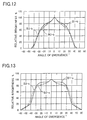
Fig. 13 shows the brightness distribution of the light emerging from the light
shield louver 5 when it offers a range of viewing angles of 120° (±60°) as indicated by (c) in
Fig. 2 and is illuminated with light having a brightness distribution as indicated by (B1), (B2),
and (B3). In this figure, (B 1-c) indicates the case in which the incident light has a brightness
distribution as indicated by (B1), (B2-c) indicates the case in which the incident light has a
brightness distribution as indicated by (B2), and (B3-c) indicates the case in which the
incident light has a brightness distribution as indicated by (B3).
In any of these cases, the relative brightness drops to 0% when the absolute value
of the angle of emergence exceeds 60°. Within a range of angles of emergence of about
±30°, the relative brightness is in a range from 80% to 100%. The effective range of
viewing angles is determined by α ≈ 55°, and the relative brightness when the absolute value
of the angle of emergence is α / 2 is about 80%. Thus, it is possible to realize a liquid
crystal display device 1 that ensures reduced variation in brightness.
However, with an effective range of viewing angles wider than ±40°, this liquid
crystal display device 1 is not suitable for car-mounted use. Designing the light shield
louver 5 to offer a range of viewing angles of 120° or wider results in making the effective
range of viewing angles wider than ±40°, and therefore it is particularly preferable that the
range of viewing angles be 110° or narrower. However, if the range of viewing angles is
narrower than 30°, the peaks (αa and αb in Fig. 5) in the brightness distribution come too
close to each other, and this makes it impossible to obtain minimum brightness at an angle of
incidence of 0°. Accordingly, it is preferable that the range of viewing angles be 30° or
wider.
In the cases indicated by (B2-c) and (B3-c), as compared with the case indicated
by (B-c) in Fig. 8 described earlier, although the peak interval is substantially equal within the
same range of viewing angles (120°), the effective range of viewing angles is wider than
±40°, and this makes the liquid crystal display device 1 unsuitable for car-mounted use.
This is because, whereas in the case indicated by (B-c) the prisms 8a have their vertices
formed into points having a radius of 10 µm or smaller and therefore the light incident on the
prisms 8a emerges therefrom in an uniform direction, in the cases indicated by (B2-c) and
(B3-c) the prisms 8a have their vertices formed into curved surfaces and therefore the light
incident thereon emerges therefrom in scattered directions. Accordingly, it is preferable that
the prisms 8a have their vertices formed into points having a radius of 10 µm or smaller.
Fig. 14 shows the brightness distribution of the light incident on the light shield
louver 5 when the prisms 8a have still another shape. In this figure, (B4) and (B5) indicate
cases in which brightness has more than one maximum, with the peak interval of 30° and 50°,
respectively.
Fig. 15 shows the brightness distribution of the light emerging from the light
shield louver 5 when it offers a range of viewing angles of 120° (±60°) and is illuminated
with light having a brightness distribution as indicated by (B4) and (B5). In this figure, (B4-c)
indicates the case in which the incident light has a brightness distribution as indicated by
(B4), and (B5-c) indicates the case in which the incident light has a brightness distribution as
indicated by (B5).
In either of these cases, the relative brightness drops to 0% when the absolute
value of the angle of emergence exceeds 60°. In a range of angles of emergence of about
±20° and ±25°, respectively, the relative brightness is 80% or more. In the case indicated by
(B4-c), the effective range of viewing angles is determined by α ≈ 30°, and the relative
brightness when the absolute value of the angle of emergence is α / 2 is about 130%. In the
case indicated by (B5-c), the effective range of viewing angles is determined by α ≈ 34°, and
the relative brightness when the absolute value of the angle of emergence is α / 2 is 100% or
more. Thus, it is possible to realize a liquid crystal display device 1 that ensures extremely
reduced variation in brightness within the frequently used range and inconspicuous black lines
in a wide range.
Fig. 16 is a front view showing the liquid crystal display device of a second
embodiment of the invention. For convenience' sake, such members as are found also in the
first embodiment shown in Fig.1 described earlier are identified with the same reference
numerals. The light guide plate 3 has prism-shaped concave pits 3c formed in the back
surface thereof. The pits 3c are so formed as to have an obtuse angle at their vertices. The
light from the light sources 2 is incident on the light guide plate 3 substantially parallel to the
exit surface 3a thereof The light is then reflected from the slant surfaces of the pits 3c so as
to emerge from the light guide plate 3 while traveling in slant directions relative to the
direction perpendicular to the exit surface 3a.
Thus, the light emerging from the light guide plate 3 exhibits high brightness
within a predetermined range of angles that are slant relative to the direction normal to the
light guide plate 3. Here, the light emerging from the light guide plate 3 has been reflected
from the slant surfaces of the pits 3c, and therefore this light emerges at the same intervals at
which the pits 3c are arranged. As a result, even in the same direction of emergence, the
emerging light exhibits uneven brightness in phase with the intervals at which the pits 3c are
arranged. To overcome this, a diffuser sheet 10 is provided between the light guide plate 3
and the light shield louver 5.
The diffuser sheet 10 is made of a resin having a haze value of 40%, and serves to
diffuse the light emerging from the light guide plate 3 so that uniform light is incident on the
light shield louver 5. In this way, it is possible to direct light having a brightness distribution
as shown in Fig. 5 described earlier to the light shield louver 5. Here, the haze value H is
calculated as follows. Suppose that light is incident on the diffuser sheet 10, and that the
portion of the light that is transmitted through the diffuser sheet 10 in the same direction as it
is incident thereon has brightness H1 and the portion of the light that is diffused by the
diffuser sheet 10 has brightness H2. Then, the haze value H is given by H = H2 / (H1 + H2).
In this embodiment also, as in the first embodiment, by properly selecting the
shape of the pits 3c, it is possible to give the light incident on the light shield louver 5 a
brightness distribution such that brightness is at a minimum around an angle of incidence of
0°. In this way, it is possible to limit the light emerging from the light shield louver 5 within
a predetermined effective range of viewing angles. This makes it possible to realize a liquid
crystal display device 1 that ensures reduced variation in the brightness of the light emerging
therefrom and that thus offers satisfactory viewability.
Fig. 17 is a front view showing the liquid crystal display device of a third
embodiment of the invention. For convenience' sake, such members as are found also in the
first and second embodiments shown in Figs. 1 and 16 described earlier are identified with the
same reference numerals. This embodiment differs from the first embodiment only in that a
Fresnel sheet 22 is disposed between the light shield louver 23 and the prism sheet 8, and that
the light shield louver 23 has its light-absorbing layers 23b arranged with an inclination.
Fig. 18 is a sectional view showing the details of the light shield louver 23. The
light shield louver 23 has its light-absorbing layers 23b so formed as to be inclined by an
angle of β relative to the direction normal to the light shield louver 23. Thus, the light shield
louver 23 exhibits highest transmittance to the light L1 that travels parallel to the light-absorbing
layers 23b.
Fig. 19 is a sectional view showing the details of the Fresnel sheet 22. On the
surface of the Fresnel sheet 22 is formed a Fresnel portion 22a having a periodical, sawtooth-shaped
pattern. The Fresnel portion 22a is made of a polyester-based hardening resin, and is
laid on a base member formed out of a 100 µm thick PET film. In the Fresnel portion 22a,
the boundary between two adjacent teeth is formed as a surface perpendicular to the Fresnel
sheet 22.
Fig. 20 shows the brightness distribution of the light incident on the light shield
louver 23, i.e. the light emerging from the Fresnel sheet 22. In this figure, the angle of
incidence (°) with respect to the light shield louver 23 is taken along the horizontal axis, and
the relative brightness (%) is taken along the vertical axis. The prisms 8a of the prism sheet
8 have a vertical angle of 90°, and the light emerging from the prism sheet 8 exhibits, as
indicated by a broken line, a brightness distribution symmetrical about the direction normal
thereto, i.e. the same brightness distribution as indicated by (B) in Fig. 5. The slant surfaces
of the Fresnel sheet 22 are inclined by an angle of y (see Fig. 19) relative to the direction in
which it has the periodic, sawtooth-shaped pattern.
As indicated by (B') in Fig. 20, the light incident on the Fresnel sheet 22 is
refracted so that the light emerging therefrom has a brightness distribution that is non-symmetrical
about the direction normal thereto but that is substantially symmetrical about a
direction about 15° shifted from the normal direction. That is, the Fresnel sheet 22 shifts the
average of the angle of incidence of the light incident on the light shield louver 23 (hereinafter,
this angle will be referred to as the "average angle of incidence") from 0° to -15°.
For this reason, the inclination angle β (see Fig. 18) of the light-absorbing layers
23b of the light shield louver 23 is made equal to 15°. Thus, as shown in Fig. 21, the light
shield louver 23 exhibits the highest transmittance at an angle of incidence of -15°. The
light shield louver 23 here offers a range of viewing angles of 120°. In Fig. 21, the
transmittance (%) is taken along the vertical axis, and the angle of incidence (°) is taken along
the horizontal axis.
As a result, the light emerging from the light shield louver 23 exhibits a brightness
distribution as shown in Fig. 22. In Fig. 22, the relative brightness (%) is taken along the
vertical axis, and the angle of emergence (°) is taken along the horizontal axis. Outside a
range of angles of emergence of -15° ±40°, the relative brightness relative to the highest
brightness is 5% or less; within a range of angles of emergence of -15° ±30°, the relative
brightness is about 80% or more.
In this way, it is possible to achieve the same effect as in the first and second
embodiments. When the liquid crystal display device 1 of this embodiment is mounted on a
car or used in similar applications, there is no need to install it in such a way that the viewer's
eyes lie in the direction normal thereto. Even when the liquid crystal display device 1 is
installed at different angles, as long as it is provided with a light shield louver 23 and a
Fresnel sheet 22 with different inclination angles β and γ (see Figs. 18 and 19), it is possible
to secure high brightness in a predetermined range of angles around the direction in which the
viewer's eyes lie. This helps alleviate restrictions on how the liquid crystal display device 1
should be installed in a car or the like and thereby increase flexibility in installation layout.
In the first to third embodiments, the light sources 2 are composed of a plurality of
fluorescent lamps. By varying the brightness of the fluorescent lamps, it is possible to
reduce the brightness of the light that emerges from the liquid crystal display device 1 outside
the desired range of directions of emergence. How this is achieved will be described below
taking up the third embodiment as an example. As shown in Fig. 17 described earlier, as the
light sources 2, two fluorescent lamps 2a and 2b are arranged in the direction normal to the
liquid crystal panel 6 along each of two opposite sides of the light guide plate 3.
The fluorescent lamps 2a and 2b are controlled by an inverter (not shown). The
inverter is of a single-DC-input, two-transformer type, and is so configured as to permit
adjustment of the duty factor through the operation of a variable resistor. When the input
signal from the variable resistor is within a predetermined range, all the fluorescent lamps 2a
and 2b are lit to emit their maximum amount of light.
When the input signal from the variable resistor is higher than the upper limit of
the predetermined range, the fluorescent lamps 2b farther from the liquid crystal panel 6 are
lit to emit their maximum amount of light, and the fluorescent lamps 2a nearer thereto are lit
to emit a smaller amount of light according to how high the input signal is. When the input
signal from the variable resistor is lower than the lower limit of the predetermined range, the
fluorescent lamps 2a nearer to the liquid crystal panel 6 are lit to emit their maximum amount
of light, and the fluorescent lamps 2b farther therefrom are lit to emit a smaller amount of
light according to how low the input signal is.
Fig. 23 shows the brightness distribution of the light incident on the light shield
louver 23 when the amount of light emitted from the light sources 2 is adjusted. In this
figure, the angle of incidence (°) is taken along the horizontal axis, and the relative brightness
(%) is taken along the vertical axis. In the figure, D1 indicates a case in which the
fluorescent lamps 2a nearer to the light shield louver 23 are lit to emit 50% of the amount of
light they emit in the case indicated by B' in Fig. 20 described earlier; D2 indicates a case in
which the fluorescent lamps 2a are switched off In either case, the fluorescent lamps 2b
farther from the light shield louver 23 are lit to emit their maximum amount of light.
Since the light shield louver 23 exhibits transmittance as shown in Fig. 21
described earlier, the light emerging from the light shield louver 23 exhibits a brightness
distribution as shown in Fig. 24. In this figure, D1' and D2' indicate the cases in which the
incident light has a brightness distribution as indicated by D1 and D2, respectively. In the
figure, the angle of emergence (°) is taken along the horizontal axis, and the relative
brightness (%) is taken along the vertical axis.
In either of these cases, in a range of angles of emergence from 0° to +20°,
brightness as high as in the case shown in Fig. 22 in which all the fluorescent lamps 2a and 2b
are lit to emit their maximum amount of light is obtained. In this way, it is possible to
reduce the amount of light that emerges outside a range of angles of emergence from about 0°
to about +20°.
For example, as shown in Fig. 25, when the liquid crystal display device I is
mounted on a car 30, as long as the viewer remains the same, he or she typically observes the
light emerging therefrom within a narrow range of angles that is determined by his or her
sitting height. When the liquid crystal display device I is installed at a predetermined angle,
a viewer M1 with a high sitting height typically observes the light emerging therefrom within
a range of angles of emergence from about 0° to about +20°; a viewer M2 with an average
sitting height typically observes the light emerging therefrom within a range of angles of
emergence from about 0° to about -20°; a viewer M3 with a low sitting height typically
observes the light emerging therefrom within a range of angles of emergence from about -20°
to about -40°.
Thus, by adjusting the amount of light emitted from the fluorescent lamps 2a and
2b according to their sitting height, the viewers M1, M2, and M3 can reduce the amount of
light that is typically not used for their observation and thereby save the electric power
consumed by the liquid crystal display device 1. When the liquid crystal display device 1 is
viewed by a plurality of viewers, the fluorescent lamps 2a an 2b are made to emit their
maximum amount of light, so that the emerging light exhibits a brightness distribution as
shown in Fig. 22 described earlier. This permits the viewers to observe a sharp image in a
wide range of angles, and also prevents the image from being projected onto the windshield.
In the first to third embodiments, the liquid crystal panel 6 may be of a so-called
semitransparent-reflective type. A liquid crystal panel of a semitransparent-reflective type
displays an image by reflecting ambient light when ambient light is available and by
transmitting the light emitted from the backlight 7 when no ambient light is available.
The light shield louver 5 or 23 may be disposed either in front of or behind the
liquid crystal panel 6. However, when the liquid crystal panel 6 is of a semitransparent-reflective
type, disposing the light shield louver 5 or 23 on the exit surface of the liquid
crystal panel 6 lowers the efficiency with which the liquid crystal panel 6 takes in ambient
light. Therefore, in such a case, it is preferable to dispose the light shield louver 5 or 23
between the liquid crystal panel 6 and the light guide plate 3.