EP1184545A2 - Method and apparatus for injecting hydrogen into a catalytic converter - Google Patents
Method and apparatus for injecting hydrogen into a catalytic converter Download PDFInfo
- Publication number
- EP1184545A2 EP1184545A2 EP01125813A EP01125813A EP1184545A2 EP 1184545 A2 EP1184545 A2 EP 1184545A2 EP 01125813 A EP01125813 A EP 01125813A EP 01125813 A EP01125813 A EP 01125813A EP 1184545 A2 EP1184545 A2 EP 1184545A2
- Authority
- EP
- European Patent Office
- Prior art keywords
- hydrogen
- catalyst
- catalytic converter
- electrolyzer
- engine
- Prior art date
- Legal status (The legal status is an assumption and is not a legal conclusion. Google has not performed a legal analysis and makes no representation as to the accuracy of the status listed.)
- Granted
Links
Images


Classifications
-
- B—PERFORMING OPERATIONS; TRANSPORTING
- B01—PHYSICAL OR CHEMICAL PROCESSES OR APPARATUS IN GENERAL
- B01D—SEPARATION
- B01D53/00—Separation of gases or vapours; Recovering vapours of volatile solvents from gases; Chemical or biological purification of waste gases, e.g. engine exhaust gases, smoke, fumes, flue gases, aerosols
- B01D53/34—Chemical or biological purification of waste gases
- B01D53/92—Chemical or biological purification of waste gases of engine exhaust gases
- B01D53/94—Chemical or biological purification of waste gases of engine exhaust gases by catalytic processes
- B01D53/9445—Simultaneously removing carbon monoxide, hydrocarbons or nitrogen oxides making use of three-way catalysts [TWC] or four-way-catalysts [FWC]
- B01D53/9454—Simultaneously removing carbon monoxide, hydrocarbons or nitrogen oxides making use of three-way catalysts [TWC] or four-way-catalysts [FWC] characterised by a specific device
-
- B—PERFORMING OPERATIONS; TRANSPORTING
- B60—VEHICLES IN GENERAL
- B60H—ARRANGEMENTS OF HEATING, COOLING, VENTILATING OR OTHER AIR-TREATING DEVICES SPECIALLY ADAPTED FOR PASSENGER OR GOODS SPACES OF VEHICLES
- B60H1/00—Heating, cooling or ventilating [HVAC] devices
- B60H1/00271—HVAC devices specially adapted for particular vehicle parts or components and being connected to the vehicle HVAC unit
-
- B—PERFORMING OPERATIONS; TRANSPORTING
- B60—VEHICLES IN GENERAL
- B60H—ARRANGEMENTS OF HEATING, COOLING, VENTILATING OR OTHER AIR-TREATING DEVICES SPECIALLY ADAPTED FOR PASSENGER OR GOODS SPACES OF VEHICLES
- B60H1/00—Heating, cooling or ventilating [HVAC] devices
- B60H1/02—Heating, cooling or ventilating [HVAC] devices the heat being derived from the propulsion plant
- B60H1/14—Heating, cooling or ventilating [HVAC] devices the heat being derived from the propulsion plant otherwise than from cooling liquid of the plant, e.g. heat from the grease oil, the brakes, the transmission unit
- B60H1/18—Heating, cooling or ventilating [HVAC] devices the heat being derived from the propulsion plant otherwise than from cooling liquid of the plant, e.g. heat from the grease oil, the brakes, the transmission unit the air being heated from the plant exhaust gases
-
- B—PERFORMING OPERATIONS; TRANSPORTING
- B60—VEHICLES IN GENERAL
- B60H—ARRANGEMENTS OF HEATING, COOLING, VENTILATING OR OTHER AIR-TREATING DEVICES SPECIALLY ADAPTED FOR PASSENGER OR GOODS SPACES OF VEHICLES
- B60H1/00—Heating, cooling or ventilating [HVAC] devices
- B60H1/22—Heating, cooling or ventilating [HVAC] devices the heat being derived otherwise than from the propulsion plant
- B60H1/2203—Heating, cooling or ventilating [HVAC] devices the heat being derived otherwise than from the propulsion plant the heat being derived from burners
-
- C—CHEMISTRY; METALLURGY
- C25—ELECTROLYTIC OR ELECTROPHORETIC PROCESSES; APPARATUS THEREFOR
- C25B—ELECTROLYTIC OR ELECTROPHORETIC PROCESSES FOR THE PRODUCTION OF COMPOUNDS OR NON-METALS; APPARATUS THEREFOR
- C25B1/00—Electrolytic production of inorganic compounds or non-metals
- C25B1/01—Products
- C25B1/02—Hydrogen or oxygen
- C25B1/04—Hydrogen or oxygen by electrolysis of water
-
- C—CHEMISTRY; METALLURGY
- C25—ELECTROLYTIC OR ELECTROPHORETIC PROCESSES; APPARATUS THEREFOR
- C25B—ELECTROLYTIC OR ELECTROPHORETIC PROCESSES FOR THE PRODUCTION OF COMPOUNDS OR NON-METALS; APPARATUS THEREFOR
- C25B9/00—Cells or assemblies of cells; Constructional parts of cells; Assemblies of constructional parts, e.g. electrode-diaphragm assemblies; Process-related cell features
- C25B9/70—Assemblies comprising two or more cells
- C25B9/73—Assemblies comprising two or more cells of the filter-press type
-
- F—MECHANICAL ENGINEERING; LIGHTING; HEATING; WEAPONS; BLASTING
- F01—MACHINES OR ENGINES IN GENERAL; ENGINE PLANTS IN GENERAL; STEAM ENGINES
- F01N—GAS-FLOW SILENCERS OR EXHAUST APPARATUS FOR MACHINES OR ENGINES IN GENERAL; GAS-FLOW SILENCERS OR EXHAUST APPARATUS FOR INTERNAL COMBUSTION ENGINES
- F01N3/00—Exhaust or silencing apparatus having means for purifying, rendering innocuous, or otherwise treating exhaust
- F01N3/08—Exhaust or silencing apparatus having means for purifying, rendering innocuous, or otherwise treating exhaust for rendering innocuous
- F01N3/10—Exhaust or silencing apparatus having means for purifying, rendering innocuous, or otherwise treating exhaust for rendering innocuous by thermal or catalytic conversion of noxious components of exhaust
- F01N3/18—Exhaust or silencing apparatus having means for purifying, rendering innocuous, or otherwise treating exhaust for rendering innocuous by thermal or catalytic conversion of noxious components of exhaust characterised by methods of operation; Control
- F01N3/20—Exhaust or silencing apparatus having means for purifying, rendering innocuous, or otherwise treating exhaust for rendering innocuous by thermal or catalytic conversion of noxious components of exhaust characterised by methods of operation; Control specially adapted for catalytic conversion ; Methods of operation or control of catalytic converters
- F01N3/2006—Periodically heating or cooling catalytic reactors, e.g. at cold starting or overheating
-
- F—MECHANICAL ENGINEERING; LIGHTING; HEATING; WEAPONS; BLASTING
- F01—MACHINES OR ENGINES IN GENERAL; ENGINE PLANTS IN GENERAL; STEAM ENGINES
- F01N—GAS-FLOW SILENCERS OR EXHAUST APPARATUS FOR MACHINES OR ENGINES IN GENERAL; GAS-FLOW SILENCERS OR EXHAUST APPARATUS FOR INTERNAL COMBUSTION ENGINES
- F01N3/00—Exhaust or silencing apparatus having means for purifying, rendering innocuous, or otherwise treating exhaust
- F01N3/08—Exhaust or silencing apparatus having means for purifying, rendering innocuous, or otherwise treating exhaust for rendering innocuous
- F01N3/10—Exhaust or silencing apparatus having means for purifying, rendering innocuous, or otherwise treating exhaust for rendering innocuous by thermal or catalytic conversion of noxious components of exhaust
- F01N3/18—Exhaust or silencing apparatus having means for purifying, rendering innocuous, or otherwise treating exhaust for rendering innocuous by thermal or catalytic conversion of noxious components of exhaust characterised by methods of operation; Control
- F01N3/20—Exhaust or silencing apparatus having means for purifying, rendering innocuous, or otherwise treating exhaust for rendering innocuous by thermal or catalytic conversion of noxious components of exhaust characterised by methods of operation; Control specially adapted for catalytic conversion ; Methods of operation or control of catalytic converters
- F01N3/206—Adding periodically or continuously substances to exhaust gases for promoting purification, e.g. catalytic material in liquid form, NOx reducing agents
-
- F—MECHANICAL ENGINEERING; LIGHTING; HEATING; WEAPONS; BLASTING
- F01—MACHINES OR ENGINES IN GENERAL; ENGINE PLANTS IN GENERAL; STEAM ENGINES
- F01N—GAS-FLOW SILENCERS OR EXHAUST APPARATUS FOR MACHINES OR ENGINES IN GENERAL; GAS-FLOW SILENCERS OR EXHAUST APPARATUS FOR INTERNAL COMBUSTION ENGINES
- F01N3/00—Exhaust or silencing apparatus having means for purifying, rendering innocuous, or otherwise treating exhaust
- F01N3/08—Exhaust or silencing apparatus having means for purifying, rendering innocuous, or otherwise treating exhaust for rendering innocuous
- F01N3/10—Exhaust or silencing apparatus having means for purifying, rendering innocuous, or otherwise treating exhaust for rendering innocuous by thermal or catalytic conversion of noxious components of exhaust
- F01N3/24—Exhaust or silencing apparatus having means for purifying, rendering innocuous, or otherwise treating exhaust for rendering innocuous by thermal or catalytic conversion of noxious components of exhaust characterised by constructional aspects of converting apparatus
- F01N3/28—Construction of catalytic reactors
- F01N3/2882—Catalytic reactors combined or associated with other devices, e.g. exhaust silencers or other exhaust purification devices
- F01N3/2889—Catalytic reactors combined or associated with other devices, e.g. exhaust silencers or other exhaust purification devices with heat exchangers in a single housing
-
- F—MECHANICAL ENGINEERING; LIGHTING; HEATING; WEAPONS; BLASTING
- F01—MACHINES OR ENGINES IN GENERAL; ENGINE PLANTS IN GENERAL; STEAM ENGINES
- F01N—GAS-FLOW SILENCERS OR EXHAUST APPARATUS FOR MACHINES OR ENGINES IN GENERAL; GAS-FLOW SILENCERS OR EXHAUST APPARATUS FOR INTERNAL COMBUSTION ENGINES
- F01N5/00—Exhaust or silencing apparatus combined or associated with devices profiting from exhaust energy
- F01N5/02—Exhaust or silencing apparatus combined or associated with devices profiting from exhaust energy the devices using heat
-
- F—MECHANICAL ENGINEERING; LIGHTING; HEATING; WEAPONS; BLASTING
- F02—COMBUSTION ENGINES; HOT-GAS OR COMBUSTION-PRODUCT ENGINE PLANTS
- F02B—INTERNAL-COMBUSTION PISTON ENGINES; COMBUSTION ENGINES IN GENERAL
- F02B43/00—Engines characterised by operating on gaseous fuels; Plants including such engines
- F02B43/10—Engines or plants characterised by use of other specific gases, e.g. acetylene, oxyhydrogen
-
- F—MECHANICAL ENGINEERING; LIGHTING; HEATING; WEAPONS; BLASTING
- F01—MACHINES OR ENGINES IN GENERAL; ENGINE PLANTS IN GENERAL; STEAM ENGINES
- F01N—GAS-FLOW SILENCERS OR EXHAUST APPARATUS FOR MACHINES OR ENGINES IN GENERAL; GAS-FLOW SILENCERS OR EXHAUST APPARATUS FOR INTERNAL COMBUSTION ENGINES
- F01N2240/00—Combination or association of two or more different exhaust treating devices, or of at least one such device with an auxiliary device, not covered by indexing codes F01N2230/00 or F01N2250/00, one of the devices being
- F01N2240/02—Combination or association of two or more different exhaust treating devices, or of at least one such device with an auxiliary device, not covered by indexing codes F01N2230/00 or F01N2250/00, one of the devices being a heat exchanger
-
- F—MECHANICAL ENGINEERING; LIGHTING; HEATING; WEAPONS; BLASTING
- F01—MACHINES OR ENGINES IN GENERAL; ENGINE PLANTS IN GENERAL; STEAM ENGINES
- F01N—GAS-FLOW SILENCERS OR EXHAUST APPARATUS FOR MACHINES OR ENGINES IN GENERAL; GAS-FLOW SILENCERS OR EXHAUST APPARATUS FOR INTERNAL COMBUSTION ENGINES
- F01N2610/00—Adding substances to exhaust gases
- F01N2610/04—Adding substances to exhaust gases the substance being hydrogen
-
- F—MECHANICAL ENGINEERING; LIGHTING; HEATING; WEAPONS; BLASTING
- F01—MACHINES OR ENGINES IN GENERAL; ENGINE PLANTS IN GENERAL; STEAM ENGINES
- F01N—GAS-FLOW SILENCERS OR EXHAUST APPARATUS FOR MACHINES OR ENGINES IN GENERAL; GAS-FLOW SILENCERS OR EXHAUST APPARATUS FOR INTERNAL COMBUSTION ENGINES
- F01N2610/00—Adding substances to exhaust gases
- F01N2610/08—Adding substances to exhaust gases with prior mixing of the substances with a gas, e.g. air
-
- F—MECHANICAL ENGINEERING; LIGHTING; HEATING; WEAPONS; BLASTING
- F01—MACHINES OR ENGINES IN GENERAL; ENGINE PLANTS IN GENERAL; STEAM ENGINES
- F01N—GAS-FLOW SILENCERS OR EXHAUST APPARATUS FOR MACHINES OR ENGINES IN GENERAL; GAS-FLOW SILENCERS OR EXHAUST APPARATUS FOR INTERNAL COMBUSTION ENGINES
- F01N3/00—Exhaust or silencing apparatus having means for purifying, rendering innocuous, or otherwise treating exhaust
- F01N3/08—Exhaust or silencing apparatus having means for purifying, rendering innocuous, or otherwise treating exhaust for rendering innocuous
- F01N3/10—Exhaust or silencing apparatus having means for purifying, rendering innocuous, or otherwise treating exhaust for rendering innocuous by thermal or catalytic conversion of noxious components of exhaust
- F01N3/24—Exhaust or silencing apparatus having means for purifying, rendering innocuous, or otherwise treating exhaust for rendering innocuous by thermal or catalytic conversion of noxious components of exhaust characterised by constructional aspects of converting apparatus
- F01N3/30—Arrangements for supply of additional air
- F01N3/32—Arrangements for supply of additional air using air pump
-
- F—MECHANICAL ENGINEERING; LIGHTING; HEATING; WEAPONS; BLASTING
- F01—MACHINES OR ENGINES IN GENERAL; ENGINE PLANTS IN GENERAL; STEAM ENGINES
- F01N—GAS-FLOW SILENCERS OR EXHAUST APPARATUS FOR MACHINES OR ENGINES IN GENERAL; GAS-FLOW SILENCERS OR EXHAUST APPARATUS FOR INTERNAL COMBUSTION ENGINES
- F01N3/00—Exhaust or silencing apparatus having means for purifying, rendering innocuous, or otherwise treating exhaust
- F01N3/08—Exhaust or silencing apparatus having means for purifying, rendering innocuous, or otherwise treating exhaust for rendering innocuous
- F01N3/10—Exhaust or silencing apparatus having means for purifying, rendering innocuous, or otherwise treating exhaust for rendering innocuous by thermal or catalytic conversion of noxious components of exhaust
- F01N3/24—Exhaust or silencing apparatus having means for purifying, rendering innocuous, or otherwise treating exhaust for rendering innocuous by thermal or catalytic conversion of noxious components of exhaust characterised by constructional aspects of converting apparatus
- F01N3/30—Arrangements for supply of additional air
- F01N3/34—Arrangements for supply of additional air using air conduits or jet air pumps, e.g. near the engine exhaust port
-
- F—MECHANICAL ENGINEERING; LIGHTING; HEATING; WEAPONS; BLASTING
- F01—MACHINES OR ENGINES IN GENERAL; ENGINE PLANTS IN GENERAL; STEAM ENGINES
- F01P—COOLING OF MACHINES OR ENGINES IN GENERAL; COOLING OF INTERNAL-COMBUSTION ENGINES
- F01P2060/00—Cooling circuits using auxiliaries
-
- F—MECHANICAL ENGINEERING; LIGHTING; HEATING; WEAPONS; BLASTING
- F01—MACHINES OR ENGINES IN GENERAL; ENGINE PLANTS IN GENERAL; STEAM ENGINES
- F01P—COOLING OF MACHINES OR ENGINES IN GENERAL; COOLING OF INTERNAL-COMBUSTION ENGINES
- F01P2060/00—Cooling circuits using auxiliaries
- F01P2060/18—Heater
-
- F—MECHANICAL ENGINEERING; LIGHTING; HEATING; WEAPONS; BLASTING
- F02—COMBUSTION ENGINES; HOT-GAS OR COMBUSTION-PRODUCT ENGINE PLANTS
- F02B—INTERNAL-COMBUSTION PISTON ENGINES; COMBUSTION ENGINES IN GENERAL
- F02B43/00—Engines characterised by operating on gaseous fuels; Plants including such engines
- F02B43/10—Engines or plants characterised by use of other specific gases, e.g. acetylene, oxyhydrogen
- F02B2043/106—Hydrogen obtained by electrolysis
-
- Y—GENERAL TAGGING OF NEW TECHNOLOGICAL DEVELOPMENTS; GENERAL TAGGING OF CROSS-SECTIONAL TECHNOLOGIES SPANNING OVER SEVERAL SECTIONS OF THE IPC; TECHNICAL SUBJECTS COVERED BY FORMER USPC CROSS-REFERENCE ART COLLECTIONS [XRACs] AND DIGESTS
- Y02—TECHNOLOGIES OR APPLICATIONS FOR MITIGATION OR ADAPTATION AGAINST CLIMATE CHANGE
- Y02A—TECHNOLOGIES FOR ADAPTATION TO CLIMATE CHANGE
- Y02A50/00—TECHNOLOGIES FOR ADAPTATION TO CLIMATE CHANGE in human health protection, e.g. against extreme weather
- Y02A50/20—Air quality improvement or preservation, e.g. vehicle emission control or emission reduction by using catalytic converters
-
- Y—GENERAL TAGGING OF NEW TECHNOLOGICAL DEVELOPMENTS; GENERAL TAGGING OF CROSS-SECTIONAL TECHNOLOGIES SPANNING OVER SEVERAL SECTIONS OF THE IPC; TECHNICAL SUBJECTS COVERED BY FORMER USPC CROSS-REFERENCE ART COLLECTIONS [XRACs] AND DIGESTS
- Y02—TECHNOLOGIES OR APPLICATIONS FOR MITIGATION OR ADAPTATION AGAINST CLIMATE CHANGE
- Y02E—REDUCTION OF GREENHOUSE GAS [GHG] EMISSIONS, RELATED TO ENERGY GENERATION, TRANSMISSION OR DISTRIBUTION
- Y02E60/00—Enabling technologies; Technologies with a potential or indirect contribution to GHG emissions mitigation
- Y02E60/30—Hydrogen technology
- Y02E60/36—Hydrogen production from non-carbon containing sources, e.g. by water electrolysis
-
- Y—GENERAL TAGGING OF NEW TECHNOLOGICAL DEVELOPMENTS; GENERAL TAGGING OF CROSS-SECTIONAL TECHNOLOGIES SPANNING OVER SEVERAL SECTIONS OF THE IPC; TECHNICAL SUBJECTS COVERED BY FORMER USPC CROSS-REFERENCE ART COLLECTIONS [XRACs] AND DIGESTS
- Y02—TECHNOLOGIES OR APPLICATIONS FOR MITIGATION OR ADAPTATION AGAINST CLIMATE CHANGE
- Y02T—CLIMATE CHANGE MITIGATION TECHNOLOGIES RELATED TO TRANSPORTATION
- Y02T10/00—Road transport of goods or passengers
- Y02T10/10—Internal combustion engine [ICE] based vehicles
- Y02T10/12—Improving ICE efficiencies
-
- Y—GENERAL TAGGING OF NEW TECHNOLOGICAL DEVELOPMENTS; GENERAL TAGGING OF CROSS-SECTIONAL TECHNOLOGIES SPANNING OVER SEVERAL SECTIONS OF THE IPC; TECHNICAL SUBJECTS COVERED BY FORMER USPC CROSS-REFERENCE ART COLLECTIONS [XRACs] AND DIGESTS
- Y02—TECHNOLOGIES OR APPLICATIONS FOR MITIGATION OR ADAPTATION AGAINST CLIMATE CHANGE
- Y02T—CLIMATE CHANGE MITIGATION TECHNOLOGIES RELATED TO TRANSPORTATION
- Y02T10/00—Road transport of goods or passengers
- Y02T10/10—Internal combustion engine [ICE] based vehicles
- Y02T10/30—Use of alternative fuels, e.g. biofuels
-
- Y—GENERAL TAGGING OF NEW TECHNOLOGICAL DEVELOPMENTS; GENERAL TAGGING OF CROSS-SECTIONAL TECHNOLOGIES SPANNING OVER SEVERAL SECTIONS OF THE IPC; TECHNICAL SUBJECTS COVERED BY FORMER USPC CROSS-REFERENCE ART COLLECTIONS [XRACs] AND DIGESTS
- Y10—TECHNICAL SUBJECTS COVERED BY FORMER USPC
- Y10S—TECHNICAL SUBJECTS COVERED BY FORMER USPC CROSS-REFERENCE ART COLLECTIONS [XRACs] AND DIGESTS
- Y10S123/00—Internal-combustion engines
- Y10S123/12—Hydrogen
Definitions
- the present invention relates generally to the field of catalysis for the reduction of emissions from internal combustion engines, More particularly, the present invention relates to a method and apparatus for heating a catalyst by spontaneous combustion of hydrogen introduced into the catalyst. More particularly still, the present invention relates to the conditioning through preheating of a standard three-way or two-way catalytic monolith in a vehicle powered by an internal combustion engine, such as an automobile.
- a catalytic converter is located in the exhaust stream of the engine.
- the converter typically includes a canister holding a suitable catalyst, such as a three-way catalytic converter (TWC) catalyst monolith, that will oxygenate unburned, unacceptable components in the exhaust stream including hydrocarbons (HC), their partially oxidized derivatives such as aldehydes and carbon monoxide (CO), and at the same time reducing nitrogen oxides (NO x ), after almost stoichiometric fuel burn with oxygen in the cylinders of the engine.
- TWC three-way catalytic converter
- the exhaust gas is passed through the catalyst monolith, thereby completing the oxygenation of unburned HC and CO, and the reduction of NO x in the exhaust to convert these unacceptable emissions into acceptable emissions.
- TWC catalysts are currently formulated and designed to be effective over a specific operating range of both lean and rich fuel/air conditions and a specific operating temperature range. These particulate catalyst compositions enable optimization of the conversion of HC, CO, and NO x .
- This purification of the exhaust stream by the catalytic converter is dependent on the temperature of the exhaust gas and the catalytic converter works optimally at an elevated temperature, generally at or above about 300°C.
- the time span between when the exhaust emissions begin (i.e., "cold start"), until the time when the substrate heats up sufficiently for the catalyst to work efficiently, is generally referred to as the light-off time.
- Light-off temperature is generally defined as the temperature at which fifty percent (50%) of the emissions from the engine are being converted as they pass through the catalyst.
- the conventional method of heating the catalytic converter is to heat the catalyst by contact with high temperature exhaust gases from the engine.
- This heating in conjunction with the exothermic nature of the oxidation reaction occurring at the catalyst, will bring the catalyst to light-off temperature.
- the exhaust gas passes through the catalyst relatively unchanged.
- the composition of the engine exhaust changes as the engine heats from the cold start temperature, and the catalyst is designed to work best with the composition of the exhaust stream present at the normal elevated engine operating temperature.
- EHC electrolytic converters
- the primary limitation on electrical preheating is the electrical energy required by the heater.
- the typical car battery is not a practical power source to supply the electrical power because the electrical load on the vehicle battery during the period required may exceed the rated battery output. In any event, the load placed on a typical 12 volt vehicle battery will shorten the lifetime of the battery. Also, there is a measurable delay between the time the operator of the vehicle places the ignition switch in the "on" position and the time the heater brings the catalyst to light-off temperature.
- the exhaust stream is oxygen deficient. Because the catalyst requires oxygen to complete the catalytic reaction, supplemental air must be blown over the catalyst. Even when using a secondary air flow to overcome oxygen deficiency, the secondary air flow must be closely controlled to avoid an excess of oxygen, in which case the catalytic converter is less effective in reducing NO x , However, it should be noted that NO, contributes a very small portion of unacceptable emissions when an engine is cold; most of the emissions that must be dealt with comprise HC, CO and the like.
- An alternative to battery powered electrical heating has been to decrease the strain on the power supply by supplying the power directly from an alternator rather than directly from the vehicle battery.
- An alternator powered, electrically heated catalyst (“APEHC”) still requires a 5 to 10% increase in battery capacity to cope with the EHC star-up scenario. Even with the APEHC system, there still is a concern with respect to battery capacity because electric heating is needed for an extended period of time, i.e., more than 25-30 seconds.
- the maximum alternator power output required in the APEHC system requires a complicated switching mechanism and an altered alternator speed between 2,000 and 4,500 rpm during the heating up time period, and the alternator must be oversized.
- the multi-chamber configurations of catalytic converters generally conform to one or two theories.
- a small portion of catalyst known as a "starter catalyst” is positioned upstream from the primary catalyst.
- This "starter catalyst” is generally closer to the exhaust manifold. This location, in conjunction with a smaller thermal mass associated with its smaller size, causes the catalyst to heat much more quickly than a single catalyst.
- This configuration is generally unacceptable because the starter catalyst in the exhaust stream creates a higher back pressure which reduces the overall engine efficiency and robs the engine of power output.
- Another method of providing multiple chambers in the exhaust flow includes a first catalyst having low temperature characteristics used only during cold start conditions, and, after the catalyst temperature rises to a selected elevated level, the exhaust gas flow is switched to pass through the conventional catalytic converter configuration.
- a variation of this approach is to run all cold start emissions through a separate absorber (such as a zeolite or a metal sieve-type substance) where unacceptable emissions are captured and later released back into the exhaust stream.
- a separate absorber such as a zeolite or a metal sieve-type substance
- the present invention provides a catalytic converter system for the exhaust of an internal combustion engine with an exhaust line, comprising: a catalytic converter in the exhaust line; a source of hydrogen; a conduit connecting the source of hydrogen to the exhaust line upstream of the catalytic converter; a temperature sensor in the catalytic converter; and means for controlling the introduction of hydrogen from the source of hydrogen to the exhaust line, based on a temperature sensed by the temperature sensor.
- a catalytic converter in the exhaust line of an internal combustion engine comprising: a canister; a plurality of catalytic monoliths within the canister; a source of hydrogen; a gap between each of the plurality of monoliths; and means for introducing hydrogen from the source of hydrogen into the canister upstream of the plurality of monoliths and into the gap between each of the plurality of monoliths.
- the means for introducing hydrogen may comprise a manifold within or outside the canister.
- Yet another aspect of the invention provides a catalytic converter system for the exhaust of an internal combustion engine with an exhaust line, comprising: a catalytic converter in the exhaust line; a source of hydrogen; a conduit connecting the source of hydrogen to the exhaust line upstream of the catalytic converter; a source of oxygen; means for controlling the introduction of hydrogen from the source of hydrogen to the exhaust line; means for controlling the introduction of oxygen from the source of oxygen to the exhaust line, independent of the means for controlling the introduction of hydrogen; an isolation valve in the exhaust line upstream of the catalytic converter; and an isolation valve in the exhaust line downstream of the catalytic converter.
- the present invention also provides a heater for the passenger compartment of a vehicle, comprising: a heat exchanger defining a first path for the flow of air to the passenger compartment and a second path, isolated from the first path, for the flow of combustion gases; a catalytic converter in the second path; and means for introducing hydrogen and oxygen into the catalytic converter.
- the present invention provides a method and apparatus for chemically heating by feeding hydrogen to a catalyst.
- the invention also provides a method and apparatus for thermally conditioning a catalyst in order to enhance the conversion of unacceptable emissions emanating from an internal combustion engine into water and other acceptable emissions.
- hydrogen is supplied from an electrolyzer or other hydrogen source and injected into the monolith of a catalytic converter to more rapidly bring the catalyst to a light-off temperature.
- Figure 1 shows a system 10 of the present invention installed on a vehicle exhaust system.
- the vehicle includes a catalytic converter 11 located in an exhaust line 42 from a vehicle's exhaust manifold, as shown.
- the exhaust line 42 is provided with air from an air pump 44 and hydrogen from a hydrogen inlet line 46.
- the air pump could be any suitable air source, such as a receiver, for injecting air into the exhaust line at suitable pressure and volumetric flow rate to achieve the ideal air/hydrogen ratio mixture.
- the hydrogen supply system of the invention generally includes a water reservoir 48, an electrolyzer 50, and a hydrogen storage cylinder 52.
- the electrolyzer 50 may preferably compromise a plurality of stacked identical cells 51.
- the reservoir 48 serves both as a water reservoir and as a separator for oxygen and water.
- the reservoir 48 may be a vehicle's windshield washer fluid storage container, but is preferably a dedicated separator allowing collection and storage of oxygen via port 54. Water flows by gravity drain or is pumped from the reservoir 48 to the electrolyzer 50 via a drain line 56. As the electolyzer produces hydrogen and oxygen, the oxygen and entrained water flows naturally back to the reservoir 48 via a return line 58.
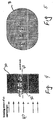
- the next major component of the hydrogen source is the electrolyzer 50, shown in greater detail in Figure 2.
- the materials of construction referred to as "preferred" are the material actually used in a test device to prove that the invention would work for its intended purpose.
- less expensive materials will be used throughout, such as carbon steel for titanium where possible, and plastic such as polypropylene where heat and stress will permit the use of such material.
- the electrolyzer 50 may be referred to herein as a proton exchange membrane (PEM) electrolyzer 50.
- the proton exchange membrane itself may prove corrosive in this environment in contact with certain substances, thus requiring the careful selection of the material of construction of the electrolyzer.
- the PEM should only contact carbon or graphite.
- graphite will be the material of choice in certain structural elements, and not some obvious candidates such as copper, aluminum, or iron, which can corrode thus forming ions that can poison the oxygen and/or hydrogen electrode catalysts,
- the PEM electrolyzer 50 is shown as a cell stack including a pair of endplates 60 and 62.
- the endplates 60 and 62 are preferably titanium and measure 4.2" x 4.2" x 3/4".
- Adjacent the top endplate 60 is an anodic cell frame 64.
- the cell frame 64 is preferably a carbon fiber-filled Teflon sheet, sold under the trademark Zymaxx by Du Pont.
- the cell frame 64 retains a 1:1 molar ratio of iridium and ruthenium dioxides (IrO 2 /RuO 2 ) as the anodic electrocatalyst.
- the cell frame 64 also includes a plurality of flow ports 66 to permit the supply of reactant (water) and/or removal of electrolysis product (oxygen gas).
- an expanded titanium metal current collector (flow field) 68 preferably 25 Ti 40-3/32 from Exmet Corp.
- An anode substrate 70 is preferably a porous titanium plate measuring 2.49" x 2.49" x 0.05".
- a proton exchange membrane 72 cut from a sheet of Nafion 117 from Du Pont which serves as a solid electrolyte material and which is 175 ⁇ m thick.
- Figure 2 depicts a gasket 74, one of perhaps several installed where required.
- Gaskets 74 are stamped from 0.033" thick fluorosilicone sheet (Viton) and from 0.005" thick unsintered PTFE sheet.
- the electrolyzer 50 further includes a cathode substrate 76 like the anode substrate 70 and an expanded titanium flow field.
- the PEM electrolyzer 50 includes a cathodic cell frame 80 formed of polychlorotrifluorethylene (PCTFE) sheet, sold under the trademark KEL-F by Afton Plastics,
- the cathodic cell frame 80 retains a fuel cell gas diffusion electrode containing high surface area colloidal platinum, supported on platinum black, having platinum loading of 4.0 mg/cm 2 as the cathodic electrocatalyst layer.
- the various components of the PEM electrolyzer are stacked together and retained with a plurality of tie rods 82, preferably 16 such tie rods.
- Stainless steel tubing, such as SS316 are then screwed into four threaded ports on one of the titanium endplates.
- the ports are the water inlet port 56, the oxygen outlet port 58, and a pair of hydrogen outlet ports 84.
- the titanium endplates 60 and 62 and the expanded titanium metal current collectors 68 and 78 may be electroplated with a thin film of gold or other noble metals, such as platinum.
- the cathode and the anode of the electrolyzer are of special construction.
- the cathodic electrode structure for hydrogen evolution is fashioned from a commercially available fuel cell gas diffusion layer on a carbon cloth backing, which acts as a support for the active hydrophilic electrocatalyst layer.
- This active layer contains high surface area colloidal platinum (100m 2 /g), supported on carbon black (60 wt % Pt on C), yielding a platinum loading of 4.0 mg/cm 2 .
- the cathodic electrode structure having an area of 40 cm 2 , was hot-pressed onto one side of a segment of precleaned Nafion 117 PEM material. Hot-pressing was carried out between the plates of a hot-press elevated to 200°C for 60 seconds, and using a force of 15,000 pounds.
- anodic electrocatalyst layer For the anodic electrocatalyst layer, a 1:I molar ratio of iridium and ruthenium chlorides are dissolved in ca. 8 ml of concentrated HCl and heated to almost dryness. The resulting chlorides are then dissolved in isopropanol to make an ink-line coating.
- This substrate is then coated with the ink-like mixture and the solvent evaporated under low heat of about 90°C.
- This coating and drying procedure is repeated seven times, then the electrode is heated in a fumace at 400°C for 10 minutes in ambient air. The coating, drying, and fumace treatment is repeated twice more, but with a final baking time of two hours instead of 10 minutes.
- the system further includes a hydrogen storage cylinder and various supporting components in addition to the reservoir 48 and the electrolyzer 50, described above.
- the components include a liquid water trap 86 to eliminate most of the entrained water from the hydrogen exiting the electrolyzer, a solenoid valve 88 to blow out the trap, a check valve 90, and a pressure relief valve 92 to protect the system against over pressurization.
- Figure 3 depicts additional details and a preferred arrangement of the hydrogen gas handling and capture system.
- the electrolyzer 50 includes a proton exchange membrane in its construction so that generated oxygen is vented to the water source reservoir and the hydrogen generated can be accumulated at pressure.
- the system of Figure 3 permits purging with an inert gas, such as nitrogen.
- an inert gas such as nitrogen.
- all air is first removed from the system by attaching a nitrogen gas feedline at a purge gas inlet 94 downstream of a check valve 90.
- the hydrogen storage cylinder or vessel 52 such as a metal hydride vessel, is detached at a quick disconnect 96. This operation effectively seals both the vessel 52 and a gas line 98, to keep the purge gas out of the vessel 52.
- the remainder of the system is then purged from the purge gas inlet 94 through a back pressure regulator 100.
- the needle valve 102 between the storage vessel 52 and the back pressure regulator 100 is shut.
- Hydrogen gas generated by the electrolyzer is processed through a four-stage process to remove entrained water (liquid or vapor) and any oxygen contaminant from the hydrogen stream before storage.
- the first step involves removal of a small amount of entrained liquid water coming from the electrolyzer in the hydrogen gas. This entrained liquid water is removed without a pressure loss by means of the entrained liquid water trap 86.
- the second step involves cooling the hydrogen gas stream from the electrolyzer temperature to ambient in a condensing coil 104.
- the electrolyzer typically operates at about 20°C above ambient, with the exact temperature depending on specific electrolyzer operating conditions.
- This second step condenses a substantial portion of the water vapor in the hydrogen gas stream.
- This condensed water could absorb a significant amount of alcohol, which may be present during operation using windshield washer fluid as the electrolyzer reactant feed.
- the condensate is collected in a condensate collector 106 and removed through a drain valve 108.
- the hydrogen gas stream is still saturated with water vapor, but now at a lower temperature.
- This saturated gas stream is next passed into a zeolite-filled gas drier 110.
- This drier absorbs water vapor and any alcohol vapor present when using a windshield washer fluid feed. Any oxygen contaminant present in the hydrogen gas stream is then eliminated in a catalytic recombiner or oxygen eliminator 112 to reduce it to water.
- Final clean-up of the hydrogen gas stream is accomplished in a second zeolite absorber bed in a polishing drier 114.
- the polishing drier removes traces of water produced by the catalytic recombiner 112.
- the hydrogen gas handling system of Figure 3 is designed for relatively short term operation; longer term operations, for example 100,000 miles, would utilize other methods of water removal known in the art.
- a satisfactory metal hydride hydrogen storage unit is available from Hydrogen Consultants of Littleton, Colorado, Such an available unit can store 30 liters of hydrogen which can be delivered at 30-45 psig, with recharging using hydrogen gas at 100-200 psig.
- the hydrogen storage vessel is a pressure vessel made of a composite structure, aluminum or ferrous-based alloys.
- a suitable hydrogen storage vessel of this type is available from Harless Specialties.
- FIG. 4 a simplified cross-sectional view of a catalytic converter monolith shows air and hydrogen flow in the axial direction through the monolith 30.
- the temperature of the monolith is measured with a thermocouple at points 31(a)-(e) along the central axis, with point 31(a) being on the front face where the gases first contact the catalyst and the other points 31(b)-(e) located at positions successively further into the monolith.
- the results of these temperature measurements at 40 liters per minute (1pm) total gas flow rate containing 3%, 5%, 8.5% and 17% hydrogen is shown in Figures 6(a)-(d).
- Figures 6(a)-(d) are graphs of the catalyst temperature measured at axial positions within the monolith as indicated in Figure 4.
- a simplified cross-sectional view of a catalytic converter monolith shows air and hydrogen flow in the radial direction through the monolith 30.
- the temperature of the monolith is measured with a thermocouple at points 33(a)-(c) along the monolith radius, with point 33(c) being in the center of the monolith and the other points 31(b) and (a) located at greater distances from the center.
- the results of these temperature measurements at 40 liters per minute (1pm) total gas flow rate containing 3%, 5%, 8.5% and 17% hydrogen is shown in Figures 7(a)-(d).
- Figures 7(a)-(d) are graphs of the catalyst temperature measured at radial positions within the monolith as indicated in Figure 5.
- the air flow rate typically falls in the range of 40 to 250 liters per minute (lmp).
- the ideal range is between 80 and 200 lmp, depending on engine size. Effective concentrations of hydrogen for these flow rates are one to twenty-eight volume percent, with a preferred range of five to eighteen percent.
- the ideal range of hydrogen concentration again depending on engine size, has been found to be eight to fifteen percent. For example, at 150 Imp flow rate across the catalytic converter, the ideal range of hydrogen concentration in that flow is 12 to 13 volume percent. Under those conditions, light-off temperature at the face 32 is reached in about one second. At 90 Imp and at 8.5 to 11 volume percent hydrogen, light-off is achieved in about two seconds,
- the power consumption of the catalyst varies depending on the flow rate and the concentration of hydrogen. For example, at a flow rate of 30 to 50 lpm and a concentration of 10-11 1 ⁇ 2 volume percent hydrogen, the power required to heat the monolith to light-off is approximately 1.5 watt hours. Similar results in the electrically heated catalyst (EHC) unit require approximately 10 to 15 watt hours.
- EHC electrically heated catalyst
- the present invention is also suitable for use in low ambient temperature conditions, as low as -7°C or lower.
- the amount of time required to achieve light-off may double.
- one aspect of the invention provides an on-board hydrogen ignition assist system.
- a source of hydrogen such as the electrolyzer described above or any suitable means, fills the hydrogen storage cylinder 52.
- An ignition supply line to a control valve 122 controls the supply of hydrogen into an engine ignition 124.
- the engine ignition 124 includes the fuel, air, and electrical components for an internal combustion engine 126.
- the hydrogen can be supplied at any convenient location so that it is injected into the cylinders of the engine 126.
- hydrogen under pressure can be supplied to the intake manifold where there is already a fuel/air mixture (during the inlet cycle), or the hydrogen can be mixed with air before it goes to the engines fuel injection system, or other means.
- the system of Figure 8 turns the internal combustion engine 126 into a hydrogen fuel injected engine for the first few seconds of start-up, before any gasoline is introduced into the engine. This way, the catalytic converter can be brought to light-off temperature before the engine begins producing undesirable emissions. Then, when gasoline is finally injected into the system, the catalytic converter is heated to an efficient operating temperature.
- Expended fuel gases are collected in an output manifold 128 and flow into the exhaust line 42.
- An ignition control 130 provides control signals to the control valve 122 for the introduction of hydrogen and to the engine ignition 124 to coordinate hydrogen introduction during cold start operations,
- the on-board hydrogen ignition assist system functions with or without the catalyst conditioning system but preferably included with such a system since they may both use the hydrogen generation and on-board storage.
- FIG. 9 a schematic diagram of a system having oxygen recovery and storage equipment is shown providing for injection of oxygen into the catalytic converter.
- the oxygen separated from water in the water reservoir 48 passes through the port 54 and is collected in a storage vessel or cylinder 55.
- the oxygen may be released from the vessel 55 by opening a valve 57 and input into the air pump 44. In this manner, the oxygen enriches the air and provides more efficient combustion of the hydrogen or exhaust gases within the catalytic converter 11.
- FIG. 10 a schematic diagram of a system is shown having the air pump replaced with a venturi for drawing air into the catalytic converter.
- This aspect or embodiment of the invention climinates the need for an air pump by drawing air into the hydrogen delivery line 46.
- a power source 132 is coupled to the hydrogen solenoid valve 138 upon engaging the ignition switch 134.
- the solenoid valve 138 may remain open or be pulsed until the thermocouple 136 reads a temperature equal to or greater than the light-off temperature.
- the electrolyzer 50 receives power from the source 132 when the hydrogen pressure in or near the hydrogen storage vessel 52, as indicated by pressure sensor 133, falls below a setpoint pressure between about 100 psig and about 400 psig. It should be recognized that the power to the electrolyzer 50 is turned off when the pressure exceeds a high pressure setpoint, such as 400 psig. It should also be recognized that many other conditions may be considered in controlling the electrolyzer.
- a control diagram illustrates a catalytic converter system 140, similar to that of Figure 1, using a microprocessor controller 142 to monitor and control various functions of the system.
- the temperature of the catalytic converter 11 as measured by the thermocouple 136 is communicated to the microprocessor controller 142.
- the controller 142 may then send a signal to the hydrogen release valve 138 to close when the temperature exceeds a light-off temperature.
- power to the electrolyzer 50 may be supplied under various conditions such as when the pressure sensor 133 indicates a low pressure in the storage tank 52.
- the microprocessor may also be programmed to carry out timed control function apart from responding to sensory inputs, and may also serve various safety functions.
- FIGs 12(a) and (b) graphs are provided showing the catalyst temperature at various axial distances and radial distances in the catalyst monolith over a period of 50 seconds using a pulsed release of hydrogen into an air stream.
- the graphs show the temperature rise in the catalytic converter monolith at an air flow rate of 90 lpm and pulsed hydrogen flow controlled by a microprocessor.
- the pulsed hydrogen flow was provided by opening the hydrogen release valve 138 (see Figure 1) for 0.01 seconds and closing the valve for 0.66 seconds, successively 10 times.
- FIG. 13 a graph of the pressure in the hydrogen storage tank after successive pulsed hydrogen releases with valve open time of 0,01 seconds and valve closed time of 0.66 seconds. Over a period of 40 pulses, the 12 liter hydrogen storage vessel is depleted to about 3 liters with a decrease in pressure from about 350 psig to about 100 psig.
- FIG 14 is a schematic diagram of a heat exchanger 150 having a catalyst 152 formed on one surface receiving hydrogen and oxygen and another surface suitable for the passage of air for cabin circulation.
- the heat exchanger may be of any type or style, such as a shell and tube heat exchanger having cabin air flow on the shell side 154 and the hydrogen/oxygen mixture on the tube side 156.
- the catalyst 152 is preferably formed on the internal surface of the tubes 158. It is also preferred that the heat exchanger be incorporated into or compatible with existing air circulation systems in a vehicle.
- a preferred configuration of the cabin heater is shown in Figure 21 wherein the cabin air flow passes through a freon loop, a radiator hot water loop, and the external surface of a heat exchanger having an internal surface coated with a noble metal catalyst.
- FIG. 15 a schematic diagram of a catalytic combination gas heater 160 for a diesel engine 162 is shown.
- the catalytic combination gas heater 160 is filled or lined with a suitable catalyst for combination of hydrogen and oxygen to heat ambient air entering from the intake 164.
- Hydrogen from supply line 166, and preferably oxygen from supply line 168, are delivered to the catalytic heater 160 before entering the combustion chamber 170 of the diesel engine 162.
- the diesel injector 172 provides atomized diesel fuel to the chamber 170. Without the catalytic heater 160, the ambient temperature of the air passing into the chamber 170 through the air intake valve 174 may not be sufficiently warm to prevent condensation of the fuel on the chamber walls.
- the catalytic heater 160 is capable of heating the air sufficiently so that the fuel does not condense and the engine may be more readily started.
- FIG. 16 a schematic diagram of an electrolyzer 180 is shown having dummy cells 182 for healing or cooling the electrolyzer using liquid from a vehicle radiator 184.
- the dummy cells 182 may be comprised of plates providing a passage for the radiator fluid between electrolytic cells 184 in order to absorb or deliver heat to the electrolyzer. Because electrolyzers operate most efficiently at elevated temperatures, the radiator may be used to warm the electrolyzer in cold weather conditions. Alternately, the radiator fluid may be used to cool the electrolyzer after an extended period of use.
- FIGs 17(a) and (b) two catalytic converters 11 are shown having hydrogen injection manifolds 190.
- the converters 11 have multiple monoliths 194 separated by a short distance for hydrogen introduction and diffusion.
- the manifold is external to the converter 11 with a plurality of injection tubes 192 delivering hydrogen into the gaps 195.
- the manifold is in the center of the monolith 194 with a plurality of holes for hydrogen delivery into the gaps 195.
- FIG. 18 a schematic diagram of a catalytic converter 11 is shown having an upstream isolation valve 200 and a downstream isolation valve 202.
- the valves 200, 202 are closed, hydrogen can be injected into the monolith 30 and allowed to diffuse evenly throughout the monolith. After only a fraction of a second for diffusion, the valve 202 is opened and oxygen is delivered to provide a combination mixture. Alternately, because oxygen is a larger molecule and diffuses more slowly, it may also be advantageous to diffuse oxygen into the isolated monolith, then introduce hydrogen while opening valve 202.
- Figure 19(a)-(d) are schematic diagrams outlining four possible topologies for the powering of the electrolyzer system 200.
- the primary source of electrolyzer power is drawn directly from the vehicle battery 201 as well as from the alternator 203.
- Figure 19(b) eliminates the electrical draw on the battery 201 by placing diode 202 between the alternator 203 and the battery 201. Diode 202 allows current flow from the alternator to the battery and other vehicle loads 205 but stops current flow from the battery to the electrolyzer 200, the current limiting circuit 206 protects the electrical system from over currents that could be drawn by the electrolyzer as the electrolyzer resistance changes.
- Figure 19(c) is shown having an alternator 204 having an additional winding in which the magnetic circuit provides current limiting to the electrolyzer 200, this second winding would also allow higher voltages to be delivered to the electrolyzer 200, allowing the number of cells within the stack to be increased.
- Figure 19(d) shows a system in which the vehicle alternating current is drawn from the alternator 207 before the vehicle regulator 209 and a separate current control/regulator 208 provides electrical power to the electroly zer 200. This topology is able to current limit the electrolyzer load and provide higher voltages to the electrolyzer while using a conventional alternator.
- FIG. 20 is a flowsheet showing the modes of operation for an ideal chemically heated catalyst (CHC) system.
- CHC chemically heated catalyst
Abstract
Description
- The present invention relates generally to the field of catalysis for the reduction of emissions from internal combustion engines, More particularly, the present invention relates to a method and apparatus for heating a catalyst by spontaneous combustion of hydrogen introduced into the catalyst. More particularly still, the present invention relates to the conditioning through preheating of a standard three-way or two-way catalytic monolith in a vehicle powered by an internal combustion engine, such as an automobile.
- The control and suppression of unwanted emissions created by the operation of an internal combustion engine is a primary consideration for engine designers and vehicle manufacturers because of nearly world-wide governmental requirements regarding acceptable emissions levels. Over eighty percent (80%) of the unacceptable emissions or pollutants created by internal combustion engines equipped with catalytic converters occur during cold start operations, These pollutants are emitted for a period of one to three minutes after cold engine starting, in large part because that is the time period required for the catalyst to reach an effective and efficient operating temperature. Therefore, even though the engine exhaust is flowing through the catalytic converter, until the exhaust heats the catalytic converter to its operating range from engine start up, the exhaust gases are only slightly catalyzed during that time period.
- In order to meet governmental emission standards for internal combustion engine exhaust, a catalytic converter is located in the exhaust stream of the engine. The converter typically includes a canister holding a suitable catalyst, such as a three-way catalytic converter (TWC) catalyst monolith, that will oxygenate unburned, unacceptable components in the exhaust stream including hydrocarbons (HC), their partially oxidized derivatives such as aldehydes and carbon monoxide (CO), and at the same time reducing nitrogen oxides (NOx), after almost stoichiometric fuel burn with oxygen in the cylinders of the engine. The exhaust gas is passed through the catalyst monolith, thereby completing the oxygenation of unburned HC and CO, and the reduction of NOx in the exhaust to convert these unacceptable emissions into acceptable emissions. Certain unacceptable emissions in the exhaust stream, including unbumed hydrocarbons and carbon monoxide, require an oxidation reaction to destroy them so that they end up as the corresponding oxides, e.g., water and carbon dioxide, On the other hand, NOx requires a reduction reaction to develop N2 and O2. In fact, the O2 product of this reduction contributes to the oxidation of the HC and CO in the exhaust.
- TWC catalysts are currently formulated and designed to be effective over a specific operating range of both lean and rich fuel/air conditions and a specific operating temperature range. These particulate catalyst compositions enable optimization of the conversion of HC, CO, and NOx. This purification of the exhaust stream by the catalytic converter is dependent on the temperature of the exhaust gas and the catalytic converter works optimally at an elevated temperature, generally at or above about 300°C. The time span between when the exhaust emissions begin (i.e., "cold start"), until the time when the substrate heats up sufficiently for the catalyst to work efficiently, is generally referred to as the light-off time. Light-off temperature is generally defined as the temperature at which fifty percent (50%) of the emissions from the engine are being converted as they pass through the catalyst.
- The conventional method of heating the catalytic converter is to heat the catalyst by contact with high temperature exhaust gases from the engine. This heating, in conjunction with the exothermic nature of the oxidation reaction occurring at the catalyst, will bring the catalyst to light-off temperature. However, until the light-off temperature is reached, the exhaust gas passes through the catalyst relatively unchanged. In addition, the composition of the engine exhaust changes as the engine heats from the cold start temperature, and the catalyst is designed to work best with the composition of the exhaust stream present at the normal elevated engine operating temperature.
- There have been several attempts to shorten or avoid the time between cold start and light-off of the catalytic converter. Current techniques employ one or more of the following methods: electrical heating of the exhaust gases and/or of the catalytic converter itself; thermal insulation; multi-chambered configurations of the catalytic converter, and/or placing the catalytic converter adjacent to the engine for heating. All of these methods have drawbacks and limitations.
- Placing the catalytic converter almost immediately adjacent to the engine is not feasible because of the tendency to overheat the catalyst with resulting accelerated degradation of the catalyst. Thermal insulation is also not an acceptable option because of the same problems, especially during operation under maximum operating temperature ranges.
- Electrical heating of catalytic converters ("EHC") has been a popular proposed method of attempting to preheat the catalyst monoliths. Limitations on the equipment and process, however, affect the utility of this method. The primary limitation on electrical preheating is the electrical energy required by the heater. The typical car battery is not a practical power source to supply the electrical power because the electrical load on the vehicle battery during the period required may exceed the rated battery output. In any event, the load placed on a typical 12 volt vehicle battery will shorten the lifetime of the battery. Also, there is a measurable delay between the time the operator of the vehicle places the ignition switch in the "on" position and the time the heater brings the catalyst to light-off temperature.
- Typically, in the interval between start up and light-off, the exhaust stream is oxygen deficient. Because the catalyst requires oxygen to complete the catalytic reaction, supplemental air must be blown over the catalyst. Even when using a secondary air flow to overcome oxygen deficiency, the secondary air flow must be closely controlled to avoid an excess of oxygen, in which case the catalytic converter is less effective in reducing NOx, However, it should be noted that NO, contributes a very small portion of unacceptable emissions when an engine is cold; most of the emissions that must be dealt with comprise HC, CO and the like.
- An alternative to battery powered electrical heating has been to decrease the strain on the power supply by supplying the power directly from an alternator rather than directly from the vehicle battery. An alternator powered, electrically heated catalyst ("APEHC") still requires a 5 to 10% increase in battery capacity to cope with the EHC star-up scenario. Even with the APEHC system, there still is a concern with respect to battery capacity because electric heating is needed for an extended period of time, i.e., more than 25-30 seconds. In addition, the maximum alternator power output required in the APEHC system requires a complicated switching mechanism and an altered alternator speed between 2,000 and 4,500 rpm during the heating up time period, and the alternator must be oversized.
- The multi-chamber configurations of catalytic converters generally conform to one or two theories. In one multi-chamber configuration, a small portion of catalyst known as a "starter catalyst" is positioned upstream from the primary catalyst. This "starter catalyst" is generally closer to the exhaust manifold. This location, in conjunction with a smaller thermal mass associated with its smaller size, causes the catalyst to heat much more quickly than a single catalyst. This configuration, however, is generally unacceptable because the starter catalyst in the exhaust stream creates a higher back pressure which reduces the overall engine efficiency and robs the engine of power output.
- Another method of providing multiple chambers in the exhaust flow includes a first catalyst having low temperature characteristics used only during cold start conditions, and, after the catalyst temperature rises to a selected elevated level, the exhaust gas flow is switched to pass through the conventional catalytic converter configuration. A variation of this approach is to run all cold start emissions through a separate absorber (such as a zeolite or a metal sieve-type substance) where unacceptable emissions are captured and later released back into the exhaust stream. This method, however, is impractical because of the complicated switching mechanism used to divert flow to the absorber, the size and space requirements of the absorber, and the impracticality of releasing the unacceptable emissions from the absorber back into the exhaust stream.
- Finally, one method runs the engine excessively rich in the cold start condition and ignites the resulting super-rich mixture to directly heat the catalyst. This approach has proved wholly unreliable and has other serious drawbacks, including reduced engine and catalyst life.
- To date, there has not been a catalytic converter heating system which gives almost instantaneous heating of the catalytic converter without the inherent drawbacks stated above. Thus, there remains a need for an improved catalytic converter system that reduces ineffective catalytic action immediately after cold start-up of an engine. Such a system must be simple and must not reduce the rated lifetime of the engine, the catalytic converter, or the battery components of the vehicle.
- The present invention provides a catalytic converter system for the exhaust of an internal combustion engine with an exhaust line, comprising: a catalytic converter in the exhaust line; a source of hydrogen; a conduit connecting the source of hydrogen to the exhaust line upstream of the catalytic converter; a temperature sensor in the catalytic converter; and means for controlling the introduction of hydrogen from the source of hydrogen to the exhaust line, based on a temperature sensed by the temperature sensor.
- Another aspect of the invention provides a catalytic converter in the exhaust line of an internal combustion engine, comprising: a canister; a plurality of catalytic monoliths within the canister; a source of hydrogen; a gap between each of the plurality of monoliths; and means for introducing hydrogen from the source of hydrogen into the canister upstream of the plurality of monoliths and into the gap between each of the plurality of monoliths. The means for introducing hydrogen may comprise a manifold within or outside the canister.
- Yet another aspect of the invention provides a catalytic converter system for the exhaust of an internal combustion engine with an exhaust line, comprising: a catalytic converter in the exhaust line; a source of hydrogen; a conduit connecting the source of hydrogen to the exhaust line upstream of the catalytic converter; a source of oxygen; means for controlling the introduction of hydrogen from the source of hydrogen to the exhaust line; means for controlling the introduction of oxygen from the source of oxygen to the exhaust line, independent of the means for controlling the introduction of hydrogen; an isolation valve in the exhaust line upstream of the catalytic converter; and an isolation valve in the exhaust line downstream of the catalytic converter.
- The present invention also provides a heater for the passenger compartment of a vehicle, comprising: a heat exchanger defining a first path for the flow of air to the passenger compartment and a second path, isolated from the first path, for the flow of combustion gases; a catalytic converter in the second path; and means for introducing hydrogen and oxygen into the catalytic converter.
- So that the manner in which the above recited features, advantages and objects of the present invention are attained and can be understood in detail, a more particular description of the invention, briefly summarized above, may be had by reference to the embodiments thereof which are illustrated in the appended drawings.
- It is to be noted, however, that the appended drawings illustrate only typical embodiments of this invention and are therefore not to be considered limiting of its scope, for the invention may admit to other equally effective embodiments,
- Figure 1 is a schematic diagram of the apparatus of the present invention for heating a catalytic converter;
- Figure 2 is an exploded view of a preferred electrolyzer that may be employed in the present invention;
- Figure 3 is a schematic of a hydrogen capturing and handling detail of the system of the present invention.
- Figure 4 is a sectional view of a simplified representation of a catalytic converter monolith showing air and hydrogen flow in the axial direction;
- Figure 5 is a sectional view of a simplified representation of a catalytic converter monolith showing air and hydrogen flow in the radial direction;
- Figure 6 is a graph of the catalyst temperature measured at axial positions within the monolith as indicated in Figure 4.
- Figure 7 is a graph of the catalyst temperature measured at radial positions within the monolith as indicated in Figure 4.
- Figure 8 is a schematic diagram of the apparatus of the present invention depicting a system for the combustion of hydrogen for cold start-up assist for an internal combustion engine.
- Figure 9 is a schematic diagram of a system having oxygen recovery and storage equipment providing for injection of oxygen into the catalytic converter.
- Figure 10 is a schematic diagram of a system having the air pump replaced with a venturi for drawing air into the catalytic converter.
- Figure 11 is a control diagram of a prototype system using a microprocessor controller to monitor and control various functions of the system.
- Figures 12(a) and (b) are graphs of the catalyst temperature at various axial and radial distances in the catalyst monolith over a period of 50 seconds using a pulsed release of hydrogen into an air stream.
- Figure 13 is a graph of the hydrogen storage tank pressure after a series of pulsed releases in accordance with Figure 12.
- Figure 14 is a schematic diagram of a heat exchanger having a catalyst formed on one member receiving hydrogen and oxygen and another member being suitable for the passage of air for cabin circulation.
- Figure 15 is a schematic diagram of a catalytic gas heater for a diesel engine.
- Figure 16 is a schematic diagram of an electrolyzer having a dummy cell for heating or cooling the electrolyzer using liquid from a vehicle radiator.
- Figures 17(a) and (b) are catalyst monoliths having a hydrogen distributor.
- Figure 18 is a schematic diagram of a catalytic converter having isolation valves allowing hydrogen or oxygen to diffuse evenly throughout the monolith before delivery of another gas to provide a combustible mixture.
- Figures 19(a), (b) and (c) are schematic diagrams of three electrical systems for providing electrical power to the electrolyzer.
- Figure 20 is a flowsheet showing the modes of operation for an ideal chemically heated catalyst (CHC) system.
- Figure 21 is a schematic diagram of a preferred configuration of the cabin heater.
-
- The present invention provides a method and apparatus for chemically heating by feeding hydrogen to a catalyst. The invention also provides a method and apparatus for thermally conditioning a catalyst in order to enhance the conversion of unacceptable emissions emanating from an internal combustion engine into water and other acceptable emissions. In one aspect of the invention, hydrogen is supplied from an electrolyzer or other hydrogen source and injected into the monolith of a catalytic converter to more rapidly bring the catalyst to a light-off temperature.
- Figure 1 shows a
system 10 of the present invention installed on a vehicle exhaust system. The vehicle includes a catalytic converter 11 located in anexhaust line 42 from a vehicle's exhaust manifold, as shown. Theexhaust line 42 is provided with air from anair pump 44 and hydrogen from ahydrogen inlet line 46. The air pump could be any suitable air source, such as a receiver, for injecting air into the exhaust line at suitable pressure and volumetric flow rate to achieve the ideal air/hydrogen ratio mixture. - The hydrogen supply system of the invention generally includes a
water reservoir 48, anelectrolyzer 50, and ahydrogen storage cylinder 52. As shown in Figure 1, theelectrolyzer 50 may preferably compromise a plurality of stackedidentical cells 51. Thereservoir 48 serves both as a water reservoir and as a separator for oxygen and water. Thereservoir 48 may be a vehicle's windshield washer fluid storage container, but is preferably a dedicated separator allowing collection and storage of oxygen viaport 54. Water flows by gravity drain or is pumped from thereservoir 48 to theelectrolyzer 50 via adrain line 56. As the electolyzer produces hydrogen and oxygen, the oxygen and entrained water flows naturally back to thereservoir 48 via a return line 58. - The next major component of the hydrogen source is the
electrolyzer 50, shown in greater detail in Figure 2. In the following description of theelectrolyzer 50, the materials of construction referred to as "preferred" are the material actually used in a test device to prove that the invention would work for its intended purpose. In commercial production models of the present invention, where possible, less expensive materials will be used throughout, such as carbon steel for titanium where possible, and plastic such as polypropylene where heat and stress will permit the use of such material. - The
electrolyzer 50 may be referred to herein as a proton exchange membrane (PEM)electrolyzer 50. The proton exchange membrane itself may prove corrosive in this environment in contact with certain substances, thus requiring the careful selection of the material of construction of the electrolyzer. For example, the PEM should only contact carbon or graphite. However, those of skill in the art will readily recognize where less exotic materials than those listed in the following discussion that are located away from the PEM material itself and the oxygen electrode catalyst can be readily employed without penalty. For example, graphite will be the material of choice in certain structural elements, and not some obvious candidates such as copper, aluminum, or iron, which can corrode thus forming ions that can poison the oxygen and/or hydrogen electrode catalysts, - Now referring to Figure 2, the
PEM electrolyzer 50 is shown as a cell stack including a pair ofendplates endplates top endplate 60 is ananodic cell frame 64. Thecell frame 64 is preferably a carbon fiber-filled Teflon sheet, sold under the trademark Zymaxx by Du Pont. Thecell frame 64 retains a 1:1 molar ratio of iridium and ruthenium dioxides (IrO2/RuO2) as the anodic electrocatalyst. Thecell frame 64 also includes a plurality offlow ports 66 to permit the supply of reactant (water) and/or removal of electrolysis product (oxygen gas). Below thecell frame 64 is an expanded titanium metal current collector (flow field) 68, preferably 25 Ti 40-3/32 from Exmet Corp. Ananode substrate 70 is preferably a porous titanium plate measuring 2.49" x 2.49" x 0.05". Below theanode substrate 70 is a proton exchange membrane 72, cut from a sheet of Nafion 117 from Du Pont which serves as a solid electrolyte material and which is 175µm thick. - Figure 2 depicts a
gasket 74, one of perhaps several installed where required.Gaskets 74 are stamped from 0.033" thick fluorosilicone sheet (Viton) and from 0.005" thick unsintered PTFE sheet. Theelectrolyzer 50 further includes a cathode substrate 76 like theanode substrate 70 and an expanded titanium flow field. - Finally, the
PEM electrolyzer 50 includes a cathodic cell frame 80 formed of polychlorotrifluorethylene (PCTFE) sheet, sold under the trademark KEL-F by Afton Plastics, The cathodic cell frame 80 retains a fuel cell gas diffusion electrode containing high surface area colloidal platinum, supported on platinum black, having platinum loading of 4.0 mg/cm2 as the cathodic electrocatalyst layer. - As shown in Figure 2, the various components of the PEM electrolyzer are stacked together and retained with a plurality of tie rods 82, preferably 16 such tie rods. Stainless steel tubing, such as SS316, are then screwed into four threaded ports on one of the titanium endplates. The ports are the
water inlet port 56, the oxygen outlet port 58, and a pair ofhydrogen outlet ports 84. To minimize electrical contact resistance, thetitanium endplates current collectors 68 and 78 may be electroplated with a thin film of gold or other noble metals, such as platinum. - The cathode and the anode of the electrolyzer are of special construction. The cathodic electrode structure for hydrogen evolution is fashioned from a commercially available fuel cell gas diffusion layer on a carbon cloth backing, which acts as a support for the active hydrophilic electrocatalyst layer. This active layer contains high surface area colloidal platinum (100m2/g), supported on carbon black (60 wt % Pt on C), yielding a platinum loading of 4.0 mg/cm2. The cathodic electrode structure, having an area of 40 cm2, was hot-pressed onto one side of a segment of precleaned Nafion 117 PEM material. Hot-pressing was carried out between the plates of a hot-press elevated to 200°C for 60 seconds, and using a force of 15,000 pounds.
- For the anodic electrocatalyst layer, a 1:I molar ratio of iridium and ruthenium chlorides are dissolved in ca. 8 ml of concentrated HCl and heated to almost dryness. The resulting chlorides are then dissolved in isopropanol to make an ink-line coating. A porous titanium plate, 0.05" in diameter from Astro Met of Cincinnati, Ohio, is etched in 12% HBF4 for 60 seconds and rinsed with isopropanol. This substrate is then coated with the ink-like mixture and the solvent evaporated under low heat of about 90°C. This coating and drying procedure is repeated seven times, then the electrode is heated in a fumace at 400°C for 10 minutes in ambient air. The coating, drying, and fumace treatment is repeated twice more, but with a final baking time of two hours instead of 10 minutes.
- Referring back to Figure 1, the system further includes a hydrogen storage cylinder and various supporting components in addition to the
reservoir 48 and theelectrolyzer 50, described above. The components include aliquid water trap 86 to eliminate most of the entrained water from the hydrogen exiting the electrolyzer, a solenoid valve 88 to blow out the trap, acheck valve 90, and apressure relief valve 92 to protect the system against over pressurization. Figure 3 depicts additional details and a preferred arrangement of the hydrogen gas handling and capture system. - As previously described, the
electrolyzer 50 includes a proton exchange membrane in its construction so that generated oxygen is vented to the water source reservoir and the hydrogen generated can be accumulated at pressure. Prior to operation, the system of Figure 3 permits purging with an inert gas, such as nitrogen. For safety reasons, all air is first removed from the system by attaching a nitrogen gas feedline at a purge gas inlet 94 downstream of acheck valve 90. During the purging operation, the hydrogen storage cylinder orvessel 52, such as a metal hydride vessel, is detached at a quick disconnect 96. This operation effectively seals both thevessel 52 and agas line 98, to keep the purge gas out of thevessel 52. The remainder of the system is then purged from the purge gas inlet 94 through aback pressure regulator 100. - To charge the system with hydrogen, the needle valve 102 between the
storage vessel 52 and theback pressure regulator 100 is shut. Hydrogen gas generated by the electrolyzer is processed through a four-stage process to remove entrained water (liquid or vapor) and any oxygen contaminant from the hydrogen stream before storage. The first step involves removal of a small amount of entrained liquid water coming from the electrolyzer in the hydrogen gas. This entrained liquid water is removed without a pressure loss by means of the entrainedliquid water trap 86. The second step involves cooling the hydrogen gas stream from the electrolyzer temperature to ambient in a condensing coil 104. The electrolyzer typically operates at about 20°C above ambient, with the exact temperature depending on specific electrolyzer operating conditions. This second step condenses a substantial portion of the water vapor in the hydrogen gas stream. This condensed water could absorb a significant amount of alcohol, which may be present during operation using windshield washer fluid as the electrolyzer reactant feed. The condensate is collected in a condensate collector 106 and removed through a drain valve 108. - At this point, the hydrogen gas stream is still saturated with water vapor, but now at a lower temperature. This saturated gas stream is next passed into a zeolite-filled gas drier 110. This drier absorbs water vapor and any alcohol vapor present when using a windshield washer fluid feed. Any oxygen contaminant present in the hydrogen gas stream is then eliminated in a catalytic recombiner or
oxygen eliminator 112 to reduce it to water. Final clean-up of the hydrogen gas stream is accomplished in a second zeolite absorber bed in a polishing drier 114. The polishing drier removes traces of water produced by thecatalytic recombiner 112. - The hydrogen gas handling system of Figure 3 is designed for relatively short term operation; longer term operations, for example 100,000 miles, would utilize other methods of water removal known in the art. A satisfactory metal hydride hydrogen storage unit is available from Hydrogen Consultants of Littleton, Colorado, Such an available unit can store 30 liters of hydrogen which can be delivered at 30-45 psig, with recharging using hydrogen gas at 100-200 psig. More preferably, the hydrogen storage vessel is a pressure vessel made of a composite structure, aluminum or ferrous-based alloys. A suitable hydrogen storage vessel of this type is available from Harless Specialties.
- Now referring to Figure 4, a simplified cross-sectional view of a catalytic converter monolith shows air and hydrogen flow in the axial direction through the
monolith 30. The temperature of the monolith is measured with a thermocouple at points 31(a)-(e) along the central axis, with point 31(a) being on the front face where the gases first contact the catalyst and the other points 31(b)-(e) located at positions successively further into the monolith. The results of these temperature measurements at 40 liters per minute (1pm) total gas flow rate containing 3%, 5%, 8.5% and 17% hydrogen is shown in Figures 6(a)-(d). Figures 6(a)-(d) are graphs of the catalyst temperature measured at axial positions within the monolith as indicated in Figure 4. - Now referring to Figure 5, a simplified cross-sectional view of a catalytic converter monolith shows air and hydrogen flow in the radial direction through the
monolith 30. The temperature of the monolith is measured with a thermocouple at points 33(a)-(c) along the monolith radius, with point 33(c) being in the center of the monolith and the other points 31(b) and (a) located at greater distances from the center. The results of these temperature measurements at 40 liters per minute (1pm) total gas flow rate containing 3%, 5%, 8.5% and 17% hydrogen is shown in Figures 7(a)-(d). Figures 7(a)-(d) are graphs of the catalyst temperature measured at radial positions within the monolith as indicated in Figure 5. - It has been found that the introduction of a relatively small percentage of hydrogen in the air stream of a typical automobile gas exhaust provides nearly spontaneous heating of a major portion of a face 32 (see Figure 4) of the catalyst material almost immediately following ignition in the internal combustion engine providing the exhaust gas. This heating along the
face 32 of the converter is fortuitous because it has been found that the most effective site for providing local heating is along and near theupstream face 32 of thecatalyst monolith 30. In fact, where themonolith 30 is made of a material that heats slowly when used in association with the present invention, theface 32 may comprise a more reactive catalytic material to bring the entire catalytic converter to light-off more quickly. In addition, the heat supplied by the spontaneous combustion of the hydrogen in the presence of thecatalytic converter 30 produces only a small quantity of water as a product of the reaction, which does not degrade the performance of the catalytic converter, - The air flow rate, depending on engine size and tuning parameters, typically falls in the range of 40 to 250 liters per minute (lmp). The ideal range is between 80 and 200 lmp, depending on engine size. Effective concentrations of hydrogen for these flow rates are one to twenty-eight volume percent, with a preferred range of five to eighteen percent. The ideal range of hydrogen concentration, again depending on engine size, has been found to be eight to fifteen percent. For example, at 150 Imp flow rate across the catalytic converter, the ideal range of hydrogen concentration in that flow is 12 to 13 volume percent. Under those conditions, light-off temperature at the
face 32 is reached in about one second. At 90 Imp and at 8.5 to 11 volume percent hydrogen, light-off is achieved in about two seconds, - The power consumption of the catalyst varies depending on the flow rate and the concentration of hydrogen. For example, at a flow rate of 30 to 50 lpm and a concentration of 10-11 ½ volume percent hydrogen, the power required to heat the monolith to light-off is approximately 1.5 watt hours. Similar results in the electrically heated catalyst (EHC) unit require approximately 10 to 15 watt hours.
- The present invention is also suitable for use in low ambient temperature conditions, as low as -7°C or lower. Depending on the active catalyst compositions used, the amount of time required to achieve light-off may double. In those conditions, it may be desirable to add a small electrical heater, which would be much smaller than an EHC heater and require only about 200 watts of power, in order to achieve the results at normal ambient temperatures.
- Now referring to Figure 8, one aspect of the invention provides an on-board hydrogen ignition assist system. A source of hydrogen, such as the electrolyzer described above or any suitable means, fills the
hydrogen storage cylinder 52. An ignition supply line to a control valve 122 controls the supply of hydrogen into anengine ignition 124. Theengine ignition 124 includes the fuel, air, and electrical components for aninternal combustion engine 126. Thus, the hydrogen can be supplied at any convenient location so that it is injected into the cylinders of theengine 126. For example, hydrogen under pressure can be supplied to the intake manifold where there is already a fuel/air mixture (during the inlet cycle), or the hydrogen can be mixed with air before it goes to the engines fuel injection system, or other means. - The system of Figure 8 turns the
internal combustion engine 126 into a hydrogen fuel injected engine for the first few seconds of start-up, before any gasoline is introduced into the engine. This way, the catalytic converter can be brought to light-off temperature before the engine begins producing undesirable emissions. Then, when gasoline is finally injected into the system, the catalytic converter is heated to an efficient operating temperature. - Expended fuel gases are collected in an output manifold 128 and flow into the
exhaust line 42. Anignition control 130 provides control signals to the control valve 122 for the introduction of hydrogen and to theengine ignition 124 to coordinate hydrogen introduction during cold start operations, The on-board hydrogen ignition assist system functions with or without the catalyst conditioning system but preferably included with such a system since they may both use the hydrogen generation and on-board storage. - Another aspect of the invention provides oxygen recovery from the electrolyzer. Now referring to Figure 9, a schematic diagram of a system having oxygen recovery and storage equipment is shown providing for injection of oxygen into the catalytic converter. The oxygen separated from water in the
water reservoir 48, passes through theport 54 and is collected in a storage vessel orcylinder 55. During ignition, and perhaps during all operation of the vehicle, the oxygen may be released from thevessel 55 by opening avalve 57 and input into theair pump 44. In this manner, the oxygen enriches the air and provides more efficient combustion of the hydrogen or exhaust gases within the catalytic converter 11. - Now referring to Figure 10, a schematic diagram of a system is shown having the air pump replaced with a venturi for drawing air into the catalytic converter. This aspect or embodiment of the invention, climinates the need for an air pump by drawing air into the
hydrogen delivery line 46. - Referring back to Figure 1, a
power source 132 is coupled to thehydrogen solenoid valve 138 upon engaging theignition switch 134. In one preferred method of operation, thesolenoid valve 138 may remain open or be pulsed until thethermocouple 136 reads a temperature equal to or greater than the light-off temperature. - Also in Figure 1, the
electrolyzer 50 receives power from thesource 132 when the hydrogen pressure in or near thehydrogen storage vessel 52, as indicated bypressure sensor 133, falls below a setpoint pressure between about 100 psig and about 400 psig. It should be recognized that the power to theelectrolyzer 50 is turned off when the pressure exceeds a high pressure setpoint, such as 400 psig. It should also be recognized that many other conditions may be considered in controlling the electrolyzer. - Now referring to Figure 11, a control diagram illustrates a
catalytic converter system 140, similar to that of Figure 1, using amicroprocessor controller 142 to monitor and control various functions of the system. For example, the temperature of the catalytic converter 11 as measured by thethermocouple 136 is communicated to themicroprocessor controller 142. Thecontroller 142 may then send a signal to thehydrogen release valve 138 to close when the temperature exceeds a light-off temperature. Furthermore, power to theelectrolyzer 50 may be supplied under various conditions such as when thepressure sensor 133 indicates a low pressure in thestorage tank 52. Other various control schemes and considerations may be employed as will be readily recognized by those with skill in the art which are within the scope of the present invention. For example, the microprocessor may also be programmed to carry out timed control function apart from responding to sensory inputs, and may also serve various safety functions. - Now referring to Figures 12(a) and (b), graphs are provided showing the catalyst temperature at various axial distances and radial distances in the catalyst monolith over a period of 50 seconds using a pulsed release of hydrogen into an air stream. The graphs show the temperature rise in the catalytic converter monolith at an air flow rate of 90 lpm and pulsed hydrogen flow controlled by a microprocessor. The pulsed hydrogen flow was provided by opening the hydrogen release valve 138 (see Figure 1) for 0.01 seconds and closing the valve for 0.66 seconds, successively 10 times.
- Comparing the temperature profiles of Figure 12(a) with those of Figures 6(a)-(d) and the temperature profile of Figure 12(b) with those of Figures 7(a)-(d) it is shown that light-off temperatures of between about 400°C and about 600°C can be readily attained even with pulsed hydrogen flow. One advantage of pulsed flow is the conservation of the hydrogen supply.
- Now referring to Figure 13, a graph of the pressure in the hydrogen storage tank after successive pulsed hydrogen releases with valve open time of 0,01 seconds and valve closed time of 0.66 seconds. Over a period of 40 pulses, the 12 liter hydrogen storage vessel is depleted to about 3 liters with a decrease in pressure from about 350 psig to about 100 psig.
- In cold weather, a passenger cabin often takes an uncomfortably long time to heat up from the vehicle's healing system. Figure 14 is a schematic diagram of a
heat exchanger 150 having acatalyst 152 formed on one surface receiving hydrogen and oxygen and another surface suitable for the passage of air for cabin circulation. The heat exchanger may be of any type or style, such as a shell and tube heat exchanger having cabin air flow on theshell side 154 and the hydrogen/oxygen mixture on thetube side 156. Thecatalyst 152 is preferably formed on the internal surface of thetubes 158. It is also preferred that the heat exchanger be incorporated into or compatible with existing air circulation systems in a vehicle. A preferred configuration of the cabin heater is shown in Figure 21 wherein the cabin air flow passes through a freon loop, a radiator hot water loop, and the external surface of a heat exchanger having an internal surface coated with a noble metal catalyst. - Now referring to Figure 15, a schematic diagram of a catalytic
combination gas heater 160 for adiesel engine 162 is shown. The catalyticcombination gas heater 160 is filled or lined with a suitable catalyst for combination of hydrogen and oxygen to heat ambient air entering from theintake 164. Hydrogen fromsupply line 166, and preferably oxygen fromsupply line 168, are delivered to thecatalytic heater 160 before entering thecombustion chamber 170 of thediesel engine 162. In operation, the diesel injector 172 provides atomized diesel fuel to thechamber 170. Without thecatalytic heater 160, the ambient temperature of the air passing into thechamber 170 through theair intake valve 174 may not be sufficiently warm to prevent condensation of the fuel on the chamber walls. However, thecatalytic heater 160 is capable of heating the air sufficiently so that the fuel does not condense and the engine may be more readily started. - Now referring to Figure 16, a schematic diagram of an
electrolyzer 180 is shown havingdummy cells 182 for healing or cooling the electrolyzer using liquid from avehicle radiator 184. Thedummy cells 182 may be comprised of plates providing a passage for the radiator fluid betweenelectrolytic cells 184 in order to absorb or deliver heat to the electrolyzer. Because electrolyzers operate most efficiently at elevated temperatures, the radiator may be used to warm the electrolyzer in cold weather conditions. Alternately, the radiator fluid may be used to cool the electrolyzer after an extended period of use. - Now referring to Figures 17(a) and (b), two catalytic converters 11 are shown having hydrogen injection manifolds 190. In each of the figures, the converters 11 have
multiple monoliths 194 separated by a short distance for hydrogen introduction and diffusion. In Figure 17(a), the manifold is external to the converter 11 with a plurality ofinjection tubes 192 delivering hydrogen into thegaps 195. Conversely, in Figure 17(b) the manifold is in the center of themonolith 194 with a plurality of holes for hydrogen delivery into thegaps 195. - Now referring to Figure 18, a schematic diagram of a catalytic converter 11 is shown having an
upstream isolation valve 200 and adownstream isolation valve 202. When thevalves monolith 30 and allowed to diffuse evenly throughout the monolith. After only a fraction of a second for diffusion, thevalve 202 is opened and oxygen is delivered to provide a combination mixture. Alternately, because oxygen is a larger molecule and diffuses more slowly, it may also be advantageous to diffuse oxygen into the isolated monolith, then introduce hydrogen while openingvalve 202. - Now referring to Figure 19(a)-(d) which are schematic diagrams outlining four possible topologies for the powering of the
electrolyzer system 200. In Figure 19(a) the primary source of electrolyzer power is drawn directly from thevehicle battery 201 as well as from thealternator 203. Figure 19(b) eliminates the electrical draw on thebattery 201 by placingdiode 202 between thealternator 203 and thebattery 201.Diode 202 allows current flow from the alternator to the battery and other vehicle loads 205 but stops current flow from the battery to theelectrolyzer 200, the current limitingcircuit 206 protects the electrical system from over currents that could be drawn by the electrolyzer as the electrolyzer resistance changes. Figure 19(c) is shown having analternator 204 having an additional winding in which the magnetic circuit provides current limiting to theelectrolyzer 200, this second winding would also allow higher voltages to be delivered to theelectrolyzer 200, allowing the number of cells within the stack to be increased. Figure 19(d) shows a system in which the vehicle alternating current is drawn from thealternator 207 before the vehicle regulator 209 and a separate current control/regulator 208 provides electrical power to theelectroly zer 200. this topology is able to current limit the electrolyzer load and provide higher voltages to the electrolyzer while using a conventional alternator. - The apparatus of the present invention, described above, may be operated in any number of ways as will be recognized by those in the art. One preferred mode of operating a system of the present invention, including an electrolyzer, is described in Figure 20. Figure 20 is a flowsheet showing the modes of operation for an ideal chemically heated catalyst (CHC) system.
- While the foregoing is directed to the preferred embodiment of the present invention, other and further embodiments of the invention may be devised without departing from the basic scope thereof. The scope of the invention is determined by the claims which follow.
Claims (1)
- An electrolyser, the electrolyser including the plurality of electrolytic cells, the electrolyser including a plurality of dummy cells comprised of plates, providing a passage for a radiator fluid from a vehicle radiator, the arrangement being such that radiator fluid may be used to warm the electrolyser in cold conditions, and the radiator fluid may be used to cool the electrolyser after an extended period of use.
Applications Claiming Priority (3)
| Application Number | Priority Date | Filing Date | Title |
|---|---|---|---|
| US682024 | 1996-07-16 | ||
| US08/682,024 US5845485A (en) | 1996-07-16 | 1996-07-16 | Method and apparatus for injecting hydrogen into a catalytic converter |
| EP97936960A EP0883738A1 (en) | 1996-07-16 | 1997-07-15 | Method and apparatus for injecting hydrogen into a catalytic converter |
Related Parent Applications (1)
| Application Number | Title | Priority Date | Filing Date |
|---|---|---|---|
| EP97936960A Division EP0883738A1 (en) | 1996-07-16 | 1997-07-15 | Method and apparatus for injecting hydrogen into a catalytic converter |
Publications (3)
| Publication Number | Publication Date |
|---|---|
| EP1184545A2 true EP1184545A2 (en) | 2002-03-06 |
| EP1184545A3 EP1184545A3 (en) | 2003-11-19 |
| EP1184545B1 EP1184545B1 (en) | 2006-11-08 |
Family
ID=24737878
Family Applications (2)
| Application Number | Title | Priority Date | Filing Date |
|---|---|---|---|
| EP97936960A Withdrawn EP0883738A1 (en) | 1996-07-16 | 1997-07-15 | Method and apparatus for injecting hydrogen into a catalytic converter |
| EP01125813A Expired - Lifetime EP1184545B1 (en) | 1996-07-16 | 1997-07-15 | Method and apparatus for injecting hydrogen into a catalytic converter |
Family Applications Before (1)
| Application Number | Title | Priority Date | Filing Date |
|---|---|---|---|
| EP97936960A Withdrawn EP0883738A1 (en) | 1996-07-16 | 1997-07-15 | Method and apparatus for injecting hydrogen into a catalytic converter |
Country Status (5)
| Country | Link |
|---|---|
| US (3) | US5845485A (en) |
| EP (2) | EP0883738A1 (en) |
| AU (1) | AU3959197A (en) |
| DE (1) | DE69736931T2 (en) |
| WO (1) | WO1998002648A1 (en) |
Cited By (1)
| Publication number | Priority date | Publication date | Assignee | Title |
|---|---|---|---|---|
| FR2837404A1 (en) * | 2002-03-19 | 2003-09-26 | Bosch Gmbh Robert | Combustion device exhaust treatment apparatus, has heating device to heat catalytic active converter unit with hydrogenous heating substance that is supplied by combustion device |
Families Citing this family (132)
| Publication number | Priority date | Publication date | Assignee | Title |
|---|---|---|---|---|
| US5813222A (en) * | 1994-10-07 | 1998-09-29 | Appleby; Anthony John | Method and apparatus for heating a catalytic converter to reduce emissions |
| US5845485A (en) | 1996-07-16 | 1998-12-08 | Lynntech, Inc. | Method and apparatus for injecting hydrogen into a catalytic converter |
| FR2772829B1 (en) * | 1997-12-24 | 2000-03-03 | Valeo Thermique Moteur Sa | CATALYTIC CONTAINER WITH TEMPERATURE MANAGEMENT, ESPECIALLY FOR A MOTOR VEHICLE |
| US6202406B1 (en) * | 1998-03-30 | 2001-03-20 | Heralus Electro-Nite International N.V. | Method and apparatus for catalyst temperature control |
| US6119451A (en) * | 1999-04-20 | 2000-09-19 | Regents Of The University Of California | Nitrogen oxide removal using diesel fuel and a catalyst |
| US6202407B1 (en) * | 1999-04-20 | 2001-03-20 | The Regents Of The University Of California | Nox reduction system utilizing pulsed hydrocarbon injection |
| US6272849B1 (en) | 2000-01-13 | 2001-08-14 | Ford Global Technologies, Inc. | Apparatus and method for heating an automotive catalyst to an emission reactive condition |
| US7014947B2 (en) * | 2000-09-27 | 2006-03-21 | Proton Energy Systems, Inc. | Integral membrane support and frame structure |
| JP2002124280A (en) * | 2000-10-18 | 2002-04-26 | Honda Motor Co Ltd | Fuel cell power-generating system |
| DE10065305A1 (en) * | 2000-12-29 | 2002-07-18 | Siemens Ag | Motor vehicle with an internal combustion engine and an on-board power supply |
| CA2368508C (en) * | 2001-01-19 | 2010-02-23 | Fatpower Inc. | Hydrogen generating apparatus and components therefor |
| DE10121665A1 (en) * | 2001-05-04 | 2003-01-09 | Bayerische Motoren Werke Ag | Vehicle with an internal combustion engine, fuel cell and catalytic converter |
| DE10135643A1 (en) * | 2001-07-21 | 2003-02-13 | Ballard Power Systems | Fuel supply device for IC engines of motor vehicles has raw fuel tank and hydrogen generator for endothermic conversion of fuel into hydrogen-rich fuel gas |
| US6516905B1 (en) * | 2001-08-24 | 2003-02-11 | Ballard Power Systems Ag | Vehicle with a fuel cell system and method for operating the same |
| US20030047146A1 (en) * | 2001-09-10 | 2003-03-13 | Daniel Michael J. | Plasmatron-internal combustion engine system having an independent electrical power source |
| JP3719178B2 (en) * | 2001-09-13 | 2005-11-24 | ソニー株式会社 | Hydrogen gas production filling device and electrochemical device |
| US6817347B2 (en) * | 2001-09-18 | 2004-11-16 | Paul Noble | Fuel converter |
| EP1857649B1 (en) * | 2001-12-03 | 2013-07-03 | Eaton Corporation | System and methods for improving emission control of internal combustion engines |
| US7014930B2 (en) * | 2002-01-25 | 2006-03-21 | Arvin Technologies, Inc. | Apparatus and method for operating a fuel reformer to generate multiple reformate gases |
| US6959542B2 (en) * | 2002-01-25 | 2005-11-01 | Arvin Technologies, Inc. | Apparatus and method for operating a fuel reformer to regenerate a DPNR device |
| US6976353B2 (en) * | 2002-01-25 | 2005-12-20 | Arvin Technologies, Inc. | Apparatus and method for operating a fuel reformer to provide reformate gas to both a fuel cell and an emission abatement device |
| US7021048B2 (en) * | 2002-01-25 | 2006-04-04 | Arvin Technologies, Inc. | Combination emission abatement assembly and method of operating the same |
| US6659049B2 (en) * | 2002-02-22 | 2003-12-09 | Proton Energy Systems | Hydrogen generation apparatus for internal combustion engines and method thereof |
| US6651597B2 (en) * | 2002-04-23 | 2003-11-25 | Arvin Technologies, Inc. | Plasmatron having an air jacket and method for operating the same |
| US20030200742A1 (en) * | 2002-04-24 | 2003-10-30 | Smaling Rudolf M. | Apparatus and method for regenerating a particulate filter of an exhaust system of an internal combustion engine |
| DE10232737B4 (en) * | 2002-07-19 | 2005-12-08 | Audi Ag | Motor vehicle assembly |
| ES2286266T3 (en) * | 2002-07-24 | 2007-12-01 | Nagares, S.A. | ADMISSION AIR TEMPERATURE CONTROL SYSTEM IN INTERNAL COMBUSTION DIESEL ENGINES. |
| US6651623B1 (en) * | 2002-08-01 | 2003-11-25 | Ford Global Technologies, Llc | Method and system for measuring air/fuel ratio in a hydrogen fueled internal combustion engine |
| US20040020188A1 (en) * | 2002-08-05 | 2004-02-05 | Kramer Dennis A. | Method and apparatus for generating pressurized air by use of reformate gas from a fuel reformer |
| US20040020447A1 (en) * | 2002-08-05 | 2004-02-05 | William Taylor | Method and apparatus for advancing air into a fuel reformer by use of an engine vacuum |
| US20040020191A1 (en) * | 2002-08-05 | 2004-02-05 | Kramer Dennis A. | Method and apparatus for advancing air into a fuel reformer by use of a turbocharger |
| US20040028964A1 (en) * | 2002-08-12 | 2004-02-12 | Smaling Rudolf M. | Apparatus and method for controlling the oxygen-to-carbon ratio of a fuel reformer |
| CA2400775C (en) * | 2002-08-28 | 2010-12-07 | Fatpower Inc. | Electrolyzer |
| US20040050345A1 (en) * | 2002-09-17 | 2004-03-18 | Bauer Shawn D. | Fuel reformer control system and method |
| US6758035B2 (en) * | 2002-09-18 | 2004-07-06 | Arvin Technologies, Inc. | Method and apparatus for purging SOX from a NOX trap |
| US20040052693A1 (en) * | 2002-09-18 | 2004-03-18 | Crane Samuel N. | Apparatus and method for removing NOx from the exhaust gas of an internal combustion engine |
| US6748741B2 (en) | 2002-10-23 | 2004-06-15 | Honeywell International Inc. | Charge air condensation collection system for engines with exhaust gas recirculation |
| US6702991B1 (en) | 2002-11-12 | 2004-03-09 | Arvin Technologies, Inc. | Apparatus and method for reducing power consumption of a plasma fuel reformer |
| US6715452B1 (en) | 2002-11-13 | 2004-04-06 | Arvin Technologies, Inc. | Method and apparatus for shutting down a fuel reformer |
| US6903259B2 (en) * | 2002-12-06 | 2005-06-07 | Arvin Technologies, Inc. | Thermoelectric device for use with fuel reformer and associated method |
| US20040139730A1 (en) * | 2003-01-16 | 2004-07-22 | William Taylor | Method and apparatus for directing exhaust gas and reductant fluid in an emission abatement system |
| US6843054B2 (en) * | 2003-01-16 | 2005-01-18 | Arvin Technologies, Inc. | Method and apparatus for removing NOx and soot from engine exhaust gas |
| US20040140202A1 (en) * | 2003-01-17 | 2004-07-22 | Framatome Anp Gmbh | Electrolysis unit |
| US20040144030A1 (en) * | 2003-01-23 | 2004-07-29 | Smaling Rudolf M. | Torch ignited partial oxidation fuel reformer and method of operating the same |
| US6851398B2 (en) * | 2003-02-13 | 2005-02-08 | Arvin Technologies, Inc. | Method and apparatus for controlling a fuel reformer by use of existing vehicle control signals |
| US20040216378A1 (en) * | 2003-04-29 | 2004-11-04 | Smaling Rudolf M | Plasma fuel reformer having a shaped catalytic substrate positioned in the reaction chamber thereof and method for operating the same |
| US7211344B2 (en) * | 2003-05-14 | 2007-05-01 | The Gillette Company | Fuel cell systems |
| JP2005093104A (en) * | 2003-09-12 | 2005-04-07 | Aisan Ind Co Ltd | Regulator for fuel cell system |
| US7036534B2 (en) * | 2003-09-30 | 2006-05-02 | Mcclure Thomas W | Marine engine corrosion prevention system |
| AT412972B (en) * | 2003-10-14 | 2005-09-26 | Bierbaumer Hans Peter Dr | DEVICE FOR CONVERTING ENERGY |
| US7244281B2 (en) * | 2003-10-24 | 2007-07-17 | Arvin Technologies, Inc. | Method and apparatus for trapping and purging soot from a fuel reformer |
| US7285247B2 (en) * | 2003-10-24 | 2007-10-23 | Arvin Technologies, Inc. | Apparatus and method for operating a fuel reformer so as to purge soot therefrom |
| FR2863304B1 (en) * | 2003-12-09 | 2007-07-06 | Renault Sas | DEVICE FOR REDUCING POLLUTING EMISSIONS OF A VEHICLE COMPRISING A HEAT ENGINE AND A FUEL CELL |
| US20050193724A1 (en) * | 2004-02-27 | 2005-09-08 | Southwest Research Institute | Oxygen-enriched feedgas for reformer in emissions control system |
| US7581698B2 (en) * | 2004-04-23 | 2009-09-01 | Airbus Deutschland Gmbh | Method and apparatus for tempering gaseous and/or liquid media in transportation vehicles, particularly in aircraft |
| US8028438B2 (en) * | 2004-07-02 | 2011-10-04 | Aqualizer, Llc | Moisture condensation control system |
| JP2006056373A (en) * | 2004-08-19 | 2006-03-02 | Honda Motor Co Ltd | Drain structure in fuel cell vehicle |
| US7273044B2 (en) * | 2004-09-27 | 2007-09-25 | Flessner Stephen M | Hydrogen fuel system for an internal combustion engine |
| WO2010096505A1 (en) * | 2009-02-17 | 2010-08-26 | Mcalister Technologies, Llc | Apparatus and method for gas capture during electrolysis |
| US7776280B2 (en) | 2005-05-10 | 2010-08-17 | Emcon Technologies Llc | Method and apparatus for selective catalytic reduction of NOx |
| US7753010B2 (en) * | 2005-05-16 | 2010-07-13 | Keith Rutledge | Energy conversion system for hydrogen generation and uses thereof |
| US20060289213A1 (en) * | 2005-06-16 | 2006-12-28 | Cervantes Adan R | Hydrogen fuel cell vehicle with wireless diagnostics |
| US7302795B2 (en) * | 2005-07-11 | 2007-12-04 | Jan Vetrovec | Internal combustion engine/water source system |
| CA2663088A1 (en) * | 2005-10-12 | 2007-04-26 | Go Green Fuel N.A., L.P. | Internal combustion apparatus and method utilizing electrolysis cell |
| CA2534454A1 (en) * | 2006-01-30 | 2007-07-30 | Hy-Drive Technologies Ltd. | Hydrogen generating system for operation with engine turbo condition |
| CA2576682A1 (en) * | 2006-03-08 | 2007-09-08 | Martinrea International Inc. | Electrolyte delivery system |
| US7444998B2 (en) * | 2006-06-17 | 2008-11-04 | Yuriy Yatsenko | Hydrogen-oxygen plasma engines and dosing methods therefor |
| DE102006051062A1 (en) * | 2006-10-30 | 2008-05-08 | Bayerische Motoren Werke Ag | Pressure control valve, crankcase ventilation device and method for operating the same |
| US7621262B2 (en) * | 2007-05-10 | 2009-11-24 | Ford Global Technologies, Llc | Hybrid thermal energy conversion for HCCI heated intake charge system |
| US8186315B2 (en) * | 2007-11-02 | 2012-05-29 | Arthur Jeffs | Hydrogen fuel assist device for an internal combustion engine and method |
| US8119100B2 (en) * | 2008-02-13 | 2012-02-21 | Russell Sr Charles William | Method and system for hydrogen powered fuel cells |
| US8424777B2 (en) * | 2008-02-19 | 2013-04-23 | Caterpillar Inc. | Reducing agent heating system |
| US7921831B2 (en) * | 2008-04-24 | 2011-04-12 | Huang Kuo-Fong | Hydrogen-oxygen fuel supplying system |
| EP2141264B1 (en) * | 2008-07-04 | 2011-08-31 | H-TEC Wasserstoff-Energie-Systeme GmbH | Apparatus for producing an oxygen/hydrogen mixture |
| US20100038236A1 (en) * | 2008-08-18 | 2010-02-18 | Alex Rivera | Hydrogen-from-water on-demand supplemental vehicle fuel electrolyzer system |
| WO2010036094A1 (en) * | 2008-09-24 | 2010-04-01 | Petroliam Nasional Berhad | Exhaust valve opening timing and lift strategy |
| CA2759185A1 (en) * | 2008-10-02 | 2010-04-08 | David Inwald | System and method for improving combustion using an electrolysis fuel cell |
| US20100147232A1 (en) * | 2008-12-12 | 2010-06-17 | Solutions With Water, Llc | System and method for improving fuel economy in combustion engines |
| US8424496B2 (en) * | 2009-02-03 | 2013-04-23 | Ford Global Technologies, Llc | Methods and systems for starting a vehicle engine |
| AU2010216051B2 (en) | 2009-02-17 | 2012-10-11 | Mcalister Technologies, Llc | Apparatus and method for controlling nucleation during electrolysis |
| US9040012B2 (en) | 2009-02-17 | 2015-05-26 | Mcalister Technologies, Llc | System and method for renewable resource production, for example, hydrogen production by microbial electrolysis, fermentation, and/or photosynthesis |
| US8075750B2 (en) | 2009-02-17 | 2011-12-13 | Mcalister Technologies, Llc | Electrolytic cell and method of use thereof |
| KR101263585B1 (en) * | 2009-02-17 | 2013-05-13 | 맥알리스터 테크놀로지즈 엘엘씨 | Electrolytic cell and method of use thereof |
| US8163142B1 (en) | 2009-04-07 | 2012-04-24 | Giulio Stama | Hydrogen system for internal combustion engine |
| TWI385303B (en) * | 2009-05-22 | 2013-02-11 | Univ Ishou | Mixed hydrogen fuel control system |
| US8677751B2 (en) | 2009-07-24 | 2014-03-25 | Vandyne Superturbo, Inc. | Rich fuel mixture super-turbocharged engine system |
| US8820056B2 (en) * | 2009-07-24 | 2014-09-02 | Vandyne Superturbo, Inc. | Rich fuel mixture super-turbocharged engine system |
| DE112009005092B4 (en) * | 2009-07-24 | 2022-02-10 | Woodward Governor Co. | Improving fuel economy for a piston engine and using a super turbocharger |
| FR2949503B1 (en) * | 2009-08-27 | 2012-11-16 | Coutier Moulage Gen Ind | FLEXIBLE TANK FOR ADDITIVE PRODUCT |
| FR2949812B1 (en) * | 2009-09-10 | 2012-03-30 | Peugeot Citroen Automobiles Sa | DEVICE AND METHOD FOR REGULATING THE INJECTION OF A GAS PHASE REDUCER QUANTITY |
| US8215331B2 (en) * | 2009-11-13 | 2012-07-10 | Quantum Fuel Systems Technologies Worldwide, Inc. | Leak mitigation for pressurized bi-directional systems |
| GB201000061D0 (en) * | 2010-01-04 | 2010-02-17 | Hornby Peter G | Aspiration enhancement system (AES) |
| US9562295B2 (en) * | 2010-02-02 | 2017-02-07 | Brian McDugle | Combustion engine air supply |
| US8984886B2 (en) * | 2010-02-12 | 2015-03-24 | General Electric Company | Systems and methods of operating a catalytic reforming assembly for use with a gas turbine engine system |
| US8464667B1 (en) | 2010-04-22 | 2013-06-18 | Giulio Stama | Hydrogen system for internal combustion engine |
| US20120234265A1 (en) * | 2011-03-14 | 2012-09-20 | Ball Duanne Y | Hydrogen Fuel Systems |
| US9027342B2 (en) * | 2011-04-21 | 2015-05-12 | Nicholas Frederick Foy | Supplementary intercooler for internal combustion engines |
| US8691070B1 (en) * | 2011-05-11 | 2014-04-08 | William J. Burkett | Electrolysis system for generating hydrogen gas |
| DE102011080802A1 (en) | 2011-08-11 | 2013-02-14 | Robert Bosch Gmbh | Magnet valve, particularly for metering fluid, has valve unit and electromagnetic actuator for actuating valve unit, where actuator has magnet coil, magnetic core and relative movable magnetic armature |
| US9273596B2 (en) | 2011-11-16 | 2016-03-01 | Toyota Motor Engineering & Manufacturing North America, Inc. | Boost extraction method of secondary air injection for internal combustion engine emission control |
| KR101262607B1 (en) * | 2011-12-09 | 2013-05-08 | 기아자동차주식회사 | Vapor gas discharging apparatus for hybrid electric vehicle |
| SE536263C2 (en) * | 2011-12-21 | 2013-07-23 | Airqone Building Scandinavia Ab | Gas medium purifier including means for controlled supply of ionized air |
| GB2500596B (en) | 2012-03-26 | 2018-04-18 | Ford Global Tech Llc | Method and Apparatus for injecting Hydrogen within an Engine |
| US9228760B2 (en) * | 2012-04-27 | 2016-01-05 | Mac, Inc. | Flameless heating system |
| US9127244B2 (en) | 2013-03-14 | 2015-09-08 | Mcalister Technologies, Llc | Digester assembly for providing renewable resources and associated systems, apparatuses, and methods |
| US20150040843A1 (en) * | 2013-08-09 | 2015-02-12 | Hydro Phi Technologies, Inc. | Water vapor management and control methodology system for single and multiple hydrogen fuel cells used for combustion augmentation in internal combustion engines and method |
| US20150292380A1 (en) * | 2014-04-14 | 2015-10-15 | Evident Technologies | Efficiency and Reduced Emission for Internal Combustion Engines Using Thermoelectric-driven Electrolysis |
| JP6449572B2 (en) * | 2014-07-03 | 2019-01-09 | 株式会社Ihi | Regenerative fuel cell system and operation method thereof |
| US10774431B2 (en) | 2014-10-21 | 2020-09-15 | Dioxide Materials, Inc. | Ion-conducting membranes |
| CN204999979U (en) * | 2015-08-05 | 2016-01-27 | 林信涌 | An electrolysis apparatus |
| US20170241308A1 (en) * | 2016-02-24 | 2017-08-24 | Ford Global Technologies, Llc | Oil maintenance strategy for electrified vehicles |
| CN105857014B (en) * | 2016-04-23 | 2018-08-28 | 广东合即得能源科技有限公司 | A kind of heat pump air conditioning system and heating refrigerating method of fuel cell car |
| US10151231B2 (en) * | 2016-05-19 | 2018-12-11 | Hanon Systems | Manifold integrated intercooler with structural core |
| TWI609130B (en) * | 2016-10-21 | 2017-12-21 | Waste heat recombination hydrogen production device | |
| US10561044B2 (en) * | 2017-02-02 | 2020-02-11 | Ford Global Technologies, Llc | Fluid management for autonomous vehicle sensors |
| EP3607179A4 (en) * | 2017-04-04 | 2020-10-21 | BASF Corporation | Hydrogen reductant for catalytic pollution abatement |
| KR102471292B1 (en) | 2017-04-04 | 2022-11-29 | 바스프 코포레이션 | Integrated emission control system |
| WO2018185655A1 (en) | 2017-04-04 | 2018-10-11 | Basf Corporation | Ammonia generation system for nox emission control |
| BR112019020825A2 (en) | 2017-04-04 | 2020-04-28 | Basf Corp | emission control system for treating an exhaust gas stream and method for treating an exhaust gas stream |
| CN110678632B (en) * | 2017-04-04 | 2022-10-04 | 巴斯夫公司 | Hydrogen on-board generation and use in exhaust streams |
| CN110678630B (en) | 2017-04-04 | 2023-10-31 | 巴斯夫公司 | On-board ammonia and hydrogen generation |
| DE102017107378A1 (en) * | 2017-04-06 | 2018-10-11 | Volkswagen Ag | Method for heating a catalyst and motor vehicle with a catalyst |
| CN108930573B (en) * | 2017-05-27 | 2021-11-30 | 罗伯特·博世有限公司 | Urea aqueous solution feeding system and method of controlling pressure fluctuation in the same |
| US20190093243A1 (en) * | 2017-06-02 | 2019-03-28 | H2B2 Electrolysis Technologies, S.L. | 2 mw hydrogen generator housed in a container |
| US10428713B2 (en) | 2017-09-07 | 2019-10-01 | Denso International America, Inc. | Systems and methods for exhaust heat recovery and heat storage |
| KR102397622B1 (en) | 2018-03-09 | 2022-05-12 | 김진홍 | An apparatus and a method for purifying exhaust gas from internal combustion engine |
| WO2019178569A1 (en) * | 2018-03-15 | 2019-09-19 | Dioxide Materials, Inc. | Water electrolyzers employing anion exchange membranes |
| JP6958464B2 (en) * | 2018-04-11 | 2021-11-02 | トヨタ自動車株式会社 | Exhaust purification device for internal combustion engine |
| US10989085B1 (en) | 2020-05-29 | 2021-04-27 | Philip Owen Jung | Emission-free cold-start and warm-start of internal combustion engines |
| WO2021257549A1 (en) * | 2020-06-16 | 2021-12-23 | Basf Corporation | Exhaust treatment system for dual fuel engines |
| KR20230066347A (en) * | 2020-09-08 | 2023-05-15 | 바스프 코포레이션 | Improved performance of platinum-containing catalysts through exhaust gas hydrogen enrichment |
| CN117103946A (en) * | 2023-10-25 | 2023-11-24 | 山东聚鑫专用车制造有限公司 | Automatic control double-layer bottom plate heating system of dump truck |
Citations (6)
| Publication number | Priority date | Publication date | Assignee | Title |
|---|---|---|---|---|
| US3321334A (en) * | 1967-05-23 | Fuel cell unit | ||
| DE4208609A1 (en) * | 1992-03-18 | 1993-09-30 | Daimler Benz Ag | Exhaust gas heating method for vehicle catalyser - involves hydrogen fired heater using hydrogen and oxygen derived from electrolysis of water |
| US5332630A (en) * | 1991-11-04 | 1994-07-26 | Hsu Michael S | On-board recharging system for battery powered electric vehicles |
| JPH07122280A (en) * | 1993-10-28 | 1995-05-12 | Kansai Electric Power Co Inc:The | Solid high polymer electrolyte type fuel cell |
| JPH07326376A (en) * | 1994-05-31 | 1995-12-12 | Mitsubishi Heavy Ind Ltd | Temperature control and humidifying system for solid polymeric electrolyte fuel cell |
| WO1996011330A1 (en) * | 1994-10-07 | 1996-04-18 | Texas A & M University System | Method and apparatus for heating a catalytic converter to reduce emissions |
Family Cites Families (63)
| Publication number | Priority date | Publication date | Assignee | Title |
|---|---|---|---|---|
| US3311097A (en) * | 1964-11-24 | 1967-03-28 | Georg S Mittelstaedt | Hydrogen-oxygen device in combustion engines |
| US3420052A (en) * | 1967-03-08 | 1969-01-07 | North American Rockwell | Combination exhaust muffler and heater |
| US3815337A (en) * | 1969-11-24 | 1974-06-11 | Ethyl Corp | Exhaust system |
| US3782115A (en) * | 1970-09-30 | 1974-01-01 | C Johnson | Method and apparatus for reducing nitrogen oxide air pollution |
| US3719457A (en) * | 1971-04-26 | 1973-03-06 | Ford Motor Co | Catalytic converter structure |
| US3729936A (en) * | 1971-05-24 | 1973-05-01 | Universal Oil Prod Co | Method and means for catalytically treating engine exhaust gases |
| JPS517244B1 (en) * | 1971-05-26 | 1976-03-06 | ||
| US3761229A (en) * | 1971-07-19 | 1973-09-25 | Ford Motor Co | Engine exhaust gas purification system |
| DE2246218A1 (en) * | 1972-09-21 | 1974-03-28 | Volkswagenwerk Ag | DEVICE EQUIPPED WITH A TEMPERATURE-SENSITIVE REACTOR FOR THE REMOVAL OF HARMFUL EXHAUST GAS COMPONENTS |
| FR2227769A5 (en) * | 1973-04-25 | 1974-11-22 | Pro Catalyse | Vehicle catalytic exhaust gas purifier - introduces secondary air progressively in second stage of catalyser |
| US3917520A (en) * | 1974-11-20 | 1975-11-04 | United Technologies Corp | Electrolysis cell system and process for generating hydrogen and oxygen |
| JPS5194019A (en) * | 1975-02-14 | 1976-08-18 | ||
| JPS5346084A (en) * | 1976-10-08 | 1978-04-25 | Nissan Motor | Oxygen sensor |
| GB1554140A (en) * | 1977-04-14 | 1979-10-17 | Talenti P | Method and apparatus for operating combustion engines |
| CA1165695A (en) * | 1979-05-25 | 1984-04-17 | John B. Wilson | Hydrogen supplemented diesel electric locomotive |
| US4271793A (en) * | 1979-08-31 | 1981-06-09 | Valdespino Joseph M | Internal combustion engine |
| US4332219A (en) * | 1980-11-18 | 1982-06-01 | Ernesto Gonzalez | Electrocombustion engine |
| US4416224A (en) * | 1982-01-18 | 1983-11-22 | Hobby William M | Internal combustion engine |
| US4528947A (en) * | 1982-03-10 | 1985-07-16 | Uni-Energy Systems, Inc. | Solar oxy-hydrogen vehicle |
| US4430095A (en) * | 1982-04-14 | 1984-02-07 | Gilbert Jack J | Gaseous mixture from liquid fuel and air |
| JPS59147856A (en) * | 1983-02-09 | 1984-08-24 | Nissan Motor Co Ltd | Intake heater for engine |
| US4499864A (en) * | 1983-02-10 | 1985-02-19 | Conoco Inc. | Hydride cold start container in fuel treatment and distribution apparatus and method |
| US4475483A (en) * | 1983-04-15 | 1984-10-09 | Robinson Barnett J | Catalyst delivery system |
| GB8500064D0 (en) * | 1985-01-03 | 1985-02-13 | Thomas I | Electrolysis unit |
| EP0197823A1 (en) * | 1985-03-20 | 1986-10-15 | Valeo | Heat exchanger for a motor vehicle, particularly of the type for exhaust gases |
| JPS6245922A (en) * | 1985-08-22 | 1987-02-27 | Mitsubishi Heavy Ind Ltd | Heat exchanger for waste heat recovery in engine |
| US4865818A (en) * | 1987-08-17 | 1989-09-12 | Minnesota Mining And Manufacturing Co. | Catalytic converter for automotive exhaust system |
| US4884531A (en) * | 1988-06-30 | 1989-12-05 | Mobil Oil Corporation | Operation of an internal combustion engine with a pre-engine reformer |
| US4858582A (en) * | 1988-07-11 | 1989-08-22 | Brown Paul M | Carburetor fuel preconditioner |
| JPH0615016B2 (en) * | 1988-09-09 | 1994-03-02 | トヨタ自動車株式会社 | Automotive exhaust gas purification device |
| JPH0286915A (en) * | 1988-09-22 | 1990-03-27 | Toyota Autom Loom Works Ltd | Exhaust gas purification device for hydrogen fueled engine |
| US4939902A (en) * | 1989-10-24 | 1990-07-10 | Retallick William B | Air conditioner for an automobile |
| JPH03145558A (en) * | 1989-10-31 | 1991-06-20 | Isuzu Motors Ltd | Alcohol reforming engine |
| US5130109A (en) * | 1990-02-22 | 1992-07-14 | Wan Chung Zong | Catalyst composition containing segregated platinum and rhodium components |
| US5155995A (en) * | 1991-02-05 | 1992-10-20 | Texaco Inc. | Catalytic converter preheating system |
| DE4103668A1 (en) * | 1991-02-07 | 1992-08-13 | Bayerische Motoren Werke Ag | Catalytic converter arrangement in engine exhaust system - includes rapid heating of converter without needing hot air from electric heater |
| US5184462A (en) * | 1991-03-19 | 1993-02-09 | Oskar Schatz | Method and an apparatus for the treatment of exhaust gas from an IC engine |
| JP2921158B2 (en) * | 1991-04-17 | 1999-07-19 | トヨタ自動車株式会社 | Exhaust gas purification device for internal combustion engine |
| JP2858405B2 (en) * | 1991-05-08 | 1999-02-17 | アイシン精機株式会社 | Afterburner control device |
| US5272871A (en) * | 1991-05-24 | 1993-12-28 | Kabushiki Kaisha Toyota Chuo Kenkyusho | Method and apparatus for reducing nitrogen oxides from internal combustion engine |
| US5074273A (en) * | 1991-05-31 | 1991-12-24 | Brown Paul M | Carburetor and fuel preconditioner |
| JP2504265Y2 (en) * | 1991-06-24 | 1996-07-10 | 本田技研工業株式会社 | Exhaust purification catalyst device |
| US5207734A (en) * | 1991-07-22 | 1993-05-04 | Corning Incorporated | Engine exhaust system for reduction of hydrocarbon emissions |
| US5259190A (en) * | 1991-08-01 | 1993-11-09 | Corning Incorporated | Heated cellular structures |
| JPH0571334A (en) | 1991-09-13 | 1993-03-23 | Toyota Central Res & Dev Lab Inc | Nitrogen oxide reducing method in combustion device for continuous burning and device thereof |
| WO1993006850A1 (en) * | 1991-10-03 | 1993-04-15 | The Center For Blood Research | Plasmodium falciparum-infected erythrocytes binding to icam-1 and cd36 |
| JPH05106430A (en) | 1991-10-16 | 1993-04-27 | Toyota Central Res & Dev Lab Inc | Nitrogen oxide reducing device for internal combustion engine |
| US5163290A (en) * | 1992-03-11 | 1992-11-17 | Texaco Inc. | Ignition system battery for preheating of automotive catalytic converter |
| DE4214183A1 (en) * | 1992-04-30 | 1993-06-09 | Daimler Benz Ag | Exhaust gas treatment for IC (diesel) engine - has reducing catalyst for nitrogen oxide with ammonia addition, and downstream oxidative catalyst |
| JP2910958B2 (en) * | 1992-07-10 | 1999-06-23 | アイシン精機株式会社 | In-vehicle hydrogen supply device |
| US5419121A (en) * | 1993-04-16 | 1995-05-30 | Engelhard Corporation | Method and apparatus for reduction of pollutants emitted from automotive engines by flame incineration |
| DE4420715A1 (en) * | 1993-07-22 | 1995-01-26 | Grimma Masch Anlagen Gmbh | Process and device for purifying exhaust gases of internal combustion engines and motor vehicle having such a device |
| US5458095A (en) * | 1993-09-15 | 1995-10-17 | Energy Reductions Systems, Inc. | Air pump-assisted hydrogen/oxygen fuel cell for use with internal combustion engine |
| JP2772385B2 (en) * | 1994-02-21 | 1998-07-02 | 工業技術院長 | Water electrolysis device using polymer electrolyte membrane |
| US5806305A (en) * | 1994-05-18 | 1998-09-15 | Lockheed Martin Corporation | Method and apparatus for reducing pollutants |
| US5914294A (en) * | 1996-04-23 | 1999-06-22 | Applied Ceramics, Inc. | Adsorptive monolith including activated carbon and method for making said monlith |
| US5863413A (en) * | 1996-06-28 | 1999-01-26 | Litex, Inc. | Method for using hydroxyl radical to reduce pollutants in the exhaust gases from the combustion of a fuel |
| US5845485A (en) | 1996-07-16 | 1998-12-08 | Lynntech, Inc. | Method and apparatus for injecting hydrogen into a catalytic converter |
| US6012417A (en) * | 1997-06-20 | 2000-01-11 | Gem Energy Industry Limited | Herbal catalytic composition and device for the same for use in automobiles |
| US6036827A (en) * | 1997-06-27 | 2000-03-14 | Lynntech, Inc. | Electrolyzer |
| US5964089A (en) * | 1997-06-27 | 1999-10-12 | Lynntech, Inc | Diagnostics and control of an on board hydrogen generation and delivery system |
| US5947063A (en) * | 1997-11-18 | 1999-09-07 | Southwest Research Institute | Stoichiometric synthesis, exhaust, and natural-gas combustion engine |
| US6122909A (en) * | 1998-09-29 | 2000-09-26 | Lynntech, Inc. | Catalytic reduction of emissions from internal combustion engines |
-
1996
- 1996-07-16 US US08/682,024 patent/US5845485A/en not_active Expired - Lifetime
-
1997
- 1997-07-15 DE DE69736931T patent/DE69736931T2/en not_active Expired - Fee Related
- 1997-07-15 EP EP97936960A patent/EP0883738A1/en not_active Withdrawn
- 1997-07-15 WO PCT/US1997/012201 patent/WO1998002648A1/en not_active Application Discontinuation
- 1997-07-15 EP EP01125813A patent/EP1184545B1/en not_active Expired - Lifetime
- 1997-07-15 AU AU39591/97A patent/AU3959197A/en not_active Abandoned
-
1998
- 1998-12-07 US US09/206,828 patent/US6427639B1/en not_active Expired - Fee Related
-
2002
- 2002-04-26 US US10/134,029 patent/US6698389B2/en not_active Expired - Fee Related
Patent Citations (6)
| Publication number | Priority date | Publication date | Assignee | Title |
|---|---|---|---|---|
| US3321334A (en) * | 1967-05-23 | Fuel cell unit | ||
| US5332630A (en) * | 1991-11-04 | 1994-07-26 | Hsu Michael S | On-board recharging system for battery powered electric vehicles |
| DE4208609A1 (en) * | 1992-03-18 | 1993-09-30 | Daimler Benz Ag | Exhaust gas heating method for vehicle catalyser - involves hydrogen fired heater using hydrogen and oxygen derived from electrolysis of water |
| JPH07122280A (en) * | 1993-10-28 | 1995-05-12 | Kansai Electric Power Co Inc:The | Solid high polymer electrolyte type fuel cell |
| JPH07326376A (en) * | 1994-05-31 | 1995-12-12 | Mitsubishi Heavy Ind Ltd | Temperature control and humidifying system for solid polymeric electrolyte fuel cell |
| WO1996011330A1 (en) * | 1994-10-07 | 1996-04-18 | Texas A & M University System | Method and apparatus for heating a catalytic converter to reduce emissions |
Non-Patent Citations (2)
| Title |
|---|
| PATENT ABSTRACTS OF JAPAN vol. 1995, no. 08, 29 September 1995 (1995-09-29) & JP 07 122280 A (KANSAI ELECTRIC POWER CO INC:THE;OTHERS: 01), 12 May 1995 (1995-05-12) * |
| PATENT ABSTRACTS OF JAPAN vol. 1996, no. 04, 30 April 1996 (1996-04-30) & JP 07 326376 A (MITSUBISHI HEAVY IND LTD), 12 December 1995 (1995-12-12) * |
Cited By (1)
| Publication number | Priority date | Publication date | Assignee | Title |
|---|---|---|---|---|
| FR2837404A1 (en) * | 2002-03-19 | 2003-09-26 | Bosch Gmbh Robert | Combustion device exhaust treatment apparatus, has heating device to heat catalytic active converter unit with hydrogenous heating substance that is supplied by combustion device |
Also Published As
| Publication number | Publication date |
|---|---|
| WO1998002648A1 (en) | 1998-01-22 |
| EP1184545A3 (en) | 2003-11-19 |
| US20020166546A1 (en) | 2002-11-14 |
| US6427639B1 (en) | 2002-08-06 |
| DE69736931T2 (en) | 2007-09-06 |
| US6698389B2 (en) | 2004-03-02 |
| DE69736931D1 (en) | 2006-12-21 |
| EP1184545B1 (en) | 2006-11-08 |
| AU3959197A (en) | 1998-02-09 |
| US5845485A (en) | 1998-12-08 |
| EP0883738A1 (en) | 1998-12-16 |
Similar Documents
| Publication | Publication Date | Title |
|---|---|---|
| US5845485A (en) | Method and apparatus for injecting hydrogen into a catalytic converter | |
| US5813222A (en) | Method and apparatus for heating a catalytic converter to reduce emissions | |
| USRE39720E1 (en) | Catalytic reduction of emissions from internal combustion engines | |
| US5964089A (en) | Diagnostics and control of an on board hydrogen generation and delivery system | |
| US6036827A (en) | Electrolyzer | |
| US6235254B1 (en) | Hybrid catalyst heating system with water removal for enhanced emissions control | |
| US6804949B2 (en) | Water sources for automotive devices | |
| EP1270765A1 (en) | Membrane electrolyser | |
| US5272871A (en) | Method and apparatus for reducing nitrogen oxides from internal combustion engine | |
| US7213397B2 (en) | Mechanism and method of combined fuel reformer and dosing system for exhaust aftertreatment and anti-idle SOFC APU | |
| US7001682B2 (en) | Solid-oxide fuel cell system having means for controlling tail gas combustion temperature | |
| US6311650B1 (en) | Vehicle having a driving internal-combustion engine and having a fuel cell system for the power supply to electric consuming devices of the vehicle and method for operating such a vehicle | |
| US20060063046A1 (en) | Clean power system | |
| US20060042565A1 (en) | Integrated fuel injection system for on-board fuel reformer | |
| CN106894865B (en) | Involving electrolytically generated H2And NH3Exhaust gas aftertreatment system | |
| US20050172619A1 (en) | Catalytic combustion apparatus | |
| US6272849B1 (en) | Apparatus and method for heating an automotive catalyst to an emission reactive condition | |
| US20220170415A1 (en) | Engine system | |
| JP5312224B2 (en) | Fuel cell device | |
| US7410016B2 (en) | Solid-oxide fuel cell system having a fuel combustor to pre-heat reformer on start-up | |
| JP2000192863A (en) | Fuel vapor processing device for vehicle | |
| Marsh et al. | SULEV emission technologies for a five cylinder N/A engine | |
| EP1382079A4 (en) | Integrated solid oxide fuel cell system | |
| JP2009181750A (en) | Fuel cell system | |
| US10458373B2 (en) | System including oxygen separation device |
Legal Events
| Date | Code | Title | Description |
|---|---|---|---|
| PUAI | Public reference made under article 153(3) epc to a published international application that has entered the european phase |
Free format text: ORIGINAL CODE: 0009012 |
|
| 17P | Request for examination filed |
Effective date: 20011029 |
|
| AC | Divisional application: reference to earlier application |
Ref document number: 883738 Country of ref document: EP |
|
| AK | Designated contracting states |
Kind code of ref document: A2 Designated state(s): BE CH DE DK ES FR GB IT LI NL SE |
|
| PUAL | Search report despatched |
Free format text: ORIGINAL CODE: 0009013 |
|
| AK | Designated contracting states |
Kind code of ref document: A3 Designated state(s): BE CH DE DK ES FR GB IT LI NL SE |
|
| AKX | Designation fees paid |
Designated state(s): BE CH DE DK ES FR GB IT LI NL SE |
|
| 17Q | First examination report despatched |
Effective date: 20040924 |
|
| GRAP | Despatch of communication of intention to grant a patent |
Free format text: ORIGINAL CODE: EPIDOSNIGR1 |
|
| GRAS | Grant fee paid |
Free format text: ORIGINAL CODE: EPIDOSNIGR3 |
|
| GRAA | (expected) grant |
Free format text: ORIGINAL CODE: 0009210 |
|
| AC | Divisional application: reference to earlier application |
Ref document number: 0883738 Country of ref document: EP Kind code of ref document: P |
|
| AK | Designated contracting states |
Kind code of ref document: B1 Designated state(s): BE CH DE DK ES FR GB IT LI NL SE |
|
| PG25 | Lapsed in a contracting state [announced via postgrant information from national office to epo] |
Ref country code: IT Free format text: LAPSE BECAUSE OF FAILURE TO SUBMIT A TRANSLATION OF THE DESCRIPTION OR TO PAY THE FEE WITHIN THE PRESCRIBED TIME-LIMIT;WARNING: LAPSES OF ITALIAN PATENTS WITH EFFECTIVE DATE BEFORE 2007 MAY HAVE OCCURRED AT ANY TIME BEFORE 2007. THE CORRECT EFFECTIVE DATE MAY BE DIFFERENT FROM THE ONE RECORDED. Effective date: 20061108 Ref country code: BE Free format text: LAPSE BECAUSE OF FAILURE TO SUBMIT A TRANSLATION OF THE DESCRIPTION OR TO PAY THE FEE WITHIN THE PRESCRIBED TIME-LIMIT Effective date: 20061108 Ref country code: NL Free format text: LAPSE BECAUSE OF FAILURE TO SUBMIT A TRANSLATION OF THE DESCRIPTION OR TO PAY THE FEE WITHIN THE PRESCRIBED TIME-LIMIT Effective date: 20061108 |
|
| REG | Reference to a national code |
Ref country code: GB Ref legal event code: FG4D |
|
| REG | Reference to a national code |
Ref country code: CH Ref legal event code: EP |
|
| REF | Corresponds to: |
Ref document number: 69736931 Country of ref document: DE Date of ref document: 20061221 Kind code of ref document: P |
|
| PG25 | Lapsed in a contracting state [announced via postgrant information from national office to epo] |
Ref country code: DK Free format text: LAPSE BECAUSE OF FAILURE TO SUBMIT A TRANSLATION OF THE DESCRIPTION OR TO PAY THE FEE WITHIN THE PRESCRIBED TIME-LIMIT Effective date: 20070208 Ref country code: SE Free format text: LAPSE BECAUSE OF FAILURE TO SUBMIT A TRANSLATION OF THE DESCRIPTION OR TO PAY THE FEE WITHIN THE PRESCRIBED TIME-LIMIT Effective date: 20070208 |
|
| PG25 | Lapsed in a contracting state [announced via postgrant information from national office to epo] |
Ref country code: ES Free format text: LAPSE BECAUSE OF FAILURE TO SUBMIT A TRANSLATION OF THE DESCRIPTION OR TO PAY THE FEE WITHIN THE PRESCRIBED TIME-LIMIT Effective date: 20070219 |
|
| NLV1 | Nl: lapsed or annulled due to failure to fulfill the requirements of art. 29p and 29m of the patents act | ||
| ET | Fr: translation filed | ||
| PLBE | No opposition filed within time limit |
Free format text: ORIGINAL CODE: 0009261 |
|
| STAA | Information on the status of an ep patent application or granted ep patent |
Free format text: STATUS: NO OPPOSITION FILED WITHIN TIME LIMIT |
|
| REG | Reference to a national code |
Ref country code: CH Ref legal event code: PCAR Free format text: ISLER & PEDRAZZINI AG;POSTFACH 1772;8027 ZUERICH (CH) |
|
| 26N | No opposition filed |
Effective date: 20070809 |
|
| PGFP | Annual fee paid to national office [announced via postgrant information from national office to epo] |
Ref country code: FR Payment date: 20090710 Year of fee payment: 13 |
|
| PGFP | Annual fee paid to national office [announced via postgrant information from national office to epo] |
Ref country code: GB Payment date: 20090715 Year of fee payment: 13 Ref country code: DE Payment date: 20090709 Year of fee payment: 13 Ref country code: CH Payment date: 20090721 Year of fee payment: 13 |
|
| REG | Reference to a national code |
Ref country code: CH Ref legal event code: PL |
|
| GBPC | Gb: european patent ceased through non-payment of renewal fee |
Effective date: 20100715 |
|
| REG | Reference to a national code |
Ref country code: FR Ref legal event code: ST Effective date: 20110331 |
|
| PG25 | Lapsed in a contracting state [announced via postgrant information from national office to epo] |
Ref country code: DE Free format text: LAPSE BECAUSE OF NON-PAYMENT OF DUE FEES Effective date: 20110201 Ref country code: CH Free format text: LAPSE BECAUSE OF NON-PAYMENT OF DUE FEES Effective date: 20100731 Ref country code: LI Free format text: LAPSE BECAUSE OF NON-PAYMENT OF DUE FEES Effective date: 20100731 |
|
| REG | Reference to a national code |
Ref country code: DE Ref legal event code: R119 Ref document number: 69736931 Country of ref document: DE Effective date: 20110201 |
|
| PG25 | Lapsed in a contracting state [announced via postgrant information from national office to epo] |
Ref country code: FR Free format text: LAPSE BECAUSE OF NON-PAYMENT OF DUE FEES Effective date: 20100802 |
|
| PG25 | Lapsed in a contracting state [announced via postgrant information from national office to epo] |
Ref country code: GB Free format text: LAPSE BECAUSE OF NON-PAYMENT OF DUE FEES Effective date: 20100715 |