EP1184918A2 - Rechargeable lithium ion battery - Google Patents
Rechargeable lithium ion battery Download PDFInfo
- Publication number
- EP1184918A2 EP1184918A2 EP01119929A EP01119929A EP1184918A2 EP 1184918 A2 EP1184918 A2 EP 1184918A2 EP 01119929 A EP01119929 A EP 01119929A EP 01119929 A EP01119929 A EP 01119929A EP 1184918 A2 EP1184918 A2 EP 1184918A2
- Authority
- EP
- European Patent Office
- Prior art keywords
- active material
- positive electrode
- material layer
- lithium ion
- ion battery
- Prior art date
- Legal status (The legal status is an assumption and is not a legal conclusion. Google has not performed a legal analysis and makes no representation as to the accuracy of the status listed.)
- Granted
Links
Images


Classifications
-
- H—ELECTRICITY
- H01—ELECTRIC ELEMENTS
- H01M—PROCESSES OR MEANS, e.g. BATTERIES, FOR THE DIRECT CONVERSION OF CHEMICAL ENERGY INTO ELECTRICAL ENERGY
- H01M10/00—Secondary cells; Manufacture thereof
- H01M10/05—Accumulators with non-aqueous electrolyte
- H01M10/052—Li-accumulators
- H01M10/0525—Rocking-chair batteries, i.e. batteries with lithium insertion or intercalation in both electrodes; Lithium-ion batteries
-
- H—ELECTRICITY
- H01—ELECTRIC ELEMENTS
- H01M—PROCESSES OR MEANS, e.g. BATTERIES, FOR THE DIRECT CONVERSION OF CHEMICAL ENERGY INTO ELECTRICAL ENERGY
- H01M10/00—Secondary cells; Manufacture thereof
- H01M10/05—Accumulators with non-aqueous electrolyte
- H01M10/056—Accumulators with non-aqueous electrolyte characterised by the materials used as electrolytes, e.g. mixed inorganic/organic electrolytes
- H01M10/0564—Accumulators with non-aqueous electrolyte characterised by the materials used as electrolytes, e.g. mixed inorganic/organic electrolytes the electrolyte being constituted of organic materials only
- H01M10/0566—Liquid materials
- H01M10/0568—Liquid materials characterised by the solutes
-
- H—ELECTRICITY
- H01—ELECTRIC ELEMENTS
- H01M—PROCESSES OR MEANS, e.g. BATTERIES, FOR THE DIRECT CONVERSION OF CHEMICAL ENERGY INTO ELECTRICAL ENERGY
- H01M4/00—Electrodes
- H01M4/02—Electrodes composed of, or comprising, active material
- H01M4/13—Electrodes for accumulators with non-aqueous electrolyte, e.g. for lithium-accumulators; Processes of manufacture thereof
- H01M4/131—Electrodes based on mixed oxides or hydroxides, or on mixtures of oxides or hydroxides, e.g. LiCoOx
-
- H—ELECTRICITY
- H01—ELECTRIC ELEMENTS
- H01M—PROCESSES OR MEANS, e.g. BATTERIES, FOR THE DIRECT CONVERSION OF CHEMICAL ENERGY INTO ELECTRICAL ENERGY
- H01M4/00—Electrodes
- H01M4/02—Electrodes composed of, or comprising, active material
- H01M4/36—Selection of substances as active materials, active masses, active liquids
- H01M4/362—Composites
- H01M4/366—Composites as layered products
-
- H—ELECTRICITY
- H01—ELECTRIC ELEMENTS
- H01M—PROCESSES OR MEANS, e.g. BATTERIES, FOR THE DIRECT CONVERSION OF CHEMICAL ENERGY INTO ELECTRICAL ENERGY
- H01M4/00—Electrodes
- H01M4/02—Electrodes composed of, or comprising, active material
- H01M2004/021—Physical characteristics, e.g. porosity, surface area
-
- H—ELECTRICITY
- H01—ELECTRIC ELEMENTS
- H01M—PROCESSES OR MEANS, e.g. BATTERIES, FOR THE DIRECT CONVERSION OF CHEMICAL ENERGY INTO ELECTRICAL ENERGY
- H01M4/00—Electrodes
- H01M4/02—Electrodes composed of, or comprising, active material
- H01M2004/026—Electrodes composed of, or comprising, active material characterised by the polarity
- H01M2004/028—Positive electrodes
-
- H—ELECTRICITY
- H01—ELECTRIC ELEMENTS
- H01M—PROCESSES OR MEANS, e.g. BATTERIES, FOR THE DIRECT CONVERSION OF CHEMICAL ENERGY INTO ELECTRICAL ENERGY
- H01M4/00—Electrodes
- H01M4/02—Electrodes composed of, or comprising, active material
-
- H—ELECTRICITY
- H01—ELECTRIC ELEMENTS
- H01M—PROCESSES OR MEANS, e.g. BATTERIES, FOR THE DIRECT CONVERSION OF CHEMICAL ENERGY INTO ELECTRICAL ENERGY
- H01M4/00—Electrodes
- H01M4/02—Electrodes composed of, or comprising, active material
- H01M4/36—Selection of substances as active materials, active masses, active liquids
- H01M4/48—Selection of substances as active materials, active masses, active liquids of inorganic oxides or hydroxides
- H01M4/50—Selection of substances as active materials, active masses, active liquids of inorganic oxides or hydroxides of manganese
- H01M4/505—Selection of substances as active materials, active masses, active liquids of inorganic oxides or hydroxides of manganese of mixed oxides or hydroxides containing manganese for inserting or intercalating light metals, e.g. LiMn2O4 or LiMn2OxFy
-
- Y—GENERAL TAGGING OF NEW TECHNOLOGICAL DEVELOPMENTS; GENERAL TAGGING OF CROSS-SECTIONAL TECHNOLOGIES SPANNING OVER SEVERAL SECTIONS OF THE IPC; TECHNICAL SUBJECTS COVERED BY FORMER USPC CROSS-REFERENCE ART COLLECTIONS [XRACs] AND DIGESTS
- Y02—TECHNOLOGIES OR APPLICATIONS FOR MITIGATION OR ADAPTATION AGAINST CLIMATE CHANGE
- Y02E—REDUCTION OF GREENHOUSE GAS [GHG] EMISSIONS, RELATED TO ENERGY GENERATION, TRANSMISSION OR DISTRIBUTION
- Y02E60/00—Enabling technologies; Technologies with a potential or indirect contribution to GHG emissions mitigation
- Y02E60/10—Energy storage using batteries
-
- Y—GENERAL TAGGING OF NEW TECHNOLOGICAL DEVELOPMENTS; GENERAL TAGGING OF CROSS-SECTIONAL TECHNOLOGIES SPANNING OVER SEVERAL SECTIONS OF THE IPC; TECHNICAL SUBJECTS COVERED BY FORMER USPC CROSS-REFERENCE ART COLLECTIONS [XRACs] AND DIGESTS
- Y02—TECHNOLOGIES OR APPLICATIONS FOR MITIGATION OR ADAPTATION AGAINST CLIMATE CHANGE
- Y02T—CLIMATE CHANGE MITIGATION TECHNOLOGIES RELATED TO TRANSPORTATION
- Y02T10/00—Road transport of goods or passengers
- Y02T10/60—Other road transportation technologies with climate change mitigation effect
- Y02T10/70—Energy storage systems for electromobility, e.g. batteries
Definitions
- the present invention relates to a rechargeable lithium ion battery and more specifically, to a rechargeable lithium ion battery in which power density is increased.
- the battery is used as a battery module in which a plurality of the batteries are connected in series to obtain high power density.
- the battery module also has advantages of easy control and high stability.
- the rechargeable lithium ion battery has important characteristics such as energy density (i.e. energy per unit weight or energy per unit volume), power density (i.e. power per unit weight or power per unit volume) and cycle characteristic.
- energy density i.e. energy per unit weight or energy per unit volume
- power density i.e. power per unit weight or power per unit volume
- cycle characteristic i.e. cycle characteristic.
- the Japanese Laid-Open Patent Publications H11-31498 discloses a method for improving capacity and cycle characteristic of batteries by adjusting the specific surface area of electrode active materials and the porosity of the electrode active material layer.
- the relation between the specific surface area and the porosity of the electrode active material layer is considered, sufficient consideration is not given for the relative operation of the particle diameter of the electrode active materials, the electrode thickness and the porosity. Accordingly, sufficient power density cannot be obtained depending on the conditions of the electrode thickness and the particle diameter, and improvement of the rechargeable battery performance is limited only by the adjustment of the specific surface area and the porosity of the electrode active material.
- the Japanese Laid-Open Patent Publication H11-297354 discloses a method for defining the concentration of electrolyte, it does not describe the correlation between the particle diameter of the active material or the electrode thickness and the concentration of the electrolyte. Accordingly, the power density cannot be effectively increased even if the concentration of the electrolyte is increased depending on the conditions of the particle diameter of the active material and the electrode thickness because the lithium ion conductivity of electrolytic solution is reduced.
- Japanese Laid-Open Patent Publication H11-329409 discloses a method for improving the power density of the rechargeable lithium ion battery by defining the coating thickness of the electrode active material and the particle diameter of the active material.
- this method there is a case where the energy density is reduced although the power density is increased.
- lithium rechargeable battery is used for an electric vehicle or a hybrid vehicle, high energy density is important to increase driving range and improved power density is also important to obtain a good acceleration.
- the object of the present invention is to provide a rechargeable lithium ion battery which is capable of using as an energy source for a vehicle and improving the power density without reducing the energy density.
- a first aspect of the present invention provides a rechargeable lithium ion battery which comprises a positive electrode; a negative electrode; and non-aqueous electrolytic solution, in which the positive electrode comprises an active material layer containing a positive electrode active material with the particle diameter of 5 ⁇ m or less and having the thickness at a range of 20 to 80 ⁇ m. Also porosity of the active material layer is 50% or more.
- the particle diameter of the positive electrode active material is 5 ⁇ m or less, the migration speed of lithium ion is not determined by diffusion of lithium ion in the positive electrode active material.
- the thickness of the active material layer is set at a range of 20 to 80 ⁇ m, shortage of the amount of the positive electrode active material in the thickness direction can be prevented within a range where the power density can be maintained.
- the porosity of the active material layer is 50%, there is enough amount of electrolyte solution in the active material layer to prevent decrease the power density. As a result, the power density can be increased without reducing the energy density.
- a second aspect of the present invention provides a rechargeable lithium ion battery which comprises a positive electrode; a negative electrode; and a non-aqueous electrolytic solution, in which the positive electrode has two active material layers, each of which contains a positive electrode active material with a different diameter and has a thickness at a range of 20 to 30 ⁇ m inclusively.
- the active material layers have the different particle diameters, usage rate of the positive electrode active material in the layer thickness direction can be adjusted. Moreover, reduction of the energy density can be prevented by setting the thickness of each active material layer at a range of 20 to 30 ⁇ m. Therefore, the power density can be increased without reducing the energy density.
- a third aspect of the present invention provides a vehicle which comprises the above rechargeable lithium ion battery which has the first aspect or the second aspect.
- the rechargeable lithium ion battery according to embodiments of the present invention is a chargeable-dischargeable battery comprising a positive electrode and a negative electrode, which can be reversibly intercalated with lithium ion, and non-aqueous electrolyte exhibiting lithium ion conduction.
- the positive electrode and the negative electrode are separated by a separator to prevent them from contacting directly with each other to make a short circuit.
- Fig. 1 shows a structure example of the rechargeable lithium ion battery called a jerry roll type.
- a wound device in a roll fashion which includes a positive electrode 10 with a positive electrode active material coated on both surfaces of a metal foil collector (i.e. a collecting electrode), a negative electrode 20 with a negative electrode material coated on both surfaces of a metal foil collector similarly, and a separator 30 interposed between the both electrodes, is accommodated in a cylindrical sealing case 40.
- An electrolyte electrolytic solution
- lithium metal oxide various types of widely known positive electrode active materials such as complex oxide in which a part of the lithium metal oxide is substituted with other elements and manganese oxide can be used appropriately.
- the lithium metal oxide LiCoO 2 , LiNiO 2 , LiMnO 2 , LiMn 2 O 4 , Li X FeO Y , Li X V Y O 2 and the like are listed.
- the complex oxide in which a part of the lithium metal oxide is substituted with other elements Li X Co Y M 2 O 2 (M is Mn, Ni, V or the like), Li X Mn Y M 2 O 2 (M is Li, Ni, Cr, Fe, Co or the like) and the like are listed.
- ⁇ -MnO 2 composite of MnO 2 and V 2 O 5 , MnO 2 ⁇ X V 2 O 5 (0 ⁇ X ⁇ 0.3) as a ternary complex oxide, and the like are listed.
- carbon material such as hard carbon, soft carbon, graphite and activated carbon, and metal oxide such as SnB X P Y O 2 , Nb 2 O 5 , LiTi X O Y , LiFe X N Y and LiMn X N Y can be used singly or in a mixed state.
- the hard carbon means to the carbon material that is not graphitized when heat treatment is performed at 3000°C.
- the soft carbon means to the carbon material that is graphitized when heat treatment is performed at a range of 2800°C to 3000°C.
- the hard carbon such as a method using furan resin, an organic material in which oxygen is bridged to petroleum pitch having an H/C atomic ratio at a range of 0.6 to 0.8 inclusively as a starting substance.
- a method using coal, high polymer (polyvinyl chloride resin, polyvinyl acetate, polyvinyl butylate or the like), pitch or the like as the starting material can be used.
- a method for fabricating the positive electrode by forming the active material layer on the collector for example, a method of manufacturing the positive electrode is used, in which the positive electrode active material is mixed with a binder in a solvent to be in a paste state, and the paste is coated on the positive electrode collector, and dried.
- a method for fabricating the negative electrode by forming the negative electrode active material layer on the negative electrode collector a method in which the negative active material is mixed with a binder in a solvent to be in a paste state, and the paste is coated on the negative electrode collector, and dried, can be used.
- the paste is normally coated on the both sides of the collector.
- a conductive substance such as carbon black, graphite and acetylene black may be added to the paste. It is preferable that the mixing ratio of the active material and the binder is appropriately determined for the shape of the electrode.
- the collector various material used in the rechargeable lithium ion battery can be used. Specifically, an aluminum foil and a copper foil are listed as the positive electrode collector and the negative electrode collector respectively.
- PVDF Polyvinylidene fluoride
- various kinds of a polar solvent can be used as the solvent.
- dimethylformamide, dimethylacetamide, methylformamide, N-methylpyrrolidone (NMP) and the like can be listed.
- NMP N-methylpyrrolidone is preferably used when polyvinylidene fluoride is used as the binder.
- non-aqueous electrolytic solution various kinds of solvent exhibiting lithium ion conduction are preferable, where cyclic ester carbonate such as ethylene carbonate (EC), propylene carbonate (PC) and butylene carbonate (BC) can be used singly or by appropriately mixing them.
- cyclic ester carbonate such as ethylene carbonate (EC), propylene carbonate (PC) and butylene carbonate (BC)
- EC ethylene carbonate
- PC propylene carbonate
- BC butylene carbonate
- DMC dimethyl carbonate
- DEC diethyl carbonate
- ⁇ -butyrolactone ⁇ -butyrolactone
- ⁇ -valerolactone ethyl acetate
- methyl propionate and the like can be used in combination.
- LiPF 6 , LiBF 4 , LiClO 4 , LiAsF 6 , LiCF 3 SO 4 and the like can be listed as the electrolyte in the non-aqueous electrolytic solution.
- a micro porous film of polyolefin based resin such as polyethylene and polypropylene can be used as the separator.
- the rechargeable lithium ion battery according to this embodiment can be manufactured by appropriately combining the above-described positive electrode, negative electrode, non-aqueous electrolytic solution and separator.
- various kinds of substance and shape can be applied for the battery canister, the battery shape and the like.
- the rechargeable lithium ion battery has a positive electrode comprising a collector 30 (i.e. a collecting electrode) and an active material layer 20 formed on the collector 30.
- the active material layer 20 contains positive electrode active material 10.
- the particle diameter of the positive electrode active material 10 is set to 5 ⁇ m or less, and more preferably to 1 ⁇ m or less, and the thickness of the active material layer 20 is set to a range of 20 to 80 ⁇ m, and more preferably to at a range of 20 to 30 ⁇ m.
- the active material layer 20 is obtained by mixing various kinds of component such as the positive electrode active material 10 and the binder in the solvent to make paste, coating the past on the surface of the collector 30 and drying the coated paste.
- component such as the positive electrode active material 10 and the binder in the solvent to make paste
- each of the active material layers is made to be an independent active material layer.
- the particle diameter of the positive electrode active material 10 means an average particle diameter.
- the surface of the active material layer 20 substantially contacts a separator 40, and void portions in the active material layer are filled with electrolytic solution 50.
- the positive electrode and the negative electrode are reversibly intercalated with lithium ions.
- lithium ions migrate to the positive electrode via the electrolytic solution from the negative electrode.
- the particle diameter of the positive electrode active material 10 is large, lithium ion diffusion in the positive electrode active material 10 particle is in a rate-determining step at the time of discharging a large current rather than the migration of lithium ion in the electrolytic solution 50 in the electrode in the layer thickness direction of the active material layer, which is a cause for the power density reduction. Accordingly, it is preferable that the particle diameter of the positive electrode active material 10 is 5 ⁇ m or less. Although the lowest limit value of the particle diameter of the positive electrode active material 10 is not particularly limited, 0.1 ⁇ m or more is appropriate practically. In addition, if the thickness of the active material layer 20 is smaller than 20 ⁇ m, the power density becomes small due to shortage of the positive electrode active material amount, which is not preferable. On the other hand, if the thickness exceeds 80 ⁇ m, internal resistance is increased and the power density becomes small, which is also not preferable.
- the migration of lithium ion in the electrolytic solution 40 in the electrode in the layer thickness direction is considered to be in the rate-determining step at the time of discharging the large current. Accordingly, if the porosity of the active material layer 20 becomes large, the electrolytic solution amount in the electrode increases and the migration power of lithium ion in the electrolytic solution in the electrode in the layer thickness direction increases. Thus, the power density is further increased. However, if the porosity of the active material layer 20 is less than 50%, the electrolytic solution amount cannot be secured in accordance with the amount of the positive electrode active material 10. Thus the resistance increases to reduce the power density.
- the porosity of the active material layer 20 is preferably 50% or more.
- the porosity is more preferably at a range of 50 to 60%.
- the particle diameter of the positive electrode active material 10 is larger than 5 ⁇ m, the lithium ion diffusion in the positive electrode active material 10 is in the rate-determining step. Therefore, the power density cannot be increased even if the porosity is raised to increase the amount of the electrolytic solution 50 in the electrode. The power density is rather decreased because the amount of the positive electrode active material 10 is reduced.
- the thickness of the active material layer 20 is preferably 20 ⁇ m or more to increase the power density by defining the porosity of the active material layer 20. This is because the influence of the lithium ion migration in the electrolytic solution 50 in the electrode in the layer thickness direction and the porosity is small when the layer thickness is thin.
- the active material layer 20 may have a structure where a plurality of active material layers having different porosities are layered.
- the active material layer 20 may have a two layer structure having active material layers 20A and 20B, each of which has a different porosity.
- the power density can be increased without sacrificing the energy density.
- the porosity of the active material layer 20B closer to the separator is made larger and the porosity of the active material layer 20A closer to the collector is made smaller.
- the amount of the electrolytic solution 50 in the vicinity of the separator 40 can be increased and the migration power of lithium ion can be increased by making the porosity of the active material layer 20B adjacent to the separator 40 large.
- a usage rate of the positive electrode active material 10 in the vicinity of the collector 30 can be increased by making the porosity in the vicinity of the collector 30 small.
- the power density can be effectively increased by balancing the diffusion in the positive electrode active material 10 and the migration in the electrolytic solution 50. Since the energy density is influenced by an average porosity and the active material amount of the active material layer 20, the power density can be increased without sacrificing the energy density by appropriately adjusting the average porosity and the amount of the active material.
- the thickness of the active material layers 20A and 20B is preferably at a range of 20 to 30 ⁇ m, and more preferably at a range of 20 to 25 ⁇ m.
- the thickness may be different between the active material layers 20A and 20B. This is because the energy density tends to become small if the thickness of each of the active material layers 20A and 20B is more than 30 ⁇ m, and the usage rate of the active material layer 20A closer to the collector 30 increases if less than 30 ⁇ m.
- the porosity of the active material layer 20A closer to the collector 30 is preferably 30% or more and less than 50%, and more preferably 40% or more and less than 50%.
- the porosity of the active material layer 20B closer to the separator is preferably at a range of 50% to 60%, and more preferably at a range of 50% to 55%. More effect can be obtained by adjusting the porosity within the above ranges.
- the rechargeable lithium ion battery according to this embodiment comprises active material layers 21A and 21B respectively containing positive electrode active materials 10A and 10B with the different particle diameters in the positive electrode.
- the power density can be increased by this constitution.
- the migration of lithium ion in the electrolytic solution in the electrode in the layer thickness direction of the active material layer tends to be in the rate-determining step at the time of discharging the large current. Accordingly, sufficient lithium ion does not reach the vicinity of the collector, the positive electrode active material cannot be utilized effectively, and thus the power density tends to be reduced.
- the particle diameter of the positive electrode active material near the separator 40 is made to be larger. Accordingly, the electrode surface area near the separator 40 is reduced, the usage rate of the positive electrode active material near the separator 40 is reduced, and thus lithium ion can migrate more easily to the vicinity of the collector 30. As a result, the usage rate of the positive electrode active material near the collector 30 increases, and the usage rate of the electrode active material is totally increased, thus increasing the power density.
- the amount of the positive electrode active material is appropriately adjusted such that the total amounts in the active material layer of the single layer structure and in the active material layer of the two layer structure become equal, and thus the power density can be increased without sacrificing the energy density.
- the advantage from adopting the active material layer of the two layer structure exhibits when the particle diameter of the positive electrode active material 10B near the separator 40 is so large that the usage rate of the positive electrode active material near the separator 40 is reduced. Therefore, if the thickness of the active material layer 21B closer to the separator 40 is thicker than required, the usage rate of the positive electrode active material 10B near the separator 40 is increased. Thus, the advantage of the two layer structure becomes small, which is not preferable.
- the power density is also reduced if the thickness of the active material layer 21A closer to the collector 30 is thicker than required, which is not preferable. Therefore, the thickness of each layer is preferably 30 ⁇ m or less, and more preferably 25 ⁇ m or less.
- the lowest limit value of the thickness of each active material layer is preferably 20 ⁇ m in order to prevent reduction of the energy density. This is because the weight ratio of the collector and the like in the battery becomes large if the thickness of the active material layer is less than 20 ⁇ m.
- the particle diameter of the active material layer 21A closer to the collector 30 is 5 ⁇ m or more, or if the active material particle diameter of the active material layer 21B closer to the separator 40 is less than 5 ⁇ m, the effect of increasing the power density becomes small, which is not preferable.
- the lowest limit value of particle diameter r1 of the positive electrode active material 10A closer to the collector 30 is not particularly limited. But, it is practically appropriate that the value is 0.1 ⁇ m or more. It is preferable that the upper limit of the particle diameter of the positive electrode active material 10B of the active material layer 20B closer to the separator 40 is appropriately selected in a range where the active material particle diameter does not become larger than the thickness of the active material layer.
- the particle diameter of the positive electrode active material 10A of the active material layer 21A closer to the collector 30 is preferably 0.1 ⁇ m or more and less than 5 ⁇ m, and more preferably 1 ⁇ m or more and less than 5 ⁇ m.
- the particle diameter of the positive electrode active material of the active material layer 21B closer to the separator 40 is preferably at a range of 5 ⁇ m to 20 ⁇ m inclusively, and more preferably at a range of 5 ⁇ m to 10 ⁇ m.
- the particle diameter of the positive electrode active material can be adjusted by the particle diameter of the starting material or classification thereof, and the porosity of the active material layer can be adjusted by changing pressure when pressing the layer after the paste containing the positive electrode active material and the conductive material is coated on the collector and dried.
- the two layer structure is mainly explained, however, the similar effect can be obtained by adjusting the porosity of the active material layer, the particle diameter of the active material and the thickness of the active material layer even if the layer structure has a multi-layer structure of three layers or more..
- coating can be sequentially formed to n-th layer by a method in which a first layer is coated on the collector and a second layer is coated thereon.
- the multi-layer structure also can be formed by utilizing the difference of the sedimentation velocity of the particles of the different sizes.
- the positive electrode active material is lithium manganese oxide from the viewpoint of obtaining a high power density. Since manganese is much more inexpensive than cobalt and nickel and abundant as resource, it is also preferable from the viewpoint of a manufacturing cost. Specific example of the lithium manganese oxide, LiMnO 2 and LiMn 2 O 4 are listed.
- the electrolyte concentration of the non-aqueous electrolytic solution is preferably at a range of 1.0 to 3.0 mol/l, and more preferably at a range of 1.5 to 2.5 mol/l.
- the migration of lithium ion in the electrolytic solution in the electrode in the layer thickness direction is in the rate-determining step at the time of discharging the large current. Accordingly, if the electrolyte concentration is made large, concentration polarization is controlled and the migration power of lithium ion in the electrolytic solution in the electrode in the layer thickness direction increases, thus the power density increases. If the electrolyte concentration exceeds 3.0 mol/l, influence of the lithium ion conductance of the electrolytic solution emerges to reduce the power density, which is not preferable.
- the electrolyte concentration is less than 1.0 mol/l, the internal resistance of the battery increases, which is also not preferable.
- a voltage at the time of discharging can be held at a high level and stabilized by adjusting the electrolyte concentration at the range of 1.5 to 2.5 mol/l.
- the relation between the particle diameter of the positive electrode active material and the electrolyte concentration could also influence the power density.
- the particle diameter of the positive electrode active material is larger than 5 ⁇ m, lithium ion diffusion in the positive electrode active material particle is in a rate-determining step at the time of discharging the large current rather than the migration of lithium ion in the electrolytic solution in the electrode in the layer thickness direction. Accordingly, the influence of the concentration of the electrolytic solution is small, and the power density does not increase as expected even if the electrolyte concentration is increased. Therefore, when the active material layer is formed in the multi-layer structure of two layers or more, it is preferable that the active material particle diameter of the active material layer closer to the collector is made to be less than 5 ⁇ m.
- the electrolyte is preferably LiPF 6 or LiBF 4 from the viewpoint that the power density is increased by using a compound having high electrical conductivity.
- the particle diameter of the positive electrode active material, the porosity and the thickness of the active material layer can be measured by a method measuring various particle distribution such as a screening test and a sedimentation method, a specific gravity of constituent substance, and a micrometer, respectively.
- the high power density can be obtained while maintaining the energy density. Therefore, it can be utilized best as a power source of the electric vehicle and the hybrid vehicle.
- Lithium manganese oxide (LiMnO 2 ) having the average particle diameter of 3 ⁇ m was used as the positive electrode active material.
- the specific surface area of the positive electrode active material was about 3 m 2 /g. 75 wt% of the positive electrode active material, 10 wt% of acetylene black as the conductive material and 15wt% of PVDF as the binder were mixed in NMP and coated on the aluminum foil (collector).
- a plurality of positive electrodes having the different porosities of the active material layers in the thickness of the active material layer of 60 ⁇ m were fabricated. The porosity was adjusted by the amount of the solvent, drying conditions and the pressing of the electrode.
- Metal lithium was used for the negative electrode active material, and a mixture of PC and DMC (volume ratio 1:1), in which 1M of LiPF 6 was dissolved, was used as the electrolytic solution.
- a plurality of the rechargeable lithium batteries having the different porosities of the active material layers were fabricated.
- a plurality of the rechargeable lithium batteries having the different porosities were fabricated by using the same conditions as those of Example 1 except that the average particle diameter of the positive electrode active material is 30 ⁇ m.
- a plurality of the rechargeable lithium batteries having the different porosities were fabricated by using the same conditions as those of Example 1 except that the thickness of the active material layer is 10 ⁇ m.
- Fig. 5 shows the relation between the porosity of the active material layer and the power density (a relative value when setting the power density at 40% of the porosity as 1) of the rechargeable lithium ion battery in each of Example 1, Comparative example 1 and Comparative example 2.
- the power density of the battery of Example 1 reached the maximum value at a range of 50 to 60% of the porosity, while the power density of the batteries of Comparative examples 1 and 2 are reduced as the porosities became larger.
- the lithium manganese oxide (LiMnO 2 ) having the average particle diameter of 3 ⁇ m was used as the positive electrode active material.
- the specific surface area of the positive electrode active material was about 3 m 2 /g. 75wt% of the positive electrode active material, 10wt% of acetylene black as the conductive material and 15wt% of PVDF as the binder were mixed in NMP and coated on the aluminum foil (collector).
- a first active material layer having the porosity of 40% and the thickness of 30 ⁇ m was formed.
- a second active material layer having the porosity of 60% and the thickness of 30 ⁇ m in the same composition was layered on the first active material layer.
- the porosity was adjusted by the amount of the solvent, the drying conditions and the pressing of the electrode.
- the rechargeable lithium ion battery was fabricated by using the positive electrode having the two active material layers of the different porosities, which were fabricated as described above, the negative electrode containing the negative electrode active material, which consists of the metal lithium, and the electrolytic solution that consists of the mixture of PC and DMC (volume ratio 1:1) dissolving 1M of LiPF 6 therein.
- the lithium manganese oxide (LiMnO 2 ) having the average particle diameter of 3 ⁇ m was used as the positive electrode active material.
- the specific surface area of the positive electrode active material was about 3 m 2 /g. 75wt% of the positive electrode active material, 10wt% of acetylene black as the conductive material and 15wt% of PVDF as the binder were mixed in NMP and coated on the aluminum foil (collector).
- the positive electrode having the 50% porosity of the active material layer and the 60 ⁇ m thickness of the active material layer was fabricated. The porosity was adjusted by the amount of the solvent, the drying conditions and the pressing of the electrode.
- the rechargeable lithium ion battery was fabricated by using the positive electrode fabricated as described above, the negative electrode active material that consists of the metal lithium, and the electrolytic solution that consists of the mixture of PC and DMC (volume ratio 1:1) dissolving 1M of LiPF 6 therein.
- the lithium manganese oxide (LiMnO 2 ) having the average particle diameter of 3 ⁇ m was used as the positive electrode active material.
- the specific surface area of the positive electrode active material was about 3 m 2 /g. 75wt% of the positive electrode active material, 10wt% of acetylene black as the conductive substance and 15wt% of PVDF as the binder were mixed in NMP and coated on the aluminum foil (collector).
- the first active material layer having the porosity of 40% and the thickness of 20 ⁇ m was formed.
- the second active material layer having the porosity of 60% and the thickness of 40 ⁇ m in the same composition was layered on the first active material layer.
- the porosity was adjusted by the amount of the solvent, the drying conditions and the pressing of the electrode.
- the positive electrode having the active material layer of the two layer structure with the total thickness of 60 ⁇ m was fabricated.
- the rechargeable lithium ion battery was fabricated by using this positive electrode, the negative electrode using the negative electrode active material that consists of the metal lithium, and the electrolytic solution that consists of the mixture of PC and DMC (volume ratio 1:1) dissolving 1M of LiPF 6 therein.
- Fig. 6 shows the power density (a relative value when setting the power density of Example 3 as 1) of the battery in each of Examples 2 to 4.
- the power density increased by allowing the active material layer to have the two layer structure.
- the power density could be increased more effectively when the thickness of each active material layer is set at 30 ⁇ m or less.
- Fig. 7 shows the energy density (a relative value when setting the energy density of Example 3 as 1) of the battery in each of Examples 2 to 4.
- the energy densities of Examples 2 and 3 were equal. This is because the average porosities of Examples 2 and 3, and the amounts of the positive electrode active material of Examples 2 and 3 are equal severally.
- the power density of Example 4 increased in comparison with Example 3 having the active material layer of the single layer structure, the energy density was smaller.
- LiMnO 2 lithium manganese oxide having the average particle diameter of 3 ⁇ m and 9 ⁇ m
- the positive electrode active material 75wt% of the positive electrode active material with the average particle diameter of 3 ⁇ m, 10wt% of acetylene black as the conductive substance and 15wt% of PVDF as the binder were mixed in NMP and coated on the aluminum foil (collector).
- the first active material layer having the thickness of 30 ⁇ m was fabricated.
- the positive electrode having the active material layer of the two layer structure with the thickness of 60 ⁇ m was thus fabricated.
- the rechargeable lithium ion battery was fabricated by using this positive electrode, the negative electrode containing the negative electrode active material that consists of the metal lithium, and the electrolytic solution that consists of the mixture of PC and DMC (volume ratio 1:1) dissolving 1M of LiPF 6 therein.
- the positive electrode having the active material layer of the single layer structure with the thickness of 50 ⁇ m was fabricated in the same method as that of Example 5 by using the lithium manganese oxide (LiMnO 2 ) having the average particle diameter of 3 ⁇ m as the positive electrode active material.
- the rechargeable lithium ion battery was fabricated by using the positive electrode, the negative electrode containing the negative electrode active material, which consists of the metal lithium, and the electrolytic solution that consists of the mixture of PC and DMC (volume ratio 1:1) dissolving 1M of LiPF 6 therein.
- Fig. 8 shows the power density (a relative value when setting the power density of Example 6 as 1) in each of Examples 5 and 6.
- Example 5 having the active material layer of the two layer structure in which each layer has the different particle diameter shows the higher power density.
- Fig. 9 shows the energy density (a relative value when setting the energy density of Example 6 as 1) in each of Examples 5 and 6. The energy densities of Examples 5 and 6 were equal. This is because the amounts of the positive electrode active material of Examples 5 and 6 are equal.
- the positive electrode active material Two kinds of the lithium manganese oxide (LiMnO 2 ) having the average particle diameters of 3 ⁇ m and 9 ⁇ m were used as the positive electrode active material. 75wt% of the positive electrode active material with the average particle diameter of 3 ⁇ m, 10wt% of acetylene black as the conductive substance and 15wt% of PVDF as the binder were mixed in NMP and coated on the aluminum foil (collector). Thus, the first active material layer having the thickness of 20 ⁇ m was fabricated. The second active material layer having the thickness of 40 ⁇ m, which was fabricated in the same method by using the positive electrode active material having the average particle diameter of 9 ⁇ m, was layered on the first active material layer. The positive electrode having the active material layer of the two layer structure with the thickness of 60 ⁇ m was thus fabricated.
- the rechargeable lithium ion battery was fabricated by using the positive electrode, the negative electrode containing the negative electrode active material that consists of the metal lithium, and the electrolytic solution that consists of the mixture of PC and DMC (volume ratio 1:1) dissolving 1M of LiPF 6 therein.
- Fig. 10 shows the power density (a relative value when setting the power density of Comparative example 3 as 1) in each of Comparative example 3 and Example 6.
- the power density of Comparative example 3 is low because the usage rate of the active material near the separator is reduced due to the large particle diameter of the positive electrode active material closer to the separator and the usage rate of the positive electrode active material near the collector was also reduced since the thickness of the active material layer closer to the separator was thick.
- Fig. 11 shows the energy density (a relative value when setting the energy density of Comparative example 3 as 1) in each of Comparative example 3 and Example 6.
- the specific energies of Comparative example 3 and Example 6 were equal. This is because the amounts of the positive electrode active material of Comparative example 3 and Example 6 are equal.
- the lithium manganese oxide (LiMnO 2 ) having the average particle diameter of 3 ⁇ m was used as the positive electrode active material. 75% by weight of the positive electrode active material with the average particle diameter of 3 ⁇ m, 10% by weight of acetylene black as the conductive substance and 15% by weight of PVDF as the binder were mixed in NMP and coated on the aluminum foil (collector). Thus, the positive electrode having the active material layer with the thickness of 30 ⁇ m was fabricated. A plurality of the rechargeable lithium batteries were fabricated by using this positive electrode, the negative electrode containing the negative electrode active material, which consists of the metal lithium, and the electrolytic solution that consists of the mixture of PC and DMC (volume ratio 1:1) dissolving LiPF 6 with the different concentrations therein.
- a plurality of the rechargeable lithium batteries were fabricated by using the same conditions as those of Example 7 except that the lithium manganese oxide (LiMnO 2 ) with the average particle diameter of 30 ⁇ m was used as the positive electrode active material.
- LiMnO 2 lithium manganese oxide
- Fig. 12 shows the relation between the electrolyte concentration and the power density (a relative value when setting the power density at the time of 1 mol/l of the electrolyte concentration as 1) in each of Example 7 and Comparative example 4.
- Example 7 had the maximum power density when the electrolyte concentration was 2 mol/l.
- Comparative example 4 did not show the power density increase even after the electrolyte concentration was increased.
- the lithium manganese oxide (LiMnO 2 ) having the average particle diameter of 3 ⁇ m was used as the positive electrode active material.
- 75wt% of the positive electrode active material, 10wt% of acetylene black as the conductive substance and 15wt% of PVDF as the binder were mixed in NMP and coated on the aluminum foil (collector).
- a plurality of the positive electrodes having the active material layers with the different thicknesses were fabricated.
- a plurality of the rechargeable lithium batteries were fabricated by using these positive electrodes, the negative electrode containing the negative electrode active material, which consists of the metal lithium, and the electrolytic solution that consists of the mixture of PC and DMC (volume ratio 1:1) dissolving LiBF 4 with the concentration of 2 mol/l therein.
- the rechargeable lithium ion battery was fabricated by using the same method as that of Example 8 except that LiBF 4 with the concentration of 1 mol/l was used as the electrolytic solution.
- Fig. 13 shows the relation between the thickness of the active material layer and the power density (a relative value when setting the power density at the time of 100 ⁇ m in the layer thickness of Example 9 as 1) of Examples 8 and 9.
- the thickness of the active material layer is 20 - 80 ⁇ m, preferably 20- 60 ⁇ m, high power densities are obtained.
- the power density of Example 8 having the preferable electrolyte and the electrolyte concentration was twice as high as that of Example 9.
Abstract
Description
- The present invention relates to a rechargeable lithium ion battery and more specifically, to a rechargeable lithium ion battery in which power density is increased.
- Research of various secondary batteries, which can be used for a long period of time and rechargeable as a power source of various electronic devices and electric apparatuses, has been made. Among others, active research and development have been made for a rechargeable lithium ion battery having characteristics such that higher energy density and higher power density can be realized in comparison with secondary batteries applied as commercially available such as nickel-cadmium storage batteries and nickel-hydrogen storage batteries. The rechargeable lithium ion battery is commercialized as a power source of portable electric devices such as a cellular phone, a camcorder and a laptop personal computer.
- In addition, interest in an electric vehicle and a hybrid vehicle has been increasing so as to solve problems environmental pollution of the earth and greenhouse effect of the earth. Application of the rechargeable lithium ion battery as a power source of such vehicles has been expected.
- In applying the rechargeable lithium ion battery to vehicles and the like, the battery is used as a battery module in which a plurality of the batteries are connected in series to obtain high power density. The battery module also has advantages of easy control and high stability.
- The rechargeable lithium ion battery has important characteristics such as energy density (i.e. energy per unit weight or energy per unit volume), power density (i.e. power per unit weight or power per unit volume) and cycle characteristic. Japanese Laid-Open Patent Publications H11-31498 (published in 1999), H11-297354 (published in 1999) and H11-329409(published in 1999) disclose technologies for improving the characteristics.
- The Japanese Laid-Open Patent Publications H11-31498 discloses a method for improving capacity and cycle characteristic of batteries by adjusting the specific surface area of electrode active materials and the porosity of the electrode active material layer. However, although the relation between the specific surface area and the porosity of the electrode active material layer is considered, sufficient consideration is not given for the relative operation of the particle diameter of the electrode active materials, the electrode thickness and the porosity. Accordingly, sufficient power density cannot be obtained depending on the conditions of the electrode thickness and the particle diameter, and improvement of the rechargeable battery performance is limited only by the adjustment of the specific surface area and the porosity of the electrode active material.
- Although the Japanese Laid-Open Patent Publication H11-297354 discloses a method for defining the concentration of electrolyte, it does not describe the correlation between the particle diameter of the active material or the electrode thickness and the concentration of the electrolyte. Accordingly, the power density cannot be effectively increased even if the concentration of the electrolyte is increased depending on the conditions of the particle diameter of the active material and the electrode thickness because the lithium ion conductivity of electrolytic solution is reduced.
- In addition, the Japanese Laid-Open Patent Publication H11-329409 discloses a method for improving the power density of the rechargeable lithium ion battery by defining the coating thickness of the electrode active material and the particle diameter of the active material. However, according to this method, there is a case where the energy density is reduced although the power density is increased.
- If the lithium rechargeable battery is used for an electric vehicle or a hybrid vehicle, high energy density is important to increase driving range and improved power density is also important to obtain a good acceleration.
- The object of the present invention is to provide a rechargeable lithium ion battery which is capable of using as an energy source for a vehicle and improving the power density without reducing the energy density.
- To achieve the object, a first aspect of the present invention provides a rechargeable lithium ion battery which comprises a positive electrode; a negative electrode; and non-aqueous electrolytic solution, in which the positive electrode comprises an active material layer containing a positive electrode active material with the particle diameter of 5 µm or less and having the thickness at a range of 20 to 80 µm. Also porosity of the active material layer is 50% or more.
- According to the first aspect of the present invention, since the particle diameter of the positive electrode active material is 5 µm or less, the migration speed of lithium ion is not determined by diffusion of lithium ion in the positive electrode active material. Moreover, since the thickness of the active material layer is set at a range of 20 to 80 µm, shortage of the amount of the positive electrode active material in the thickness direction can be prevented within a range where the power density can be maintained. Also the porosity of the active material layer is 50%, there is enough amount of electrolyte solution in the active material layer to prevent decrease the power density. As a result, the power density can be increased without reducing the energy density.
- Further, a second aspect of the present invention provides a rechargeable lithium ion battery which comprises a positive electrode; a negative electrode; and a non-aqueous electrolytic solution, in which the positive electrode has two active material layers, each of which contains a positive electrode active material with a different diameter and has a thickness at a range of 20 to 30 µm inclusively.
- According to the second aspect of the present invention, since the active material layers have the different particle diameters, usage rate of the positive electrode active material in the layer thickness direction can be adjusted. Moreover, reduction of the energy density can be prevented by setting the thickness of each active material layer at a range of 20 to 30 µm. Therefore, the power density can be increased without reducing the energy density.
- Still further, a third aspect of the present invention provides a vehicle which comprises the above rechargeable lithium ion battery which has the first aspect or the second aspect.
-
- Fig. 1 is a perspective view showing a structure example of a rechargeable lithium ion battery according to embodiments of the present invention.
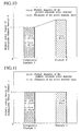
- Fig. 2 is a schematic sectional view showing a structure example of an active material layer in a positive electrode according to the embodiments of the present invention, which shows the active material layer where the porosity and the thickness are defined.
- Fig. 3 is a schematic sectional view showing a structure example of an active material layer in a positive electrode according to the embodiments of the present invention, which shows the active material layer having two layers of the different porosities.
- Fig. 4 is a schematic sectional view showing a structure example of an active material layer in a positive electrode according to the embodiments of the present invention, which shows the active material layer having two layers where the particle diameters of the positive electrode active materials are different.
- Fig. 5 is a graph showing the relation between the thickness of the active material layer (in the positive electrode) and the power density of the rechargeable lithium ion battery in each of example 1, comparative example 1 and comparative example 2.
- Fig. 6 is a graph showing the relation between the layer structure of the active material layer and the power density of the rechargeable lithium ion battery in each of example 2, example 3 and example 4.
- Fig. 7 is a graph showing the relation between the layer structure of the active material layer and the energy density of the rechargeable lithium ion battery in each of example 2, example 3 and example 4.
- Fig. 8 is a graph showing the relation between the layer structure of the active material layer and the power density of the rechargeable lithium ion battery in each of example 5 and example 6.
- Fig. 9 is a graph showing the relation between the layer structure of the active material layer and the energy density of the rechargeable lithium ion battery in each of example 5 and example 6.
- Fig. 10 is a graph showing the relation between the layer structure of the active material layer in the positive electrode and the power density of the rechargeable lithium ion battery in each of comparative example 3 and example 6.
- Fig. 11 is a graph showing the relation between the layer structure of the active material layer and the energy density of the rechargeable lithium ion battery in each of comparative example 3 and example 6.
- Fig. 12 is a graph showing the relation between the particle diameter of the positive electrode active material and the power density of the rechargeable lithium ion battery in each of example 7 and comparative example 4.
- Fig. 13 is a graph showing the relation between the thickness of the active material layer and the power density of the rechargeable lithium ion battery in each of example 8 and example 9.
-
- The rechargeable lithium ion battery according to embodiments of the present invention is a chargeable-dischargeable battery comprising a positive electrode and a negative electrode, which can be reversibly intercalated with lithium ion, and non-aqueous electrolyte exhibiting lithium ion conduction. The positive electrode and the negative electrode are separated by a separator to prevent them from contacting directly with each other to make a short circuit.
- Fig. 1 shows a structure example of the rechargeable lithium ion battery called a jerry roll type. As shown in Fig. 1, a wound device in a roll fashion, which includes a
positive electrode 10 with a positive electrode active material coated on both surfaces of a metal foil collector (i.e. a collecting electrode), anegative electrode 20 with a negative electrode material coated on both surfaces of a metal foil collector similarly, and aseparator 30 interposed between the both electrodes, is accommodated in acylindrical sealing case 40. An electrolyte (electrolytic solution) is filled between thepositive electrode 10 and thenegative electrode 20. - Other than the jerry roll type as shown in Fig. 1, there exists a structure in which the positive electrode, the separator and the negative electrode, which are shaped in sheets, are layered in order, as the rechargeable lithium ion battery
- As the positive electrode active material, lithium metal oxide, various types of widely known positive electrode active materials such as complex oxide in which a part of the lithium metal oxide is substituted with other elements and manganese oxide can be used appropriately. Specifically, as the lithium metal oxide, LiCoO2, LiNiO2, LiMnO2, LiMn2O4, LiXFeOY, LiXVYO2 and the like are listed. As the complex oxide in which a part of the lithium metal oxide is substituted with other elements, LiXCoYM2O2 (M is Mn, Ni, V or the like), LiXMnYM2O2 (M is Li, Ni, Cr, Fe, Co or the like) and the like are listed. As the manganese oxide, λ-MnO2, composite of MnO2 and V2O5, MnO2 · XV2O5(0<X≤0.3) as a ternary complex oxide, and the like are listed.
- As the negative electrode active material, carbon material such as hard carbon, soft carbon, graphite and activated carbon, and metal oxide such as SnBXPYO2, Nb2O5, LiTiXOY, LiFeXNY and LiMnXNY can be used singly or in a mixed state. Herein, the hard carbon means to the carbon material that is not graphitized when heat treatment is performed at 3000°C. The soft carbon means to the carbon material that is graphitized when heat treatment is performed at a range of 2800°C to 3000°C. Note that various well known technologies can be used for manufacturing the hard carbon, such as a method using furan resin, an organic material in which oxygen is bridged to petroleum pitch having an H/C atomic ratio at a range of 0.6 to 0.8 inclusively as a starting substance. And, for manufacturing the soft carbon, a method using coal, high polymer (polyvinyl chloride resin, polyvinyl acetate, polyvinyl butylate or the like), pitch or the like as the starting material can be used.
- As a method for fabricating the positive electrode by forming the active material layer on the collector, for example, a method of manufacturing the positive electrode is used, in which the positive electrode active material is mixed with a binder in a solvent to be in a paste state, and the paste is coated on the positive electrode collector, and dried.
- In addition, as a method for fabricating the negative electrode by forming the negative electrode active material layer on the negative electrode collector, a method in which the negative active material is mixed with a binder in a solvent to be in a paste state, and the paste is coated on the negative electrode collector, and dried, can be used. The paste is normally coated on the both sides of the collector. Note that a conductive substance such as carbon black, graphite and acetylene black may be added to the paste. It is preferable that the mixing ratio of the active material and the binder is appropriately determined for the shape of the electrode.
- As the collector, various material used in the rechargeable lithium ion battery can be used. Specifically, an aluminum foil and a copper foil are listed as the positive electrode collector and the negative electrode collector respectively.
- Polyvinylidene fluoride (PVDF), polytetrafluoroethylene and the like can be listed as the binder, and various kinds of a polar solvent can be used as the solvent. Specifically, dimethylformamide, dimethylacetamide, methylformamide, N-methylpyrrolidone (NMP) and the like can be listed. Note that N-methylpyrrolidone is preferably used when polyvinylidene fluoride is used as the binder.
- As the non-aqueous electrolytic solution, various kinds of solvent exhibiting lithium ion conduction are preferable, where cyclic ester carbonate such as ethylene carbonate (EC), propylene carbonate (PC) and butylene carbonate (BC) can be used singly or by appropriately mixing them. Moreover, to increase the electric conductivity and to obtain the electrolytic solution having an appropriate viscosity, dimethyl carbonate (DMC), diethyl carbonate (DEC), γ-butyrolactone, γ-valerolactone, ethyl acetate, methyl propionate and the like can be used in combination.
- LiPF6, LiBF4, LiClO4, LiAsF6, LiCF3SO4 and the like can be listed as the electrolyte in the non-aqueous electrolytic solution.
- A micro porous film of polyolefin based resin such as polyethylene and polypropylene can be used as the separator.
- The rechargeable lithium ion battery according to this embodiment can be manufactured by appropriately combining the above-described positive electrode, negative electrode, non-aqueous electrolytic solution and separator. In addition, various kinds of substance and shape can be applied for the battery canister, the battery shape and the like.
- Next, a first feature of the rechargeable lithium ion battery according to this embodiment will be explained.
- As shown in Fig. 2A, the rechargeable lithium ion battery according to this embodiment has a positive electrode comprising a collector 30 (i.e. a collecting electrode) and an
active material layer 20 formed on thecollector 30. Theactive material layer 20 contains positive electrodeactive material 10. The particle diameter of the positive electrodeactive material 10 is set to 5 µm or less, and more preferably to 1 µm or less, and the thickness of theactive material layer 20 is set to a range of 20 to 80 µm, and more preferably to at a range of 20 to 30 µm. - For example, the
active material layer 20 is obtained by mixing various kinds of component such as the positive electrodeactive material 10 and the binder in the solvent to make paste, coating the past on the surface of thecollector 30 and drying the coated paste. When the active material layers are formed on the both sides of thecollector 30 according to a normal method, each of the active material layers is made to be an independent active material layer. Further, the particle diameter of the positive electrodeactive material 10 means an average particle diameter. - Moreover, in the rechargeable lithium ion battery the surface of the
active material layer 20 substantially contacts aseparator 40, and void portions in the active material layer are filled withelectrolytic solution 50. The positive electrode and the negative electrode are reversibly intercalated with lithium ions. At the time of discharging the rechargeable lithium ion battery lithium ions migrate to the positive electrode via the electrolytic solution from the negative electrode. - If the particle diameter of the positive electrode
active material 10 is large, lithium ion diffusion in the positive electrodeactive material 10 particle is in a rate-determining step at the time of discharging a large current rather than the migration of lithium ion in theelectrolytic solution 50 in the electrode in the layer thickness direction of the active material layer, which is a cause for the power density reduction. Accordingly, it is preferable that the particle diameter of the positive electrodeactive material 10 is 5 µm or less. Although the lowest limit value of the particle diameter of the positive electrodeactive material 10 is not particularly limited, 0.1 µm or more is appropriate practically. In addition, if the thickness of theactive material layer 20 is smaller than 20 µm, the power density becomes small due to shortage of the positive electrode active material amount, which is not preferable. On the other hand, if the thickness exceeds 80 µm, internal resistance is increased and the power density becomes small, which is also not preferable. - Under the condition that the particle diameter of the positive electrode
active material 10 is small such that the particle diameter of the positive electrodeactive material 10 is 5 µm or less, the migration of lithium ion in theelectrolytic solution 40 in the electrode in the layer thickness direction is considered to be in the rate-determining step at the time of discharging the large current. Accordingly, if the porosity of theactive material layer 20 becomes large, the electrolytic solution amount in the electrode increases and the migration power of lithium ion in the electrolytic solution in the electrode in the layer thickness direction increases. Thus, the power density is further increased. However, if the porosity of theactive material layer 20 is less than 50%, the electrolytic solution amount cannot be secured in accordance with the amount of the positive electrodeactive material 10. Thus the resistance increases to reduce the power density. Therefore, the porosity of theactive material layer 20 is preferably 50% or more. In addition, if the porosity exceeds 60%, shortage of the amount of the positive electrodeactive material 10, that is, reduction of a positive electrode surface area makes the power density gradually reduced. Accordingly, the porosity is more preferably at a range of 50 to 60%. - On the contrary, under the condition that the particle diameter of the positive electrode
active material 10 is larger than 5 µm, the lithium ion diffusion in the positive electrodeactive material 10 is in the rate-determining step. Therefore, the power density cannot be increased even if the porosity is raised to increase the amount of theelectrolytic solution 50 in the electrode. The power density is rather decreased because the amount of the positive electrodeactive material 10 is reduced. - As described above, the thickness of the
active material layer 20 is preferably 20 µm or more to increase the power density by defining the porosity of theactive material layer 20. This is because the influence of the lithium ion migration in theelectrolytic solution 50 in the electrode in the layer thickness direction and the porosity is small when the layer thickness is thin. - The
active material layer 20 may have a structure where a plurality of active material layers having different porosities are layered. For example, as shown in Fig. 3, theactive material layer 20 may have a two layer structure havingactive material layers active material layer 20B closer to the separator is made larger and the porosity of theactive material layer 20A closer to the collector is made smaller. The amount of theelectrolytic solution 50 in the vicinity of theseparator 40 can be increased and the migration power of lithium ion can be increased by making the porosity of theactive material layer 20B adjacent to theseparator 40 large. Moreover, a usage rate of the positive electrodeactive material 10 in the vicinity of thecollector 30 can be increased by making the porosity in the vicinity of thecollector 30 small. Considering the above characteristics, the power density can be effectively increased by balancing the diffusion in the positive electrodeactive material 10 and the migration in theelectrolytic solution 50. Since the energy density is influenced by an average porosity and the active material amount of theactive material layer 20, the power density can be increased without sacrificing the energy density by appropriately adjusting the average porosity and the amount of the active material. For example, an electrode having the single active material layer of the porosity of 50% and the thickness of 60 µm, and an electrode that consists of a layered active material layer, which has a first active material layer of the porosity of 40% and the thickness of 30 µm closer to the collector and a second active material layer of the porosity of 60% and the thickness of 30 µm closer to the separator, have the equal energy density. This is because the average porosities and the amounts of the active material of the two electrodes are equal. - As shown in Fig. 3, in the case where the electrode includes two
active material layers active material layers active material layers active material layers active material layer 20A closer to thecollector 30 increases if less than 30 µm. The porosity of theactive material layer 20A closer to thecollector 30 is preferably 30% or more and less than 50%, and more preferably 40% or more and less than 50%. The porosity of theactive material layer 20B closer to the separator is preferably at a range of 50% to 60%, and more preferably at a range of 50% to 55%. More effect can be obtained by adjusting the porosity within the above ranges. - Next, a second feature of the rechargeable lithium ion battery according to this embodiment of the present invention will be explained.
- As shown in Fig.4, the rechargeable lithium ion battery according to this embodiment comprises
active material layers active materials 10A and 10B with the different particle diameters in the positive electrode. The power density can be increased by this constitution. - Generally, the migration of lithium ion in the electrolytic solution in the electrode in the layer thickness direction of the active material layer tends to be in the rate-determining step at the time of discharging the large current. Accordingly, sufficient lithium ion does not reach the vicinity of the collector, the positive electrode active material cannot be utilized effectively, and thus the power density tends to be reduced.
- To solve this problem it is preferable that the particle diameter of the positive electrode active material near the
separator 40 is made to be larger. Accordingly, the electrode surface area near theseparator 40 is reduced, the usage rate of the positive electrode active material near theseparator 40 is reduced, and thus lithium ion can migrate more easily to the vicinity of thecollector 30. As a result, the usage rate of the positive electrode active material near thecollector 30 increases, and the usage rate of the electrode active material is totally increased, thus increasing the power density. The amount of the positive electrode active material is appropriately adjusted such that the total amounts in the active material layer of the single layer structure and in the active material layer of the two layer structure become equal, and thus the power density can be increased without sacrificing the energy density. - The advantage from adopting the active material layer of the two layer structure exhibits when the particle diameter of the positive electrode active material 10B near the
separator 40 is so large that the usage rate of the positive electrode active material near theseparator 40 is reduced. Therefore, if the thickness of theactive material layer 21B closer to theseparator 40 is thicker than required, the usage rate of the positive electrode active material 10B near theseparator 40 is increased. Thus, the advantage of the two layer structure becomes small, which is not preferable. The power density is also reduced if the thickness of theactive material layer 21A closer to thecollector 30 is thicker than required, which is not preferable. Therefore, the thickness of each layer is preferably 30 µm or less, and more preferably 25 µm or less. The lowest limit value of the thickness of each active material layer is preferably 20 µm in order to prevent reduction of the energy density. This is because the weight ratio of the collector and the like in the battery becomes large if the thickness of the active material layer is less than 20 µm. - Moreover, if the particle diameter of the
active material layer 21A closer to thecollector 30 is 5 µm or more, or if the active material particle diameter of theactive material layer 21B closer to theseparator 40 is less than 5 µm, the effect of increasing the power density becomes small, which is not preferable. The lowest limit value of particle diameter r1 of the positive electrodeactive material 10A closer to thecollector 30 is not particularly limited. But, it is practically appropriate that the value is 0.1 µm or more. It is preferable that the upper limit of the particle diameter of the positive electrode active material 10B of theactive material layer 20B closer to theseparator 40 is appropriately selected in a range where the active material particle diameter does not become larger than the thickness of the active material layer. From the above viewpoint, the particle diameter of the positive electrodeactive material 10A of theactive material layer 21A closer to thecollector 30 is preferably 0.1 µm or more and less than 5 µm, and more preferably 1 µm or more and less than 5 µm. The particle diameter of the positive electrode active material of theactive material layer 21B closer to theseparator 40 is preferably at a range of 5 µm to 20 µm inclusively, and more preferably at a range of 5 µm to 10 µm. - Note that the particle diameter of the positive electrode active material can be adjusted by the particle diameter of the starting material or classification thereof, and the porosity of the active material layer can be adjusted by changing pressure when pressing the layer after the paste containing the positive electrode active material and the conductive material is coated on the collector and dried.
- In the above description, the two layer structure is mainly explained, however, the similar effect can be obtained by adjusting the porosity of the active material layer, the particle diameter of the active material and the thickness of the active material layer even if the layer structure has a multi-layer structure of three layers or more..
- In the case of adopting the multi-layer structure, coating can be sequentially formed to n-th layer by a method in which a first layer is coated on the collector and a second layer is coated thereon. Alternatively, the multi-layer structure also can be formed by utilizing the difference of the sedimentation velocity of the particles of the different sizes.
- In the rechargeable lithium ion battery of this embodiment described above, it is preferable that the positive electrode active material is lithium manganese oxide from the viewpoint of obtaining a high power density. Since manganese is much more inexpensive than cobalt and nickel and abundant as resource, it is also preferable from the viewpoint of a manufacturing cost. Specific example of the lithium manganese oxide, LiMnO2 and LiMn2O4 are listed.
- In order to increase the power density in the rechargeable lithium ion battery of this embodiment, the electrolyte concentration of the non-aqueous electrolytic solution is preferably at a range of 1.0 to 3.0 mol/l, and more preferably at a range of 1.5 to 2.5 mol/l. By using the electrolytic concentration in the above ranges, the diffusion in the active material and the migration in the electrolytic solution are balanced and the preferable power density can be obtained.
- When the particle diameter of the positive electrode active material is small, or when the porosity of the active material layer is large, the migration of lithium ion in the electrolytic solution in the electrode in the layer thickness direction is in the rate-determining step at the time of discharging the large current. Accordingly, if the electrolyte concentration is made large, concentration polarization is controlled and the migration power of lithium ion in the electrolytic solution in the electrode in the layer thickness direction increases, thus the power density increases. If the electrolyte concentration exceeds 3.0 mol/l, influence of the lithium ion conductance of the electrolytic solution emerges to reduce the power density, which is not preferable. And, if the electrolyte concentration is less than 1.0 mol/l, the internal resistance of the battery increases, which is also not preferable. A voltage at the time of discharging can be held at a high level and stabilized by adjusting the electrolyte concentration at the range of 1.5 to 2.5 mol/l.
- The relation between the particle diameter of the positive electrode active material and the electrolyte concentration could also influence the power density. Specifically, when the particle diameter of the positive electrode active material is larger than 5 µm, lithium ion diffusion in the positive electrode active material particle is in a rate-determining step at the time of discharging the large current rather than the migration of lithium ion in the electrolytic solution in the electrode in the layer thickness direction. Accordingly, the influence of the concentration of the electrolytic solution is small, and the power density does not increase as expected even if the electrolyte concentration is increased. Therefore, when the active material layer is formed in the multi-layer structure of two layers or more, it is preferable that the active material particle diameter of the active material layer closer to the collector is made to be less than 5 µm.
- In addition, the electrolyte is preferably LiPF6 or LiBF4 from the viewpoint that the power density is increased by using a compound having high electrical conductivity.
- Note that the particle diameter of the positive electrode active material, the porosity and the thickness of the active material layer can be measured by a method measuring various particle distribution such as a screening test and a sedimentation method, a specific gravity of constituent substance, and a micrometer, respectively.
- As described above, in the rechargeable lithium ion battery of this embodiment, the high power density can be obtained while maintaining the energy density. Therefore, it can be utilized best as a power source of the electric vehicle and the hybrid vehicle.
- Lithium manganese oxide (LiMnO2) having the average particle diameter of 3 µm was used as the positive electrode active material. The specific surface area of the positive electrode active material was about 3 m2/g. 75 wt% of the positive electrode active material, 10 wt% of acetylene black as the conductive material and 15wt% of PVDF as the binder were mixed in NMP and coated on the aluminum foil (collector). Thus, a plurality of positive electrodes having the different porosities of the active material layers in the thickness of the active material layer of 60 µm were fabricated. The porosity was adjusted by the amount of the solvent, drying conditions and the pressing of the electrode. Metal lithium was used for the negative electrode active material, and a mixture of PC and DMC (volume ratio 1:1), in which 1M of LiPF6 was dissolved, was used as the electrolytic solution. Thus, a plurality of the rechargeable lithium batteries having the different porosities of the active material layers were fabricated.
- A plurality of the rechargeable lithium batteries having the different porosities were fabricated by using the same conditions as those of Example 1 except that the average particle diameter of the positive electrode active material is 30 µm.
- A plurality of the rechargeable lithium batteries having the different porosities were fabricated by using the same conditions as those of Example 1 except that the thickness of the active material layer is 10 µm.
- Fig. 5 shows the relation between the porosity of the active material layer and the power density (a relative value when setting the power density at 40% of the porosity as 1) of the rechargeable lithium ion battery in each of Example 1, Comparative example 1 and Comparative example 2. The power density of the battery of Example 1 reached the maximum value at a range of 50 to 60% of the porosity, while the power density of the batteries of Comparative examples 1 and 2 are reduced as the porosities became larger.
- The lithium manganese oxide (LiMnO2) having the average particle diameter of 3 µm was used as the positive electrode active material. The specific surface area of the positive electrode active material was about 3 m2/g. 75wt% of the positive electrode active material, 10wt% of acetylene black as the conductive material and 15wt% of PVDF as the binder were mixed in NMP and coated on the aluminum foil (collector). Thus, a first active material layer having the porosity of 40% and the thickness of 30 µm was formed. Moreover, a second active material layer having the porosity of 60% and the thickness of 30 µm in the same composition was layered on the first active material layer. The porosity was adjusted by the amount of the solvent, the drying conditions and the pressing of the electrode. The rechargeable lithium ion battery was fabricated by using the positive electrode having the two active material layers of the different porosities, which were fabricated as described above, the negative electrode containing the negative electrode active material, which consists of the metal lithium, and the electrolytic solution that consists of the mixture of PC and DMC (volume ratio 1:1) dissolving 1M of LiPF6 therein.
- The lithium manganese oxide (LiMnO2) having the average particle diameter of 3 µm was used as the positive electrode active material. The specific surface area of the positive electrode active material was about 3 m2/g. 75wt% of the positive electrode active material, 10wt% of acetylene black as the conductive material and 15wt% of PVDF as the binder were mixed in NMP and coated on the aluminum foil (collector). Thus, the positive electrode having the 50% porosity of the active material layer and the 60 µm thickness of the active material layer was fabricated. The porosity was adjusted by the amount of the solvent, the drying conditions and the pressing of the electrode. The rechargeable lithium ion battery was fabricated by using the positive electrode fabricated as described above, the negative electrode active material that consists of the metal lithium, and the electrolytic solution that consists of the mixture of PC and DMC (volume ratio 1:1) dissolving 1M of LiPF6 therein.
- The lithium manganese oxide (LiMnO2) having the average particle diameter of 3 µm was used as the positive electrode active material. The specific surface area of the positive electrode active material was about 3 m2/g. 75wt% of the positive electrode active material, 10wt% of acetylene black as the conductive substance and 15wt% of PVDF as the binder were mixed in NMP and coated on the aluminum foil (collector). Thus, the first active material layer having the porosity of 40% and the thickness of 20 µm was formed. Moreover, the second active material layer having the porosity of 60% and the thickness of 40 µm in the same composition was layered on the first active material layer. The porosity was adjusted by the amount of the solvent, the drying conditions and the pressing of the electrode. Thus, the positive electrode having the active material layer of the two layer structure with the total thickness of 60 µm was fabricated. The rechargeable lithium ion battery was fabricated by using this positive electrode, the negative electrode using the negative electrode active material that consists of the metal lithium, and the electrolytic solution that consists of the mixture of PC and DMC (volume ratio 1:1) dissolving 1M of LiPF6 therein.
- Fig. 6 shows the power density (a relative value when setting the power density of Example 3 as 1) of the battery in each of Examples 2 to 4. The power density increased by allowing the active material layer to have the two layer structure. In addition, in the case of the two layer structure, the power density could be increased more effectively when the thickness of each active material layer is set at 30 µm or less.
- Next, Fig. 7 shows the energy density (a relative value when setting the energy density of Example 3 as 1) of the battery in each of Examples 2 to 4. The energy densities of Examples 2 and 3 were equal. This is because the average porosities of Examples 2 and 3, and the amounts of the positive electrode active material of Examples 2 and 3 are equal severally. Although the power density of Example 4 increased in comparison with Example 3 having the active material layer of the single layer structure, the energy density was smaller.
- Two kinds of the lithium manganese oxide (LiMnO2) having the average particle diameter of 3 µm and 9 µm were used as the positive electrode active material. 75wt% of the positive electrode active material with the average particle diameter of 3 µm, 10wt% of acetylene black as the conductive substance and 15wt% of PVDF as the binder were mixed in NMP and coated on the aluminum foil (collector). Thus, the first active material layer having the thickness of 30 µm was fabricated. The second active material layer having the thickness of 30 µm, which was fabricated in the same method by using the positive electrode active material having the average particle diameter of 9 µm, was layered on the first active material layer. The positive electrode having the active material layer of the two layer structure with the thickness of 60 µm was thus fabricated. The rechargeable lithium ion battery was fabricated by using this positive electrode, the negative electrode containing the negative electrode active material that consists of the metal lithium, and the electrolytic solution that consists of the mixture of PC and DMC (volume ratio 1:1) dissolving 1M of LiPF6 therein.
- The positive electrode having the active material layer of the single layer structure with the thickness of 50 µm was fabricated in the same method as that of Example 5 by using the lithium manganese oxide (LiMnO2) having the average particle diameter of 3 µm as the positive electrode active material. The rechargeable lithium ion battery was fabricated by using the positive electrode, the negative electrode containing the negative electrode active material, which consists of the metal lithium, and the electrolytic solution that consists of the mixture of PC and DMC (volume ratio 1:1) dissolving 1M of LiPF6 therein.
- Fig. 8 shows the power density (a relative value when setting the power density of Example 6 as 1) in each of Examples 5 and 6. Example 5 having the active material layer of the two layer structure in which each layer has the different particle diameter shows the higher power density. In addition, Fig. 9 shows the energy density (a relative value when setting the energy density of Example 6 as 1) in each of Examples 5 and 6. The energy densities of Examples 5 and 6 were equal. This is because the amounts of the positive electrode active material of Examples 5 and 6 are equal.
- Two kinds of the lithium manganese oxide (LiMnO2) having the average particle diameters of 3 µm and 9 µm were used as the positive electrode active material. 75wt% of the positive electrode active material with the average particle diameter of 3 µm, 10wt% of acetylene black as the conductive substance and 15wt% of PVDF as the binder were mixed in NMP and coated on the aluminum foil (collector). Thus, the first active material layer having the thickness of 20 µm was fabricated. The second active material layer having the thickness of 40 µm, which was fabricated in the same method by using the positive electrode active material having the average particle diameter of 9 µm, was layered on the first active material layer. The positive electrode having the active material layer of the two layer structure with the thickness of 60 µm was thus fabricated.
- The rechargeable lithium ion battery was fabricated by using the positive electrode, the negative electrode containing the negative electrode active material that consists of the metal lithium, and the electrolytic solution that consists of the mixture of PC and DMC (volume ratio 1:1) dissolving 1M of LiPF6 therein.
- Fig. 10 shows the power density (a relative value when setting the power density of Comparative example 3 as 1) in each of Comparative example 3 and Example 6. The power density of Comparative example 3 is low because the usage rate of the active material near the separator is reduced due to the large particle diameter of the positive electrode active material closer to the separator and the usage rate of the positive electrode active material near the collector was also reduced since the thickness of the active material layer closer to the separator was thick. In addition, Fig. 11 shows the energy density (a relative value when setting the energy density of Comparative example 3 as 1) in each of Comparative example 3 and Example 6. The specific energies of Comparative example 3 and Example 6 were equal. This is because the amounts of the positive electrode active material of Comparative example 3 and Example 6 are equal.
- The lithium manganese oxide (LiMnO2) having the average particle diameter of 3 µm was used as the positive electrode active material. 75% by weight of the positive electrode active material with the average particle diameter of 3 µm, 10% by weight of acetylene black as the conductive substance and 15% by weight of PVDF as the binder were mixed in NMP and coated on the aluminum foil (collector). Thus, the positive electrode having the active material layer with the thickness of 30 µm was fabricated. A plurality of the rechargeable lithium batteries were fabricated by using this positive electrode, the negative electrode containing the negative electrode active material, which consists of the metal lithium, and the electrolytic solution that consists of the mixture of PC and DMC (volume ratio 1:1) dissolving LiPF6 with the different concentrations therein.
- A plurality of the rechargeable lithium batteries were fabricated by using the same conditions as those of Example 7 except that the lithium manganese oxide (LiMnO2) with the average particle diameter of 30 µm was used as the positive electrode active material.
- Fig. 12 shows the relation between the electrolyte concentration and the power density (a relative value when setting the power density at the time of 1 mol/l of the electrolyte concentration as 1) in each of Example 7 and Comparative example 4. Example 7 had the maximum power density when the electrolyte concentration was 2 mol/l. On the contrary, Comparative example 4 did not show the power density increase even after the electrolyte concentration was increased.
- The lithium manganese oxide (LiMnO2) having the average particle diameter of 3 µm was used as the positive electrode active material. 75wt% of the positive electrode active material, 10wt% of acetylene black as the conductive substance and 15wt% of PVDF as the binder were mixed in NMP and coated on the aluminum foil (collector). Thus, a plurality of the positive electrodes having the active material layers with the different thicknesses were fabricated. A plurality of the rechargeable lithium batteries were fabricated by using these positive electrodes, the negative electrode containing the negative electrode active material, which consists of the metal lithium, and the electrolytic solution that consists of the mixture of PC and DMC (volume ratio 1:1) dissolving LiBF4 with the concentration of 2 mol/l therein.
- The rechargeable lithium ion battery was fabricated by using the same method as that of Example 8 except that LiBF4 with the concentration of 1 mol/l was used as the electrolytic solution.
- Fig. 13 shows the relation between the thickness of the active material layer and the power density (a relative value when setting the power density at the time of 100 µm in the layer thickness of Example 9 as 1) of Examples 8 and 9. As shown in Fig.13, when the thickness of the active material layer is 20 - 80 µm, preferably 20- 60 µm, high power densities are obtained. The power density of Example 8 having the preferable electrolyte and the electrolyte concentration was twice as high as that of Example 9.
- The entire contents of Japanese Patent Application P2000-257766 (filed August 28, 2000) are incorporated herein by reference. Although the inventions have been described above by reference to certain embodiments of the inventions, the inventions are not limited to the embodiments described above. Modifications and variations of the embodiments described above will occur to those skilled in the art, in light of the above teachings.
- The scope of the inventions is defined with reference to the following claims.
Claims (14)
- A rechargeable lithium ion battery which is capable of using as an energy source for a vehicle, comprising:(a)a positive electrode comprising:a collecting electrode; andan active material layer which is formed on the collecting electrode, contains a positive electrode active material,wherein thickness of the active material layer is at a range of 20 - 80 µm;particle diameter of the positive electrode active material is Sum or less; andporosity of the active material layer is 50% or more,(b)a negative electrode; and(c)a non-aqueous electrolytic solution.
- The rechargeable lithium ion battery according to claim 1,
wherein the thickness of the active material layer is at a range of 20 - 60 µm. - The rechargeable lithium ion battery according to claim 1,
wherein the active material layer has a porosity at a range of 50% to 60%. - The rechargeable lithium ion battery according to any of claims 1 to 3,
wherein the active material layer comprises of a plurality of active material layers having different porosities. - The rechargeable lithium ion battery according to claim 4,
wherein the porosity of the active material layer closer to the collecting electrode is lower. - The rechargeable lithium ion battery according to claim 1,
wherein the active material layer includes a first active material layer formed on the collecting electrode and a second active material layer formed on the first active material layer,the first and second active material layers severally have thickness at a range of 20 µm to 30 µm,a porosity of the first active material layer is 30% or more and less than 50%, anda porosity of the second active material layer is at a range of 50% to 60%. - A rechargeable lithium ion battery which is capable of using as an energy source for a vehicle, comprising:(a)a positive electrode comprising:a collecting electrode; andtwo active material layers which are formed on the collecting electrode, each of which contains a positive electrode active material with a different particle diameter and has a thickness at a range of 20 to 30 µm inclusively;(b)a negative electrode; and(c)a non-aqueous electrolytic solution.
- The rechargeable lithium ion battery according to claim 7,
wherein the active material layer includes a first active material layer formed on the collecting electrode and a second active material layer formed on the first active material layer,the first active material layer contains a positive electrode active material having a particle diameter of 0.1 µm or more and less than 5 µm, andthe second active material layer contains a positive electrode active material having a particle diameter at a range of 5 µm to 20 µm. - The rechargeable lithium ion battery according to any of claims 1 to 8,
wherein the positive electrode active material is lithium manganese oxide. - The rechargeable lithium ion battery according to any of claims 1 to 9,
wherein the non-aqueous electrolytic solution has the concentration of electrolyte at a range of 1.0 mol/l to 3.0 mol/l. - The rechargeable lithium ion battery according to any of claims 1 to 10,
wherein the non-aqueous electrolytic solution has the concentration of electrolyte at a range of 1.5 mol/l to 2.5 mol/l. - The rechargeable lithium ion battery according to any of claims 1 to 11,
wherein the electrolyte is one of LiPF6 and LiBF4 - A vehicle, comprising:a rechargeable lithium ion battery, comprising:wherein thickness of the active material layer is at a range of 20 - 80 um;(a)a positive electrode comprising:a collecting electrode; andan active material layer which is formed on the collecting electrode, contains a positive electrode active material,particle diameter of the positive electrode active material is Sum or less; andporosity of the active material layer is 50% or more;(b)a negative electrode; and(c)a non-aqueous electrolytic solution.
- A vehicle, comprising:a rechargeable lithium ion battery, comprising:(a)a positive electrode comprising:a collecting electrode; andtwo active material layers which are formed on the collecting electrode, each of which contains a positive electrode active material with a different particle diameter and has a thickness at a range of 20 to 30 µm inclusively;(b)a negative electrode; and(c)a non-aqueous electrolytic solution.
Applications Claiming Priority (2)
| Application Number | Priority Date | Filing Date | Title |
|---|---|---|---|
| JP2000257766 | 2000-08-28 | ||
| JP2000257766 | 2000-08-28 |
Publications (3)
| Publication Number | Publication Date |
|---|---|
| EP1184918A2 true EP1184918A2 (en) | 2002-03-06 |
| EP1184918A3 EP1184918A3 (en) | 2007-04-04 |
| EP1184918B1 EP1184918B1 (en) | 2009-10-14 |
Family
ID=18746184
Family Applications (1)
| Application Number | Title | Priority Date | Filing Date |
|---|---|---|---|
| EP01119929A Expired - Lifetime EP1184918B1 (en) | 2000-08-28 | 2001-08-17 | Rechargeable lithium ion battery |
Country Status (3)
| Country | Link |
|---|---|
| US (1) | US7138208B2 (en) |
| EP (1) | EP1184918B1 (en) |
| DE (1) | DE60140163D1 (en) |
Cited By (13)
| Publication number | Priority date | Publication date | Assignee | Title |
|---|---|---|---|---|
| EP1443574A1 (en) * | 2003-01-28 | 2004-08-04 | Nissan Motor Co., Ltd. | Electrode for secondary battery having instrinsic polymer electrolyte, method of producing the same, and secondary battery |
| EP1544935A1 (en) * | 2003-01-28 | 2005-06-22 | Nissan Motor Co., Ltd. | Electrode for secondary battery having gel polymer electrolyte, method of producing the same, and secondary battery |
| WO2008153749A1 (en) * | 2007-05-25 | 2008-12-18 | Massachusetts Institute Of Technology | Batteries and electrodes for use thereof |
| CN101300695B (en) * | 2005-11-10 | 2010-08-11 | 日产自动车株式会社 | Electrode for secondary battery and secondary battery using same |
| US7988746B2 (en) | 2000-10-20 | 2011-08-02 | A123 Systems, Inc. | Battery structures, self-organizing structures and related methods |
| US8088512B2 (en) | 2001-07-27 | 2012-01-03 | A123 Systems, Inc. | Self organizing battery structure method |
| US8148009B2 (en) | 2000-10-20 | 2012-04-03 | Massachusetts Institute Of Technology | Reticulated and controlled porosity battery structures |
| US8481208B2 (en) | 2002-07-26 | 2013-07-09 | A123 Systems, LLC | Bipolar articles and related methods |
| EP2843733A1 (en) * | 2013-09-03 | 2015-03-04 | Samsung SDI Co., Ltd. | Electrode for rechargeable lithium battery and rechargeable lithium battery including the same |
| US8999571B2 (en) | 2007-05-25 | 2015-04-07 | Massachusetts Institute Of Technology | Batteries and electrodes for use thereof |
| US10164242B2 (en) | 2011-04-07 | 2018-12-25 | Massachusetts Institute Of Technology | Controlled porosity in electrodes |
| US10569480B2 (en) | 2014-10-03 | 2020-02-25 | Massachusetts Institute Of Technology | Pore orientation using magnetic fields |
| US10675819B2 (en) | 2014-10-03 | 2020-06-09 | Massachusetts Institute Of Technology | Magnetic field alignment of emulsions to produce porous articles |
Families Citing this family (73)
| Publication number | Priority date | Publication date | Assignee | Title |
|---|---|---|---|---|
| JP4037229B2 (en) * | 2002-09-30 | 2008-01-23 | 日立マクセル株式会社 | Lithium secondary battery electrode and lithium secondary battery using this as a negative electrode |
| KR100508925B1 (en) * | 2003-07-01 | 2005-08-17 | 삼성에스디아이 주식회사 | Polymer electrolyte for rechargeable lithium battery and rechargeable lithium battery comprising same |
| WO2005006469A1 (en) * | 2003-07-15 | 2005-01-20 | Itochu Corporation | Current collecting structure and electrode structure |
| UA67135A (en) * | 2003-07-25 | 2004-06-15 | Subsidiary Entpr With Foreign | Method for producing lithium battery |
| WO2005013400A2 (en) * | 2003-07-31 | 2005-02-10 | Nissan Motor Co., Ltd. | Secondary cell electrode and fabrication method, and secondary cell, complex cell, and vehicle |
| JP4055671B2 (en) * | 2003-07-31 | 2008-03-05 | 日産自動車株式会社 | Non-aqueous electrolyte battery |
| US20050053834A1 (en) * | 2003-09-04 | 2005-03-10 | Advanced Battery Technology, Ltd. | Positive electrode material and method |
| JP3987851B2 (en) * | 2003-12-04 | 2007-10-10 | 三井金属鉱業株式会社 | Secondary battery negative electrode and secondary battery including the same |
| JP4763995B2 (en) * | 2004-01-07 | 2011-08-31 | 三井金属鉱業株式会社 | Nonaqueous electrolyte secondary battery electrode |
| CN102751488B (en) * | 2004-02-06 | 2016-05-25 | A123系统有限责任公司 | There is the lithium secondary battery of high charge and discharge rate capability |
| US8617745B2 (en) * | 2004-02-06 | 2013-12-31 | A123 Systems Llc | Lithium secondary cell with high charge and discharge rate capability and low impedance growth |
| JP4693373B2 (en) * | 2004-07-21 | 2011-06-01 | 三洋電機株式会社 | Non-aqueous electrolyte battery |
| JP2006032280A (en) * | 2004-07-21 | 2006-02-02 | Sanyo Electric Co Ltd | Nonaqueous electrolyte battery |
| KR100682862B1 (en) * | 2005-01-11 | 2007-02-15 | 삼성에스디아이 주식회사 | Electrode for electrochemical cell, manufacturing method thereof, and electrochemical cell containing the electrode |
| US20060240290A1 (en) * | 2005-04-20 | 2006-10-26 | Holman Richard K | High rate pulsed battery |
| KR100908571B1 (en) * | 2005-11-15 | 2009-07-22 | 주식회사 엘지화학 | Lithium secondary battery with excellent safety and low temperature output characteristics |
| CA2534243A1 (en) * | 2006-01-25 | 2007-07-25 | Hydro Quebec | Coated metal oxide particles with low dissolution rate, methods for their preparation and use in electrochemical systems |
| US8771877B2 (en) * | 2006-12-28 | 2014-07-08 | Gs Yuasa International Ltd. | Positive electrode material for nonaqueous electrolyte secondary battery, nonaqueous electrolyte secondary battery including the same, and method for producing the same |
| JP4513822B2 (en) * | 2007-03-30 | 2010-07-28 | Tdk株式会社 | Electrode and electrochemical device |
| JP2008300302A (en) * | 2007-06-04 | 2008-12-11 | Panasonic Corp | Nonaqueous secondary battery, and manufacturing method of positive electrode for nonaqueous electrolyte secondary battery |
| JP2008311164A (en) * | 2007-06-18 | 2008-12-25 | Panasonic Corp | Nonaqueous electrolyte secondary battery and manufacturing method of electrode for nonaqueous electrolyte secondary battery |
| JP5167703B2 (en) * | 2007-06-20 | 2013-03-21 | 日産自動車株式会社 | Battery electrode |
| JP5795475B2 (en) * | 2007-07-25 | 2015-10-14 | エルジー・ケム・リミテッド | Electrochemical element and manufacturing method thereof |
| DE102007058197B4 (en) * | 2007-12-04 | 2017-12-28 | Dr. Ing. H.C. F. Porsche Aktiengesellschaft | hybrid vehicle |
| JP4403524B2 (en) * | 2008-01-11 | 2010-01-27 | トヨタ自動車株式会社 | Electrode and manufacturing method thereof |
| JP4778034B2 (en) * | 2008-01-30 | 2011-09-21 | パナソニック株式会社 | Method for producing non-aqueous secondary battery |
| US20100035141A1 (en) * | 2008-08-11 | 2010-02-11 | Victor Grosvenor | Enhanced Electrolyte Percolation in Lithium Ion Batteries |
| WO2010074299A1 (en) * | 2008-12-24 | 2010-07-01 | 日本碍子株式会社 | Plate-shaped particles for positive electrode active material of lithium secondary batteries, and lithium secondary batteries |
| EP2396840A1 (en) | 2009-02-10 | 2011-12-21 | Fraunhofer-Gesellschaft zur Förderung der angewandten Forschung e.V. | Power-optimized and energy-density-optimized flat electrodes for electrochemical energy stores |
| EP2287945A1 (en) * | 2009-07-23 | 2011-02-23 | Fraunhofer-Gesellschaft zur Förderung der angewandten Forschung e.V. | Electrodes for electrochemical energy storage devices with optimised output and energy storage |
| KR101147602B1 (en) * | 2009-03-03 | 2012-05-21 | 주식회사 엘지화학 | Lithium Secondary Battery Containing Cathode Materials Having High Energy Density and Organic/Inorganic Composite Porous Membrane |
| JP5448001B2 (en) * | 2009-08-04 | 2014-03-19 | トヨタ自動車株式会社 | Non-aqueous electrolyte type lithium ion secondary battery |
| US20110168550A1 (en) * | 2010-01-13 | 2011-07-14 | Applied Materials, Inc. | Graded electrode technologies for high energy lithium-ion batteries |
| JP2012048959A (en) * | 2010-08-26 | 2012-03-08 | Sanyo Electric Co Ltd | Electrode for nonaqueous electrolyte secondary battery and nonaqueous electrolyte secondary battery |
| CN103155238B (en) * | 2010-10-15 | 2015-07-15 | 丰田自动车株式会社 | Secondary battery |
| JP5377472B2 (en) * | 2010-12-24 | 2013-12-25 | 日立ビークルエナジー株式会社 | Lithium ion secondary battery |
| EP2706599B1 (en) | 2011-05-06 | 2021-03-03 | Toyota Jidosha Kabushiki Kaisha | Lithium ion secondary cell |
| GB2492167C (en) | 2011-06-24 | 2018-12-05 | Nexeon Ltd | Structured particles |
| KR101517322B1 (en) * | 2011-07-05 | 2015-05-04 | 도요타지도샤가부시키가이샤 | Lithium ion rechargeable battery and method of manufacturing lithium ion rechargeable battery |
| JP5906698B2 (en) * | 2011-12-01 | 2016-04-20 | 株式会社Gsユアサ | Nonaqueous electrolyte secondary battery |
| KR20140133529A (en) | 2012-01-30 | 2014-11-19 | 넥세온 엘티디 | Composition of si/c electro active material |
| JP5896218B2 (en) * | 2012-02-23 | 2016-03-30 | トヨタ自動車株式会社 | Sealed non-aqueous electrolyte secondary battery |
| GB2499984B (en) | 2012-02-28 | 2014-08-06 | Nexeon Ltd | Composite particles comprising a removable filler |
| KR101487373B1 (en) | 2012-03-09 | 2015-01-29 | 가부시키가이샤 히타치세이사쿠쇼 | Non-aqueous electrolyte secondary battery |
| GB2502625B (en) | 2012-06-06 | 2015-07-29 | Nexeon Ltd | Method of forming silicon |
| KR20140017875A (en) | 2012-08-01 | 2014-02-12 | 삼성에스디아이 주식회사 | Anode, lithium battery comprising the anode and/or cathode, binder composition and electrode preparation method |
| GB2507535B (en) | 2012-11-02 | 2015-07-15 | Nexeon Ltd | Multilayer electrode |
| JP2016510941A (en) * | 2013-03-15 | 2016-04-11 | アプライド マテリアルズ インコーポレイテッドApplied Materials,Incorporated | Multi-layer battery electrode design to enable thicker electrode manufacturing |
| KR101567203B1 (en) | 2014-04-09 | 2015-11-09 | (주)오렌지파워 | Negative electrode material for rechargeable battery and method of fabricating the same |
| JP5963012B2 (en) | 2014-04-21 | 2016-08-03 | トヨタ自動車株式会社 | Nonaqueous electrolyte secondary battery |
| KR101604352B1 (en) | 2014-04-22 | 2016-03-18 | (주)오렌지파워 | Negative electrode active material and rechargeable battery having the same |
| GB2533161C (en) | 2014-12-12 | 2019-07-24 | Nexeon Ltd | Electrodes for metal-ion batteries |
| WO2017029945A1 (en) * | 2015-08-20 | 2017-02-23 | 日本電気硝子株式会社 | Negative electrode active material for power storage device |
| US10487033B2 (en) * | 2015-12-11 | 2019-11-26 | Blue Solutions Canada Inc. | Battery with variable electrochemical cells configuration |
| US11127945B2 (en) | 2016-06-14 | 2021-09-21 | Nexeon Limited | Electrodes for metal-ion batteries |
| US10693176B2 (en) | 2016-07-28 | 2020-06-23 | GM Global Technology Operations LLC | Hybrid cell design of alternatively stacked or wound lithium ion battery and capacitor electrodes |
| US10637040B2 (en) * | 2016-07-28 | 2020-04-28 | GM Global Technology Operations LLC | Blended or multi-coated electrodes for lithium ion battery and capacitor hybrid system |
| JP7058491B2 (en) | 2016-11-07 | 2022-04-22 | 三洋化成工業株式会社 | Positive electrode for lithium-ion batteries and lithium-ion batteries |
| US10577695B2 (en) * | 2016-12-28 | 2020-03-03 | Mitsubishi Electric Corporation | Method for manufacturing discharge surface treatment electrode and method for manufacturing film body |
| JP6804052B2 (en) | 2017-03-31 | 2020-12-23 | 株式会社村田製作所 | Lithium ion secondary battery |
| US10038193B1 (en) | 2017-07-28 | 2018-07-31 | EnPower, Inc. | Electrode having an interphase structure |
| KR102502966B1 (en) * | 2017-09-22 | 2023-02-23 | 에이치헬리, 엘엘씨 | Construction of a battery cell with ultra-high capacity performance |
| CN113594409B (en) | 2018-02-26 | 2022-09-20 | 宁德新能源科技有限公司 | Pole piece and lithium ion battery |
| US20190296335A1 (en) * | 2018-03-23 | 2019-09-26 | EnPower, Inc. | Electrochemical cells having improved ionic conductivity |
| US10991942B2 (en) | 2018-03-23 | 2021-04-27 | EnPower, Inc. | Electrochemical cells having one or more multilayer electrodes |
| US20210036362A1 (en) * | 2018-03-28 | 2021-02-04 | Tdk Corporation | All-solid-state battery |
| US11569550B2 (en) | 2019-04-05 | 2023-01-31 | EnPower, Inc. | Electrode with integrated ceramic separator |
| US10998553B1 (en) | 2019-10-31 | 2021-05-04 | EnPower, Inc. | Electrochemical cell with integrated ceramic separator |
| EP4024505A4 (en) * | 2020-03-27 | 2022-11-30 | Ningde Amperex Technology Limited | Positive electrode piece and electrochemical apparatus comprising same, and electronic apparatus |
| CN113097441B (en) * | 2021-03-31 | 2023-03-21 | 宁德新能源科技有限公司 | Electrochemical device and electronic device |
| CN113299974A (en) * | 2021-05-25 | 2021-08-24 | 珠海冠宇电池股份有限公司 | Battery with a battery cell |
| US11594784B2 (en) | 2021-07-28 | 2023-02-28 | EnPower, Inc. | Integrated fibrous separator |
| CN115706202A (en) * | 2021-08-06 | 2023-02-17 | 比亚迪股份有限公司 | Electrode, preparation method of electrode and battery |
Citations (5)
| Publication number | Priority date | Publication date | Assignee | Title |
|---|---|---|---|---|
| JPH1131498A (en) * | 1997-07-10 | 1999-02-02 | Toyota Motor Corp | Electrode for lithium ion secondary battery |
| JPH11297354A (en) * | 1998-04-08 | 1999-10-29 | Sony Corp | Nonaqueos electrolyte secondary battery |
| JPH11329409A (en) * | 1998-05-15 | 1999-11-30 | Nissan Motor Co Ltd | Lithium ion secondary battery |
| US6046268A (en) * | 1998-08-02 | 2000-04-04 | Motorola, Inc. | Electrode with enhanced adhesion to substrates |
| US6090506A (en) * | 1996-08-02 | 2000-07-18 | Fuji Photo Film Co. Ltd. | Nonaqueous secondary battery |
Family Cites Families (6)
| Publication number | Priority date | Publication date | Assignee | Title |
|---|---|---|---|---|
| US3423247A (en) * | 1963-06-07 | 1969-01-21 | Union Carbide Corp | Porous conductive electrode having at least two zones |
| US4444852A (en) * | 1982-08-27 | 1984-04-24 | The United States Of America As Represented By The United States Department Of Energy | Size and weight graded multi-ply laminar electrodes |
| US5900336A (en) | 1995-01-25 | 1999-05-04 | Ricoh Company, Ltd. | Negative electrode for lithium secondary battery and lithium secondary battery using the negative electrode |
| US6159636A (en) * | 1996-04-08 | 2000-12-12 | The Gillette Company | Mixtures of lithium manganese oxide spinel as cathode active material |
| US6051343A (en) | 1996-09-25 | 2000-04-18 | Tdk Corporation | Polymeric solid electrolyte and lithium secondary cell using the same |
| US6432585B1 (en) * | 1997-01-28 | 2002-08-13 | Canon Kabushiki Kaisha | Electrode structural body, rechargeable battery provided with said electrode structural body, and rechargeable battery |
-
2001
- 2001-08-17 EP EP01119929A patent/EP1184918B1/en not_active Expired - Lifetime
- 2001-08-17 DE DE60140163T patent/DE60140163D1/en not_active Expired - Lifetime
- 2001-08-28 US US09/939,711 patent/US7138208B2/en not_active Expired - Lifetime
Patent Citations (5)
| Publication number | Priority date | Publication date | Assignee | Title |
|---|---|---|---|---|
| US6090506A (en) * | 1996-08-02 | 2000-07-18 | Fuji Photo Film Co. Ltd. | Nonaqueous secondary battery |
| JPH1131498A (en) * | 1997-07-10 | 1999-02-02 | Toyota Motor Corp | Electrode for lithium ion secondary battery |
| JPH11297354A (en) * | 1998-04-08 | 1999-10-29 | Sony Corp | Nonaqueos electrolyte secondary battery |
| JPH11329409A (en) * | 1998-05-15 | 1999-11-30 | Nissan Motor Co Ltd | Lithium ion secondary battery |
| US6046268A (en) * | 1998-08-02 | 2000-04-04 | Motorola, Inc. | Electrode with enhanced adhesion to substrates |
Non-Patent Citations (3)
| Title |
|---|
| PATENT ABSTRACTS OF JAPAN vol. 1999, no. 05, 31 May 1999 (1999-05-31) & JP 11 031498 A (TOYOTA MOTOR CORP), 2 February 1999 (1999-02-02) * |
| PATENT ABSTRACTS OF JAPAN vol. 2000, no. 01, 31 January 2000 (2000-01-31) & JP 11 297354 A (SONY CORP), 29 October 1999 (1999-10-29) * |
| PATENT ABSTRACTS OF JAPAN vol. 2000, no. 02, 29 February 2000 (2000-02-29) & JP 11 329409 A (NISSAN MOTOR CO LTD), 30 November 1999 (1999-11-30) * |
Cited By (22)
| Publication number | Priority date | Publication date | Assignee | Title |
|---|---|---|---|---|
| US8709647B2 (en) | 2000-10-20 | 2014-04-29 | A123 Systems Llc | Battery structures and related methods |
| US8168326B2 (en) | 2000-10-20 | 2012-05-01 | A123 Systems, Inc. | Battery structures, self-organizing structures and related methods |
| US8277975B2 (en) | 2000-10-20 | 2012-10-02 | Massachusetts Intitute Of Technology | Reticulated and controlled porosity battery structures |
| US8586238B2 (en) | 2000-10-20 | 2013-11-19 | Massachusetts Institute Of Technology | Battery structures, self-organizing structures, and related methods |
| US7988746B2 (en) | 2000-10-20 | 2011-08-02 | A123 Systems, Inc. | Battery structures, self-organizing structures and related methods |
| US8580430B2 (en) | 2000-10-20 | 2013-11-12 | Massachusetts Institute Of Technology | Battery structures, self-organizing structures, and related methods |
| US8148009B2 (en) | 2000-10-20 | 2012-04-03 | Massachusetts Institute Of Technology | Reticulated and controlled porosity battery structures |
| US8206468B2 (en) | 2000-10-20 | 2012-06-26 | Massachusetts Institute Of Technology | Battery structures, self-organizing structures and related methods |
| US8241789B2 (en) | 2000-10-20 | 2012-08-14 | Massachusetts Institute Of Technology | Battery structures, self-organizing structures and related methods |
| US8206469B2 (en) | 2000-10-20 | 2012-06-26 | A123 Systems, Inc. | Battery structures, self-organizing structures and related methods |
| US8088512B2 (en) | 2001-07-27 | 2012-01-03 | A123 Systems, Inc. | Self organizing battery structure method |
| US8481208B2 (en) | 2002-07-26 | 2013-07-09 | A123 Systems, LLC | Bipolar articles and related methods |
| EP1544935A1 (en) * | 2003-01-28 | 2005-06-22 | Nissan Motor Co., Ltd. | Electrode for secondary battery having gel polymer electrolyte, method of producing the same, and secondary battery |
| EP1443574A1 (en) * | 2003-01-28 | 2004-08-04 | Nissan Motor Co., Ltd. | Electrode for secondary battery having instrinsic polymer electrolyte, method of producing the same, and secondary battery |
| CN101300695B (en) * | 2005-11-10 | 2010-08-11 | 日产自动车株式会社 | Electrode for secondary battery and secondary battery using same |
| WO2008153749A1 (en) * | 2007-05-25 | 2008-12-18 | Massachusetts Institute Of Technology | Batteries and electrodes for use thereof |
| US8999571B2 (en) | 2007-05-25 | 2015-04-07 | Massachusetts Institute Of Technology | Batteries and electrodes for use thereof |
| US10164242B2 (en) | 2011-04-07 | 2018-12-25 | Massachusetts Institute Of Technology | Controlled porosity in electrodes |
| EP2843733A1 (en) * | 2013-09-03 | 2015-03-04 | Samsung SDI Co., Ltd. | Electrode for rechargeable lithium battery and rechargeable lithium battery including the same |
| US9905854B2 (en) | 2013-09-03 | 2018-02-27 | Samsung Sdi Co., Ltd. | Electrode for rechargeable lithium battery and rechargeable lithium battery including the same |
| US10569480B2 (en) | 2014-10-03 | 2020-02-25 | Massachusetts Institute Of Technology | Pore orientation using magnetic fields |
| US10675819B2 (en) | 2014-10-03 | 2020-06-09 | Massachusetts Institute Of Technology | Magnetic field alignment of emulsions to produce porous articles |
Also Published As
| Publication number | Publication date |
|---|---|
| DE60140163D1 (en) | 2009-11-26 |
| EP1184918A3 (en) | 2007-04-04 |
| US7138208B2 (en) | 2006-11-21 |
| US20020028380A1 (en) | 2002-03-07 |
| EP1184918B1 (en) | 2009-10-14 |
Similar Documents
| Publication | Publication Date | Title |
|---|---|---|
| EP1184918B1 (en) | Rechargeable lithium ion battery | |
| JP4626105B2 (en) | Lithium ion secondary battery | |
| US10727535B2 (en) | Electrolyte system for silicon-containing electrodes | |
| US6800397B2 (en) | Non-aqueous electrolyte secondary battery and process for the preparation thereof | |
| KR100782868B1 (en) | Charging method for charging nonaqueous electrolyte secondary battery | |
| TWI387148B (en) | Anode and secondary battery | |
| JP4905267B2 (en) | Positive electrode mixture and non-aqueous electrolyte battery | |
| US20060240290A1 (en) | High rate pulsed battery | |
| KR20030035521A (en) | Organic electrolytic solution and lithium secondary battery adopting the same | |
| CN102088067A (en) | Diaphragm and battery | |
| KR20100051711A (en) | Electrode body, and lithium secondary battery employing the electrode body | |
| JP5729442B2 (en) | Separator and battery using the same | |
| KR20130122279A (en) | Mixed positive-electrode material with improved output property and lithium secondary battery comprising the same | |
| US7651818B2 (en) | Lithium ion secondary battery and charging method therefor | |
| CN116169243A (en) | Negative electrode for lithium secondary battery, method of manufacturing the same, and secondary battery including the same | |
| US20190131623A1 (en) | Method for charging lithium-ion secondary battery, lithium-ion secondary battery system, and power storage device | |
| US20220328805A1 (en) | Device for pre-lithiation of negative electrode and method for pre-lithiation of negative electrode | |
| CN113574702A (en) | Negative electrode active material for secondary battery, method for producing same, negative electrode for secondary battery comprising same, and lithium secondary battery | |
| JP2000090932A (en) | Lithium secondary battery | |
| JP3968772B2 (en) | Non-aqueous electrolyte battery | |
| JP7270833B2 (en) | High nickel electrode sheet and manufacturing method thereof | |
| US20190067729A1 (en) | Lithium ion electrochemical devices having excess electrolyte capacity to improve lifetime | |
| US20230066827A1 (en) | Method of manufacturing negative electrode | |
| US20220255150A1 (en) | Method of manufacturing secondary battery | |
| KR102567400B1 (en) | Secondary battery |
Legal Events
| Date | Code | Title | Description |
|---|---|---|---|
| PUAI | Public reference made under article 153(3) epc to a published international application that has entered the european phase |
Free format text: ORIGINAL CODE: 0009012 |
|
| 17P | Request for examination filed |
Effective date: 20010817 |
|
| AK | Designated contracting states |
Kind code of ref document: A2 Designated state(s): AT BE CH CY DE DK ES FI FR GB GR IE IT LI LU MC NL PT SE TR |
|
| AX | Request for extension of the european patent |
Free format text: AL;LT;LV;MK;RO;SI |
|
| RIC1 | Information provided on ipc code assigned before grant |
Ipc: 7H 01M 10/40 A Ipc: 7H 01M 4/02 B Ipc: 7B 60K 1/00 B |
|
| PUAL | Search report despatched |
Free format text: ORIGINAL CODE: 0009013 |
|
| AK | Designated contracting states |
Kind code of ref document: A3 Designated state(s): AT BE CH CY DE DK ES FI FR GB GR IE IT LI LU MC NL PT SE TR |
|
| AX | Request for extension of the european patent |
Extension state: AL LT LV MK RO SI |
|
| RIC1 | Information provided on ipc code assigned before grant |
Ipc: H01M 10/40 20060101AFI20040416BHEP Ipc: H01M 4/36 20060101ALI20070227BHEP Ipc: H01M 4/02 20060101ALI20070227BHEP Ipc: B60K 1/00 20060101ALI20070227BHEP |
|
| AKX | Designation fees paid |
Designated state(s): DE FR GB |
|
| 17Q | First examination report despatched |
Effective date: 20071114 |
|
| GRAP | Despatch of communication of intention to grant a patent |
Free format text: ORIGINAL CODE: EPIDOSNIGR1 |
|
| GRAS | Grant fee paid |
Free format text: ORIGINAL CODE: EPIDOSNIGR3 |
|
| GRAA | (expected) grant |
Free format text: ORIGINAL CODE: 0009210 |
|
| AK | Designated contracting states |
Kind code of ref document: B1 Designated state(s): DE FR GB |
|
| REG | Reference to a national code |
Ref country code: GB Ref legal event code: FG4D |
|
| REF | Corresponds to: |
Ref document number: 60140163 Country of ref document: DE Date of ref document: 20091126 Kind code of ref document: P |
|
| PLBE | No opposition filed within time limit |
Free format text: ORIGINAL CODE: 0009261 |
|
| STAA | Information on the status of an ep patent application or granted ep patent |
Free format text: STATUS: NO OPPOSITION FILED WITHIN TIME LIMIT |
|
| 26N | No opposition filed |
Effective date: 20100715 |
|
| REG | Reference to a national code |
Ref country code: FR Ref legal event code: PLFP Year of fee payment: 16 |
|
| REG | Reference to a national code |
Ref country code: FR Ref legal event code: PLFP Year of fee payment: 17 |
|
| REG | Reference to a national code |
Ref country code: FR Ref legal event code: PLFP Year of fee payment: 18 |
|
| REG | Reference to a national code |
Ref country code: DE Ref legal event code: R082 Ref document number: 60140163 Country of ref document: DE Representative=s name: HOEFER & PARTNER PATENTANWAELTE MBB, DE Ref country code: DE Ref legal event code: R081 Ref document number: 60140163 Country of ref document: DE Owner name: ENVISION AESC JAPAN LTD., ZAMA-SHI, JP Free format text: FORMER OWNER: NISSAN MOTOR CO., LTD., YOKOHAMA-SHI, KANAGAWA-KEN, JP |
|
| PGFP | Annual fee paid to national office [announced via postgrant information from national office to epo] |
Ref country code: FR Payment date: 20200715 Year of fee payment: 20 Ref country code: GB Payment date: 20200805 Year of fee payment: 20 Ref country code: DE Payment date: 20200804 Year of fee payment: 20 |
|
| REG | Reference to a national code |
Ref country code: DE Ref legal event code: R071 Ref document number: 60140163 Country of ref document: DE |
|
| REG | Reference to a national code |
Ref country code: GB Ref legal event code: PE20 Expiry date: 20210816 |
|
| PG25 | Lapsed in a contracting state [announced via postgrant information from national office to epo] |
Ref country code: GB Free format text: LAPSE BECAUSE OF EXPIRATION OF PROTECTION Effective date: 20210816 |