EP1185371B2 - Small-scale mill and method thereof - Google Patents
Small-scale mill and method thereof Download PDFInfo
- Publication number
- EP1185371B2 EP1185371B2 EP00937882A EP00937882A EP1185371B2 EP 1185371 B2 EP1185371 B2 EP 1185371B2 EP 00937882 A EP00937882 A EP 00937882A EP 00937882 A EP00937882 A EP 00937882A EP 1185371 B2 EP1185371 B2 EP 1185371B2
- Authority
- EP
- European Patent Office
- Prior art keywords
- vessel
- small
- dispersion
- scale mill
- media
- Prior art date
- Legal status (The legal status is an assumption and is not a legal conclusion. Google has not performed a legal analysis and makes no representation as to the accuracy of the status listed.)
- Expired - Lifetime
Links
Images


Classifications
-
- B—PERFORMING OPERATIONS; TRANSPORTING
- B02—CRUSHING, PULVERISING, OR DISINTEGRATING; PREPARATORY TREATMENT OF GRAIN FOR MILLING
- B02C—CRUSHING, PULVERISING, OR DISINTEGRATING IN GENERAL; MILLING GRAIN
- B02C17/00—Disintegrating by tumbling mills, i.e. mills having a container charged with the material to be disintegrated with or without special disintegrating members such as pebbles or balls
- B02C17/16—Mills in which a fixed container houses stirring means tumbling the charge
- B02C17/166—Mills in which a fixed container houses stirring means tumbling the charge of the annular gap type
-
- B—PERFORMING OPERATIONS; TRANSPORTING
- B02—CRUSHING, PULVERISING, OR DISINTEGRATING; PREPARATORY TREATMENT OF GRAIN FOR MILLING
- B02C—CRUSHING, PULVERISING, OR DISINTEGRATING IN GENERAL; MILLING GRAIN
- B02C17/00—Disintegrating by tumbling mills, i.e. mills having a container charged with the material to be disintegrated with or without special disintegrating members such as pebbles or balls
- B02C17/18—Details
- B02C17/20—Disintegrating members
-
- Y—GENERAL TAGGING OF NEW TECHNOLOGICAL DEVELOPMENTS; GENERAL TAGGING OF CROSS-SECTIONAL TECHNOLOGIES SPANNING OVER SEVERAL SECTIONS OF THE IPC; TECHNICAL SUBJECTS COVERED BY FORMER USPC CROSS-REFERENCE ART COLLECTIONS [XRACs] AND DIGESTS
- Y10—TECHNICAL SUBJECTS COVERED BY FORMER USPC
- Y10S—TECHNICAL SUBJECTS COVERED BY FORMER USPC CROSS-REFERENCE ART COLLECTIONS [XRACs] AND DIGESTS
- Y10S977/00—Nanotechnology
- Y10S977/70—Nanostructure
- Y10S977/773—Nanoparticle, i.e. structure having three dimensions of 100 nm or less
- Y10S977/775—Nanosized powder or flake, e.g. nanosized catalyst
-
- Y—GENERAL TAGGING OF NEW TECHNOLOGICAL DEVELOPMENTS; GENERAL TAGGING OF CROSS-SECTIONAL TECHNOLOGIES SPANNING OVER SEVERAL SECTIONS OF THE IPC; TECHNICAL SUBJECTS COVERED BY FORMER USPC CROSS-REFERENCE ART COLLECTIONS [XRACs] AND DIGESTS
- Y10—TECHNICAL SUBJECTS COVERED BY FORMER USPC
- Y10S—TECHNICAL SUBJECTS COVERED BY FORMER USPC CROSS-REFERENCE ART COLLECTIONS [XRACs] AND DIGESTS
- Y10S977/00—Nanotechnology
- Y10S977/84—Manufacture, treatment, or detection of nanostructure
Abstract
Description
- Wet media mills, such as the ones described in
U.S. Patent Nos. 5,464,163 issued by Henning ,5,797,550 issued to Woodall , et al, and4,848,676 issued to Stehr , are generally used to mill or grind relatively large quantities of materials. These rather large media mills are not generally suitable for grinding small or minute quantities.U.S. Patent No. 5,593,097 issued to Corbin recognizes the need for milling small quantities, as small as 0.25 grams, to a size less than 0.5 micron to about 0.05 micron in terms of average diameter in about 60 minutes. - The media mill described in the Corbin patent comprises a vertically oriented open top vessel, a vertically extending agitator with pegs, a motor for rotating the agitator, and a controller for controlling the rotational speed. The vessel is a cylindrical centrifuge or test tube formed of a glass, plastic, stainless steel, or other suitable material having an inner diameter of between 10 to 20 mm. The media suitable is described as any non-contaminating, wear resistant material, sized between about 0.17 mm to 1 mm in diameter.
- The particulates to be ground and the grinding media are suspended in a dispersion and poured into the vessel. The agitator, with the peg end inserted in the vessel, is spun. The Corbin patent also discloses that the pegs should extend to within between about 1 - 3 mm of the sides of the vessel to provide the milling desired in the shortest possible time without damaging the materials and producing excessive heat. To avoid splattering created by vortexing of the material during mixing, the top peg of the mixer is positioned even with the top of the dispersion. No seal or cover is deemed needed during mixing or agitation if this practice is followed.
- The Corbin patent also discloses that its micro media can be useful for forming medicinal compounds, food additives, catalysts, pigments, and scents. Medicinal or pharmaceutical compounds can be expensive and require much experimentation, with different sizes and quantities. The Corbin patent discloses that the preferred media for medicinal compounds are zirconium oxide and glass. Moreover, pharmaceutical compounds are often heat sensitive, and thus must be maintained at certain temperatures. In this respect, the Corbin patent discloses using a temperature control bath around the vessel.
- In the media mill of the type described in the Corbin patent, even if the vessel is filled to the top peg, however, the rotating agitator in the dispersion creates a vortex, which undesirably draws air into the dispersion and foams the dispersion. Moreover, the open top configuration draws in contamination, making the mill unsuitable for pharmaceutical products. The temperature-controlled bath could spill into the open top container and further contaminate the product.
- There is a need for a micro or small-scale media mill that avoids these problems. The present invention is believed to meet this need.
- The present invention relates to a small-scale or micro media-mill and a method of milling pharmaceutical products. The present small-scale mill, which can be vertically or horizontally oriented, uses a dispersion containing attrition milling media and the product to be milled. The milling media can be polymeric type, such as formed of polystyrene or cross-linked polystyrene having a nominal diameter of no greater than 500 microns. Other sizes include 200 microns and 50 microns and a mixture of these sizes.
- The mill has a relatively small vessel having an opening, an agitator, and a coupling, and a rotatable shaft mounted for rotation about a shaft mount. The agitator is dimensioned to be inserted in the vessel through the opening. Specifically, the agitator has a rotor and a rotor shaft extending from the rotor. The rotor shaft is connected to the rotatable shaft. The rotor is dimensioned to be inserted in the vessel with a small gap formed between an outer rotating surface of the rotor and an internal surface of the vessel. The coupling detachably connects the vessel to the shaft mount. The coupling has an opening through which a portion of the agitator, such as the rotor shaft, extends. The shaft mount seals the vessel opening to seal the dispersion in the vessel. A seal is provided to seal the portion of the agitator or the rotor shaft while permitting the agitator to rotate. The rotatable shaft can be driven by a motor or can be a motor shaft of a motor, preferably a variable speed motor capable of 6000 RPM.
- In one embodiment, the coupling can have a threaded portion for detachably mounting to the shaft mount and a flange portion for detachably coupling to the vessel. In another embodiment, the coupling is integrally formed with the vessel and has a threaded portion for detachably mounting to the shaft mount.
- The mill can include a cooling system connected to the vessel. In one embodiment, the cooling system can comprise a water jacket. Specifically, the vessel comprises a cylindrical inner vessel and an outer vessel spaced from and surrounding the inner vessel. The inner and outer vessels form a chamber therebetween. The chamber can be vessel shaped or annular. A flange connects the upper ends of the inner and outer vessel. The outer vessel (jacket) has at least first and second passages that communicate with the chamber. The cooling system comprises the outer vessel with the first and second passages, which is adapted to circulate cooling fluid.
- In an alternative embodiment, the vessel can comprise an inner cylindrical wall having a bottom and an open top and an outer cylindrical wall spaced from and surrounding the inner vessel. The inner and outer cylindrical walls are connected together so that an annular chamber is formed therebetween. At least the first and second passages are formed at the outer cylindrical wall and communicate with the chamber to pass coolant. The bottom extends radially and covers the bottom end of the outer cylindrical wall. The bottom can have an aperture that allows samples of the dispersion to be withdrawn. A valve can close the aperture. Alternatively, the bottom can have an observation window for observing the dispersion.
- In another embodiment, the vessel can include at least one port through which the dispersion is filled. The vessel includes at least two ports through which the dispersion is circulated. In this respect, the cooling system comprises the ports on the vessel for circulating the dispersion. The vessel can be horizontally oriented.
- The rotor can be cylindrical, and can have tapered end surfaces. In one embodiment, the rotor is dimensioned so that its outer periphery is spaced no larger than 3 mm away from an inner surface of the vessel, particularly when the dispersion contains attrition media having a nominal size of no larger than 500 microns. The spacing or the gap is preferably no larger than 1 mm, particularly when the dispersion contains attrition media having a nominal size of no larger than 200 microns.
- In another embodiment, the cylindrical rotor can have a cavity and a plurality of slots that extend between an inner surface of the cavity and an outer surface of the cylindrical rotor. In another embodiment, the cylindrical rotor can have a plurality of channels extending to an outersurface of the cylindrical rotor. In another embodiment, the cylindrical rotor can have a plurality of passageways extending between the tapered end surfaces of the cylindrical rotor.
- One method according to the present invention comprises providing a dispersion containing a non-soluble product to be milled and attrition milling media having a nominal size of no greater than 500 microns; inserting the dispersion into a cylindrical vessel; providing an agitator and a coupling that closes the vessel, the coupling having an opening through which a portion of the agitator extends, the agitator comprising a cylindrical rotor and a shaft extending therefrom, wherein the cylindrical rotor is dimensioned so that an outer periphery is no greater than 3 mm away from an inner surface of the cylindrical wall; inserting an agitator into cylindrical vessel and sealingly closing the coupling, wherein the amount of dispersion inserted into the vessel is so that the dispersion eliminates substantially all of the air in the vessel when the agitator is fully inserted into the vessel; and rotating the agitator for a predetermined period.
- Another method according to the present invention comprises providing a dispersion containing a non-soluble product to be milled and attrition milling media having a nominal size of no greater than 500 microns; providing an agitator having a cylindrical rotor and shaft extending therefrom; inserting the agitator in a horizontally oriented cylindrical vessel and sealing the cylindrical vessel, the cylindrical rotor being dimensioned to provide a gap of no greater than 3 mm between an outer surface of the rotor and an inner surface of the vessel; providing at least one port through the cylindrical vessel and maintaining the port at a highest point of the horizontally oriented cylindrical vessel; filling the cylindrical vessel with the dispersion until the dispersion drives out substantially all of the air in the vessel; and rotating the agitator for a predetermined period.
- The method further includes cooling the vessel by jacketing the vessel and flowing water between the jacket and the vessel. Another method comprises externally circulating the dispersion through a plurality of ports formed through the horizontally oriented vessel to thereby cool the dispersion or refresh the dispersion.
- These and other features, aspects, and advantages of the present invention will become more apparent from the following description, appended claims, and accompanying exemplary embodiments shown in the drawings.
-
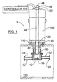
Fig. 1 illustrates a small-scale or micro-media mill according to one embodiment of the present invention.
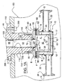
Fig. 1A illustrates an enlarged detailed view of the mill shown inFig. 1 .
Fig. 2 illustrates the media mill ofFig. 1 , but with a different vessel.
Fig. 3 illustrates a small-scale or micro-media mill according to another embodiment of the present invention.
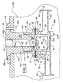
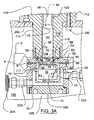
Fig. 3A illustrates an enlarged detailed view of the mill shown inFig. 3 .
Fig. 3B illustrates an enlarged detailed view taken alongarea 3B ofFig. 3A .
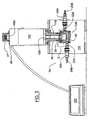
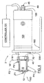
Fig. 4 illustrates a side view of a small scale or micro media mill according to another embodiment of the present invention.
Fig. 5 illustrates another embodiment of an agitator and another embodiment of a vessel that can be used with the media mill ofFigs. 1-4 .
Fig. 6 illustrates the agitator of the type illustrated in the embodiments ofFigs. 1-4 .
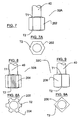
Fig. 7-13D illustrate various agitator configurations that can be used with the media mill ofFigs. 1-4 . - Although references are made below to directions in describing the structure, they are made relative to the drawings (as normally viewed) for convenience. The directions, such as top, bottom, upper, lower, etc., are not intended to be taken literally or limit the present invention.
- A small-
scale mill Figs. 1-4 ) according to the present invention is designed to mill relatively small amounts of dispersion to a size ranging from microns to nanometers in a relatively short time, i.e., a few hours or less, using attrition milling media, such as polymertype, e.g., cross linked polystyrene media, having nominal size no greater than about 500 microns (0.5 mm) to about 50 microns or mixtures of the sizes ranging between them. The performance of the present scale mill is designed to provide the results comparable to the DYNO-MILL and the NETZSCH ZETA mills. Themill - A vertically oriented
mills Figs. 1-3A . Themill vessel mixer 30, acoupling 50, and a rotatable journaledshaft 120, which can be that of amotor 100. Thevessel Figs. 5 and6 , or jacketed (double-walled) 10, 10A, 10B, as shown inFigs. 1-3A , to allow water cooling. Theagitator 30, which comprises arotor 32 and ashaft 40 extending from one end of therotor 32, is preferably a single piece to ease cleaning, and is adapted to be connected to a conventionalelectric motor 100, which preferably is capable of rotating up to 6000 RPM. A conventional motor controller 101 (Figs. 1 ,3 ,4 ), such as SERVO-DYNE Mixer Controller available from Cole-Farmer Instrument Co. of Vernon Hills, III, can control the motor speed and duration. Thecoupling 50 is mounted to themotor 100 and is coupled to thevessel 10 using a sanitary fitting and a clamp C (shown in phantom inFig. 3 ) to seal thevessel - Referring to
Fig. 1A , thevessel 10 in this embodiment is double walled or jacketed to circulate a coolant. Specifically, thevessel 10 comprises an innercylindrical wall 12 and an outercylindrical wall 14 spaced from and concentric with the innercylindrical wall 12. Theouter wall 14, however, need not be cylindrical or concentric relative to theinner wall 12. It can have any configuration that allows water circulation to the innercylindrical wall 12. An annular mountingflange 16 holds together top end of the inner and outercylindrical walls cylindrical wall 12 has abottom wall 13 enclosing its bottom end to form an inner vessel (12, 13). The outercylindrical wall 14 also has abottom wall 15 enclosing its bottom end and spaced from thebottom wall 13 to form an outer vessel (14, 15). The outer vessel (14, 15) is spaced from the inner vessel (12, 13) and forms a vessel shapedchamber 17 that can be filled with water and circulated to cool the dispersion during milling. - The outer
cylindrical wall 14 has twoopenings 20, preferably positioned diametrically opposite to each other and a pair ofcoolant connectors 22 aligned with theopenings 20. Either of theseconnectors 22 can serve as a coolant inlet or outlet. Theseconnectors 22 can extend substantially radially outwardly. The free end of each connector can have a sanitary fitting, which includes an annular mountingflange 24 and a complementary fitting (essentially mirror image thereof - not shown), adapted to be clamped with, for example, a TRI-CLAMP available from Tri-Clover Inc. of Kenosha, WI. These mountingflanges 24 are configured substantially similar to the mountingflanges vessel motor 100. All of these mountingflanges flanges annular gasket 60 and a beveled or tapered surface B. The mounting flanges and thegasket 60, which is FDA approved, adapted for the TRI-CLAMP are also available from Tri-Clover Inc. -
Fig. 2 shows another embodiment of the doublewalled vessel 10A, which is substantially similar to that shown inFigs. 1 and1A . The difference is that thebottom wall 13 of the innercylindrical wall 12 inFig. 2 is exposed. In other words, thealternative vessel 10A ofFig. 2 has no outerbottom wall 15 ofFig. 1A . Thealternative vessel 10A has itsbottom wall 13 extending radially outwardly to the outercylindrical wall 14. Thechamber 17 is annular instead of being vessel shaped (Fig. 2 ). Thebottom wall 13 can have a heat sink or a Peltier coolant (not shown) attached. Thebottom wall 13 also can have an observation window or anopening 205, which can be sealed or can have avalve 210 that vents excess pressure build up and/or allows a sample withdrawal. This way, minute amounts of dispersion can be taken out and examined without having to take off thecoupling 50. Alternatively, the opening can be sealed using a self-sealing resilient material that permits insertion of a syringe for withdrawing samples. Thewindow 205 can have a small chamber extending outwardly from the bottom (not shown). This chamber can hold a small amount of dispersion so that it can be viewed through an observation device. This chamber can be configured so that the dispersion is constantly circulated, such as placing thewindow 205 in a location where the dispersion is constantly moving. -
Figs. 3 and3A show another embodiment of the doublewalled vessel 10B, which is substantially similar to that shown inFigs. 1 and1A . The primary difference is that the outerbottom wall 15A can be threaded or screwed (or sealingly mounted) into the outercylindrical wall 14. In this respect, the outerbottom wall 15A can have an annular groove (not numbered) that seats an O-ring 74 or the like to provide a better water seal. Another difference from the vessel ofFigs. 1 and1A , is that a quick couple fitting 22A, 24A, 24B is used. Theconnectors 22A are threadlingly mounted to theopenings 20 formed in the outercylindrical wall 14. Theconnectors 22A can use a commercially available quick connector orcouple 24A, such as 1/8"PARKER series 60 Quick Couple. Thequick couple 24A can be connected to aflexible hose barb 24A, such as a commercially availablestainless steel 1/8" NPT x 1/4" hose barb. The double-walled vessels Figs. 1-2 . - Alternative to the double walled vessel is a single
walled vessel 10C shown inFigs. 5 and6 . The singlewalled vessel 10C can be used when the product to be milled is not heat sensitive or for milling a short period. The single walled vessel is constructed similarto the inner vessel (12, 13) of the doublewalled vessel 10. A heat sink (not shown) can be attached to itscylindrical wall 12 andbottom wall 13. The heat sink also can be fan cooled. Another alternative cooling system can be a Peltier cooler, which operates on the Peltier effect theory (cooling by flowing an electric current through a Peltier module made of two different types of conductive or semiconductive materials attached together). A Peltier module with a heat sink (Peltier coolant) can be detachably attached to the vessel. - In the embodiments of
Figs. 1-3 ,5 , and6 , the mountingflange 52 of thecoupling 50 is configured substantially the same as or complementary to the annular mountingflange 16. The mountingflanges gasket 60, such as a Tri-Clamp EPDM black, FDA approved gasket, sandwiched therebetween, as shown inFigs. 1A ,2 , and3A . Thegasket 60 has annular lower 62 and upper 64 protrusions that engage the respective grooves G formed in the mountingflanges flanges Fig. 3 ) can engage the periphery P and the beveled surfaces B of the mountingflanges flanges - The mounting
flanges 24 of the connectors 22 (Figs. 1 ,1A ,2 ) can be connected to their respective water source and drain pipes (not shown) in the same way as thevessel coupling 50, as just described, using agasket 60 and a TRI-CLAMP C. - Referring to the embodiments of
Figs. 1-3A , thecoupling 50 also has acylindrical portion 54 extending from its mountingflange 52. Theflange 52 has acentral opening 56 and a steppedrecess 58 concentric with theopening 56. Therecess 58 seats a seal, which can be a lip ormechanical seal ring 70 having a complementary configuration. Specifically, theseal ring 70 can be made from PTFE with a Wolastonite filler and can have an L-shaped (cross-sectional) profile as shown in detail inFig. 3B . Theseal ring 70 also can include a concentric O-ring 71 or the like, as shown inFig. 3B . Theopening 56 is dimensioned only slightly larger than the agitator'sshaft 40. Theseal ring 70 is adapted to engage theshaft 40 and seal the same while permitting theagitator 30 to rotate. - Referring to
Figs. 1A ,2 ,3A , thecylindrical portion 54 is threaded on its inner side so that it can be attached to themotor 100. Specifically, thecoupling 50 is attached to ashaft mount 110, which comprises anannular flange 112 and a downwardly extendingcylindrical member 114. Thecylindrical member 114 has an outer threading forthread-ingly mating with the threadedcylindrical portion 54 of thecoupling 50. Theflange 112 is mounted to themotor using bolts 200 or the like. Themotor 100 can be mounted to a stand orfixture 150 via theflange 112, usingbolts 200. Thestand 150 allows themotor 100 and thevessel Figs. 1 ,1A ,2 , and3 . - The
shaft mount 110 has a central throughhole 115 dimensioned larger than theshaft 40. The distal (lower) end of thecylindrical member 114 has anannular projection 116 that bears against the seal ring 70 (seeFig. 3B ) and holds theseal ring 70 in place. Thecoupling 50 has anannular end face 55 that abuts against a complementary face orshoulder 117 formed on the distal (lower) end of thecylindrical member 114, adjacent to theannular projection 116. Theend face 55 provides a positive stop and maintains proper seal compression when thecoupling 50 is mounted to theshaft mount 110. In this respect, referring toFig. 3A , the mountingflange 52 can also include an O-ring 72 positioned in anannular groove 59 formed on the upper end face 55 to provide additional seal. As the temperature of the dispersion increases during milling, expanding air under pressure is designed to escape through theseal ring 70, while maintaining liquid seal. In this respect, thecylindrical member 114 has avent opening 118 to vent any air seeping through theseal ring 70. - The
rotor shaft 40 comprises alarger diameter portion 42 and asmaller diameter portion 44 having a threadedfree end 45. A taperedsection 46 extends between theseportions rotor 30 is attached to themotor 100 by inserting thesmaller diameter portion 44 into ahollow motor shaft 120 and threading anut 49 or amanual knob 49A (Fig. 3 ) onto the threadedend 45, which tightly pulls the taperedsection 46 against the lower end or mouth of thehollow shaft 120, compressively attaching theagitator shaft 40 to thehollow motor shaft 120. Thenut 49 or theknob 49A can be covered with a safety cap 47 (Fig. 3 ), which can be mounted to the top end of themotor 100 using abase 48. The cap 47 can be threadedly mounted to thebase 48. The taperedsection 46 also eases the insertion of theshaft 40 through theseal ring 70 and prevents tear or damage to theseal ring 70. At least around a section CP of the largediametered shaft portion 42 contacting theseal 70 is preferably coated with a wear resistant coating, such as a hard chrome coating to prevent wear. - Although the above-described mill 1 (
Figs. 1-3B ) has been described and shown in a vertical configuration, the present invention also contemplates a horizontally oriented mill 2, as shown inFig. 4 . The horizontally oriented mill 2 is substantially similar to the vertically orientedmill 1 shown inFigs. 1-3 , except for the vessel and coupling configuration. In the horizontally oriented mill, a mountingbracket 160 is attached to themotor 100 via theshaft mount 110 so that the mill 2 is stably supported in the horizontal position, as shown inFig. 4 . In the horizontally oriented mill 2, itsvessel 10D can be attached to the motor via a threaded coupling 16', and theshaft 40 can be sealed via a single or double mechanical seal, or alip seal 70' (shown in phantom). - Referring to
Fig. 4 , thevessel 10D for the horizontally oriented mill 2 is substantially similar to the singledwalled vessel 10C (Fig. 5 and6 ), except that the flange 16 (Figs. 5 and6 ) has a threaded coupling 16', substantially similar to the threadedcoupling 50 shown inFigs. 1-3A . Thevessel 10D has an opencylindrical wall 12, with one closed by anend wall 13. The threaded coupling 16' is integrally or monolithically formed at the opposite open end. Thevessel 10D, however, can be configured like the singledwalled vessel 10C for use with the afore-described sanitary fitting. - The
vessel 10D is illustrated with four fill/drain/cooling ports P1-P4 for illustrative purposes only. Only one port is needed in the horizontally oriented mill 2. The ports P2-P4 are radially extending through thecylindrical wall 12 of thevessel 10B, whereas the port P1 is axially extending from theend wall 13 of thevessel 10B. In one embodiment, thevessel 10D can have a single top fill port P2 or P3. In such an embodiment, it is especially desirable for the top port P2 or P3 to be located at or along the highest point of the milling chamber, i.e., at 12 O'clock position for acylindrical vessel 10D, as this allows the chamber to be filled so that all of the air is displaced from the chamber. The absence of air in the milling chamber during operation prevents the formation of foam and enhances milling performance. - Alternatively, the horizontally oriented
vessel 10D can contain two or more ports, such as two top radial ports P2 and P3, a single axial port P1 and a single top radial port P3, or a single top radial port P3 and a single bottom radial port P4. In such embodiments, the dispersion can be externally circulated through thevessel 10D, where one port acts as an outlet and the other an inlet. The dispersion can be cooled or replenished during the circulating process. Using two ports, one can recirculate (or add) the process fluid and/or attrition media via an external vessel and pump (not shown). If the attrition media has to remain in the vessel, the outlet port can be fitted with a suitable screen or filter to retain the media during operation. - Referring to
Figs. 5-13D , therotor mills agitator 30 is preferably made of stainless steel or teflon or stainless steel with a teflon coating. In this respect, the TRI-CLAMP can be made of 304 stainless steel. The components that are exposed to the dispersion also can be made of 316 stainless steel. In fact, all of the metal components, except the clamp and the motor can be made of 316 stainless steel. Alternatively, all metal components that become exposed to the dispersion can be made of any material that is resistant to crevice corrosion, pitting, and stress corrosion, such as an AL-6XN stainless steel alloy. An AL-6XN alloy meets ASME and ASTM specifications, and is approved by the USDA for use as a food contact surface. - The
rotor 32 also can comprise a variety of geometries, surface textures, and surface modifications, such as channels or protrusions to alter the fluid flow patterns. For example, therotor 32 can be cylindrical (straight), as shown inFig. 5 , or cylindrical (tapered ends T1, T2) as shown inFigs. 1-4 and6 . In other illustrated embodiments, therotor 32 can be hexagonal (Fig. 7 ), ribbed (Fig. 8 ), square (Fig. 9 ), cylindrical with channels (Figs. 10 and 11 ), cylindrical with passageways (Fig. 12 ), and cylindrical with a cavity and slots (Figs. 13-13D ). All of these embodiments can have tapered end surfaces T1, T2. - Specifically, the
hexagonal rotor 32A (Fig. 7 ) has sixplanar sides 202. Theribbed rotor 32B (Fig. 8 ) hashexagonal sides 202 as shown inFig. 7 , but with sixribs 204 extending respectively from the middle of each of the sixsides 202. Thesquare rotor 32C (Fig. 9 ) has fourplanar sides 206. Thecylindrical rotor 32D (Fig. 10 ) has fourchannels 208 that are perpendicular to eachadjacent channels 208. Thecylindrical rotor 32E (Fig. 11 ) is substantially identical to thecylindrical rotor 32D ofFig. 10 , but has sixchannels 208 instead of four, symmetrically angled and spaced apart. Thecylindrical rotor 32F (Fig. 12 ) has fourangled passageways 210, extending from the tapered or conical end surfaces T1, T2. These angled passageways have four openings at the first tapered end surface T1 and four openings at the second tapered end surface T2. An imaginary circle intercepting the four openings at the first tapered end surface T1 has a greater diameter than an imaginary circle intercepting the four openings at the second tapered end surface T2. - The
cylindrical rotors Figs. 13-13D ) each have a concentricalcylindrical cavity 212 opening to the second tapered surface T2. Depending on the material and the media mill size, these rotors can have at least three (not shown) equally spaced apart axially extendingflow modifying channels 214. Therotors 32G-23J are respectively shown with four, six, eight, and ninechannels 214. Theseslots 214 can also be angled as shown, or spiraled or helically configured (not shown) relative to the rotational axis. In the embodiment ofFig. 13A , fourchannels 214 can be angled 90° relative to the adjacent channels. In the embodiment ofFig. 13B , the sixchannels 214 can be angled 60°. In the embodiment ofFig. 13C , the eightchannels 214 can be angled 45°. In the embodiment ofFig. 13D , the ninechannels 214 can be angled 40° relative to the vertical. In alternative embodiments (not shown), thechannels 214 can radially extend from the axis of the rotor 41. - The
rotors 32G-32J ofFigs. 13A-13D can act as a pump. That is, these rotors can withdraw fluid into thecavity 212 and eject fluid outwardly through thechannels 214, or conversely withdraw fluid into the cavity through thechannels 214 and eject fluid outwardly through thecavity 212, depending on the direction of the rotation, to modify the dispersion flow pattern. - In other embodiments (not shown), rotors also can contain pegs, agitator discs, or a combination thereof.
- Referring to the
cylindrical rotor 32 shown inFigs. 1-6 , its outer peripheralcylindrical surface 36 and the innercylindrical surface 12" of the innercylindrical wall 12 of thevessel U.S. Patent No. 5,718,388 issued to Czekai , et al. The largest attrition milling media preferably is nominally sized no greater than 500 microns (0.5 mm). Presently, the smallest attrition milling media contemplated is about 50 microns. Nonetheless, it is envisioned that a smaller attrition milling media can be suitable for milling certain non-soluble products, such as pharmaceutical products, which means that the gap X can be made smaller accordingly. - The vessel size can vary for milling small amounts of dispersion. The inner diameter of the vessel is between 5/8 inch to 4 inches. By way of examples only, milling chamber of the
vessel cylindrical rotor 32 can have the dimensions specified in Tables 1 and 2.TABLE 1 (STRAIGHT ROTORS) CYLINDRICAL VESSEL Size #1 #2 #3 TRI-CLAMP Size VESSEUCOUPLING 2" TC 2.5" TC 3" TC R-vessel (inch) (1/2 DC) 0.685 0.935 1.185 H-vessel (inch) (HC) 1.125 1.125 1.125 R-rotor (inch) (1/2 DR) 0.567 0.817 1.063 H-rotor (inch) (HR) 0.890 0.890 0.890 R-shaft (inch) (1/2 DS) 0.313 0.313 0.313 H-shaft (inch) (HS) 0.118 0.118 0.118 Volume Vessel (in3) 1.658 3.090 4.963 Volume Rotor (in3) 0.899 1.866 3.156 Volume Shaft (in3) 0.036 0.036 0.036 Working Volume (in3) 0.723 1.187 1.770 11.855 ml 19.458 ml 29.012 ml Typical Dispersion Volume @ 50% media charge 8.299 ml 13.621 ml 20.309 ml Typical Dispersion Volume @ 90% media charge 5.453 ml 8.951 ml 13.346 ml TABLE 2 (TAPERED ROTORS) VESSEL Size #1 #2 #3 TRI-CLAMP Size VESSEL/COUPLING 2" TC 2.5" TC 3" TC R-vessel (inch) (1/2 DC) 0.685 0.935 1.185 H-vessel (inch) (HC) 1.190 1.190 1.190 R-rotor (inch) (1/2 DR) 0.567 0.817 1.063 H-rotor (inch) (HR) 1.018 1.018 1.018 H-top taper (inch) (HTT) 0.064 0.120 0.120 H-bottom taper (inch) (HBT) 0.064 0.075 0.075 R-shaft (inch) (1/2 DS) 0.313 0.313 0.313 H-shaft (inch) (HS) 0.086 0.086 0.086 Volume Vessel (in3) 1.754 3.268 5.250 Volume Rotor Body (in3) 0.899 1.726 2.919 Volume Upper Cone (in3) 0.040 0.128 0.196 Volume Lower Cone (in3) 0.040 0.080 0.122 Volume Shaft (in3) 0.026 0.026 0.026 Volume Complete Rotor (in3) 0.979 1.934 3.237 Working Volume (in3) 0.749 1.308 1.986 12.274 ml 21.429 ml 32.548 ml Typical Dispersion Volume @ 50% media charge 8.592 ml 15.001 ml 22.784 ml Typical Dispersion Volume @ 90% media charge 5.646 ml 9.858 ml 14.972 ml - It was mentioned that the gap X between the
rotor 32 and theinner surface 12" of thecylindrical wall 12 should be approximately 6 times the diameter of the attrition milling media. Nonetheless, the vessel and rotor combination can be used with 50, 200, 500 and mixtures of 50/200,50/500, or 50/200/500 micron media. These milling media also can be used with a gap X of 1 mm. The rotor speed is correlated to the rotor diameter to produce different tip speeds, which are related to the milling action. A too high tip speed can generate much heat and can evaporate the dispersion. A too low tip speed causes inefficient milling. - Tapering the ends of the
rotor 32, as illustrated inFigs. 1-4 and6-13D can provide more uniform shear throughout the milling chamber. Although the shear rate between two concentric cylinders is relatively constant if the gap is narrow, a flat end (bottom or top) surface cylinder will produce less uniform shear stress. Referring toFig. 6 , by equating the shear rate for concentric cylinders and a cone shape surface T2 revolving about a flat bottomedvessel surface 13", one can calculate a tip angle β = arc tan (1 - DR/DC), where DR represents an outercylindrical surface 36 of therotor 32 and DC represents an innercylindrical surface 12" of thevessel bottom vessel surface 13". The gap d is preferably defined by DT/2 × tanβ, where DT/2 is the distance between the center of rotation and the truncation edge. If DT/2 is sufficiently small in comparison with DR/2, a substantially uniform shear can be maintained. A uniform shear rate would allow the user to better estimate shearing effect in the milling of colloidal dispersions, although constant shear in the mill is not necessary to produce a colloidal dispersion. Another benefit to having a tapered bottom surface T2 is that it prevents the accumulation of suspended particles on the bottom near the center of rotation where the speed is at its minimal. -
U.S. Patent Nos. 5,4145,786 5,518,187 issued to Bruno , et al., and5,718,388 and5862,999 issued to Czekai , et al. disclose milling pharmaceutical products using polymeric milling media. These patents further disclose dispersion formulations for a wet media milling. The disclosures of these patents are incorporated herein by reference. - In operation of the vertically oriented
mill vessel Figs. 5 and6 ) of the gasket 60 (or even overflow) when therotor 30 fully inserted to thevessel 10 to minimize trapping of air within the vessel. After filling appropriate amount of the dispersion into thevessel coupling 50, which is premounted to theshaft mount 110, and raised until the vessel andcoupling flanges coupling flanges vessel coupling 50 and seals the dispersion. Similarly, theconnectors quick coupling 24A, one for eachconnector vessel motor controller 101 can be set to rotate the rotor for a predetermined period, depending on the dispersion formulation. - Because the
coupling 50 seals thevessel rotor 32 can be spun faster. Thus, a higher energy can be transferred to the dispersion.. - In the operation of the horizontally oriented mill 2, the
vessel 10D is first mounted to theshaft mount 110 with either a threaded coupling 16' (as shown inFig. 4 ) or a sanitary fitting (as shown inFigs. 1-3 ) and with therotor 32 positioned inside thevessel 10D as shown inFig. 4 . The dispersion formulation containing the milling media and the product to be milled is poured or injected through the top port P2 or P3 (only one being required) until all or substantially all of the air is displaced with the dispersion. Themotor controller 101 then can be set to rotate therotor 32 for a predetermined period, depending on the dispersion formulation. If thevessel 10D has multiple ports, such as P1, P3 or P2, P3, or P3, P4, the dispersion can be circulated via an external vessel and pump (not shown) during milling. - Because virtually all or substantially all of the air can be displaced in the horizontally oriented mill 2, vortexing and contamination problems are minimized or avoided. Thus, the mill according to the present invention can prevent the dispersion formulation from foaming. Further, because the dispersion can be circulated, where it can be cooled with external cooling system, the rotor can be spun faster and high energy can be transferred to the dispersion. Moreover, the dispersion can be refreshed or made in batches or inspected without having to disassemble the
vessel 10D from theshaft mount 110. - The pharmaceutical products herein include those products described in the aforementioned patents incorporated herein by reference and any human or animal ingestable products and cosmetic products.
- Given the disclosure of the present invention, one versed in the art would appreciate that there may be other embodiments and modifications within the scope and spirit of the present invention. Accordingly, all modifications attainable by one versed in the art from the present disclosure within the scope and spirit of the present invention are to be included as further embodiments of the present invention. The scope of the present invention accordingly is to be defined as set forth in the appended claims.
Claims (82)
- A small-scale mill for milling a pharmaceutical product, comprising:(a) a shaft mount (110);(b) a rotatable shaft (120) mounted for rotation about the shaft mount (110);(c) a vessel (10) having an opening;(d) an agitator (30) having a rotor (32) and a rotor shaft (40) extending from the rotor (32), the shaft (40) being connected to the rotatable shaft (120) and the rotor (32) being dimensioned to be inserted in the vessel (10) with a small gap formed between an outer rotating surface of the rotor (32) and an internal surface of the vessel (10);(e) a coupling (50) detachably connecting the vessel to the shaft mount, the coupling having an opening (56) through which the rotor shaft extends, wherein the product is in a liquid dispersion containing attrition milling mediacharacterized in that
the vessel (10) has a volume of 86 ml or less,
the shaft mount seals the vessel opening to seal the dispersion in the vessel,
the coupling (50) comprises a seal (70) which seals the shaft (40),
wherein the shaft mount and the coupling are adapted to hold the seal such that when the coupling is mounted to the shaft mount, expanding air can escape through the seal while maintaining a liquid seal. - A small-scale mill according to claim 1, further including a cooling system connected to the vessel.
- A small scale mill according to claim 2, wherein the vessel comprises a cylindrical inner vessel (12) and an outer vessel (14) spaced from and surrounding the inner vessel and forming a chamber (17) therebetween, and a flange (24) connecting the ends thereof, the outer vessel having at least first and second passages (20) that communicate with the chamber (17), the cooling system comprising the outer vessel with the first and second passages (20), which is adapted to circulate cooling fluid.
- A small-scale mill according to claim 2, wherein the cooling system comprises a plurality of ports on the vessel for circulating the dispersion.
- A small-scale mill according to claim 1, wherein the vessel is vertically oriented.
- A small-scale mill according to claim 1, wherein the vessel is horizontally oriented.
- A small-scale mill according to claim 1, wherein the coupling (50) has a threaded portion for detachably mounting to the shaft mount and a flange portion for detachably coupling to the vessel.
- A small-scale mill according to claim 1, wherein the coupling (50) is integrally formed with the vessel and has a threaded portion (54) for detachably mounting to the shaft mount (110).
- A small-scale mill according to claim 1, wherein the vessel includes at least one port through which the dispersion is filled.
- A small-scale mill according to claim 1, wherein the vessel includes at least two ports through which the dispersion is circulated.
- A small-scale mill according to claim 1, wherein the shaft (120) is a motor shaft of a motor (100), wherein the motor is a variable speed motor and has a top speed of 6000 RPM.
- A small-scale mill of claim 1, wherein the ratio of the distance between the outer periphery of the rotor (32) and the inner surface of the vessel (10) to the nominal size of the attrition milling media is about 6 to 1.
- A small-scale mill according to claim 1, wherein the rotor (32) is cylindrical and the vessel is cylindrical, the small gap being no larger than 3 mm.
- A small-scale mill according to claim 13, wherein the rotor (32) is cylindrical, the vessel (10) is cylindrical, and the small gap is no larger than 1 mm.
- A small-scale mill according to claim 13, wherein the cylindrical rotor (32) has tapered end surfaces.
- A small-scale mill according to claim 15, wherein the cylindrical rotor (32) has a cavity and a plurality of slots that extend between an inner surface of the cavity and an outer surface of the cylindrical rotor.
- A small-scale mill according to claim 15, wherein the cylindrical rotor (32) has a plurality of channels extending to an outer surface of the cylindrical rotor.
- A small-scale mill according to claim 15, wherein the cylindrical rotor has a plurality of passageways extending between the tapered end surfaces of the cylindrical rotor.
- A small-scale mill of claim 1, wherein during milling substantially uniform shear is maintained throughout the milling chamber.
- A small-scale mill of claim 1, wherein the attrition media is selected from the group consisting of polymeric media, polystyrene media, and cross-linked polystyrene media.
- A small-scale mill of claim 20, wherein the attrition media is polymeric.
- A small-scale mill according to claim 1, wherein the attrition media has a nominal size of no larger than about 500 microns.
- A small-scale mill according to claim 1, wherein the attrition media has a nominal size no larger than about 200 microns.
- A small-scale mill according to claim 1, wherein the attrition media has a nominal size of about 50 microns or greater.
- A small-scale mill according to claim 1, wherein the attrition media comprises nominal sizes selected from the group consisting of about 50 microns, about 200 microns, about 500 microns, and a mixture thereof.
- A small-scale mill according to claim 1, wherein the attrition media comprises nominal sizes selected from the group consisting of about 50 microns or greater, about 200 microns or greater, no greater than about 500 microns, and a mixture thereof.
- A small-scale mill of claim 1, wherein the pharmaceutical product is a heat sensitive product.
- A small-scale mill of claim 1, wherein the pharmaceutical product is a human or animal ingestable product.
- A small-scale mill of claim 1, wherein the pharmaceutical product is a cosmetic product.
- A small-scale mill of claim 1, wherein at the completion of milling, the product has a particle size in the range of microns to nanometers.
- A small-scale mill of claim 1, wherein the working volume of the mill is about 11.8 ml to about 32.5 ml.
- A small-scale mill of claim 31, wherein the working volume of the mill is about 11.8 ml to about 29 ml.
- A small-scale mill of claim 32, wherein the working volume of the mill is about 11.8 ml to about 21.4 ml.
- A small-scale mill of claim 33, wherein the working volume of the mill is about 11.8 ml to about 19.5 ml.
- A small-scale mill of claim 34, wherein the working volume of the mill is about 11.8 ml to about 12.3 ml.
- A small-scale mill of claim 1, wherein at a 50% attrition media load, the dispersion volume is about 8.3 ml to about 22.8 ml.
- A small-scale mill of claim 36, wherein at a 50% attrition media load, the dispersion volume is about 8.3 ml to about 20.3 ml.
- A small-scale mill of claim 37, wherein at a 50% attrition media load, the dispersion volume is about 8.3 ml to about 15.0 ml.
- A small-scale mill of claim 38, wherein at a 50% attrition media load, the dispersion volume is about 8.3 ml to about 13.6 ml.
- A small-scale mill of claim 1, wherein at a 90% attrition media load, the dispersion volume is about 5.4 ml to about 15.0 ml.
- A small-scale mill of claim 40, wherein at a 90% attrition media load, the dispersion volume is about 5.4 ml to about 13.3 ml.
- A small-scale mill of claim 41, wherein at a 90% attrition media load, the dispersion volume is about 5.4 ml to about 9.8 ml.
- A small-scale mill of claim 42, wherein at a 90% attrition media load, the dispersion volume is about 5.4 ml to about 8.9 ml.
- A method of milling a pharmaceutical product, comprising:(a) providing a liquid dispersion comprising the product to be milled and attrition milling media having a nominal size of no greater than about 500 microns;(b) inserting the dispersion into a cylindrical vessel having a volume of 86 ml or less;(c) providing an agitator and a coupling that closes the vessel, the coupling having an opening through which a portion of the agitator extends and the agitator comprising a cylindrical rotor and a shaft extending therefrom, wherein the cylindrical rotor is dimensioned so that a gap of no greater than 3 mm is formed between an outer rotating surface of the rotor and an internal surface of the vessel;(d) inserting an agitator into the cylindrical vessel and sealingly closing the coupling such that expanding air can escape while maintaining a liquid seal, wherein the vessel is filled so that the dispersion eliminates substantially all of the air in the vessel when the agitator is fully inserted into the vessel; and(e) rotating the agitator for a predetermined period.
- A method according to claim 44, further including cooling the vessel.
- A method according to claim 45, wherein the vessel is cooled by jacketing the vessel and flowing water between the jacket and the vessel.
- A method of claim 44, wherein the attrition media is selected from the group consisting of polymeric media, polystyrene media, or cross-linked polystyrene media.
- A method of claim 44, wherein the attrition media is polymeric
- A method of claim 44, wherein the attrition media has a nominal size of no larger than about 500 microns.
- A method of claim 44, wherein the attrition media has a nominal size no larger than about 200 microns.
- A method of claim 44, wherein the attrition media has a nominal size of about 50 microns or greater.
- A method of claim 44, wherein the attrition media comprises nominal sizes selected from the group consisting of about 50 microns, about 200 microns, about 500 microns, and a mixture thereof.
- A method of claim 44, wherein the attrition media comprises nominal sizes selected from the group consisting of about 50 microns or greater, about 200 microns or greater, no greater than about 500 microns, and a mixture thereof.
- A method of claim 44, wherein the pharmaceutical product is a heat sensitive product.
- A method of claim 44, wherein the pharmaceutical product is a human or animal ingestable product.
- A method of claim 44, wherein the pharmaceutical product is a cosmetic product.
- A method of claim 44, wherein the ratio of the distance between the outer periphery of the cylindrical rotor and the inner surface of the vessel to the attrition milling media nominal size is about 6 to 1.
- A method of claim 44, further comprising maintaining substantially uniform shear throughout the milling chamber.
- A method of claim 44, wherein at the completion of milling, the product has a particle size in the range of microns to nanometers.
- A method of claim 44, wherein the vessel is vertically oriented.
- A method of claim 44, wherein the vessel is horizontally oriented.
- A method of claim 44, further including externally circulating the dispersion.
- A method of claim 44, wherein the dispersion is retained in the vessel during rotation of the agitator.
- A method of claim 44, wherein the dispersion is recirculated through the vessel during rotation of the agitator.
- A method of claim 44, wherein the predetermined period of rotation of the agitator is a few hours or less.
- A method of claim 44, further comprising minimizing vortexing during rotation of the agitator.
- A method of claim 44, further comprising preventing the dispersion from foaming.
- A method of claim 44, further comprising minimizing or avoiding contamination of the dispersion.
- A method of claim 44, wherein the working volume of the vessel is about 11.8 ml.
- A method of claim 44, wherein the working volume of the mill is about 11.8 ml to about 32.5 ml.
- A method of claim 70, wherein the working volume of the mill is about 11.8 ml to about 29 ml.
- A method of claim 71, wherein the working volume of the mill is about 11.8 ml to about 21.4 ml.
- A method of claim 72, wherein the working volume of the mill is about 11.8 ml to about 19.5 ml.
- A method of claim 73, wherein the working volume of the mill is about 11.8 ml to about 12.3 ml.
- A method of claim 44, wherein at a 50% attrition media load, the dispersion volume is about 8.3 ml to about 22.8 ml.
- A method of claim 75, wherein at a 50% attrition media load, the dispersion volume is about 8.3 ml to about 20.3 ml.
- A method of claim 76, wherein at a 50% attrition media load, the dispersion volume is about 8.3 ml to about 15.0 ml.
- A method of claim 77, wherein at a 50% attrition media load, the dispersion volume is about 8.3 ml to about 13.6 ml.
- A method of claim 44, wherein at a 90% attrition media load, the dispersion volume is about 5.4 ml to about 15.0 ml.
- A method of claim 79, wherein at a 90% attrition media load, the dispersion volume is about 5.4 ml to about 13.3 ml.
- A method of claim 80, wherein at a 90% attrition media load, the dispersion volume is about 5.4 ml to about 9.8 ml.
- A method of claim 81, wherein at a 90% attrition media load, the dispersion volume is about 5.4 ml to about 8.9 ml.
Applications Claiming Priority (3)
| Application Number | Priority Date | Filing Date | Title |
|---|---|---|---|
| US13714299P | 1999-06-01 | 1999-06-01 | |
| US137142P | 1999-06-01 | ||
| PCT/US2000/014705 WO2000072973A1 (en) | 1999-06-01 | 2000-05-31 | Small-scale mill and method thereof |
Publications (3)
| Publication Number | Publication Date |
|---|---|
| EP1185371A1 EP1185371A1 (en) | 2002-03-13 |
| EP1185371B1 EP1185371B1 (en) | 2004-07-28 |
| EP1185371B2 true EP1185371B2 (en) | 2008-11-12 |
Family
ID=22476002
Family Applications (1)
| Application Number | Title | Priority Date | Filing Date |
|---|---|---|---|
| EP00937882A Expired - Lifetime EP1185371B2 (en) | 1999-06-01 | 2000-05-31 | Small-scale mill and method thereof |
Country Status (8)
| Country | Link |
|---|---|
| US (3) | US6431478B1 (en) |
| EP (1) | EP1185371B2 (en) |
| JP (1) | JP4156807B2 (en) |
| AT (1) | ATE271922T1 (en) |
| AU (1) | AU5300000A (en) |
| CA (1) | CA2393195C (en) |
| DE (1) | DE60012520T3 (en) |
| WO (1) | WO2000072973A1 (en) |
Families Citing this family (114)
| Publication number | Priority date | Publication date | Assignee | Title |
|---|---|---|---|---|
| US20050004049A1 (en) * | 1997-03-11 | 2005-01-06 | Elan Pharma International Limited | Novel griseofulvin compositions |
| US20080213378A1 (en) * | 1998-10-01 | 2008-09-04 | Elan Pharma International, Ltd. | Nanoparticulate statin formulations and novel statin combinations |
| US8236352B2 (en) | 1998-10-01 | 2012-08-07 | Alkermes Pharma Ireland Limited | Glipizide compositions |
| US20090297602A1 (en) * | 1998-11-02 | 2009-12-03 | Devane John G | Modified Release Loxoprofen Compositions |
| US20080113025A1 (en) * | 1998-11-02 | 2008-05-15 | Elan Pharma International Limited | Compositions comprising nanoparticulate naproxen and controlled release hydrocodone |
| US20080102121A1 (en) * | 1998-11-02 | 2008-05-01 | Elan Pharma International Limited | Compositions comprising nanoparticulate meloxicam and controlled release hydrocodone |
| DK1126826T6 (en) | 1998-11-02 | 2019-06-24 | Alkermes Pharma Ireland Ltd | Multiparticulate modified release of methylphenidate |
| WO2001085344A1 (en) * | 2000-04-26 | 2001-11-15 | Elan Pharma International, Ltd. | Apparatus for sanitary wet milling |
| CN1321628C (en) * | 2000-06-28 | 2007-06-20 | 史密斯克莱·比奇曼公司 | Wet milling process |
| US7276249B2 (en) * | 2002-05-24 | 2007-10-02 | Elan Pharma International, Ltd. | Nanoparticulate fibrate formulations |
| US20080241070A1 (en) * | 2000-09-21 | 2008-10-02 | Elan Pharma International Ltd. | Fenofibrate dosage forms |
| US7998507B2 (en) * | 2000-09-21 | 2011-08-16 | Elan Pharma International Ltd. | Nanoparticulate compositions of mitogen-activated protein (MAP) kinase inhibitors |
| US20030224058A1 (en) * | 2002-05-24 | 2003-12-04 | Elan Pharma International, Ltd. | Nanoparticulate fibrate formulations |
| US6976647B2 (en) * | 2001-06-05 | 2005-12-20 | Elan Pharma International, Limited | System and method for milling materials |
| JP2005504266A (en) * | 2001-06-22 | 2005-02-10 | エラン ファーマ インターナショナル,リミティド | High-throughput screening methods using small-scale mills or microfluidics |
| JP2005519657A (en) * | 2001-11-07 | 2005-07-07 | インコール ファーマシューティカル カンパニー | Method of blood vessel imaging using nanoparticulate contrast agent |
| CA2475092C (en) | 2002-02-04 | 2012-05-01 | Christian F. Wertz | Nanoparticulate compositions having lysozyme as a surface stabilizer |
| US20040101566A1 (en) * | 2002-02-04 | 2004-05-27 | Elan Pharma International Limited | Novel benzoyl peroxide compositions |
| US20030215502A1 (en) * | 2002-03-20 | 2003-11-20 | Elan Pharma International Limited | Fast dissolving dosage forms having reduced friability |
| US20040076586A1 (en) * | 2002-03-28 | 2004-04-22 | Reinhard Koening | Compositions and methods for delivering pharmaceutically active agents using nanoparticulates |
| US20040105889A1 (en) * | 2002-12-03 | 2004-06-03 | Elan Pharma International Limited | Low viscosity liquid dosage forms |
| ES2380318T3 (en) | 2002-04-12 | 2012-05-10 | Alkermes Pharma Ireland Limited | Megestrol nanoparticular formulations |
| US7101576B2 (en) | 2002-04-12 | 2006-09-05 | Elan Pharma International Limited | Nanoparticulate megestrol formulations |
| US20100226989A1 (en) * | 2002-04-12 | 2010-09-09 | Elan Pharma International, Limited | Nanoparticulate megestrol formulations |
| US9101540B2 (en) * | 2002-04-12 | 2015-08-11 | Alkermes Pharma Ireland Limited | Nanoparticulate megestrol formulations |
| US20070264348A1 (en) * | 2002-05-24 | 2007-11-15 | Elan Pharma International, Ltd. | Nanoparticulate fibrate formulations |
| AU2003241477A1 (en) * | 2002-06-10 | 2003-12-22 | Elan Pharma International, Ltd. | Nanoparticulate polycosanol formulations and novel polycosanol combinations |
| US20040258757A1 (en) * | 2002-07-16 | 2004-12-23 | Elan Pharma International, Ltd. | Liquid dosage compositions of stable nanoparticulate active agents |
| US7407955B2 (en) | 2002-08-21 | 2008-08-05 | Boehringer Ingelheim Pharma Gmbh & Co., Kg | 8-[3-amino-piperidin-1-yl]-xanthines, the preparation thereof and their use as pharmaceutical compositions |
| ATE487470T1 (en) * | 2002-09-11 | 2010-11-15 | Elan Pharma Int Ltd | GEL-STABILIZED ACTIVE COMPOSITIONS IN NANOPARTICLE SIZE |
| WO2004032980A1 (en) * | 2002-10-04 | 2004-04-22 | Elan Pharma International Limited | Gamma irradiation of solid nanoparticulate active agents |
| CN1713893A (en) * | 2002-11-18 | 2005-12-28 | 纳幕尔杜邦公司 | Media milling using nonspherical grinding media |
| US20040173696A1 (en) * | 2002-12-17 | 2004-09-09 | Elan Pharma International Ltd. | Milling microgram quantities of nanoparticulate candidate compounds |
| CA2513064C (en) * | 2003-01-31 | 2009-11-10 | Elan Pharma International, Ltd. | Nanoparticulate topiramate formulations |
| US20040208833A1 (en) * | 2003-02-04 | 2004-10-21 | Elan Pharma International Ltd. | Novel fluticasone formulations |
| US20100297252A1 (en) | 2003-03-03 | 2010-11-25 | Elan Pharma International Ltd. | Nanoparticulate meloxicam formulations |
| US8512727B2 (en) | 2003-03-03 | 2013-08-20 | Alkermes Pharma Ireland Limited | Nanoparticulate meloxicam formulations |
| JP2007501683A (en) * | 2003-05-22 | 2007-02-01 | エラン ファーマ インターナショナル リミテッド | Sterilization of nanoparticle active substance dispersions by gamma irradiation |
| ITMI20031037A1 (en) * | 2003-05-23 | 2004-11-24 | Gamma Croma Spa | METHOD AND EQUIPMENT FOR THE MOLDING OF A COSMETIC PRODUCT. |
| DE10335552B4 (en) * | 2003-08-02 | 2005-07-28 | Stephan Machinery Gmbh & Co. | Mixing shaft for mixing and dividing food products and method for producing a coating for such a mixing shaft |
| ES2318330T3 (en) * | 2003-08-08 | 2009-05-01 | Elan Pharma International Limited | NEW COMPOSITIONS OF METAXALONA. |
| ES2366646T3 (en) * | 2003-11-05 | 2011-10-24 | Elan Pharma International Limited | COMPOSITIONS IN THE FORM OF NANOPARTICLES THAT HAVE A PEPTIDE AS A SURFACE STABILIZER. |
| EA200701065A1 (en) * | 2004-11-16 | 2007-12-28 | Элан Фарма Интернэшнл Лтд. | INJECTABLE COMPOSITIONS CONTAINING NANODISPERS Olanzapine |
| UA89513C2 (en) * | 2004-12-03 | 2010-02-10 | Элан Фарма Интернешнл Лтд. | Nanoparticulate raloxifene hydrochloride composition |
| JP2008524239A (en) * | 2004-12-15 | 2008-07-10 | エラン ファーマ インターナショナル リミティド | Nanoparticulate tacrolimus formulation |
| US20060159767A1 (en) * | 2004-12-22 | 2006-07-20 | Elan Pharma International Limited | Nanoparticulate bicalutamide formulations |
| EP1835890A2 (en) * | 2005-01-06 | 2007-09-26 | Elan Pharma International Limited | Nanoparticulate candesartan formulations |
| AU2006214443C1 (en) * | 2005-02-15 | 2011-11-24 | Alkermes Pharma Ireland Limited | Aerosol and injectable formulations of nanoparticulate benzodiazepine |
| US20080254114A1 (en) * | 2005-03-03 | 2008-10-16 | Elan Corporation Plc | Controlled Release Compositions Comprising Heterocyclic Amide Derivative Nanoparticles |
| WO2006099121A2 (en) * | 2005-03-10 | 2006-09-21 | Elan Pharma International Limited | Formulations of a nanoparticulate finasteride, dutasteride and tamsulosin hydrochloride, and mixtures thereof |
| CA2601179A1 (en) * | 2005-03-16 | 2006-09-21 | Elan Pharma International Limited | Nanoparticulate leukotriene receptor antagonist/corticosteroid formulations |
| JP2008533173A (en) * | 2005-03-17 | 2008-08-21 | エラン ファーマ インターナショナル リミテッド | Nanoparticulate bisphosphonate composition |
| KR20070121786A (en) * | 2005-03-23 | 2007-12-27 | 엘란 파마 인터내셔널 리미티드 | Nanoparticulate corticosteroid and antihistamine formulations |
| US20060246141A1 (en) * | 2005-04-12 | 2006-11-02 | Elan Pharma International, Limited | Nanoparticulate lipase inhibitor formulations |
| CN101171000A (en) * | 2005-04-12 | 2008-04-30 | 依兰药物国际有限公司 | Nanoparticulate and controlled release compositions comprising cyclosporine |
| BRPI0607537A2 (en) * | 2005-04-12 | 2009-09-15 | Elan Pharma Int Ltd | nanoparticulate quinazoline derivative formulations |
| US20070029252A1 (en) * | 2005-04-12 | 2007-02-08 | Dunson James B Jr | System and process for biomass treatment |
| JP5804666B2 (en) * | 2005-04-12 | 2015-11-04 | イー・アイ・デュポン・ドウ・ヌムール・アンド・カンパニーE.I.Du Pont De Nemours And Company | Concentration of separate supply streams in biomass processing and utilization |
| WO2006132752A1 (en) * | 2005-05-10 | 2006-12-14 | Elan Pharma International Limited | Nanoparticulate and controlled release compositions comprising vitamin k2 |
| MX2007014163A (en) * | 2005-05-10 | 2008-01-24 | Elan Pharma Int Ltd | Nanoparticulate clopidogrel formulations. |
| US20100028439A1 (en) * | 2005-05-23 | 2010-02-04 | Elan Pharma International Limited | Nanoparticulate stabilized anti-hypertensive compositions |
| WO2006133045A1 (en) * | 2005-06-03 | 2006-12-14 | Elan Pharma International, Limited | Nanoparticulate benidipine compositions |
| BRPI0613540A2 (en) | 2005-06-03 | 2011-01-18 | Elan Pharma Int Ltd | nanoparticulate imatinib mesylate formulations |
| EP1901728A2 (en) * | 2005-06-03 | 2008-03-26 | Elan Pharma International Limited | Nanoparticulate acetaminophen formulations |
| JP2009517485A (en) | 2005-06-08 | 2009-04-30 | エラン・ファルマ・インターナショナル・リミテッド | Nanoparticulate and controlled release compositions containing cefditoren |
| WO2006135689A2 (en) * | 2005-06-09 | 2006-12-21 | Elan Pharma International, Limited | Nanoparticulate ebastine formulations |
| CA2611741A1 (en) * | 2005-06-13 | 2006-12-28 | Elan Pharma International, Limited | Nanoparticulate clopidogrel and aspirin combination formulations |
| CA2612384A1 (en) * | 2005-06-15 | 2006-12-28 | Elan Pharma International, Limited | Nanoparticulate azelnidipine formulations |
| WO2007008537A2 (en) * | 2005-07-07 | 2007-01-18 | Elan Pharma International, Limited | Nanoparticulate clarithromycin formulations |
| JP2009507925A (en) * | 2005-09-13 | 2009-02-26 | エラン ファーマ インターナショナル リミテッド | Nanoparticle tadalafil formulation |
| JP2009508859A (en) * | 2005-09-15 | 2009-03-05 | エラン ファーマ インターナショナル リミテッド | Nanoparticulate aripiprazole formulation |
| CN103265495B (en) | 2005-12-29 | 2016-11-16 | 莱西肯医药有限公司 | Multicyclic amino acid derivatives and using method thereof |
| US7649098B2 (en) | 2006-02-24 | 2010-01-19 | Lexicon Pharmaceuticals, Inc. | Imidazole-based compounds, compositions comprising them and methods of their use |
| US8367112B2 (en) * | 2006-02-28 | 2013-02-05 | Alkermes Pharma Ireland Limited | Nanoparticulate carverdilol formulations |
| EP1852108A1 (en) | 2006-05-04 | 2007-11-07 | Boehringer Ingelheim Pharma GmbH & Co.KG | DPP IV inhibitor formulations |
| PE20080251A1 (en) | 2006-05-04 | 2008-04-25 | Boehringer Ingelheim Int | USES OF DPP IV INHIBITORS |
| MX2008014024A (en) | 2006-05-04 | 2008-11-14 | Boehringer Ingelheim Int | Polymorphs. |
| MX2008015275A (en) | 2006-05-30 | 2009-02-06 | Elan Pharma Int Ltd | Nanoparticulate posaconazole formulations. |
| WO2008008733A2 (en) * | 2006-07-10 | 2008-01-17 | Elan Pharma International Ltd. | Nanoparticulate sorafenib formulations |
| KR20090031618A (en) * | 2006-07-12 | 2009-03-26 | 엘란 코포레이션, 피엘씨 | Nanoparticulate formulations of modafinil |
| TWI318894B (en) * | 2006-08-07 | 2010-01-01 | Ind Tech Res Inst | System for fabricating nano particles |
| UA99270C2 (en) | 2006-12-12 | 2012-08-10 | Лексикон Фармасьютикалз, Инк. | 4-phenyl-6-(2,2,2-trifluoro-1-phenylethoxy)pyrimidine-based compounds and methods of their use |
| US20080259722A1 (en) * | 2007-04-23 | 2008-10-23 | Sanford Samuel A | Blender for production of scented materials |
| US7441717B1 (en) * | 2007-10-31 | 2008-10-28 | Eastman Kodak Company | Micromedia milling process |
| WO2009117401A2 (en) * | 2008-03-21 | 2009-09-24 | Elan Pharama International Limited | Compositions for site-specific delivery of imatinib and methods of use |
| PE20091730A1 (en) | 2008-04-03 | 2009-12-10 | Boehringer Ingelheim Int | FORMULATIONS INVOLVING A DPP4 INHIBITOR |
| BRPI0916997A2 (en) | 2008-08-06 | 2020-12-15 | Boehringer Ingelheim International Gmbh | DPP-4 INHIBITOR AND ITS USE |
| US20200155558A1 (en) | 2018-11-20 | 2020-05-21 | Boehringer Ingelheim International Gmbh | Treatment for diabetes in patients with insufficient glycemic control despite therapy with an oral antidiabetic drug |
| EP2371880B1 (en) * | 2008-12-26 | 2014-10-01 | Asahi Glass Company, Limited | Ethylene/tetrafluoroethylene copolymer granulation method |
| WO2010099508A1 (en) | 2009-02-26 | 2010-09-02 | Theraquest Biosciences, Inc. | Extended release oral pharmaceutical compositions of 3-hydroxy-n-methylmorphinan and method of use |
| DE202009006458U1 (en) | 2009-05-06 | 2010-09-23 | Hosokawa Alpine Ag | Housing for process engineering machines and apparatus |
| DE102009019869B4 (en) * | 2009-05-06 | 2012-09-06 | Hosokawa Alpine Ag | Housing for process engineering machines and apparatus |
| DE102009019868B4 (en) * | 2009-05-06 | 2015-10-22 | Hosokawa Alpine Ag | Process engineering plant for laboratory use |
| AU2010254180B2 (en) | 2009-05-27 | 2015-08-27 | Alkermes Pharma Ireland Limited | Reduction of flake-like aggregation in nanoparticulate active agent compositions |
| FR2945950A1 (en) | 2009-05-27 | 2010-12-03 | Elan Pharma Int Ltd | ANTICANCER NANOPARTICLE COMPOSITIONS AND METHODS FOR PREPARING THE SAME |
| AU2010315190A1 (en) | 2009-11-05 | 2012-05-10 | Lexicon Pharmaceuticals, Inc. | Tryptophan hydroxylase inhibitors for the treatment of cancer |
| EP3646859A1 (en) | 2009-11-27 | 2020-05-06 | Boehringer Ingelheim International GmbH | Treatment of genotyped diabetic patients with dpp-iv inhibitors such as linagliptin |
| AU2011215963A1 (en) | 2010-02-10 | 2012-08-02 | Lexicon Pharmaceuticals, Inc. | Tryptophan hydroxylase inhibitors for the treatment of metastatic bone disease |
| AU2011249722B2 (en) | 2010-05-05 | 2015-09-17 | Boehringer Ingelheim International Gmbh | Combination therapy |
| WO2011146583A2 (en) | 2010-05-19 | 2011-11-24 | Elan Pharma International Limited | Nanoparticulate cinacalcet formulations |
| US9034883B2 (en) | 2010-11-15 | 2015-05-19 | Boehringer Ingelheim International Gmbh | Vasoprotective and cardioprotective antidiabetic therapy |
| US10717960B2 (en) | 2011-10-10 | 2020-07-21 | Dasgip Information And Technology Gmbh | Biotechnological apparatus comprising a bioreactor, exhaust gas temperature control device for a bioreactor and a method for treating an exhaust gas stream in a biotechnological apparatus |
| WO2013148978A1 (en) | 2012-03-30 | 2013-10-03 | Lexicon Pharmaceuticals, Inc. | Methods and compositions for the treatment of necrotizing enterocolitis |
| EP3685839A1 (en) | 2012-05-14 | 2020-07-29 | Boehringer Ingelheim International GmbH | Linagliptin for use in the treatment of albuminuria and kidney related diseases |
| CN105121023B (en) | 2013-02-28 | 2017-08-25 | 太阳化学公司 | Device and continuation method for solid that grinding is manufactured in liquid dispersion |
| US9410630B1 (en) * | 2013-05-06 | 2016-08-09 | Taylor Innovations Llc | Sealing member for use in non-simmering clean service relief valve |
| WO2015071841A1 (en) | 2013-11-12 | 2015-05-21 | Druggability Technologies Holdings Limited | Complexes of dabigatran and its derivatives, process for the preparation thereof and pharmaceutical compositions containing them |
| DE102015105804A1 (en) * | 2015-04-16 | 2016-10-20 | Netzsch-Feinmahltechnik Gmbh | stirred ball mill |
| US9844558B1 (en) | 2015-04-30 | 2017-12-19 | Amag Pharmaceuticals, Inc. | Methods of reducing risk of preterm birth |
| US10011629B2 (en) | 2015-05-01 | 2018-07-03 | Cocrystal Pharma, Inc. | Nucleoside analogs for treatment of the flaviviridae family of viruses and cancer |
| WO2017059070A1 (en) | 2015-09-29 | 2017-04-06 | Amag Pharmaceuticals, Inc. | Crystalline and amorphous form of 17-a- hydroxyprogesterone caproate |
| BR112018072401A2 (en) | 2016-06-10 | 2019-02-19 | Boehringer Ingelheim International Gmbh | combinations of linagliptin and metformin |
| EP3572152B1 (en) * | 2018-05-25 | 2020-08-05 | Bühler AG | Distributing and metering device for a roller mill, roller mill with such a distributing and metering device and method for grinding material |
| CN113828395B (en) * | 2021-09-03 | 2023-01-31 | 南京利卡维智能科技有限公司 | Multi-shaft grinding machine |
Family Cites Families (20)
| Publication number | Priority date | Publication date | Assignee | Title |
|---|---|---|---|---|
| JPS59196753A (en) * | 1983-04-19 | 1984-11-08 | 川崎重工業株式会社 | Finely crushing apparatus |
| DE3614980C1 (en) | 1986-05-02 | 1993-05-27 | Draiswerke Gmbh | Control device for a agitator mill |
| DE3740898A1 (en) * | 1987-12-03 | 1989-07-06 | Hermann Getzmann | GRINDING DEVICE |
| SE9000797L (en) * | 1990-03-07 | 1991-09-08 | Sala International Ab | DEVICE FOR MILLING OF MINERAL PRODUCTS |
| JP2517778B2 (en) * | 1990-04-23 | 1996-07-24 | 日揮 株式会社 | Incineration and melting treatment equipment |
| JPH04166246A (en) * | 1990-10-31 | 1992-06-12 | Matsushita Electric Ind Co Ltd | Medium agitating mill and grinding method |
| US5145684A (en) | 1991-01-25 | 1992-09-08 | Sterling Drug Inc. | Surface modified drug nanoparticles |
| JP2828834B2 (en) * | 1992-06-19 | 1998-11-25 | 日本ペイント株式会社 | Dispersion equipment |
| JPH063436U (en) * | 1992-06-19 | 1994-01-18 | 日本ペイント株式会社 | Disperser |
| JPH06114254A (en) * | 1992-09-30 | 1994-04-26 | Asada Tekko Kk | Dispersing mixer |
| AU660852B2 (en) | 1992-11-25 | 1995-07-06 | Elan Pharma International Limited | Method of grinding pharmaceutical substances |
| DE4307083B4 (en) * | 1993-03-06 | 2007-07-12 | Zoz Maschinenbau Gmbh | Device for fine grinding of solids |
| US5797550A (en) | 1994-04-11 | 1998-08-25 | Mount Isa Mines Limited | Attrition mill |
| US5478705A (en) * | 1994-05-25 | 1995-12-26 | Eastman Kodak Company | Milling a compound useful in imaging elements using polymeric milling media |
| US5718388A (en) | 1994-05-25 | 1998-02-17 | Eastman Kodak | Continuous method of grinding pharmaceutical substances |
| US5513803A (en) * | 1994-05-25 | 1996-05-07 | Eastman Kodak Company | Continuous media recirculation milling process |
| TW384224B (en) | 1994-05-25 | 2000-03-11 | Nano Sys Llc | Method of preparing submicron particles of a therapeutic or diagnostic agent |
| US5593097A (en) | 1994-06-10 | 1997-01-14 | Eastman Kodak Company | Micro media mill and method of its use |
| JP3830194B2 (en) * | 1996-02-27 | 2006-10-04 | 浅田鉄工株式会社 | Stirring disk and media stirring mill |
| JP4104698B2 (en) * | 1996-06-07 | 2008-06-18 | 東レ株式会社 | Pulverizer, pulverizer member, pulverizing medium, composite ceramic sintered body, and pulverizing method |
-
2000
- 2000-05-31 WO PCT/US2000/014705 patent/WO2000072973A1/en active IP Right Grant
- 2000-05-31 JP JP2000621075A patent/JP4156807B2/en not_active Expired - Lifetime
- 2000-05-31 CA CA002393195A patent/CA2393195C/en not_active Expired - Lifetime
- 2000-05-31 AU AU53000/00A patent/AU5300000A/en not_active Abandoned
- 2000-05-31 DE DE60012520T patent/DE60012520T3/en not_active Expired - Lifetime
- 2000-05-31 AT AT00937882T patent/ATE271922T1/en not_active IP Right Cessation
- 2000-05-31 EP EP00937882A patent/EP1185371B2/en not_active Expired - Lifetime
- 2000-05-31 US US09/583,893 patent/US6431478B1/en not_active Expired - Lifetime
-
2001
- 2001-10-19 US US10/037,566 patent/US6745962B2/en not_active Expired - Lifetime
-
2004
- 2004-04-28 US US10/833,045 patent/US6991191B2/en not_active Expired - Lifetime
Also Published As
| Publication number | Publication date |
|---|---|
| CA2393195A1 (en) | 2000-12-07 |
| EP1185371A1 (en) | 2002-03-13 |
| WO2000072973A1 (en) | 2000-12-07 |
| JP4156807B2 (en) | 2008-09-24 |
| US20040251332A1 (en) | 2004-12-16 |
| US6745962B2 (en) | 2004-06-08 |
| JP2003500206A (en) | 2003-01-07 |
| DE60012520T3 (en) | 2009-06-25 |
| DE60012520D1 (en) | 2004-09-02 |
| EP1185371B1 (en) | 2004-07-28 |
| US6991191B2 (en) | 2006-01-31 |
| CA2393195C (en) | 2007-02-20 |
| ATE271922T1 (en) | 2004-08-15 |
| US20020145062A1 (en) | 2002-10-10 |
| DE60012520T2 (en) | 2005-08-04 |
| AU5300000A (en) | 2000-12-18 |
| US6431478B1 (en) | 2002-08-13 |
Similar Documents
| Publication | Publication Date | Title |
|---|---|---|
| EP1185371B2 (en) | Small-scale mill and method thereof | |
| JP4343476B2 (en) | Hygienic wet crusher | |
| US6965288B2 (en) | Pumping or mixing system using a levitating magnetic element | |
| US5487965A (en) | Processes for the preparation of developer compositions | |
| EP0753338B1 (en) | Method of and apparatus for agitating treatment liquid | |
| US20040134930A1 (en) | Method and apparatus for dispersing pigment in liquid medium | |
| JPS62500157A (en) | Equipment for continuous processing of liquids, emulsions and other materials, e.g. mixing, homogenization, etc. | |
| FI110847B (en) | Grinding method with horizontal mill and horizontal mill | |
| JPS6321488A (en) | Fluid food processing equipment | |
| JP4873710B2 (en) | Rotating mixing container, pot lid and mixing method | |
| US4515482A (en) | Sterile suspension and solution holding and mixing tank | |
| KR910009413B1 (en) | Fluid processor apparatus | |
| US20230133177A1 (en) | Dispersing and grinding device | |
| JPH04243554A (en) | Mill for crushing and pulverizing solids pre- viously dispersed in liquid | |
| WO1986001742A1 (en) | Continuous dispersion apparatus having multi-step dispersion chambers | |
| JP4445713B2 (en) | Water-cooled planetary motion ball mill pulverizer and its temperature control method for producing nano-level ultrafine particles | |
| KR20190016608A (en) | Flexible film baffle in single use bioreactor | |
| JP3571950B2 (en) | Cell crushing device and cell crushing method | |
| US20020003180A1 (en) | Dispersing device | |
| JP2023540601A (en) | Methods for operating bioreactor systems and bioprocesses | |
| CN218741506U (en) | Homogenizing and emulsifying equipment | |
| CN220047792U (en) | Stirring device | |
| JPH0194944A (en) | Jet means for reactor | |
| KR200456345Y1 (en) | Apparatus for Sealing of eye-makeup cosmetic manufacturing | |
| JP5620027B1 (en) | Crystallizer and crystallization method |
Legal Events
| Date | Code | Title | Description |
|---|---|---|---|
| PUAI | Public reference made under article 153(3) epc to a published international application that has entered the european phase |
Free format text: ORIGINAL CODE: 0009012 |
|
| 17P | Request for examination filed |
Effective date: 20011227 |
|
| AK | Designated contracting states |
Kind code of ref document: A1 Designated state(s): AT BE CH CY DE DK ES FI FR GB GR IE IT LI LU MC NL PT SE |
|
| AX | Request for extension of the european patent |
Free format text: AL;LT;LV;MK;RO;SI |
|
| 17Q | First examination report despatched |
Effective date: 20020603 |
|
| GRAP | Despatch of communication of intention to grant a patent |
Free format text: ORIGINAL CODE: EPIDOSNIGR1 |
|
| GRAS | Grant fee paid |
Free format text: ORIGINAL CODE: EPIDOSNIGR3 |
|
| GRAA | (expected) grant |
Free format text: ORIGINAL CODE: 0009210 |
|
| AK | Designated contracting states |
Kind code of ref document: B1 Designated state(s): AT BE CH CY DE DK ES FI FR GB GR IE IT LI LU MC NL PT SE |
|
| PG25 | Lapsed in a contracting state [announced via postgrant information from national office to epo] |
Ref country code: FI Free format text: LAPSE BECAUSE OF FAILURE TO SUBMIT A TRANSLATION OF THE DESCRIPTION OR TO PAY THE FEE WITHIN THE PRESCRIBED TIME-LIMIT Effective date: 20040728 Ref country code: NL Free format text: LAPSE BECAUSE OF FAILURE TO SUBMIT A TRANSLATION OF THE DESCRIPTION OR TO PAY THE FEE WITHIN THE PRESCRIBED TIME-LIMIT Effective date: 20040728 Ref country code: CH Free format text: LAPSE BECAUSE OF FAILURE TO SUBMIT A TRANSLATION OF THE DESCRIPTION OR TO PAY THE FEE WITHIN THE PRESCRIBED TIME-LIMIT Effective date: 20040728 Ref country code: BE Free format text: LAPSE BECAUSE OF FAILURE TO SUBMIT A TRANSLATION OF THE DESCRIPTION OR TO PAY THE FEE WITHIN THE PRESCRIBED TIME-LIMIT Effective date: 20040728 Ref country code: AT Free format text: LAPSE BECAUSE OF FAILURE TO SUBMIT A TRANSLATION OF THE DESCRIPTION OR TO PAY THE FEE WITHIN THE PRESCRIBED TIME-LIMIT Effective date: 20040728 Ref country code: LI Free format text: LAPSE BECAUSE OF FAILURE TO SUBMIT A TRANSLATION OF THE DESCRIPTION OR TO PAY THE FEE WITHIN THE PRESCRIBED TIME-LIMIT Effective date: 20040728 |
|
| REG | Reference to a national code |
Ref country code: GB Ref legal event code: FG4D |
|
| REG | Reference to a national code |
Ref country code: CH Ref legal event code: EP |
|
| REG | Reference to a national code |
Ref country code: IE Ref legal event code: FG4D |
|
| REF | Corresponds to: |
Ref document number: 60012520 Country of ref document: DE Date of ref document: 20040902 Kind code of ref document: P |
|
| PG25 | Lapsed in a contracting state [announced via postgrant information from national office to epo] |
Ref country code: GR Free format text: LAPSE BECAUSE OF FAILURE TO SUBMIT A TRANSLATION OF THE DESCRIPTION OR TO PAY THE FEE WITHIN THE PRESCRIBED TIME-LIMIT Effective date: 20041028 Ref country code: DK Free format text: LAPSE BECAUSE OF FAILURE TO SUBMIT A TRANSLATION OF THE DESCRIPTION OR TO PAY THE FEE WITHIN THE PRESCRIBED TIME-LIMIT Effective date: 20041028 Ref country code: SE Free format text: LAPSE BECAUSE OF FAILURE TO SUBMIT A TRANSLATION OF THE DESCRIPTION OR TO PAY THE FEE WITHIN THE PRESCRIBED TIME-LIMIT Effective date: 20041028 |
|
| PG25 | Lapsed in a contracting state [announced via postgrant information from national office to epo] |
Ref country code: ES Free format text: LAPSE BECAUSE OF FAILURE TO SUBMIT A TRANSLATION OF THE DESCRIPTION OR TO PAY THE FEE WITHIN THE PRESCRIBED TIME-LIMIT Effective date: 20041108 |
|
| ET | Fr: translation filed | ||
| NLV1 | Nl: lapsed or annulled due to failure to fulfill the requirements of art. 29p and 29m of the patents act | ||
| LTIE | Lt: invalidation of european patent or patent extension |
Effective date: 20040728 |
|
| REG | Reference to a national code |
Ref country code: CH Ref legal event code: PL |
|
| PLAQ | Examination of admissibility of opposition: information related to despatch of communication + time limit deleted |
Free format text: ORIGINAL CODE: EPIDOSDOPE2 |
|
| PLBQ | Unpublished change to opponent data |
Free format text: ORIGINAL CODE: EPIDOS OPPO |
|
| PLBI | Opposition filed |
Free format text: ORIGINAL CODE: 0009260 |
|
| PLAQ | Examination of admissibility of opposition: information related to despatch of communication + time limit deleted |
Free format text: ORIGINAL CODE: EPIDOSDOPE2 |
|
| PLAR | Examination of admissibility of opposition: information related to receipt of reply deleted |
Free format text: ORIGINAL CODE: EPIDOSDOPE4 |
|
| PLBQ | Unpublished change to opponent data |
Free format text: ORIGINAL CODE: EPIDOS OPPO |
|
| PLAB | Opposition data, opponent's data or that of the opponent's representative modified |
Free format text: ORIGINAL CODE: 0009299OPPO |
|
| PG25 | Lapsed in a contracting state [announced via postgrant information from national office to epo] |
Ref country code: CY Free format text: LAPSE BECAUSE OF FAILURE TO SUBMIT A TRANSLATION OF THE DESCRIPTION OR TO PAY THE FEE WITHIN THE PRESCRIBED TIME-LIMIT Effective date: 20050531 Ref country code: MC Free format text: LAPSE BECAUSE OF NON-PAYMENT OF DUE FEES Effective date: 20050531 Ref country code: LU Free format text: LAPSE BECAUSE OF NON-PAYMENT OF DUE FEES Effective date: 20050531 |
|
| PLAX | Notice of opposition and request to file observation + time limit sent |
Free format text: ORIGINAL CODE: EPIDOSNOBS2 |
|
| 26 | Opposition filed |
Opponent name: PROF. DR.-ING. A. KWADE Effective date: 20050426 |
|
| R26 | Opposition filed (corrected) |
Opponent name: PROF. DR.-ING. A. KWADE Effective date: 20050426 |
|
| PLAF | Information modified related to communication of a notice of opposition and request to file observations + time limit |
Free format text: ORIGINAL CODE: EPIDOSCOBS2 |
|
| PLBB | Reply of patent proprietor to notice(s) of opposition received |
Free format text: ORIGINAL CODE: EPIDOSNOBS3 |
|
| PLAY | Examination report in opposition despatched + time limit |
Free format text: ORIGINAL CODE: EPIDOSNORE2 |
|
| PLAB | Opposition data, opponent's data or that of the opponent's representative modified |
Free format text: ORIGINAL CODE: 0009299OPPO |
|
| R26 | Opposition filed (corrected) |
Opponent name: PROF. DR.-ING. A. KWADE Effective date: 20050426 |
|
| PLBC | Reply to examination report in opposition received |
Free format text: ORIGINAL CODE: EPIDOSNORE3 |
|
| RAP2 | Party data changed (patent owner data changed or rights of a patent transferred) |
Owner name: ELAN PHARMA INTERNATIONAL LIMITED |
|
| PG25 | Lapsed in a contracting state [announced via postgrant information from national office to epo] |
Ref country code: PT Free format text: LAPSE BECAUSE OF NON-PAYMENT OF DUE FEES Effective date: 20041228 |
|
| PUAH | Patent maintained in amended form |
Free format text: ORIGINAL CODE: 0009272 |
|
| STAA | Information on the status of an ep patent application or granted ep patent |
Free format text: STATUS: PATENT MAINTAINED AS AMENDED |
|
| 27A | Patent maintained in amended form |
Effective date: 20081112 |
|
| AK | Designated contracting states |
Kind code of ref document: B2 Designated state(s): AT BE CH CY DE DK ES FI FR GB GR IE IT LI LU MC NL PT SE |
|
| REG | Reference to a national code |
Ref country code: ES Ref legal event code: FD2A Effective date: 20050601 |
|
| PLAB | Opposition data, opponent's data or that of the opponent's representative modified |
Free format text: ORIGINAL CODE: 0009299OPPO |
|
| REG | Reference to a national code |
Ref country code: FR Ref legal event code: PLFP Year of fee payment: 17 |
|
| REG | Reference to a national code |
Ref country code: FR Ref legal event code: PLFP Year of fee payment: 18 |
|
| REG | Reference to a national code |
Ref country code: FR Ref legal event code: PLFP Year of fee payment: 19 |
|
| PGFP | Annual fee paid to national office [announced via postgrant information from national office to epo] |
Ref country code: IE Payment date: 20190528 Year of fee payment: 20 Ref country code: DE Payment date: 20190530 Year of fee payment: 20 Ref country code: IT Payment date: 20190523 Year of fee payment: 20 |
|
| PGFP | Annual fee paid to national office [announced via postgrant information from national office to epo] |
Ref country code: FR Payment date: 20190527 Year of fee payment: 20 |
|
| PGFP | Annual fee paid to national office [announced via postgrant information from national office to epo] |
Ref country code: GB Payment date: 20190528 Year of fee payment: 20 |
|
| REG | Reference to a national code |
Ref country code: DE Ref legal event code: R071 Ref document number: 60012520 Country of ref document: DE |
|
| REG | Reference to a national code |
Ref country code: GB Ref legal event code: PE20 Expiry date: 20200530 |
|
| PG25 | Lapsed in a contracting state [announced via postgrant information from national office to epo] |
Ref country code: IE Free format text: LAPSE BECAUSE OF EXPIRATION OF PROTECTION Effective date: 20200531 |
|
| PG25 | Lapsed in a contracting state [announced via postgrant information from national office to epo] |
Ref country code: GB Free format text: LAPSE BECAUSE OF EXPIRATION OF PROTECTION Effective date: 20200530 |