EP1187494B1 - Image conversion and encoding techniques - Google Patents
Image conversion and encoding techniques Download PDFInfo
- Publication number
- EP1187494B1 EP1187494B1 EP01127686A EP01127686A EP1187494B1 EP 1187494 B1 EP1187494 B1 EP 1187494B1 EP 01127686 A EP01127686 A EP 01127686A EP 01127686 A EP01127686 A EP 01127686A EP 1187494 B1 EP1187494 B1 EP 1187494B1
- Authority
- EP
- European Patent Office
- Prior art keywords
- video
- image
- conversion data
- decoder
- images
- Prior art date
- Legal status (The legal status is an assumption and is not a legal conclusion. Google has not performed a legal analysis and makes no representation as to the accuracy of the status listed.)
- Expired - Lifetime
Links
Images


Classifications
-
- G—PHYSICS
- G06—COMPUTING; CALCULATING OR COUNTING
- G06T—IMAGE DATA PROCESSING OR GENERATION, IN GENERAL
- G06T15/00—3D [Three Dimensional] image rendering
- G06T15/10—Geometric effects
-
- G—PHYSICS
- G02—OPTICS
- G02B—OPTICAL ELEMENTS, SYSTEMS OR APPARATUS
- G02B30/00—Optical systems or apparatus for producing three-dimensional [3D] effects, e.g. stereoscopic images
- G02B30/20—Optical systems or apparatus for producing three-dimensional [3D] effects, e.g. stereoscopic images by providing first and second parallax images to an observer's left and right eyes
- G02B30/34—Stereoscopes providing a stereoscopic pair of separated images corresponding to parallactically displaced views of the same object, e.g. 3D slide viewers
-
- H—ELECTRICITY
- H04—ELECTRIC COMMUNICATION TECHNIQUE
- H04N—PICTORIAL COMMUNICATION, e.g. TELEVISION
- H04N13/00—Stereoscopic video systems; Multi-view video systems; Details thereof
- H04N13/10—Processing, recording or transmission of stereoscopic or multi-view image signals
- H04N13/106—Processing image signals
- H04N13/111—Transformation of image signals corresponding to virtual viewpoints, e.g. spatial image interpolation
- H04N13/117—Transformation of image signals corresponding to virtual viewpoints, e.g. spatial image interpolation the virtual viewpoint locations being selected by the viewers or determined by viewer tracking
-
- H—ELECTRICITY
- H04—ELECTRIC COMMUNICATION TECHNIQUE
- H04N—PICTORIAL COMMUNICATION, e.g. TELEVISION
- H04N13/00—Stereoscopic video systems; Multi-view video systems; Details thereof
- H04N13/10—Processing, recording or transmission of stereoscopic or multi-view image signals
- H04N13/106—Processing image signals
- H04N13/122—Improving the 3D impression of stereoscopic images by modifying image signal contents, e.g. by filtering or adding monoscopic depth cues
-
- H—ELECTRICITY
- H04—ELECTRIC COMMUNICATION TECHNIQUE
- H04N—PICTORIAL COMMUNICATION, e.g. TELEVISION
- H04N13/00—Stereoscopic video systems; Multi-view video systems; Details thereof
- H04N13/20—Image signal generators
- H04N13/204—Image signal generators using stereoscopic image cameras
- H04N13/239—Image signal generators using stereoscopic image cameras using two 2D image sensors having a relative position equal to or related to the interocular distance
-
- H—ELECTRICITY
- H04—ELECTRIC COMMUNICATION TECHNIQUE
- H04N—PICTORIAL COMMUNICATION, e.g. TELEVISION
- H04N13/00—Stereoscopic video systems; Multi-view video systems; Details thereof
- H04N13/20—Image signal generators
- H04N13/261—Image signal generators with monoscopic-to-stereoscopic image conversion
-
- H—ELECTRICITY
- H04—ELECTRIC COMMUNICATION TECHNIQUE
- H04N—PICTORIAL COMMUNICATION, e.g. TELEVISION
- H04N13/00—Stereoscopic video systems; Multi-view video systems; Details thereof
- H04N13/20—Image signal generators
- H04N13/275—Image signal generators from 3D object models, e.g. computer-generated stereoscopic image signals
- H04N13/279—Image signal generators from 3D object models, e.g. computer-generated stereoscopic image signals the virtual viewpoint locations being selected by the viewers or determined by tracking
-
- H—ELECTRICITY
- H04—ELECTRIC COMMUNICATION TECHNIQUE
- H04N—PICTORIAL COMMUNICATION, e.g. TELEVISION
- H04N13/00—Stereoscopic video systems; Multi-view video systems; Details thereof
- H04N13/30—Image reproducers
- H04N13/302—Image reproducers for viewing without the aid of special glasses, i.e. using autostereoscopic displays
- H04N13/305—Image reproducers for viewing without the aid of special glasses, i.e. using autostereoscopic displays using lenticular lenses, e.g. arrangements of cylindrical lenses
-
- H—ELECTRICITY
- H04—ELECTRIC COMMUNICATION TECHNIQUE
- H04N—PICTORIAL COMMUNICATION, e.g. TELEVISION
- H04N13/00—Stereoscopic video systems; Multi-view video systems; Details thereof
- H04N13/30—Image reproducers
- H04N13/302—Image reproducers for viewing without the aid of special glasses, i.e. using autostereoscopic displays
- H04N13/32—Image reproducers for viewing without the aid of special glasses, i.e. using autostereoscopic displays using arrays of controllable light sources; using moving apertures or moving light sources
-
- H—ELECTRICITY
- H04—ELECTRIC COMMUNICATION TECHNIQUE
- H04N—PICTORIAL COMMUNICATION, e.g. TELEVISION
- H04N13/00—Stereoscopic video systems; Multi-view video systems; Details thereof
- H04N13/30—Image reproducers
- H04N13/332—Displays for viewing with the aid of special glasses or head-mounted displays [HMD]
- H04N13/341—Displays for viewing with the aid of special glasses or head-mounted displays [HMD] using temporal multiplexing
-
- H—ELECTRICITY
- H04—ELECTRIC COMMUNICATION TECHNIQUE
- H04N—PICTORIAL COMMUNICATION, e.g. TELEVISION
- H04N13/00—Stereoscopic video systems; Multi-view video systems; Details thereof
- H04N13/30—Image reproducers
- H04N13/349—Multi-view displays for displaying three or more geometrical viewpoints without viewer tracking
- H04N13/354—Multi-view displays for displaying three or more geometrical viewpoints without viewer tracking for displaying sequentially
-
- H—ELECTRICITY
- H04—ELECTRIC COMMUNICATION TECHNIQUE
- H04N—PICTORIAL COMMUNICATION, e.g. TELEVISION
- H04N13/00—Stereoscopic video systems; Multi-view video systems; Details thereof
- H04N13/30—Image reproducers
- H04N13/356—Image reproducers having separate monoscopic and stereoscopic modes
-
- H—ELECTRICITY
- H04—ELECTRIC COMMUNICATION TECHNIQUE
- H04N—PICTORIAL COMMUNICATION, e.g. TELEVISION
- H04N13/00—Stereoscopic video systems; Multi-view video systems; Details thereof
- H04N13/30—Image reproducers
- H04N13/366—Image reproducers using viewer tracking
- H04N13/368—Image reproducers using viewer tracking for two or more viewers
-
- H—ELECTRICITY
- H04—ELECTRIC COMMUNICATION TECHNIQUE
- H04N—PICTORIAL COMMUNICATION, e.g. TELEVISION
- H04N19/00—Methods or arrangements for coding, decoding, compressing or decompressing digital video signals
- H04N19/50—Methods or arrangements for coding, decoding, compressing or decompressing digital video signals using predictive coding
- H04N19/597—Methods or arrangements for coding, decoding, compressing or decompressing digital video signals using predictive coding specially adapted for multi-view video sequence encoding
-
- H—ELECTRICITY
- H04—ELECTRIC COMMUNICATION TECHNIQUE
- H04N—PICTORIAL COMMUNICATION, e.g. TELEVISION
- H04N13/00—Stereoscopic video systems; Multi-view video systems; Details thereof
- H04N13/10—Processing, recording or transmission of stereoscopic or multi-view image signals
- H04N13/106—Processing image signals
- H04N13/15—Processing image signals for colour aspects of image signals
-
- H—ELECTRICITY
- H04—ELECTRIC COMMUNICATION TECHNIQUE
- H04N—PICTORIAL COMMUNICATION, e.g. TELEVISION
- H04N13/00—Stereoscopic video systems; Multi-view video systems; Details thereof
- H04N13/10—Processing, recording or transmission of stereoscopic or multi-view image signals
- H04N13/189—Recording image signals; Reproducing recorded image signals
-
- H—ELECTRICITY
- H04—ELECTRIC COMMUNICATION TECHNIQUE
- H04N—PICTORIAL COMMUNICATION, e.g. TELEVISION
- H04N13/00—Stereoscopic video systems; Multi-view video systems; Details thereof
- H04N13/10—Processing, recording or transmission of stereoscopic or multi-view image signals
- H04N13/194—Transmission of image signals
-
- H—ELECTRICITY
- H04—ELECTRIC COMMUNICATION TECHNIQUE
- H04N—PICTORIAL COMMUNICATION, e.g. TELEVISION
- H04N13/00—Stereoscopic video systems; Multi-view video systems; Details thereof
- H04N13/20—Image signal generators
- H04N13/257—Colour aspects
-
- H—ELECTRICITY
- H04—ELECTRIC COMMUNICATION TECHNIQUE
- H04N—PICTORIAL COMMUNICATION, e.g. TELEVISION
- H04N13/00—Stereoscopic video systems; Multi-view video systems; Details thereof
- H04N13/20—Image signal generators
- H04N13/286—Image signal generators having separate monoscopic and stereoscopic modes
- H04N13/289—Switching between monoscopic and stereoscopic modes
-
- H—ELECTRICITY
- H04—ELECTRIC COMMUNICATION TECHNIQUE
- H04N—PICTORIAL COMMUNICATION, e.g. TELEVISION
- H04N13/00—Stereoscopic video systems; Multi-view video systems; Details thereof
- H04N13/30—Image reproducers
- H04N13/324—Colour aspects
-
- H—ELECTRICITY
- H04—ELECTRIC COMMUNICATION TECHNIQUE
- H04N—PICTORIAL COMMUNICATION, e.g. TELEVISION
- H04N13/00—Stereoscopic video systems; Multi-view video systems; Details thereof
- H04N13/30—Image reproducers
- H04N13/332—Displays for viewing with the aid of special glasses or head-mounted displays [HMD]
- H04N13/337—Displays for viewing with the aid of special glasses or head-mounted displays [HMD] using polarisation multiplexing
-
- H—ELECTRICITY
- H04—ELECTRIC COMMUNICATION TECHNIQUE
- H04N—PICTORIAL COMMUNICATION, e.g. TELEVISION
- H04N13/00—Stereoscopic video systems; Multi-view video systems; Details thereof
- H04N13/30—Image reproducers
- H04N13/332—Displays for viewing with the aid of special glasses or head-mounted displays [HMD]
- H04N13/344—Displays for viewing with the aid of special glasses or head-mounted displays [HMD] with head-mounted left-right displays
-
- H—ELECTRICITY
- H04—ELECTRIC COMMUNICATION TECHNIQUE
- H04N—PICTORIAL COMMUNICATION, e.g. TELEVISION
- H04N13/00—Stereoscopic video systems; Multi-view video systems; Details thereof
- H04N13/30—Image reproducers
- H04N13/363—Image reproducers using image projection screens
-
- H—ELECTRICITY
- H04—ELECTRIC COMMUNICATION TECHNIQUE
- H04N—PICTORIAL COMMUNICATION, e.g. TELEVISION
- H04N13/00—Stereoscopic video systems; Multi-view video systems; Details thereof
- H04N13/30—Image reproducers
- H04N13/366—Image reproducers using viewer tracking
- H04N13/383—Image reproducers using viewer tracking for tracking with gaze detection, i.e. detecting the lines of sight of the viewer's eyes
-
- H—ELECTRICITY
- H04—ELECTRIC COMMUNICATION TECHNIQUE
- H04N—PICTORIAL COMMUNICATION, e.g. TELEVISION
- H04N13/00—Stereoscopic video systems; Multi-view video systems; Details thereof
- H04N13/30—Image reproducers
- H04N13/398—Synchronisation thereof; Control thereof
-
- H—ELECTRICITY
- H04—ELECTRIC COMMUNICATION TECHNIQUE
- H04N—PICTORIAL COMMUNICATION, e.g. TELEVISION
- H04N13/00—Stereoscopic video systems; Multi-view video systems; Details thereof
- H04N2013/0074—Stereoscopic image analysis
- H04N2013/0081—Depth or disparity estimation from stereoscopic image signals
Definitions
- the present invention is generally directed towards stereoscopic image synthesis and more particularly toward a method of converting two dimensional (2D) images for further encoding, transmission and decoding for the purpose of stereoscopic image display on two dimensional (2D) or three dimensional (3D) stereoscopic displays systems.
- 3D media Three dimensional display systems have moved out of the arena of being technological curiosities and are now becoming practical display systems for entertainment, commercial and scientific applications. There has now emerged the requirement for 3D media to display on these devices. Traditionally there has been just two ways to produce this 3D media (i.e. media produced that contains image information for at least two separate views of the same scene from different perspectives). There are:
- Another problem is maintaining a smooth pan without causing false 3D artefacts due to latency between the images from the two cameras and so on.
- This document covers some of the major algorithmic processes involved in the conversion of 2D media to 3D format, a new composite data format which is suitable for the communication and storage of this new 3D media. It also discusses several hardware implementations for the real-time encoding, transmission and decoding of this new 3D format.
- the main benefits of the technology is that there are significant cost saving and media supply advantages, i.e. only one camera has to be used for filing. Due to the nature of the 2D to 3D conversion process it is possible to package and transfer the image media virtually unchanged except for the addition of a small packet of 3D data that doesn't in any way encumber the final 2D display process. In fact it enables the images to be displayed on standard 2D televisions in 2D or 3D (usage of shutter glasses or similar required) without degradation of image quality whilst also allowing display on 3D televisions or other displays in 3D.
- the final stage of the 2D to 3D conversion process is completed in real-time at the receiver and thus the increased bandwidth requirements for displaying 3D images is local to the television decoder and does not adversely affect the channel handling capacity of the television carrier.
- a method of producing a 2D video signal encoded with conversion data to assist in the conversion of said 2D video signal to left and right eye images for a stereoscopic display including:
- Said conversion data could be transmitted in the blank lines at the top and/or bottom of a standard 2D image to be transmitted or in the horizontal sync period of a standard 2D image to be transmitted or in the horizontal overscan regions of each line of a standard 2D image to be transmitted.
- the method could include:
- a method of producing left and right eye images for a stereoscopic display from an encoded 2D video signal including:
- Such a method could further include the steps of
- Said digital signals could be read out of storage at a variable rate as a function of the conversion data or said digital signals could be read into storage at a variable rate as a function of the conversion data.
- Said digital signals could be converted to analog for viewing on an analog system.
- Said conversion data could be separated from said video signal.
- a system of producing a 2D video signal encoded with 3D conversion data including:
- Said means for producing video signals could comprise first and second video cameras displaced laterally relative to each other or a stereoscopic camera for capturing left and right eye video images.
- a decoder for decoding a video signal for providing a stereoscopic display, the signal providing a 2D video image and further including conversion data for converting the video image, the conversion data defining the displacement of respective points of the video image for converting the video image to an image for a stereoscopic display, wherein certain of the images produced are for viewing by the left eye of a viewer and the other images produced are for viewing by the right eye of said viewer, the decoder including:
- Such a decoder could include:
- Said decoder could be adapted to control a variable frequency clock means controlling the read out rate of the digital storage means whereby the storage means are read out at a variable rate, to thereby convert the 2D image in accordance with the conversion data.
- said decoder could be adapted to control a variable frequency clock means controlling the read in rate of the digital storage means whereby the RGB or video components may be read into the storage means at a variable rate, to thereby convert the 2D image in accordance with the conversion data.
- the storage means could be in the form of a dual port RAM line store.
- the decoder could process a single video line or multiple video lines.
- a digital to analog conversion means could be provided for converting the read out digital signal to a converted video signal to enable viewing on a viewing means.
- the decoder could include a parallel storage means for storing digital signal for the converted left and right video images respectively.
- the decoder could include a separation means for separating the conversion data from the video signal.
- a stereoscopic image display system including:
- Such a system could further comprise adjustment means for selectively adjusting the displacement of the respective points to vary the level of stretching in the left and right eye images.
- the adjustment means could comprise a remote control device.
- the present invention also comprises a multiviewer stereoscopic display system wherein said system includes a decoder according to the invention.
- a multiviewer stereoscopic display system could comprise a plurality of projectors and wherein the decoder produces a series of images, each image being shown by a respective projector.
- the system could comprise a lenticular lens array to direct the images from the respective projectors.
- DDC Dynamic Depth Cueing
- the left and right images can be produced using a computer.
- the image is firstly digitised using a video digitiser and the resulting data stored in memory.
- the two new images can then be generated.
- the simplest way to generate the new left and right images with the required lateral shift is to "cut" the objects from the image and “paste” them back with the necessary lateral displacement, this will be referred to as the 'cut and paste” technique. This can be done by first defining the position of an object to be “moved” by Identifying It then “cutting" the object from the image and moving It laterally.
- an object within an image is "stretched" to provide the necessary lateral shift and retain the original background detail.
- the resulting lateral distortions of the image are smoothed mathematically so that the resultant effect is perceived as 'real' 3D with little or no visual artefacts.
- the "stretching" of an object within an image can be undertaken electronically.
- the objects of Interest in each video frame are firstly identified by outlining them. For each object a depth or mesh distortion characteristic is also defined.
- the stretching can be conducted by enabling an operator to stretch the image and view the effect of the resulting 3D image in real time. Operator skill and artistic intervention can be used to determine the 3D impact of the resulting image and subsequent video sequence. Whilst individual video frames could be converted manually (ie. non real time) we also envisage automatically (ie. real time) converting a series of related frames that form a video "clip".
- the operator will define the start and end frames of the video clip to be converted. They will also determine the relative depth of each object, relative to the image plane, in the start and end frames.
- the video clip will be processed using the start and end positions and depth of each object In the clip, to interpolate the required stretching or manipulation for the intermediate frames.
- This "stretching" of the image can be undertaken electronically by manipulating the digitised image.
- a mesh grid is temporarily placed over the image to be distorted such that, prior to distortion, the co-ordinates of each row and column of the mesh is 0,0.
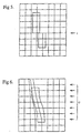
- the mesh x co-ordinates are altered which results in the underlying image being distorted. Rather than just the image area immediately under the mesh line being moved, which would result in a discontinuity - figure 5, adjacent mesh lines are also moved to produce a smooth distortion, Figure 6.
- the coarseness of the distortion mesh determines the impact of the 3D effect.
- the coarser the mesh the more splined other objects closer to the object being stretched are impacted. This results in a lower 3D impact in the resulting image.
- a finer mesh results in sharper edges to the objects, a higher impact 3D effect, but greater edge discontinuities.
- the order of the distortion mesh will for explanation purposes be assumed to be 16 X 16.
- Information on each subpoint on the mesh ie. co-ordinate positions after distorting) are encoded so as to produce background and foreground subpoints. For example, 4 bits can be used for the subpoint encoding which will result in 16 different levels, 4 background and 12 foreground.
- the format of the subpoint encoding can also be determined by experimentation and adjusted to suit the application.
- this mesh distortion process may be defined by a mathematical algorithm which would enable automatic processing of images.
- the matrix that is formed from the relative horizontal offset of each intersection point of the distorted mesh defines the Mesh Spatial Displacement (MSD) data.
- 3D images may be stored, transmitted, generated, edited, and manipulated by considering the 2D image and an associated MSD data file.
- a number of existing techniques can be used to add the MSD data to the 2D image such that it is not detected by the viewer and is compatible with existing video standards. These techniques include, but are not limited to:
- MSD data is small, estimated to be approximately 100 bytes per frame. This can be further compressed if necessary, for storage and transmission, by using standard data compression techniques such as run-length or differential encoding.
- the required data rate is also low. It is also possible to use spatial and temporal compression to further reduce the data required since the MSD data does not vary rapidly over a number of frames. The exact time relationship between the MSD data and its associated frame is not critical, a displacement error of one frame is probably acceptable.
- the MSD data could be sent over a number of frames ie. four frames with a quarter of the information in each frame.
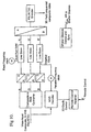
- FIG. 9 A block diagram indicating how a DDC decoder is incorporated in a video chain is shown in Figure 9.
- DDC encoded video which can be obtained via any existing video source i.e. terrestrial, satellite etc, is applied to the input of a DDC decoder.
- One output of the decoder is a standard video waveform (or video modulated radio frequency signal) that will drive a standard TV display and enable a viewer wearing shutter glasses, synchronised by the DDC decoder, to view a 3D image.
- Incoming video which can be PAL or NTSC
- In composite or S-video format is applied to a composite RGB or component video converter.
- Each of the RGB or component video outputs is applied to an analog to digital converter and the digital output fed to the input port of a dual port RAM line store.
- Each line of digital video data is entered into RAM at a constant speed. The data is read out of the line store at a rate determined by a variable frequency clock controlled by the output of the MSD decoder.
- the effect of reading out the line data from the RAM at a variable rate causes the resulting video to be stretched or compressed in accordance with the MSD data.
- the converted data Is then applied to a digital to analog converter and a PAL/NTSC encoder.
- the resulting 3D field sequential composite video signal is applied to the display. (Note: this process can also operate with the video signals read into the line stores at a variable rate and read out at a fixed rate. It is necessary to convert the incoming composite video signal to RGB or component video since, as the output from the line store is read out at a variable rate, the chrominance frequency would change and cause display errors.)
- DDC decoding may also be implemented using a field or frame store.
- the full mesh from the MSD data is restored with pixel distortions (lateral shifts) being calculated over the complete field or frame.
- the 3D stereoscopic image pair is then displayed from the resulting RGB or component video output.
- the shutter glasses controller provides an Infra-red light source that provides timing pulses for the shutter glasses.
- the controller is synchronised by the PAL/NTSC encoder. Additionally, the controller commands the shutter glasses to remain open during scenes that are not 3D encoded, or not suitable for 3D encoding, thus providing improved image quality during those portions of the video sequence.
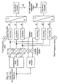
- Figure 11 shows the block diagram of a DDC decoder that produces 3D field parallel composite video outputs.
- the MSD decoder produces two variable speed clocks, one for the left and one for the right RAM line stores.
- This form of decoder is suitable for replacing the field stores in the applicants' existing autostereoscopic 3D displays. Note that this technique provides left and right video sources that are at the same field rate as the original 2D video source, ie. field sequential video output is produced.
- a non-field video output may be produced at the output at a higher resolution scanning rate than the 2D image.
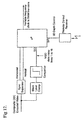
- FIG 12 shows a block diagram of one version of a MSD decoder.
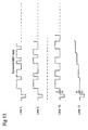
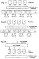
- the MSD data is encoded in the composite video signal in the first 16 lines of the video signal, Figure 13.
- Incoming composite video is fed to a sync separator which provides vertical and horizontal timing signals for the microprocessor. Additional the video is fed to a black level clamp circuit, comparator and level shifter. The output from the level shifter is a TTL level signal which contains the serial encoded MSD data on lines 1 to 16 of the video signal.
- the microprocessor loops waiting for a horizontal sync pulse, after determining the horizontal sync pulse for line 1 the microprocessor reads the next 16 bytes. A similar process is repeated on the following 15 lines until the MSD data has been read. Based upon the MSD data received the microprocessor provides the variable speed clock for the digital video line store on each subsequent video line. The microprocessor maintains an index to which video line is being processed by counting the line sync pulses.
- Depth perception of 3D images varies between viewers. Also when viewing 3D Images with shutter glasses the "strength" of the 3D Image requires adjustment with viewing distance.
- the strength of the 3D image can be altered with a remote control device which, via an algorithm applied by the microprocessor, allows the strength of the 3D image to be varied by the viewer.
- the algorithm alters the magnitude of each element in the MSD matrix thus altering the strength of the 3D effect. It is anticipated that once the preference for a particular viewer has been entered then this setting will be maintained by the decoder unit.
- DDC encoded video images There are many techniques for the real time generation of DDC encoded video images.
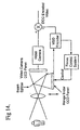
- the distance between the camera lens and an additional, range finding, Charge Coupled Device (CCD) array is altered - Figure 14. This will produce a series of frames with each object in the image at varying stages of focus.
- a sharpness detecting algorithm is then run across the series of frames and a sharpness index for each object in the image determined. We then determine on which frame each object was the sharpest, this indicates on which focal plane the object is on. This information is then used to form the MSD data.
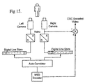
- Figure 15 indicates another technique whereby two video cameras are used to create separate left and right eye images.
- the luminance information from each camera is digitised and fed to a line store.
- An autocorrelator, or similar operation compares the bit patterns within the two line stores (left and right by 16 elements) and looks for a match.
- the difference (distance) between the video patterns, which represents objects in the image is used to produce the MSD data.
- One of the camera outputs is combined with the MSD data in real time to produce DDC encoded video.
- a stereoscopic video camera could be used in place of the two video cameras.
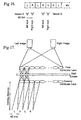
- DDC may be used to overcome a serious shortcoming of existing, non eye-tracking, autostereoscopic 3D multiviewer systems. These systems provide a 3D image by producing a repeating sequence of left-right images as illustrated in Figure 16. The distance between each successive image is 65 mm which is equal to the distance between the viewers eyes. Therefore a viewer located at position A will see a correctly sequenced 3D image.
- a second lenticular lens refocusses this image to form a vertical stripe of light at the viewing distance.
- a second projector, containing the right image also illuminates the first lenticular lens, however, due to a lateral displacement between the two projectors, the resulting right eye image, at the viewer plane, is displaced 65 mm from the left image. This sequence of alternate left right images, spaced 65 mm apart, is repealed.
- positions A and B work as before.
- position C produces a monoscopic image in the right eye and a black image in the left, which is still viewable without viewer discomfort.
- position D produces a monoscopic image but again without a reverse 3D effect.
- 50% of the viewer locations produce a correct 3D image and 50% a slightly inferior, although not objectionable, images and the reverse 3D effect has been eliminated.
- a multiviewer 3D, lenticular lens based, system using a DDC decoder is shown in Figure 20.
- DDC encoding/decoding will enable the production of a sequence of video images that represent the range of possible images from the extreme left of the original image to the extreme right, as follows:- [L, L 1 , L 2 ?? R 2 , R 1 , R]
- DDC Dynamic Depth Cueing
- the resultant 3D information can take the form of either a field sequential (ie. left/right) type video format, two separate video streams, a line be line system (ie. 1 line from left field, 1 line form right field), or some other format that is advantageous.
- the decoder could be located near to the viewing device (ie.TV) and essentially be a 'black box' that intercepts the transmission signal decodes it and then outputs it to the TV for viewing. Therefore upgrading of existing 2D pay TV or television network structures would be simplified by the addition of a 'black box' for each TV.
- Standard 2D video images which have been DDC encoded have the following characleristics:
Abstract
Description
- The present invention is generally directed towards stereoscopic image synthesis and more particularly toward a method of converting two dimensional (2D) images for further encoding, transmission and decoding for the purpose of stereoscopic image display on two dimensional (2D) or three dimensional (3D) stereoscopic displays systems.
- Recent improvements in technology in the areas of compact high performance video projection systems, image processing, digital video and liquid crystal panels have made possible many practical 3D display systems utilising both active and passive polarising glasses and both single and multi-viewer autostereoscopic displays.
- Three dimensional display systems have moved out of the arena of being technological curiosities and are now becoming practical display systems for entertainment, commercial and scientific applications. There has now emerged the requirement for 3D media to display on these devices. Traditionally there has been just two ways to produce this 3D media (i.e. media produced that contains image information for at least two separate views of the same scene from different perspectives). There are:
- 1) Generation of two separate views (usually in real time) by a computer.
- 2) Videoing or filming with two laterally displaced cameras in the case of computer generated images for usage in Computer Aided Design (CAD) systems, simulators or video game equipment, it is not a complex process to produce two separate images with different perspectives.
-
- The filming of movies utilising two laterally displaced cameras to produce 3D has been well understood for many years. However, there are many problems with this approach. It is considerably more difficult to film or video in 3D than in 2D because there are limits to the permissible distance between the nearest and farthest objects in the scene (practical 3D depth of field) as well as framing problems (such as near objects being seen on only one camera and thus highlighting the inaccuracy of the 3D image generation when re-played.
- A method using two laterally displaced cameras is described in US-A-4 704 627 (YUYAMA, et al) for example.
- Another problem is maintaining a smooth pan without causing false 3D artefacts due to latency between the images from the two cameras and so on.
- Because of the complexity, high cost ofproduction and implementation, and the fact that there are as yet still only a very small number of 3D display systems being produced for the domestic and commercial markets there has not been a large incentive for the major producers of films or videos to produce 3D media. However, if a technique was devised that would allow conventional 2D films to be re-processed into a 3D version then it would be possible to not only convert new films into 3D format for significantly less cost than filming them directly in 3D in the first place but it would also make possible the re-processing of the vast archives of 2D film and video material for re-release to both the cinema and video markets.
- It would however be advantageous to be able to convert an existing 2D image so that it can be viewed as a 3D image. One way of achieving this is to convert a single 2D image to two separate left and right images by a 'cut and paste' technique. In this technique, an object is 'cut' from the image and laterally displaced left or right then 'pasted' back onto the original image to produce the required separate images. This however results in a blank region in the area formally occupied by the object within the image. Such a method is described in US-A-4 925 294 (GESHWIND, et al) for example.
- This document covers some of the major algorithmic processes involved in the conversion of 2D media to 3D format, a new composite data format which is suitable for the communication and storage of this new 3D media. It also discusses several hardware implementations for the real-time encoding, transmission and decoding of this new 3D format.
- The main benefits of the technology is that there are significant cost saving and media supply advantages, i.e. only one camera has to be used for filing. Due to the nature of the 2D to 3D conversion process it is possible to package and transfer the image media virtually unchanged except for the addition of a small packet of 3D data that doesn't in any way encumber the final 2D display process. In fact it enables the images to be displayed on standard 2D televisions in 2D or 3D (usage of shutter glasses or similar required) without degradation of image quality whilst also allowing display on 3D televisions or other displays in 3D.
- The final stage of the 2D to 3D conversion process is completed in real-time at the receiver and thus the increased bandwidth requirements for displaying 3D images is local to the television decoder and does not adversely affect the channel handling capacity of the television carrier.
- According to the present invention from one aspect, there is provided a method of producing a 2D video signal encoded with conversion data to assist in the conversion of said 2D video signal to left and right eye images for a stereoscopic display, the method including:
- providing a 2D video signal which contains data pertaining to a 2D video image;
- producing conversion data which defines the displacement of respective selected points of said 2D video image for converting the image to left and right eye images for a stereoscopic display, such that both of said left and right eye images comprise portions which have been compressed and portions which have been stretched; and
- adding the conversion data to the 2D video signal to provide the encoded signal.
-
- Said conversion data could be transmitted in the blank lines at the top and/or bottom of a standard 2D image to be transmitted or in the horizontal sync period of a standard 2D image to be transmitted or in the horizontal overscan regions of each line of a standard 2D image to be transmitted.
- The method could include:
- producing video signals of video images from two separate viewpoints;
- comparing the video images from the separated viewpoints in order to produce said conversion data; and
- combining the video signal of the video images from one of said viewpoints with the conversion data to thereby produce the encoded video signal. The video signals could be produced from two separate cameras or left and right eye video images from a stereoscopic video camera.
-
- According to the present invention from another aspect, there is provided a method of producing left and right eye images for a stereoscopic display from an encoded 2D video signal, the method including:
- providing a 2D video signal which contains data pertaining to a 2D video image, said video signal being encoded with conversion data which defines the displacement of respective points of said 2D video image for converting the image to left and right eye images such that both of said left and right eye images comprise portions which have been compressed and portions which have been stretched;
- reading the conversion data from said video signal; and
- producing left and right eye images from the 2D video image for display by displacing objects within said 2D video image in accordance with said conversion data.
-
- Such a method could further include the steps of
- converting said 2D video image into RGB components;
- converting each component into a digital signal; and
- storing said digital signals prior to production of the left and right eye images.
-
- Said digital signals could be read out of storage at a variable rate as a function of the conversion data or said digital signals could be read into storage at a variable rate as a function of the conversion data.
- Said digital signals could be converted to analog for viewing on an analog system.
- Said conversion data could be separated from said video signal.
- According to the present invention from a further aspect, there is provided a system of producing a 2D video signal encoded with 3D conversion data, the system including:
- means for producing video signals of video images at two separate viewpoints;
- conversion means for producing conversion data, said conversion means receiving the video signals from said means and comparing the signals from the separate viewpoints to thereby produce the conversion data, said conversion data defining the displacement of respective points of one of said video images for converting the video image to left and right eye images for stereoscopic display such that both of said left eye and right eye images comprise portions which have been compressed and portions which have been stretched; and
- an encoder means for combining the video signal from said one video image with the conversion data from said conversion means to thereby produce an encoded video signal.
-
- Said means for producing video signals could comprise first and second video cameras displaced laterally relative to each other or a stereoscopic camera for capturing left and right eye video images.
- According to the invention from a further aspect, there is provided a decoder for decoding a video signal for providing a stereoscopic display, the signal providing a 2D video image and further including conversion data for converting the video image, the conversion data defining the displacement of respective points of the video image for converting the video image to an image for a stereoscopic display, wherein certain of the images produced are for viewing by the left eye of a viewer and the other images produced are for viewing by the right eye of said viewer, the decoder including:
- a) means for receiving the video signal;
- b) decoding means for reading the conversion data; and
- c) means for using the conversion data to convert the 2D video image into left and right eye images for stereoscopic display, such that both of said left and right eye images comprise portions which have been compressed and portions which have been stretched.
-
- Such a decoder could include:
- a) an RGB or component video converter for converting the video signal into separate video components thereof,
- b) analog to digital conversion means for converting each video component to a respective digital signal; and
- c) digital storage means for storing said digital signals.
-
- Said decoder could be adapted to control a variable frequency clock means controlling the read out rate of the digital storage means whereby the storage means are read out at a variable rate, to thereby convert the 2D image in accordance with the conversion data.
- Alternatively, said decoder could be adapted to control a variable frequency clock means controlling the read in rate of the digital storage means whereby the RGB or video components may be read into the storage means at a variable rate, to thereby convert the 2D image in accordance with the conversion data.
- The storage means could be in the form of a dual port RAM line store.
- The decoder could process a single video line or multiple video lines.
- In a decoder according to the invention, a digital to analog conversion means could be provided for converting the read out digital signal to a converted video signal to enable viewing on a viewing means. The decoder could include a parallel storage means for storing digital signal for the converted left and right video images respectively.
- Alternatively, the decoder could include a separation means for separating the conversion data from the video signal.
- According to the present invention from yet a further aspect, there is provided a stereoscopic image display system including:
- a) an encoder for encoding a video signal providing a 2D video image with conversion data, the conversion data defining displacement of respective points of the video image for converting the video image to an image for a stereoscopic display; and
- b) a decoder for separating the conversion data from the video signal and for converting the video signal as a function of the conversion data to convert the video image into left eye and right eye images such that both of said left and right eye images comprise portions which have been compressed and portions which have been stretched
-
- Such a system could further comprise adjustment means for selectively adjusting the displacement of the respective points to vary the level of stretching in the left and right eye images. The adjustment means could comprise a remote control device.
- The present invention also comprises a multiviewer stereoscopic display system wherein said system includes a decoder according to the invention. Such a multiviewer stereoscopic display system could comprise a plurality of projectors and wherein the decoder produces a series of images, each image being shown by a respective projector. The system could comprise a lenticular lens array to direct the images from the respective projectors.
- The present invention will now be described, by way of example, with reference to the accompanying drawings, in which:-
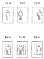
- Figure 1 shows an original image and conventional left and right images for providing a 3D or stereoscopic image;
- Figure 2 shows an original image and left and right images for providing a 3D image produced using a cut and paste technique;
- Figure 3 shows an original image and an image generated by a Dynamic Depth Cueing (DDC) method according to the present invention;
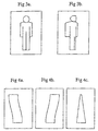
- Figure 4 shows a left and right image and the resultant 3D image according to the present invention;
- Figure 5 shows an image distorted discontinuously by a distortion mesh;
- Figure 6 shows an image distorted continuously by a distortion mesh;
- Figure 7 shows an example of Mesh Spatial Displacement (MSD) data for a left and right mesh;
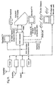
- Figure 8 shows a flow chart illustrating how MSD data is added to a video image according to the present invention;
- Figure 9 shows a block diagram indicating how a DDC decoder is incorporated in a video chain according to the present invention;
- Figure 10 shows a block diagram indicating a possible implementation of a DDC decoder unit according to the present invention providing field sequential composite video outputs;
- Figure 11 shows a block diagram of another possible implementation of a DDC decoder unit according to the present invention providing field parallel composite video outputs;
- Figure 12 shows a block diagram of one version of a MSD decoder according to the present invention;
- Figure 13 shows how MSD data is encoded in the composite video signal;
- Figure 14 shows a block diagram of an arrangement for providing real time generated DDC encoded video images;
- Figure 15 shows a block diagram of an alternative arrangement for providing real time generated DDC encoded video images;
- Figure 16 shows the principle of operation of multi-viewer 3D systems;
- Figure 17 shows a block diagram illustrating the principle of operation of a lentioular lens based 3D system;
- Figure 18 and 19 respectively show a multi-projector system using a lenticular lens assembly; and
- Figure 20 shows a multi-projector system Incorporating a DDC decoder according to the present invention.
-
- The method according to the present invention for enabling 2D or "monoscopic" video signals to be converted to 3D or "stereoscopic" video signals is referred to as Dynamic Depth Cueing (DDC) in the following description and embraces the following but is not limited to these techniques:
- a) 3D GENERATION - A technique and procedure for converting 2D
images
into 3D stereoscopic image pairs and for producing the 3D conversion data. - b) 3D SCRIPTING - A technique to describe the changes required to be made to a 2D image in order to convert it to a 3D stereoscopic image pair. Describes which objects are selected, how they are processed and provides for a means of storage of 3D data.
- c) 3D DATA ENCODING - A technique for adding information to a 2D video image in a defined format . The resulting modified video is compatible with existing video recording, editing, transmission and receiving systems.
- d) 3D STANDARDISED PROTOCOL - The 3D Conversion data is added to the 2D video using a defined data format or standardised protocol. This protocol may well become a world-wide standard for adding 3D Conversion data to 2D transmissions.
- e) 3D DATA DECODING - A technique for receiving the 2D video image plus conversion data and to extract the information added to a 2D video image so that a 3D stereoscopic Image pair may be synthesised.
- f) 3D SYNTHESIS - A technique to manipulate the 2D video image using the conversion data to synthesise a 3D stereoscopic image pair.
-
- In order to convert a 2D image to a simulated 3D image it is necessary to modify the original image to produce two slightly different images and present these separate images to the left and right eyes independently.
The modification to the original image consists of a lateral shift of objects within the image plane (located at the projection or viewing screen) in order to give the impression of depth. - To make an object in an image appear farther away from the viewer, with respect to the image plane, then it is necessary to present the object within the image to the left eye with a slight left lateral shift and that to the right eye with a slight right lateral shift. This is illustrated in Figure 1. To make an object appear to the viewer to be closer, it is necessary to shift the object within the image for the left eye laterally to the right and the object within the image for the right eye laterally to the left. For an object to be positioned at the image plane the object Is placed in the image at the same position for both eyes.
- When viewing objects in the real world, a viewer also makes use of focus information. However, with simulated 3D this information is not present and if the lateral shifts are made too great, particularly in order to bring an object closer to the viewer, then the object appears to break into two separate images and the 3D effect is lost.
- The left and right images can be produced using a computer. The image is firstly digitised using a video digitiser and the resulting data stored in memory. The two new images can then be generated.
- The simplest way to generate the new left and right images with the required lateral shift is to "cut" the objects from the image and "paste" them back with the necessary lateral displacement, this will be referred to as the 'cut and paste" technique. This can be done by first defining the position of an object to be "moved" by Identifying It then "cutting" the object from the image and moving It laterally.
- The problem with this simple technique is that once the selected object is moved the background is also removed and a blank region in the background results, see Figure 2.
- According to the present invention, an object within an image is "stretched" to provide the necessary lateral shift and retain the original background detail. The resulting lateral distortions of the image are smoothed mathematically so that the resultant effect is perceived as 'real' 3D with little or no visual artefacts.
- To better visualise the effect of this stretching on the image, imagine that the image to be converted has been printed onto a thin sheet of rubber. It is possible to pick a point on the surface of the image, adjacent to an object, and stretch it into a new position, to the right of its original position for example. The section of the image to the right of the object is therefore compressed and that to the left stretched, see Figure 3. To the viewer the object now appears distorted if viewed by both eyes.
- However, if a similar but oppositely stretched image is presented to the other eye, then the viewer does not see a distorted image, rather an object that has 3D characteristics. This is illustrated in Figure 4.
- The "stretching" of an object within an image can be undertaken electronically. The objects of Interest in each video frame are firstly identified by outlining them. For each object a depth or mesh distortion characteristic is also defined. The stretching can be conducted by enabling an operator to stretch the image and view the effect of the resulting 3D image in real time. Operator skill and artistic intervention can be used to determine the 3D impact of the resulting image and subsequent video sequence. Whilst individual video frames could be converted manually (ie. non real time) we also envisage automatically (ie. real time) converting a series of related frames that form a video "clip". The operator will define the start and end frames of the video clip to be converted. They will also determine the relative depth of each object, relative to the image plane, in the start and end frames. The video clip will be processed using the start and end positions and depth of each object In the clip, to interpolate the required stretching or manipulation for the intermediate frames.
- In the case of multiple overlapping objects which have different depths, foreground objects are given priority. This is inherently the case, since the original 2D image has been captured with a single camera, thus the pixel information has automatically been prioritised to the foreground.
- This "stretching" of the image can be undertaken electronically by manipulating the digitised image. A mesh (grid) is temporarily placed over the image to be distorted such that, prior to distortion, the co-ordinates of each row and column of the mesh is 0,0. The mesh x co-ordinates are altered which results in the underlying image being distorted. Rather than just the image area immediately under the mesh line being moved, which would result in a discontinuity - figure 5, adjacent mesh lines are also moved to produce a smooth distortion, Figure 6.
- The coarseness of the distortion mesh determines the impact of the 3D effect. The coarser the mesh the more splined other objects closer to the object being stretched are impacted. This results in a lower 3D impact in the resulting image. A finer mesh results in sharper edges to the objects, a
higher impact 3D effect, but greater edge discontinuities. The order of the distortion mesh will for explanation purposes be assumed to be 16X 16. Information on each subpoint on the mesh (ie. co-ordinate positions after distorting) are encoded so as to produce background and foreground subpoints. For example, 4 bits can be used for the subpoint encoding which will result in 16 different levels, 4 background and 12 foreground. The format of the subpoint encoding can also be determined by experimentation and adjusted to suit the application. - Alternatively, this mesh distortion process may be defined by a mathematical algorithm which would enable automatic processing of images.
- Note that once the mesh distortions for the left eye have been determined, then the co-ordinates of the distortions for the right eye are simply obtained by scalar multiplication of the matrix by -1 ( ie. shifted In the opposite lateral direction by the same amount) and can be calculated automatically. This is illustrated in Figure 7.
- The matrix that is formed from the relative horizontal offset of each intersection point of the distorted mesh defines the Mesh Spatial Displacement (MSD) data.
- In order to fully define and reproduce the resultant 3D image all that is necessary is to provide the original, unaltered, 2D image and the MSD data. Thus 3D images may be stored, transmitted, generated, edited, and manipulated by considering the 2D image and an associated MSD data file.
- It is therefore possible to store and transmit 3D images over conventional 2D video systems by encoding MSD data within each video frame. Since the original 2D video image is stored and can be transmitted without alteration, the resulting video is fully compatible with all existing video and television systems. Existing 2D TV receivers will display a normal picture.
- A number of existing techniques can be used to add the MSD data to the 2D image such that it is not detected by the viewer and is compatible with existing video standards. These techniques include, but are not limited to:
- a) inserting the MSD information in the spare lines at the top and bottom of the picture that are set at black level, ie. in a similar manner to the addition of "Teletext" data;
- b) in the unseen over-scan region at the left and right of each Image;
- c) In the horizontal sync period, along the lines of the British Broadcasting Corporation "sound in sync" system.
-
- In the future, with the introduction of digital HDTV, spare digital data frames will be available to insert the MSD data.
- The process of adding the MSD data to a 2D video image to form a DDC encoded video frame is illustrated in Figure 8.
- The amount of MSD data is small, estimated to be approximately 100 bytes per frame. This can be further compressed if necessary, for storage and transmission, by using standard data compression techniques such as run-length or differential encoding.
- Because of the small amount of data, the required data rate is also low. It is also possible to use spatial and temporal compression to further reduce the data required since the MSD data does not vary rapidly over a number of frames. The exact time relationship between the MSD data and its associated frame is not critical, a displacement error of one frame is probably acceptable.
- Again due to the small amount of data, low data rate and non-critical alignment, the MSD data could be sent over a number of frames ie. four frames with a quarter of the information in each frame.
- A block diagram indicating how a DDC decoder is incorporated in a video chain is shown in Figure 9. DDC encoded video, which can be obtained via any existing video source i.e. terrestrial, satellite etc, is applied to the input of a DDC decoder. One output of the decoder is a standard video waveform (or video modulated radio frequency signal) that will drive a standard TV display and enable a viewer wearing shutter glasses, synchronised by the DDC decoder, to view a 3D image.
- Additionally outputs are available from the DDC decoder to drive other 3D display devices such as Virtual Reality headsets or an autostereoscopic display as described in Australian application No. 66718/94.
- One possible implementation of the DDC decoder is shown in Figure 10. Incoming video, which can be PAL or NTSC, In composite or S-video format, is applied to a composite RGB or component video converter. Each of the RGB or component video outputs is applied to an analog to digital converter and the digital output fed to the input port of a dual port RAM line store. Each line of digital video data is entered into RAM at a constant speed. The data is read out of the line store at a rate determined by a variable frequency clock controlled by the output of the MSD decoder.
- The effect of reading out the line data from the RAM at a variable rate causes the resulting video to be stretched or compressed in accordance with the MSD data.
- The converted data Is then applied to a digital to analog converter and a PAL/NTSC encoder. The resulting 3D field sequential composite video signal is applied to the display. (Note: this process can also operate with the video signals read into the line stores at a variable rate and read out at a fixed rate. It is necessary to convert the incoming composite video signal to RGB or component video since, as the output from the line store is read out at a variable rate, the chrominance frequency would change and cause display errors.)
- DDC decoding may also be implemented using a field or frame store. In this case the full mesh from the MSD data is restored with pixel distortions (lateral shifts) being calculated over the complete field or frame.
- The 3D stereoscopic image pair is then displayed from the resulting RGB or component video output.
- The shutter glasses controller provides an Infra-red light source that provides timing pulses for the shutter glasses. The controller is synchronised by the PAL/NTSC encoder. Additionally, the controller commands the shutter glasses to remain open during scenes that are not 3D encoded, or not suitable for 3D encoding, thus providing improved image quality during those portions of the video sequence.
- Figure 11 shows the block diagram of a DDC decoder that produces 3D field parallel composite video outputs. The MSD decoder produces two variable speed clocks, one for the left and one for the right RAM line stores. This form of decoder is suitable for replacing the field stores in the applicants' existing autostereoscopic 3D displays. Note that this technique provides left and right video sources that are at the same field rate as the original 2D video source, ie. field sequential video output is produced.
- Alternatively a non-field video output may be produced at the output at a higher resolution scanning rate than the 2D image.
- Figure 12 shows a block diagram of one version of a MSD decoder. In this case it is assumed that the MSD data is encoded in the composite video signal in the first 16 lines of the video signal, Figure 13. Incoming composite video is fed to a sync separator which provides vertical and horizontal timing signals for the microprocessor. Additional the video is fed to a black level clamp circuit, comparator and level shifter. The output from the level shifter is a TTL level signal which contains the serial encoded MSD data on
lines 1 to 16 of the video signal. The microprocessor loops waiting for a horizontal sync pulse, after determining the horizontal sync pulse forline 1 the microprocessor reads the next 16 bytes. A similar process is repeated on the following 15 lines until the MSD data has been read. Based upon the MSD data received the microprocessor provides the variable speed clock for the digital video line store on each subsequent video line. The microprocessor maintains an index to which video line is being processed by counting the line sync pulses. - Depth perception of 3D images varies between viewers. Also when viewing 3D Images with shutter glasses the "strength" of the 3D Image requires adjustment with viewing distance. The strength of the 3D image can be altered with a remote control device which, via an algorithm applied by the microprocessor, allows the strength of the 3D image to be varied by the viewer. The algorithm alters the magnitude of each element in the MSD matrix thus altering the strength of the 3D effect. It is anticipated that once the preference for a particular viewer has been entered then this setting will be maintained by the decoder unit.
- There are many techniques for the real time generation of DDC encoded video images. In one such technique the distance between the camera lens and an additional, range finding, Charge Coupled Device (CCD) array is altered - Figure 14. This will produce a series of frames with each object in the image at varying stages of focus. A sharpness detecting algorithm is then run across the series of frames and a sharpness index for each object in the image determined. We then determine on which frame each object was the sharpest, this indicates on which focal plane the object is on. This information is then used to form the MSD data.
- Figure 15 indicates another technique whereby two video cameras are used to create separate left and right eye images. The luminance information from each camera is digitised and fed to a line store. An autocorrelator, or similar operation, compares the bit patterns within the two line stores (left and right by 16 elements) and looks for a match. The difference (distance) between the video patterns, which represents objects in the image, is used to produce the MSD data. One of the camera outputs is combined with the MSD data in real time to produce DDC encoded video.
- Alternatively a stereoscopic video camera could be used in place of the two video cameras.
- DDC may be used to overcome a serious shortcoming of existing, non eye-tracking, autostereoscopic 3D multiviewer systems. These systems provide a 3D image by producing a repeating sequence of left-right images as illustrated in Figure 16. The distance between each successive image is 65 mm which is equal to the distance between the viewers eyes. Therefore a viewer located at position A will see a correctly sequenced 3D image.
- However, should the viewer move laterally 32 mm, or be at position B, then the left image will be seen by the right eye and the right image by the left eye. ie. the viewer sees a 'reverse 3D" image. The reverse 3D image is very uncomfortable to view and after a short while causes viewer distress ie. headache.
Most multiviewer autostereoscopic system have this shortcoming. In particular those based upon lenticular lenses and grid type image separators. A multiviewer, lenticular lens based, autostereoscopic system is illustrated in Figure 17. The image from the left projector passes through the first lenticular lens and is focused on the surface of a matt screen. A second lenticular lens refocusses this image to form a vertical stripe of light at the viewing distance. A second projector, containing the right image, also illuminates the first lenticular lens, however, due to a lateral displacement between the two projectors, the resulting right eye image, at the viewer plane, is displaced 65 mm from the left image. This sequence of alternate left right images, spaced 65 mm apart, is repealed. - A viewer in the correct position views a correct 3D image, however, reverse 3D images are also presented should the viewer move or be incorrectly positioned as explained above.
- In practice, when first sitting down to view a lenticular lens based 3D system it is difficult for the viewer to determine if a correct or reverse 3D image is being viewed. It is not until discomfort is felt that the viewer is aware of being incorrectly positioned.
- Additionally, it is difficult for a viewer to maintain the correct viewing position for an extended period of time. It is also necessary that the viewer be positioned the correct distance from the second lenticular lens, since if viewed at the incorrect distance morae fringing and cross talk effects tend to occur.
- An additional problem with lenticular lens based system is resolution. The resolution is limited by the pitch of each "lens-let" in the overall lenticular lens, which is in the order of 1 mm across.
- Instead of projecting just left and right images, consider a lenticular lens based system using a number of projectors, say four, such as to produce a series of
images - This is a substantial improvement over the previous left right system since now an acceptable 3D image Is viewable over 3 times the lateral distance. Note that, as with the previous left right system, a viewer will not be aware, until discomfort is felt, that position D is providing a reverse 3D image.
- If now projector four Is replaced with a "null" image (black), Figure 19, then positions A and B work as before. position C produces a monoscopic image in the right eye and a black image in the left, which is still viewable without viewer discomfort. Similarly position D produces a monoscopic image but again without a reverse 3D effect. We thus have a system where 50% of the viewer locations produce a correct 3D image and 50% a slightly inferior, although not objectionable, images and the reverse 3D effect has been eliminated.
- By increasing the number of projectors, and including a null image, the lateral distance over which a correct 3D image can be viewed is increased and the reverse 3D effect has been eliminated.
- It is however not considered practical to implement such a multi-projector system, primarily because the transmission/recording bandwidth necessary to provide video images to each projector becomes impractical as the number of projectors is increased.
- The limitations of this approach can be overcome by transmitting a DDC encoded 2D image and using DDC to synthesise the required number of projection Images. Whilst a wide bandwidth is required within the DDC decoder, the original 2D bandwidth is maintained at the transmitter and/or recording equipment.
- A
multiviewer 3D, lenticular lens based, system using a DDC decoder is shown in Figure 20. - DDC encoding/decoding will enable the production of a sequence of video images that represent the range of possible images from the extreme left of the original image to the extreme right, as follows:-
[L, L1, L2 ...... R2, R1, R] - In summary some of the applications may be described by:
- DDC, or Dynamic Depth Cueing, is a term for a form of data derived from the 2D to 3D conversion process which is in an intermediary stage of conversion. At this stage the data consists of the original video signal and a data packet (encoded either in digital or analogue form) such that this additional data is all that is required to instruct specific electronics hardware and/or software to complete the conversion task. The resultant 3D information can take the form of either a field sequential (ie. left/right) type video format, two separate video streams, a line be line system (ie. 1 line from left field, 1 line form right field), or some other format that is advantageous.
- Through careful design of the format of the conversion data packet it is possible to include this additional data such that it is not noticed when displayed on a standard TV. Thus it becomes possible to introduce 3D television transmissions without upsetting the existing television infra-structure. The decoder could be located near to the viewing device (ie.TV) and essentially be a 'black box' that intercepts the transmission signal decodes it and then outputs it to the TV for viewing. Therefore upgrading of existing 2D pay TV or television network structures would be simplified by the addition of a 'black box' for each TV.
- In the provision of media for MULTI-IMAGE type auto-stereoscopic 3D displays systems. These systems rely on the provision of multiple images with slightly differing perspective views. They can be quite effective if the number of different views is large ( Say 8-16 ) in that they allow true multiviewer capability. Their major drawback is that because they require many different views to all be available at the same time the provision of the media is extremely difficult even utilising sophisticated video compression techniques. However, if a DDC decoder is used to generate the 3D media it becomes possible to generate as many individual perspective views as are required, and as this image equipment, ie. TV's and video recorders, as normal 2D images. The viewer is not aware of any changes to the transmitted image.
- Standard 2D video images which have been DDC encoded have the following characleristics:
- DDC encoded 2D images can be received on standard video equipment le. TV's and video recorders, as normal 2D images. The viewer is not aware of any changes to the transmitted image.
- DDC encoded Images are fully compatible with all existing video, editing, recording, receiving and transmission systems and technologies. Thus DDC encoded 2D video images are transparent to all existing analog video and television technologies.
- DDC encoded 2D video can be introduced to the market place in a similar manner to the introduction of colour TV and stereo sound. Only TV sets fitled with DDC decoders (with viewers using appropriate viewing glasses), or 3D TV's, will display the 3D images.
- DDC encoding enables seamless transition between scenes that will benefit from 3D encoding and those that are more beneficially displayed in 2D. This transition is not noticed by the viewer.
- DDC encoded video may be displayed on all existing 3D displays and is suitable for multi-viewer systems.
- DDC encoding retains the original video source's line and field standards.
- DDC encoding does not reduce the image update frequency as is the case when encoding 3D video images in Left/Right field sequential format.
Claims (32)
- A method of producing a 2D video signal encoded with conversion data to assist in the conversion of said 2D video signal to left and right eye images for a stereoscopic display, the method including:providing a 2D video signal which contains data pertaining to a 2D video image;producing conversion data which defines the displacement of respective selected points of said 2D video image for converting the image to left and right eye images for a stereoscopic display, such that both of said left and right eye images comprise portions which have been compressed and portions which have been stretched; andadding the conversion data to the 2D video signal to provide the encoded signal.
- A method as claimed in claim 1 wherein said conversion data is transmitted in the blank lines at the top and/or bottom of a standard 2D image to be transmitted.
- A method as claimed in claim 1 wherein said conversion data is transmitted in the horizontal sync period of a standard 2D image to be transmitted.
- A method as claimed in claim 1 wherein said conversion data is transmitted in the horizontal overscan regions of each line of a standard 2D image to be transmitted.
- A method according to any preceding claim wherein said method inciudes:producing video signals of video images from two separate viewpoints;comparing the video images from the separated viewpoints in order to produce said conversion data; andcombining the video signal of the video images from one of said viewpoints with the conversion data to thereby produce the encoded video signal.
- A method according to claim 5 wherein said video signals are produced from two separate cameras.
- A method according to claim 5 wherein said video signals are left and right eye video images from a stereoscopic video camera.
- A method of producing left and right eye images for a stereoscopic display from an encoded 2D video signal, the method including:providing a 2D video signal which contains data pertaining to a 2D video image, said video signal being encoded with conversion data which defines the displacement of respective points of said 2D video image for converting the image to left and right eye images such that both of said left and right eye images comprise portions which have been compressed and portions which have been stretched;reading the conversion data from said video signal; andproducing left and right eye images from the 2D video image for display by displacing objects within said 2D video image in accordance with said conversion data.
- A method as claimed in claim 8 wherein said method further includes the steps of:converting said 2D video image into RGB components;converting each component into a digital signal; andstoring said digital signals prior to production of the left and right eye images.
- A method as claimed in claims 8 or claim 9 wherein said digital signals are read out of storage at a variable rate as a function of the conversion data.
- A method as claimed in claim 8 or claim 9 wherein said digital signals are read into storage at a variable rate as a function of the conversion data.
- A method as claimed in any one of claims 8 to 11 wherein said digital signals are converted to analog for viewing on an analog system.
- A method as claimed in any one of claims 8 to 12 wherein said conversion data is separated from said video signal.
- A system of producing a 2D video signal encoded with 3D conversion data, the system including:means for producing video signals of video images at two separate viewpoints;conversion means for producing conversion data, said conversion means receiving the video signals from said means and comparing the signals from the separate viewpoints to thereby produce the conversion data, said conversion data defining the displacement of respective points of one of said video images for converting the video image to left and right eye images for stereoscopic display such that both of said left eye and right eye images comprise portions which have been compressed and portions which have been stretched; andan encoder means for combining the video signal from said one video image with the conversion data from said conversion means to thereby produce an encoded video signal.
- A system according to claim 14 wherein said means comprises first and second video cameras displaced laterally relative to each other.
- A system according to claim 14 wherein said means comprises a stereoscopic camera for capturing left and right eye video images.
- A decoder for decoding a video signal for providing a stereoscopic display, the signal providing a 2D video image and further including conversion data for converting the video image, the conversion data defining the displacement of respective points of the video image for converting the video image to an image for a stereoscopic display, wherein certain of the images produced are for viewing by the left eye of a viewer and the other images produced are for viewing by the right eye of said viewer, the decoder including:a) means for receiving the video signal;b) decoding means for reading the conversion data; andc) means for using the conversion data to convert the 2D video image into left and right eye images for stereoscopic display, such that both of said left and right eye images comprise portions which have been compressed and portions which have been stretched.
- A decoder as claimed in claim 17, wherein said decoder includes:a) an RGB or component video converter for converting the video signal into separate video components thereof;b) analog to digital conversion means for converting each video component to a respective digital signal; andc) digital storage means for storing said digital signals.
- A decoder as claimed in claim 17 or claim 18, wherein said decoder is adapted to control a variable frequency clock means controlling the read out rate of the digital storage means whereby the storage means are read out at a variable rate, to thereby convert the 2D image in accordance with the conversion data.
- A decoder as claimed in claim 17 or claim 18, wherein said decoder is adapted to control a variable frequency clock means controlling the read in rate of the digital storage means whereby the RGB or video components may be read into the storage means at a variable rate, to thereby convert the 2D image in accordance with the conversion data.
- A decoder as claimed in any one of claims 17 to 20 wherein the storage means is in the form of a dual port RAM line store.
- A decoder as claimed in any one of claims 17 to 21 wherein the decoder processes a single video line.
- A decoder as claimed in any one of claims 17 to 21 wherein the decoder processes multiple video lines.
- A decoder as claimed in any one of claims 17 to 23 wherein a digital to analog conversion means is provided for converting the read out digital signal to a converted video signal to enable viewing on a viewing means.
- A decoder as claimed in any one of claims 17 to 23 wherein said decoder includes a parallel storage means for storing digital signal for the converted left and right video images respectively.
- A decoder as claimed in any one of claims 17 to 23 wherein said decoder includes a separation means for separating the conversion data from the video signal.
- A stereoscopic image display system including:a) an encoder for encoding a video signal providing a 2D video image with conversion data, the conversion data defining displacement of respective points of the video image for converting the video image to an image for a stereoscopic display; andb) a decoder for separating the conversion data from the video signal and for converting the video signal as a function of the conversion data to convert the video image into left eye and right eye images such that both of said left and right eye images comprise portions which have been compressed and portions which have been stretched.
- A stereoscopic display system according to claim 27 further comprising adjustment means for selectively adjusting the displacement of the respective points to vary the level of stretching in the left and right eye images.
- A stereoscopic display system according to claim 28 wherein the adjustment means comprises a remote control device.
- A multiviewer stereoscopic display system wherein said system includes a decoder according to claim 17.
- A multiviewer stereoscopic display system according to claim 30 comprising a plurality of projectors and wherein the decoder produces a series of images, each image being shown by a respective projector.
- A multiviewer stereoscopic display system according to claim 31 comprising a lenticular lens array to direct the images from the respective projectors.
Applications Claiming Priority (3)
| Application Number | Priority Date | Filing Date | Title |
|---|---|---|---|
| AUPN732395 | 1995-12-22 | ||
| AUPN7323A AUPN732395A0 (en) | 1995-12-22 | 1995-12-22 | Image conversion and encoding techniques |
| EP96941530A EP0868818B1 (en) | 1995-12-22 | 1996-12-20 | Image conversion and encoding techniques |
Related Parent Applications (1)
| Application Number | Title | Priority Date | Filing Date |
|---|---|---|---|
| EP96941530A Division EP0868818B1 (en) | 1995-12-22 | 1996-12-20 | Image conversion and encoding techniques |
Publications (3)
| Publication Number | Publication Date |
|---|---|
| EP1187494A2 EP1187494A2 (en) | 2002-03-13 |
| EP1187494A3 EP1187494A3 (en) | 2002-04-10 |
| EP1187494B1 true EP1187494B1 (en) | 2004-04-14 |
Family
ID=3791642
Family Applications (2)
| Application Number | Title | Priority Date | Filing Date |
|---|---|---|---|
| EP96941530A Expired - Lifetime EP0868818B1 (en) | 1995-12-22 | 1996-12-20 | Image conversion and encoding techniques |
| EP01127686A Expired - Lifetime EP1187494B1 (en) | 1995-12-22 | 1996-12-20 | Image conversion and encoding techniques |
Family Applications Before (1)
| Application Number | Title | Priority Date | Filing Date |
|---|---|---|---|
| EP96941530A Expired - Lifetime EP0868818B1 (en) | 1995-12-22 | 1996-12-20 | Image conversion and encoding techniques |
Country Status (14)
| Country | Link |
|---|---|
| US (2) | US6477267B1 (en) |
| EP (2) | EP0868818B1 (en) |
| JP (3) | JP3819434B2 (en) |
| CN (1) | CN1136737C (en) |
| AT (2) | ATE264527T1 (en) |
| AU (2) | AUPN732395A0 (en) |
| CA (2) | CA2435044C (en) |
| DE (2) | DE69628662T2 (en) |
| DK (1) | DK1187494T3 (en) |
| ES (1) | ES2219473T3 (en) |
| HK (2) | HK1010624A1 (en) |
| MY (1) | MY114040A (en) |
| PT (1) | PT1187494E (en) |
| WO (1) | WO1997024000A1 (en) |
Cited By (14)
| Publication number | Priority date | Publication date | Assignee | Title |
|---|---|---|---|---|
| US7907793B1 (en) | 2001-05-04 | 2011-03-15 | Legend Films Inc. | Image sequence depth enhancement system and method |
| US8160390B1 (en) | 1970-01-21 | 2012-04-17 | Legend3D, Inc. | Minimal artifact image sequence depth enhancement system and method |
| US8385684B2 (en) | 2001-05-04 | 2013-02-26 | Legend3D, Inc. | System and method for minimal iteration workflow for image sequence depth enhancement |
| US8730232B2 (en) | 2011-02-01 | 2014-05-20 | Legend3D, Inc. | Director-style based 2D to 3D movie conversion system and method |
| US9007404B2 (en) | 2013-03-15 | 2015-04-14 | Legend3D, Inc. | Tilt-based look around effect image enhancement method |
| US9007365B2 (en) | 2012-11-27 | 2015-04-14 | Legend3D, Inc. | Line depth augmentation system and method for conversion of 2D images to 3D images |
| US9241147B2 (en) | 2013-05-01 | 2016-01-19 | Legend3D, Inc. | External depth map transformation method for conversion of two-dimensional images to stereoscopic images |
| US9282321B2 (en) | 2011-02-17 | 2016-03-08 | Legend3D, Inc. | 3D model multi-reviewer system |
| US9286941B2 (en) | 2001-05-04 | 2016-03-15 | Legend3D, Inc. | Image sequence enhancement and motion picture project management system |
| US9288476B2 (en) | 2011-02-17 | 2016-03-15 | Legend3D, Inc. | System and method for real-time depth modification of stereo images of a virtual reality environment |
| US9342861B2 (en) | 2011-04-19 | 2016-05-17 | Deluxe 3D Llc | Alternate viewpoint rendering |
| US9407904B2 (en) | 2013-05-01 | 2016-08-02 | Legend3D, Inc. | Method for creating 3D virtual reality from 2D images |
| US9438878B2 (en) | 2013-05-01 | 2016-09-06 | Legend3D, Inc. | Method of converting 2D video to 3D video using 3D object models |
| US9547937B2 (en) | 2012-11-30 | 2017-01-17 | Legend3D, Inc. | Three-dimensional annotation system and method |
Families Citing this family (123)
| Publication number | Priority date | Publication date | Assignee | Title |
|---|---|---|---|---|
| US6108005A (en) * | 1996-08-30 | 2000-08-22 | Space Corporation | Method for producing a synthesized stereoscopic image |
| AUPO894497A0 (en) * | 1997-09-02 | 1997-09-25 | Xenotech Research Pty Ltd | Image processing method and apparatus |
| EP2252071A3 (en) * | 1997-12-05 | 2017-04-12 | Dynamic Digital Depth Research Pty. Ltd. | Improved image conversion and encoding techniques |
| US6515659B1 (en) | 1998-05-27 | 2003-02-04 | In-Three, Inc. | Method and system for creating realistic smooth three-dimensional depth contours from two-dimensional images |
| US7116323B2 (en) | 1998-05-27 | 2006-10-03 | In-Three, Inc. | Method of hidden surface reconstruction for creating accurate three-dimensional images converted from two-dimensional images |
| US6208348B1 (en) | 1998-05-27 | 2001-03-27 | In-Three, Inc. | System and method for dimensionalization processing of images in consideration of a pedetermined image projection format |
| US7116324B2 (en) | 1998-05-27 | 2006-10-03 | In-Three, Inc. | Method for minimizing visual artifacts converting two-dimensional motion pictures into three-dimensional motion pictures |
| WO2000019265A1 (en) * | 1998-09-30 | 2000-04-06 | Siemens Aktiengesellschaft | Arrangement and method for stereoscopic representation of an object |
| US20020051491A1 (en) * | 1998-11-20 | 2002-05-02 | Kiran Challapali | Extraction of foreground information for video conference |
| US6363362B1 (en) | 1999-04-07 | 2002-03-26 | Checkfree Services Corporation | Technique for integrating electronic accounting systems with an electronic payment system |
| US6807295B1 (en) * | 1999-06-29 | 2004-10-19 | Fuji Photo Film Co., Ltd. | Stereoscopic imaging apparatus and method |
| US20030061188A1 (en) * | 1999-12-23 | 2003-03-27 | Linus Wiebe | General information management system |
| US7184002B2 (en) * | 2001-03-29 | 2007-02-27 | Stereographics Corporation | Above-and-below stereoscopic format with signifier |
| KR20020081661A (en) * | 2001-04-19 | 2002-10-30 | 주식회사 오픈비주얼 | Method and Apparatus for Visualization and Manipulation of Real 3-D Objects in Networked Environments |
| CA2478671C (en) | 2002-03-13 | 2011-09-13 | Imax Corporation | Systems and methods for digitally re-mastering or otherwise modifying motion pictures or other image sequences data |
| CA2380105A1 (en) * | 2002-04-09 | 2003-10-09 | Nicholas Routhier | Process and system for encoding and playback of stereoscopic video sequences |
| JP4954473B2 (en) * | 2002-07-31 | 2012-06-13 | コーニンクレッカ フィリップス エレクトロニクス エヌ ヴィ | Method and apparatus for encoding a digital video signal |
| US20040032489A1 (en) * | 2002-08-13 | 2004-02-19 | Tyra Donald Wayne | Method for displaying a visual element of a scene |
| US7660356B2 (en) * | 2002-10-02 | 2010-02-09 | Lsi Corporation | Compressed video format with partial picture representation |
| JP3970192B2 (en) * | 2003-02-14 | 2007-09-05 | シャープ株式会社 | Projection image correction apparatus and projector apparatus |
| WO2005013623A1 (en) * | 2003-08-05 | 2005-02-10 | Koninklijke Philips Electronics N.V. | Multi-view image generation |
| WO2005067319A1 (en) * | 2003-12-25 | 2005-07-21 | Brother Kogyo Kabushiki Kaisha | Image display device and signal processing device |
| US7660472B2 (en) * | 2004-02-10 | 2010-02-09 | Headplay (Barbados) Inc. | System and method for managing stereoscopic viewing |
| US20050207486A1 (en) * | 2004-03-18 | 2005-09-22 | Sony Corporation | Three dimensional acquisition and visualization system for personal electronic devices |
| FR2873214B1 (en) * | 2004-07-13 | 2008-10-10 | Canon Res Ct France S A S Soc | METHOD AND DEVICE FOR OBTAINING STEREOSCOPIC SIGNAL |
| US7542034B2 (en) * | 2004-09-23 | 2009-06-02 | Conversion Works, Inc. | System and method for processing video images |
| US20080259073A1 (en) * | 2004-09-23 | 2008-10-23 | Conversion Works, Inc. | System and method for processing video images |
| US20080246836A1 (en) * | 2004-09-23 | 2008-10-09 | Conversion Works, Inc. | System and method for processing video images for camera recreation |
| IL166305A0 (en) * | 2005-01-14 | 2006-01-15 | Rafael Armament Dev Authority | Automatic conversion from monoscopic video to stereoscopic video |
| KR100813961B1 (en) * | 2005-06-14 | 2008-03-14 | 삼성전자주식회사 | Method and apparatus for transmitting and receiving of video, and transport stream structure thereof |
| KR100932977B1 (en) * | 2005-07-05 | 2009-12-21 | 삼성모바일디스플레이주식회사 | Stereoscopic video display |
| KR100913173B1 (en) * | 2005-07-05 | 2009-08-19 | 삼성모바일디스플레이주식회사 | 3 dimension graphic processor and autostereoscopic display device using the same |
| JP4630149B2 (en) * | 2005-07-26 | 2011-02-09 | シャープ株式会社 | Image processing device |
| EP1750460A1 (en) * | 2005-08-05 | 2007-02-07 | Samsung SDI Co., Ltd. | 3D graphics processor and autostereoscopic display device using the same |
| RU2411690C2 (en) * | 2005-12-02 | 2011-02-10 | Конинклейке Филипс Электроникс Н.В. | Method and device for displaying stereoscopic images, method of generating 3d image data from input 2d image data, and device for generating 3d image data from input 2d image data |
| CN101375315B (en) | 2006-01-27 | 2015-03-18 | 图象公司 | Methods and systems for digitally re-mastering of 2D and 3D motion pictures for exhibition with enhanced visual quality |
| US7760429B2 (en) * | 2006-01-27 | 2010-07-20 | Reald Inc. | Multiple mode display device |
| CN101390131B (en) * | 2006-02-27 | 2013-03-13 | 皇家飞利浦电子股份有限公司 | Rendering an output image |
| US8106705B2 (en) * | 2006-05-05 | 2012-01-31 | Synopsys, Inc. | Control circuit for PVT conditions of a module |
| US7573475B2 (en) * | 2006-06-01 | 2009-08-11 | Industrial Light & Magic | 2D to 3D image conversion |
| US7573489B2 (en) * | 2006-06-01 | 2009-08-11 | Industrial Light & Magic | Infilling for 2D to 3D image conversion |
| WO2007148219A2 (en) | 2006-06-23 | 2007-12-27 | Imax Corporation | Methods and systems for converting 2d motion pictures for stereoscopic 3d exhibition |
| US8970680B2 (en) | 2006-08-01 | 2015-03-03 | Qualcomm Incorporated | Real-time capturing and generating stereo images and videos with a monoscopic low power mobile device |
| US8655052B2 (en) | 2007-01-26 | 2014-02-18 | Intellectual Discovery Co., Ltd. | Methodology for 3D scene reconstruction from 2D image sequences |
| US20080226128A1 (en) * | 2007-03-12 | 2008-09-18 | Conversion Works, Inc. | System and method for using feature tracking techniques for the generation of masks in the conversion of two-dimensional images to three-dimensional images |
| US20080225042A1 (en) * | 2007-03-12 | 2008-09-18 | Conversion Works, Inc. | Systems and methods for allowing a user to dynamically manipulate stereoscopic parameters |
| US20080226181A1 (en) * | 2007-03-12 | 2008-09-18 | Conversion Works, Inc. | Systems and methods for depth peeling using stereoscopic variables during the rendering of 2-d to 3-d images |
| US20080226160A1 (en) * | 2007-03-12 | 2008-09-18 | Conversion Works, Inc. | Systems and methods for filling light in frames during 2-d to 3-d image conversion |
| US8274530B2 (en) | 2007-03-12 | 2012-09-25 | Conversion Works, Inc. | Systems and methods for filling occluded information for 2-D to 3-D conversion |
| US20080226194A1 (en) * | 2007-03-12 | 2008-09-18 | Conversion Works, Inc. | Systems and methods for treating occlusions in 2-d to 3-d image conversion |
| US20080225059A1 (en) * | 2007-03-12 | 2008-09-18 | Conversion Works, Inc. | System and method for using off-screen mask space to provide enhanced viewing |
| US20080225040A1 (en) * | 2007-03-12 | 2008-09-18 | Conversion Works, Inc. | System and method of treating semi-transparent features in the conversion of two-dimensional images to three-dimensional images |
| US20080225045A1 (en) * | 2007-03-12 | 2008-09-18 | Conversion Works, Inc. | Systems and methods for 2-d to 3-d image conversion using mask to model, or model to mask, conversion |
| US20080228449A1 (en) * | 2007-03-12 | 2008-09-18 | Conversion Works, Inc. | Systems and methods for 2-d to 3-d conversion using depth access segments to define an object |
| US8077964B2 (en) * | 2007-03-19 | 2011-12-13 | Sony Corporation | Two dimensional/three dimensional digital information acquisition and display device |
| FR2914437A1 (en) * | 2007-04-02 | 2008-10-03 | Artistic Images Soc Par Action | IMAGE PROCESSING METHOD FOR AUTOSTEREOSCOPIC IMAGE SYNTHESIS |
| EP2168384A4 (en) * | 2007-06-19 | 2013-11-06 | Korea Electronics Telecomm | Metadata structure for storing and playing stereoscopic data, and method for storing stereoscopic content file using this metadata |
| DE102007029787B3 (en) * | 2007-06-27 | 2008-09-11 | Trumpf Werkzeugmaschinen Gmbh + Co. Kg | Method for determining a point of contact of a laser beam at an edge of a body and laser processing machine |
| KR101086437B1 (en) * | 2007-11-23 | 2011-11-25 | 삼성전자주식회사 | Method and apparatus for transmitting and receiving of video, and transport stream structure thereof |
| CN101453662B (en) * | 2007-12-03 | 2012-04-04 | 华为技术有限公司 | Stereo video communication terminal, system and method |
| US7746098B2 (en) * | 2008-03-10 | 2010-06-29 | Qimonda North America Corp. | Termination switching based on data rate |
| KR101488199B1 (en) * | 2008-03-12 | 2015-01-30 | 삼성전자주식회사 | Method and apparatus for processing and reproducing image, and computer readable medium thereof |
| JP4591548B2 (en) | 2008-06-04 | 2010-12-01 | ソニー株式会社 | Image coding apparatus and image coding method |
| JP5083052B2 (en) | 2008-06-06 | 2012-11-28 | ソニー株式会社 | Stereoscopic image generation apparatus, stereoscopic image generation method, and program |
| US8490205B2 (en) * | 2008-08-26 | 2013-07-16 | Pitney Bowes Inc. | Method for protecting signatures stored in a database |
| US9172940B2 (en) | 2009-02-05 | 2015-10-27 | Bitanimate, Inc. | Two-dimensional video to three-dimensional video conversion based on movement between video frames |
| US8395709B2 (en) * | 2009-03-04 | 2013-03-12 | ATI Technology ULC | 3D video processing |
| US9041772B2 (en) | 2009-04-07 | 2015-05-26 | Lg Electronics Inc. | Broadcast transmitter, broadcast receiver, and 3D video data processing method thereof |
| KR101719980B1 (en) * | 2010-06-22 | 2017-03-27 | 엘지전자 주식회사 | Method for processing image of display system outputting 3 dimensional contents and display system enabling of the method |
| KR101044952B1 (en) * | 2009-07-13 | 2011-06-28 | 삼성전자주식회사 | Method and apparatus for transmitting and receiving of video, and transport stream structure thereof |
| US20110012993A1 (en) * | 2009-07-14 | 2011-01-20 | Panasonic Corporation | Image reproducing apparatus |
| US8922628B2 (en) * | 2009-09-01 | 2014-12-30 | Prime Focus Vfx Services Ii Inc. | System and process for transforming two-dimensional images into three-dimensional images |
| US8659592B2 (en) * | 2009-09-24 | 2014-02-25 | Shenzhen Tcl New Technology Ltd | 2D to 3D video conversion |
| US8947422B2 (en) * | 2009-09-30 | 2015-02-03 | Disney Enterprises, Inc. | Gradient modeling toolkit for sculpting stereoscopic depth models for converting 2-D images into stereoscopic 3-D images |
| US8970669B2 (en) | 2009-09-30 | 2015-03-03 | Rovi Guides, Inc. | Systems and methods for generating a three-dimensional media guidance application |
| US8884948B2 (en) * | 2009-09-30 | 2014-11-11 | Disney Enterprises, Inc. | Method and system for creating depth and volume in a 2-D planar image |
| US8502862B2 (en) * | 2009-09-30 | 2013-08-06 | Disney Enterprises, Inc. | Method and system for utilizing pre-existing image layers of a two-dimensional image to create a stereoscopic image |
| US8884982B2 (en) | 2009-12-15 | 2014-11-11 | Deutsche Telekom Ag | Method and apparatus for identifying speakers and emphasizing selected objects in picture and video messages |
| EP2337327B1 (en) | 2009-12-15 | 2013-11-27 | Deutsche Telekom AG | Method and device for highlighting selected objects in image and video messages |
| EP2337326B1 (en) | 2009-12-15 | 2014-02-19 | Deutsche Telekom AG | Method and device for highlighting selected objects in image and video messages |
| US20110157155A1 (en) * | 2009-12-31 | 2011-06-30 | Disney Enterprises, Inc. | Layer management system for choreographing stereoscopic depth |
| US9042636B2 (en) | 2009-12-31 | 2015-05-26 | Disney Enterprises, Inc. | Apparatus and method for indicating depth of one or more pixels of a stereoscopic 3-D image comprised from a plurality of 2-D layers |
| GB2477793A (en) * | 2010-02-15 | 2011-08-17 | Sony Corp | A method of creating a stereoscopic image in a client device |
| TW201031179A (en) * | 2010-04-15 | 2010-08-16 | Xiu-Ping Zhou | Image transform method, imaging methods and system for stereo vision |
| US9699438B2 (en) | 2010-07-02 | 2017-07-04 | Disney Enterprises, Inc. | 3D graphic insertion for live action stereoscopic video |
| US8848038B2 (en) * | 2010-07-09 | 2014-09-30 | Lg Electronics Inc. | Method and device for converting 3D images |
| KR101731343B1 (en) * | 2010-07-14 | 2017-04-28 | 엘지전자 주식회사 | Mobile terminal and method for controlling thereof |
| US8571314B2 (en) | 2010-09-02 | 2013-10-29 | Samsung Electronics Co., Ltd. | Three-dimensional display system with depth map mechanism and method of operation thereof |
| US8432392B2 (en) | 2010-09-02 | 2013-04-30 | Samsung Electronics Co., Ltd. | Display system with image conversion mechanism and method of operation thereof |
| US9485497B2 (en) | 2010-09-10 | 2016-11-01 | Reald Inc. | Systems and methods for converting two-dimensional images into three-dimensional images |
| US8831273B2 (en) | 2010-09-10 | 2014-09-09 | Reald Inc. | Methods and systems for pre-processing two-dimensional image files to be converted to three-dimensional image files |
| KR101494066B1 (en) * | 2010-10-05 | 2015-02-16 | 엠파이어 테크놀로지 디벨롭먼트 엘엘씨 | Generation of depth data based on spatial light pattern |
| US8849011B2 (en) * | 2010-10-07 | 2014-09-30 | Himax Media Solutions, Inc. | Video processing system and method thereof for compensating boundary of image |
| JP5468526B2 (en) * | 2010-11-25 | 2014-04-09 | 株式会社東芝 | Image processing apparatus and image processing method |
| US9386294B2 (en) | 2011-01-05 | 2016-07-05 | Google Technology Holdings LLC | Method and apparatus for 3DTV image adjustment |
| JP2012160039A (en) * | 2011-02-01 | 2012-08-23 | Fujifilm Corp | Image processor, stereoscopic image printing system, image processing method and program |
| US9113130B2 (en) | 2012-02-06 | 2015-08-18 | Legend3D, Inc. | Multi-stage production pipeline system |
| TW201248552A (en) * | 2011-04-13 | 2012-12-01 | Stereo Screen Systems Pty Ltd | Method, system and apparatus for producing three dimensional (3D) imagery |
| TWI482484B (en) * | 2011-06-17 | 2015-04-21 | Wistron Corp | 3d display system and method thereof |
| US8885882B1 (en) | 2011-07-14 | 2014-11-11 | The Research Foundation For The State University Of New York | Real time eye tracking for human computer interaction |
| KR101859412B1 (en) * | 2011-09-05 | 2018-05-18 | 삼성전자 주식회사 | Apparatus and method for converting 2d content into 3d content |
| AU2012318854B2 (en) | 2011-10-05 | 2016-01-28 | Bitanimate, Inc. | Resolution enhanced 3D video rendering systems and methods |
| US9414048B2 (en) | 2011-12-09 | 2016-08-09 | Microsoft Technology Licensing, Llc | Automatic 2D-to-stereoscopic video conversion |
| KR101953306B1 (en) | 2012-02-08 | 2019-03-04 | 삼성전자주식회사 | The method and apparatus for creating 3d image based on user interaction |
| US20140062999A1 (en) * | 2012-09-05 | 2014-03-06 | Shenzhen China Star Optoelectronics Technology Co., Ltd. | Display system and display control method thereof |
| KR101917224B1 (en) * | 2012-09-18 | 2018-11-13 | 엘지이노텍 주식회사 | Apparatus for transmitting image data |
| US9265458B2 (en) | 2012-12-04 | 2016-02-23 | Sync-Think, Inc. | Application of smooth pursuit cognitive testing paradigms to clinical drug development |
| US9380976B2 (en) | 2013-03-11 | 2016-07-05 | Sync-Think, Inc. | Optical neuroinformatics |
| US9123172B2 (en) | 2013-05-20 | 2015-09-01 | Steven Sebring | Systems and methods for producing visual representations of objects |
| US10122992B2 (en) | 2014-05-22 | 2018-11-06 | Disney Enterprises, Inc. | Parallax based monoscopic rendering |
| US9609307B1 (en) | 2015-09-17 | 2017-03-28 | Legend3D, Inc. | Method of converting 2D video to 3D video using machine learning |
| USD781948S1 (en) | 2015-12-03 | 2017-03-21 | Durst Sebring Revolution, Llc | Photographic imaging system |
| USD798936S1 (en) | 2015-12-03 | 2017-10-03 | Durst Sebring Revolution, Llc | Photo booth |
| USD782559S1 (en) | 2015-12-03 | 2017-03-28 | Durst Sebring Revolution, Llc | Photo booth |
| USD812671S1 (en) | 2015-12-03 | 2018-03-13 | Durst Sebring Revolution, Llc | 3D imaging system |
| CN105608666A (en) * | 2015-12-25 | 2016-05-25 | 普瑞福克斯(北京)数字媒体科技有限公司 | Method and system for generating three-dimensional image by two-dimensional graph |
| USD822746S1 (en) | 2016-02-05 | 2018-07-10 | Durst Sebring Revolution, Llc | Photo booth |
| KR101764531B1 (en) * | 2016-02-29 | 2017-08-04 | 한경대학교 산학협력단 | Method and system for image processing and data transmission in network camera environments |
| CN106027541A (en) * | 2016-06-17 | 2016-10-12 | 北京世纪东方通讯设备有限公司 | Voice coding and decoding device and method used for GSM-R communication system |
| CN108681189B (en) * | 2018-03-26 | 2024-03-29 | 国网浙江省电力有限公司杭州供电公司 | Film digital processing equipment and method thereof |
| US20190313077A1 (en) * | 2018-04-08 | 2019-10-10 | Vefxi Corporation | Virtual reality environment |
| US11783533B2 (en) | 2021-10-11 | 2023-10-10 | Meta Platforms Technologies, Llc | Frame extrapolation with application generated motion vector and depth |
| TW202316239A (en) * | 2021-10-11 | 2023-04-16 | 美商元平台技術有限公司 | Frame extrapolation with application generated motion vector and depth |
Family Cites Families (40)
| Publication number | Priority date | Publication date | Assignee | Title |
|---|---|---|---|---|
| DE233475C (en) | ||||
| NL7410780A (en) * | 1973-09-07 | 1975-03-11 | Kraftwerk Union Ag | DEVICE FOR DETERMINING SURFACE VARIATION |
| US4414565A (en) | 1979-10-16 | 1983-11-08 | The Secretary Of State For Defence In Her Britannic Majesty's Government Of The United Kingdom Of Great Britain And Northern Ireland | Method and apparatus for producing three dimensional displays |
| US4413289A (en) * | 1981-03-13 | 1983-11-01 | Sri International | Digital recording and playback method and apparatus |
| US4925294A (en) * | 1986-12-17 | 1990-05-15 | Geshwind David M | Method to convert two dimensional motion pictures for three-dimensional systems |
| WO1986003924A1 (en) * | 1984-12-17 | 1986-07-03 | Nippon Hoso Kyokai | System for transmitting stereoscopic television pictures |
| DD233475A1 (en) * | 1984-12-28 | 1986-02-26 | Univ Berlin Humboldt | METHOD AND DEVICE FOR 3-D COLOR IMPLEMENTATION |
| GB8721565D0 (en) * | 1987-09-14 | 1987-10-21 | Rca Corp | Video signal processing system |
| US5760927A (en) * | 1987-10-16 | 1998-06-02 | Canon Kabushiki Kaisha | Color image reproduction apparatus for reproducing retained stored images after elimination of printer trouble |
| JPH0568268A (en) * | 1991-03-04 | 1993-03-19 | Sharp Corp | Device and method for generating stereoscopic visual image |
| US5173948A (en) * | 1991-03-29 | 1992-12-22 | The Grass Valley Group, Inc. | Video image mapping system |
| US5149387A (en) * | 1991-05-06 | 1992-09-22 | Administrator Of The National Aeronautics And Space Administration | Flush mounting of thin film sensors |
| JPH0591545A (en) | 1991-09-30 | 1993-04-09 | Toshiba Corp | Stereoscopic image recording/reproducing system |
| GB2260421A (en) * | 1991-10-09 | 1993-04-14 | Nader Esfahani Rahim | Two dimensional picture giving 3- or 4-D impression |
| US5289722A (en) * | 1992-04-27 | 1994-03-01 | Kansas State University Research Foundation | Preassembled, easily mountable strain gage |
| JPH0686270A (en) | 1992-08-31 | 1994-03-25 | Olympus Optical Co Ltd | Three-dimensional picture signal processor |
| US5390964A (en) * | 1992-10-01 | 1995-02-21 | Gray, Jr.; Lawrence C. | Labeled pipe fitting and method |
| US5327238A (en) * | 1992-11-10 | 1994-07-05 | Chou Wayne W | Method and apparatus for modulating a separated television horizontal sync pulse as a subcarrier of audio information |
| JPH08504556A (en) * | 1992-12-10 | 1996-05-14 | ダッソ,ジョン・エム | Method and apparatus for generating a three-dimensional effect in a two-dimensional image |
| US5583656A (en) * | 1992-12-31 | 1996-12-10 | Eastman Kodak Company | Methods and apparatus for attaching compressed look-up table (LUT) representations of N to M-dimensional transforms to image data and for processing image data utilizing the attached compressed LUTs |
| EP0626788B1 (en) * | 1993-05-26 | 2000-08-30 | STMicroelectronics S.r.l. | Video images decoder architecture for implementing a 40 ms processing algorithm in high definition televisions |
| EP0888017A2 (en) | 1993-08-26 | 1998-12-30 | Matsushita Electric Industrial Co., Ltd. | Stereoscopic image display apparatus and related system |
| DE69423338T2 (en) * | 1993-09-06 | 2001-02-15 | Ouyo Keisoku Kenkyusho Tokio T | PROCESSING AND DISPLAY DEVICE FOR TIME VARIABLE IMAGES |
| WO1995014917A1 (en) * | 1993-11-23 | 1995-06-01 | Grumman Aerospace Corporation | Instrumented patch for repair of fatigue damaged or sensitive structure |
| US5720342A (en) * | 1994-09-12 | 1998-02-24 | Pes, Inc. | Integrated converter for extending the life span of electronic components |
| US6414709B1 (en) * | 1994-11-03 | 2002-07-02 | Synthonics Incorporated | Methods and apparatus for zooming during capture and reproduction of 3-dimensional images |
| US5505093A (en) * | 1994-11-21 | 1996-04-09 | Brewer Science, Inc. | Homogeneously conductive polymer films as strain gauges |
| FR2729266A1 (en) | 1995-01-10 | 1996-07-12 | France Telecom | METHOD FOR INTERPOLATING IMAGES |
| WO1996037799A1 (en) * | 1995-05-24 | 1996-11-28 | Malcolm Henry Fletcher | Stereoscopic viewing device |
| US5619256A (en) * | 1995-05-26 | 1997-04-08 | Lucent Technologies Inc. | Digital 3D/stereoscopic video compression technique utilizing disparity and motion compensated predictions |
| US5819017A (en) | 1995-08-22 | 1998-10-06 | Silicon Graphics, Inc. | Apparatus and method for selectively storing depth information of a 3-D image |
| US6068394A (en) * | 1995-10-12 | 2000-05-30 | Industrial Sensors & Instrument | Method and apparatus for providing dynamic data during drilling |
| JP3231618B2 (en) * | 1996-04-23 | 2001-11-26 | 日本電気株式会社 | 3D image encoding / decoding system |
| US6108005A (en) * | 1996-08-30 | 2000-08-22 | Space Corporation | Method for producing a synthesized stereoscopic image |
| US6031564A (en) | 1997-07-07 | 2000-02-29 | Reveo, Inc. | Method and apparatus for monoscopic to stereoscopic image conversion |
| AUPO894497A0 (en) | 1997-09-02 | 1997-09-25 | Xenotech Research Pty Ltd | Image processing method and apparatus |
| GB2340520B (en) * | 1998-08-15 | 2000-11-01 | Schlumberger Ltd | Data acquisition apparatus |
| CA2252063C (en) | 1998-10-27 | 2009-01-06 | Imax Corporation | System and method for generating stereoscopic image data |
| US6679332B2 (en) * | 2000-01-24 | 2004-01-20 | Shell Oil Company | Petroleum well having downhole sensors, communication and power |
| US20010029989A1 (en) * | 2000-02-17 | 2001-10-18 | Paz German N. | Pipeline identification and positioning system |
-
1995
- 1995-12-22 AU AUPN7323A patent/AUPN732395A0/en not_active Abandoned
-
1996
- 1996-12-20 PT PT01127686T patent/PT1187494E/en unknown
- 1996-12-20 ES ES01127686T patent/ES2219473T3/en not_active Expired - Lifetime
- 1996-12-20 AT AT01127686T patent/ATE264527T1/en active
- 1996-12-20 CA CA002435044A patent/CA2435044C/en not_active Expired - Lifetime
- 1996-12-20 CA CA002241078A patent/CA2241078C/en not_active Expired - Lifetime
- 1996-12-20 EP EP96941530A patent/EP0868818B1/en not_active Expired - Lifetime
- 1996-12-20 AU AU10884/97A patent/AU714759B2/en not_active Expired
- 1996-12-20 DE DE69628662T patent/DE69628662T2/en not_active Expired - Lifetime
- 1996-12-20 AT AT96941530T patent/ATE242950T1/en not_active IP Right Cessation
- 1996-12-20 JP JP52315197A patent/JP3819434B2/en not_active Expired - Lifetime
- 1996-12-20 DK DK01127686T patent/DK1187494T3/en active
- 1996-12-20 EP EP01127686A patent/EP1187494B1/en not_active Expired - Lifetime
- 1996-12-20 DE DE69632212T patent/DE69632212T2/en not_active Expired - Lifetime
- 1996-12-20 MY MYPI96005378A patent/MY114040A/en unknown
- 1996-12-20 WO PCT/AU1996/000820 patent/WO1997024000A1/en active Search and Examination
- 1996-12-20 CN CNB961800941A patent/CN1136737C/en not_active Expired - Lifetime
-
1998
- 1998-06-22 US US09/102,247 patent/US6477267B1/en not_active Expired - Lifetime
- 1998-10-30 HK HK98111644A patent/HK1010624A1/en not_active IP Right Cessation
- 1998-10-30 HK HK02102097.6A patent/HK1040864B/en not_active IP Right Cessation
-
2002
- 2002-09-12 US US10/241,475 patent/US7999844B2/en not_active Expired - Fee Related
-
2004
- 2004-11-10 JP JP2004326250A patent/JP4295711B2/en not_active Expired - Lifetime
-
2006
- 2006-02-22 JP JP2006045128A patent/JP4427032B2/en not_active Expired - Lifetime
Cited By (18)
| Publication number | Priority date | Publication date | Assignee | Title |
|---|---|---|---|---|
| US8160390B1 (en) | 1970-01-21 | 2012-04-17 | Legend3D, Inc. | Minimal artifact image sequence depth enhancement system and method |
| US9286941B2 (en) | 2001-05-04 | 2016-03-15 | Legend3D, Inc. | Image sequence enhancement and motion picture project management system |
| US8396328B2 (en) | 2001-05-04 | 2013-03-12 | Legend3D, Inc. | Minimal artifact image sequence depth enhancement system and method |
| US7907793B1 (en) | 2001-05-04 | 2011-03-15 | Legend Films Inc. | Image sequence depth enhancement system and method |
| US8385684B2 (en) | 2001-05-04 | 2013-02-26 | Legend3D, Inc. | System and method for minimal iteration workflow for image sequence depth enhancement |
| US8078006B1 (en) | 2001-05-04 | 2011-12-13 | Legend3D, Inc. | Minimal artifact image sequence depth enhancement system and method |
| US8401336B2 (en) | 2001-05-04 | 2013-03-19 | Legend3D, Inc. | System and method for rapid image sequence depth enhancement with augmented computer-generated elements |
| US8073247B1 (en) | 2001-05-04 | 2011-12-06 | Legend3D, Inc. | Minimal artifact image sequence depth enhancement system and method |
| US8730232B2 (en) | 2011-02-01 | 2014-05-20 | Legend3D, Inc. | Director-style based 2D to 3D movie conversion system and method |
| US9282321B2 (en) | 2011-02-17 | 2016-03-08 | Legend3D, Inc. | 3D model multi-reviewer system |
| US9288476B2 (en) | 2011-02-17 | 2016-03-15 | Legend3D, Inc. | System and method for real-time depth modification of stereo images of a virtual reality environment |
| US9342861B2 (en) | 2011-04-19 | 2016-05-17 | Deluxe 3D Llc | Alternate viewpoint rendering |
| US9007365B2 (en) | 2012-11-27 | 2015-04-14 | Legend3D, Inc. | Line depth augmentation system and method for conversion of 2D images to 3D images |
| US9547937B2 (en) | 2012-11-30 | 2017-01-17 | Legend3D, Inc. | Three-dimensional annotation system and method |
| US9007404B2 (en) | 2013-03-15 | 2015-04-14 | Legend3D, Inc. | Tilt-based look around effect image enhancement method |
| US9241147B2 (en) | 2013-05-01 | 2016-01-19 | Legend3D, Inc. | External depth map transformation method for conversion of two-dimensional images to stereoscopic images |
| US9407904B2 (en) | 2013-05-01 | 2016-08-02 | Legend3D, Inc. | Method for creating 3D virtual reality from 2D images |
| US9438878B2 (en) | 2013-05-01 | 2016-09-06 | Legend3D, Inc. | Method of converting 2D video to 3D video using 3D object models |
Also Published As
Similar Documents
| Publication | Publication Date | Title |
|---|---|---|
| EP1187494B1 (en) | Image conversion and encoding techniques | |
| US6496598B1 (en) | Image processing method and apparatus | |
| US6108005A (en) | Method for producing a synthesized stereoscopic image | |
| US5717415A (en) | Display system with 2D/3D image conversion where left and right eye images have a delay and luminance difference base upon a horizontal component of a motion vector | |
| US5835133A (en) | Optical system for single camera stereo video | |
| US20120050502A1 (en) | Image-processing method for a display device which outputs three-dimensional content, and display device adopting the method | |
| AU5720698A (en) | System and method for synthesizing three-dimensional video from a two-dimensio nal video source | |
| KR100496513B1 (en) | Image conversion method and image conversion system, encoding method and encoding system | |
| KR20010036217A (en) | Method of displaying three-dimensional image and apparatus thereof | |
| WO2006042706A1 (en) | Method for the creation of three-dimensionally representable images, and array for the three-dimensionally perceptible representation of such images | |
| KR100189488B1 (en) | Method for converting digital stereoscopic image | |
| JPH07298311A (en) | Stereoscopic video display device | |
| JP2951195B2 (en) | Method for generating 3D image from 2D image | |
| JPH0211093A (en) | Stereoscopic video display method | |
| MXPA99006050A (en) | System and method for synthesizing three-dimensional video from a two-dimensional video source | |
| AU8964598A (en) | Image processing method and apparatus | |
| MXPA00002201A (en) | Image processing method and apparatus | |
| JPH0349495A (en) | Stereoscopic picture reproducing device |
Legal Events
| Date | Code | Title | Description |
|---|---|---|---|
| PUAI | Public reference made under article 153(3) epc to a published international application that has entered the european phase |
Free format text: ORIGINAL CODE: 0009012 |
|
| PUAL | Search report despatched |
Free format text: ORIGINAL CODE: 0009013 |
|
| 17P | Request for examination filed |
Effective date: 20011210 |
|
| AC | Divisional application: reference to earlier application |
Ref document number: 868818 Country of ref document: EP |
|
| AK | Designated contracting states |
Kind code of ref document: A2 Designated state(s): AT BE CH DE DK ES FI FR GB GR IE IT LI LU MC NL PT SE |
|
| AK | Designated contracting states |
Kind code of ref document: A3 Designated state(s): AT BE CH DE DK ES FI FR GB GR IE IT LI LU MC NL PT SE |
|
| RIC1 | Information provided on ipc code assigned before grant |
Free format text: 7G 06T 15/10 A, 7H 04N 13/00 B |
|
| AKX | Designation fees paid |
Free format text: AT BE CH DE DK ES FI FR GB GR IE IT LI LU MC NL PT SE |
|
| 17Q | First examination report despatched |
Effective date: 20030108 |
|
| GRAP | Despatch of communication of intention to grant a patent |
Free format text: ORIGINAL CODE: EPIDOSNIGR1 |
|
| GRAS | Grant fee paid |
Free format text: ORIGINAL CODE: EPIDOSNIGR3 |
|
| GRAA | (expected) grant |
Free format text: ORIGINAL CODE: 0009210 |
|
| RAP1 | Party data changed (applicant data changed or rights of an application transferred) |
Owner name: DYNAMIC DIGITAL DEPTH RESEARCH PTY. LTD. |
|
| AC | Divisional application: reference to earlier application |
Ref document number: 0868818 Country of ref document: EP Kind code of ref document: P |
|
| AK | Designated contracting states |
Kind code of ref document: B1 Designated state(s): AT BE CH DE DK ES FI FR GB GR IE IT LI LU MC NL PT SE |
|
| PG25 | Lapsed in a contracting state [announced via postgrant information from national office to epo] |
Ref country code: FI Free format text: LAPSE BECAUSE OF FAILURE TO SUBMIT A TRANSLATION OF THE DESCRIPTION OR TO PAY THE FEE WITHIN THE PRESCRIBED TIME-LIMIT Effective date: 20040414 |
|
| REG | Reference to a national code |
Ref country code: GB Ref legal event code: FG4D |
|
| REG | Reference to a national code |
Ref country code: CH Ref legal event code: NV Representative=s name: KELLER & PARTNER PATENTANWAELTE AG Ref country code: CH Ref legal event code: EP |
|
| REG | Reference to a national code |
Ref country code: SE Ref legal event code: TRGR |
|
| REG | Reference to a national code |
Ref country code: DK Ref legal event code: T3 |
|
| REF | Corresponds to: |
Ref document number: 69632212 Country of ref document: DE Date of ref document: 20040519 Kind code of ref document: P |
|
| REG | Reference to a national code |
Ref country code: IE Ref legal event code: FG4D |
|
| PG25 | Lapsed in a contracting state [announced via postgrant information from national office to epo] |
Ref country code: GR Free format text: LAPSE BECAUSE OF FAILURE TO SUBMIT A TRANSLATION OF THE DESCRIPTION OR TO PAY THE FEE WITHIN THE PRESCRIBED TIME-LIMIT Effective date: 20040714 |
|
| REG | Reference to a national code |
Ref country code: PT Ref legal event code: SC4A Free format text: AVAILABILITY OF NATIONAL TRANSLATION Effective date: 20040517 |
|
| REG | Reference to a national code |
Ref country code: ES Ref legal event code: FG2A Ref document number: 2219473 Country of ref document: ES Kind code of ref document: T3 |
|
| PG25 | Lapsed in a contracting state [announced via postgrant information from national office to epo] |
Ref country code: LU Free format text: LAPSE BECAUSE OF NON-PAYMENT OF DUE FEES Effective date: 20041220 |
|
| PG25 | Lapsed in a contracting state [announced via postgrant information from national office to epo] |
Ref country code: MC Free format text: LAPSE BECAUSE OF NON-PAYMENT OF DUE FEES Effective date: 20041231 |
|
| ET | Fr: translation filed | ||
| REG | Reference to a national code |
Ref country code: HK Ref legal event code: GR Ref document number: 1040864 Country of ref document: HK |
|
| PLBE | No opposition filed within time limit |
Free format text: ORIGINAL CODE: 0009261 |
|
| STAA | Information on the status of an ep patent application or granted ep patent |
Free format text: STATUS: NO OPPOSITION FILED WITHIN TIME LIMIT |
|
| 26N | No opposition filed |
Effective date: 20050117 |
|
| REG | Reference to a national code |
Ref country code: DE Ref legal event code: R082 Ref document number: 69632212 Country of ref document: DE Representative=s name: HOEGER, STELLRECHT & PARTNER PATENTANWAELTE, DE Ref country code: DE Ref legal event code: R082 Ref document number: 69632212 Country of ref document: DE Representative=s name: HOEGER, STELLRECHT & PARTNER PATENTANWAELTE MB, DE |
|
| REG | Reference to a national code |
Ref country code: CH Ref legal event code: PCAR Free format text: NEW ADDRESS: EIGERSTRASSE 2 POSTFACH, 3000 BERN 14 (CH) |
|
| REG | Reference to a national code |
Ref country code: DE Ref legal event code: R082 Ref document number: 69632212 Country of ref document: DE Representative=s name: HOEGER, STELLRECHT & PARTNER PATENTANWAELTE MB, DE |
|
| REG | Reference to a national code |
Ref country code: FR Ref legal event code: PLFP Year of fee payment: 20 |
|
| PGFP | Annual fee paid to national office [announced via postgrant information from national office to epo] |
Ref country code: DK Payment date: 20151216 Year of fee payment: 20 Ref country code: IE Payment date: 20151203 Year of fee payment: 20 Ref country code: CH Payment date: 20151207 Year of fee payment: 20 Ref country code: GB Payment date: 20151203 Year of fee payment: 20 |
|
| PGFP | Annual fee paid to national office [announced via postgrant information from national office to epo] |
Ref country code: ES Payment date: 20151216 Year of fee payment: 20 Ref country code: NL Payment date: 20151210 Year of fee payment: 20 Ref country code: PT Payment date: 20151125 Year of fee payment: 20 Ref country code: SE Payment date: 20151201 Year of fee payment: 20 Ref country code: AT Payment date: 20151209 Year of fee payment: 20 Ref country code: FR Payment date: 20151202 Year of fee payment: 20 Ref country code: BE Payment date: 20151221 Year of fee payment: 20 |
|
| PGFP | Annual fee paid to national office [announced via postgrant information from national office to epo] |
Ref country code: DE Payment date: 20160127 Year of fee payment: 20 Ref country code: IT Payment date: 20151203 Year of fee payment: 20 |
|
| REG | Reference to a national code |
Ref country code: DE Ref legal event code: R071 Ref document number: 69632212 Country of ref document: DE |
|
| REG | Reference to a national code |
Ref country code: NL Ref legal event code: MK Effective date: 20161219 |
|
| REG | Reference to a national code |
Ref country code: CH Ref legal event code: PL |
|
| REG | Reference to a national code |
Ref country code: DK Ref legal event code: EUP Effective date: 20161220 |
|
| REG | Reference to a national code |
Ref country code: GB Ref legal event code: PE20 Expiry date: 20161219 |
|
| REG | Reference to a national code |
Ref country code: IE Ref legal event code: MK9A |
|
| PG25 | Lapsed in a contracting state [announced via postgrant information from national office to epo] |
Ref country code: GB Free format text: LAPSE BECAUSE OF EXPIRATION OF PROTECTION Effective date: 20161219 |
|
| REG | Reference to a national code |
Ref country code: SE Ref legal event code: EUG |
|
| REG | Reference to a national code |
Ref country code: AT Ref legal event code: MK07 Ref document number: 264527 Country of ref document: AT Kind code of ref document: T Effective date: 20161220 |
|
| PG25 | Lapsed in a contracting state [announced via postgrant information from national office to epo] |
Ref country code: PT Free format text: LAPSE BECAUSE OF EXPIRATION OF PROTECTION Effective date: 20161228 |
|
| PG25 | Lapsed in a contracting state [announced via postgrant information from national office to epo] |
Ref country code: IE Free format text: LAPSE BECAUSE OF EXPIRATION OF PROTECTION Effective date: 20161220 Ref country code: ES Free format text: LAPSE BECAUSE OF EXPIRATION OF PROTECTION Effective date: 20161221 |