EP1189564B1 - Process for manufacturing disposable absorbent articles, and an apparatus for performing the process - Google Patents
Process for manufacturing disposable absorbent articles, and an apparatus for performing the process Download PDFInfo
- Publication number
- EP1189564B1 EP1189564B1 EP00944871A EP00944871A EP1189564B1 EP 1189564 B1 EP1189564 B1 EP 1189564B1 EP 00944871 A EP00944871 A EP 00944871A EP 00944871 A EP00944871 A EP 00944871A EP 1189564 B1 EP1189564 B1 EP 1189564B1
- Authority
- EP
- European Patent Office
- Prior art keywords
- web
- panel
- panels
- receiving
- web panel
- Prior art date
- Legal status (The legal status is an assumption and is not a legal conclusion. Google has not performed a legal analysis and makes no representation as to the accuracy of the status listed.)
- Expired - Lifetime
Links
Images


Classifications
-
- A—HUMAN NECESSITIES
- A61—MEDICAL OR VETERINARY SCIENCE; HYGIENE
- A61F—FILTERS IMPLANTABLE INTO BLOOD VESSELS; PROSTHESES; DEVICES PROVIDING PATENCY TO, OR PREVENTING COLLAPSING OF, TUBULAR STRUCTURES OF THE BODY, e.g. STENTS; ORTHOPAEDIC, NURSING OR CONTRACEPTIVE DEVICES; FOMENTATION; TREATMENT OR PROTECTION OF EYES OR EARS; BANDAGES, DRESSINGS OR ABSORBENT PADS; FIRST-AID KITS
- A61F13/00—Bandages or dressings; Absorbent pads
- A61F13/15—Absorbent pads, e.g. sanitary towels, swabs or tampons for external or internal application to the body; Supporting or fastening means therefor; Tampon applicators
- A61F13/15577—Apparatus or processes for manufacturing
- A61F13/15764—Transferring, feeding or handling devices; Drives
-
- A—HUMAN NECESSITIES
- A61—MEDICAL OR VETERINARY SCIENCE; HYGIENE
- A61F—FILTERS IMPLANTABLE INTO BLOOD VESSELS; PROSTHESES; DEVICES PROVIDING PATENCY TO, OR PREVENTING COLLAPSING OF, TUBULAR STRUCTURES OF THE BODY, e.g. STENTS; ORTHOPAEDIC, NURSING OR CONTRACEPTIVE DEVICES; FOMENTATION; TREATMENT OR PROTECTION OF EYES OR EARS; BANDAGES, DRESSINGS OR ABSORBENT PADS; FIRST-AID KITS
- A61F13/00—Bandages or dressings; Absorbent pads
- A61F13/15—Absorbent pads, e.g. sanitary towels, swabs or tampons for external or internal application to the body; Supporting or fastening means therefor; Tampon applicators
- A61F13/15577—Apparatus or processes for manufacturing
- A61F13/15699—Forming webs by bringing together several webs, e.g. by laminating or folding several webs, with or without additional treatment of the webs
Definitions
- the invention relates to a process for manufacturing profiled disposable absorbent articles, and to an apparatus for performing the process,
- the invention provides a process and apparatus for providing profiled side-panels, in particular elastic side-panels, without waste of the side-panel material.
- diapers or training pants may be made by the process of the invention having side "cut-outs" for better fit around the legs of the wearer, but the process may also be applied to feminine hygiene articles, adult incontinence articles, and other disposable absorbent articles.
- Disposable absorbent articles have become very popular in the market place today. Many of these articles include features such as side-panels that provide a variety of functions including improved containment characteristics and better, more comfortable fit.
- An overriding consideration in the construction of a disposable absorbent article is the cost of manufacturing the article, including the materials cost.
- the present invention provides methods for manufacturing side panels for absorbent articles with little or no wasted material.
- the side panels made by the process of the present invention can be provided at relatively lower cost than many of the side panels that are currently manufactured using techniques in which material is wasted. Processes which reduce or avoid material waste are disclosed in the following references.
- WO96/24319 published 15 th August 1996, discloses a method for manufacturing activated side-panels cutting in a "nested" pattern, and rotating all of the cut portions of the web through 180° about an axis lying in the plane of the web prior to attaching them to the diaper web (in particular this is illustrated in Figure 7).
- U.S. Patent 5,660,665 discloses an apparatus including a rotating base roll for applying at least one stretched strip of a first material to a base web comprising a second material and moving continuously in first direction.
- the discrete length strip is cut on the rotating roll from a continuous ribbon, is rotated on the base roll to a desired orientation and is stretched to a desired length.
- the apparatus includes the rotating roll feed apparatus for feeding the continuous ribbon to a circumferential engagement with the rotating roll, a cutter for cutting the discrete length strips from the continuous ribbon, at least one rotating extensible platen mounted on and rotating with the rotating roll and an applicator rotating in concert with the rotating base roll, for applying the cut, rotated and stretched strips to the base web.
- the invention provides a process and apparatus for the manufacture of disposable absorbent articles comprising the application of discrete web panels to a receiving web, wherein a plurality of first web panels and second web panels are cut from the same continuous web, and wherein the process comprises the steps of:
- the object of the invention is achieved by rotating the second web panel about an axis perpendicular to the plane of the second web panel.
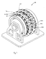
- Figure 1 shows a perspective view of an apparatus according to the present invention.
- the apparatus comprises two rotating drums 60, 70 which are essentially oriented symmetrically.
- the two drums 60, 70 apply discrete first and second web panels 40a, 40b to the left and right sides of the receiving web 1.
- a pair of incoming webs 40 are fed to the two sides of the apparatus and are cut in a nested pattern (see, for example, Figure 4), and the discrete first and second web panels 40a.
- 40b of the incoming webs are held on vacuum shells 80a, 80b which are arranged around the circumference of each of the rotating drums 60, 70.
- the receiving web 1, the incoming webs 40, and the cutting roll are not shown in Figure 1 to simplify this illustration.
- the drums 60, 70 are rotated about a main axis of the apparatus.
- the main axis is oriented horizontally, but this main axis need not necessarily be horizontal in all cases.
- Most preferably the two drums 60, 70 are rotated synchronously, at the same speed.
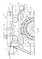
- alternate vacuum shells 80b are mounted on rotatable shafts 81 and are rotatable through 180° about an axis A which is radial with respect to the drum 60, 70.
- Each of the rotatable shafts 81 is connected, by means of a rack and pinion 82, 83, to a cam follower which runs around a shell turning cam 84.
- the shell turning cam 84 is shaped so that the rack and pinion 82, 83 operate to rotate the alternate vacuum shells 80b through 180° during a first part of the cycle, prior to transfer of the second web panels, 40b of the incoming web to the receiving web 1, and then return the vacuum shells 80b to their original orientation by rotating them back through minus 180° during a second part of the cycle after the transfer.
- a shell lifting cam acts to "lift” the vacuum shell 80b radially outwards from the drum 60, 70. This action helps to apply the second web panels 40b of the incoming web 40 to the receiving web 1 at a transfer step.
- the vacuum shells 80b are "withdrawn” radially inwards with respect to the drum 60, 70.
- the vacuum shells 80a i.e.
- those vacuum shells which have not been rotated during the first part of the cycle are "lifted” radially outwards from the drum 60, 70. This action helps to apply the first web panels 40a of the incoming web to the receiving web at a transfer step. Finally the vacuum shells 80a are “withdrawn” radially inwards with respect to the drum 60, 70, and the cycle is ready to repeat.
- the second web portion 40b is rotated through 180° in order to provide side panels, and preferably to provide alternately front and rear side panels for an absorbent article such as a diaper.
- the second web panel 40b is rotated through 90° in order to provide a component in the cross-machine direction, which is perpendicular to the first web panel 40a, preferably wherein the first and second web panels 40a, 40b are elastic.
- the cross-machine direction component may be a waist elastic for an absorbent article such as a diaper.
- the panels applied during the first part of the cycle of Figure 1 may be applied directly, without rotation, whilst the alternate panels which are subsequently applied in the second part of the cycle may be rotated (preferably through 180°) prior to application to the receiving web.
- Figure 3a shows a side elevation view of a continuous process for making an absorbent article 144.
- a continuous receiving web 1 is assembled from an absorbent pad element, or core 120, which is encased between a liquid-pervious topsheet 121 and a liquid impervious backsheet 123.
- the absorbent cores 120 are fed into the nip between a pair of laminating rolls 125, 126 at regularly spaced intervals by means of an infeed conveyor 127.
- the cores 120 are comprised of airfelt, within a cellulosic tissue envelope, to provide integrity to the core in use.
- the backsheet 123 is coated on its inner surface with beads or spirals of adhesive 128, for affixing the backsheet to the core 120.
- Continuous bands of elastic 130 are fed from metering rolls 131, 132 and 133 past a glue nozzle 135.
- the S-wrap arrangement of the rolls 131, 132 and 133 minimises deformation of the elastic band 130 and allows for accurate control of the speed of the elastic.
- the elastic bands are fed into the direction of transport, F, at a lower speed than the cores 120, the backsheet 123 and the topsheet 121, so that the elastic bands 130 are stretched.
- the web After passing through the combining nip, the web passes onto a perforated vacuum conveyor belt 137.
- a vacuum suction box 139 draws the web against the conveyor belt 137, to maintain a uniform tension in the receiving web 1.
- the web passes at a constant speed of transport to the infeed side 4 of the assembly 2 for periodically changing the speed of web.
- the receiving web 1 can be slowed down, or stopped and is contacted by the apparatus of the invention 38.
- the apparatus 38 comprises means for providing a web of material such as an elastic side panel, a waist cap or a strip of reinforcement material.
- the apparatus 38 can be located on the side of the topsheet 121 or on he side of the backsheet 123.
- the web 1 leaves the outfeed side 6 of the assembly 2 at the constant web speed.
- the speed of the receiving web portions located upstream and downstream from the assembly 2 along upstream trajectory 3 and downstream trajectory 5 is not affected by the change in speed of those parts of the receiving web 1 that are passing through the assembly 2.
- Figure 3b shows the assembly 2 for changing the speed of a flexible receiving web 1 of relatively low tear strength.
- flexible it is meant that the receiving web 1 can be transported along a curvilinear trajectory and will adapt its shape so as to conform to the trajectory.
- the receiving web 1 is formed of flexible material, such as paper, airfelt, plastic etc. and can be comprised of the core 120, the topsheet 121, the backsheet 123 or any combination thereof.
- the receiving web 1 is transported along the upstream trajectory 3 with a constant velocity of transport V 0 , in the machine direction F.
- the upstream trajectory 3 is formed by the length of the receiving web 1 which extends to the right of the first guide roller 9 in Figure 3b, and which is moving towards the infeed side 4 of the assembly. After passing through the assembly, the receiving web 1 exits at the outfeed side 6 and is transported at constant velocity V 0 along the downstream trajectory 5, which extends to the left of the guide roller 11.
- the upstream and downstream trajectories need not correspond to the machine direction, and can be formed by straight-line or curvilinear paths.
- the guide rollers 9 and 11 are rotationally connected to the frame 35.
- the guide rollers 9, 11 have a fixed position.
- the receiving web 1 is looped around an upstream and a downstream transport roller 13, 15 which are mounted on a sled 41.
- the sled 41 is cyclically translated along the frame 35, generally parallel to the machine direction F, by drive motor 36.
- An intermediate trajectory 7a, 7b, 7c of the receiving web 1 is located between the upstream guide roller 9 and the downstream guide roller 11, and comprises a first section 7a and a third section 7c, of variable length, located between the upstream guide roller 9 and the upstream transport roller 13 and the downstream transport roller 15 and the downstream guide roller 11 respectively.
- the second section 7c of the intermediate trajectory 7 is located between the transport rollers 13 and 15 and is of constant length.
- the web 1 When the part of the receiving web that is located along the second section 7b of the intermediate trajectory 7a, 7b, 7c, is stationary (or at least it is slower than the speed of the web speed V 0 ) relative to the frame 35, the web 1 is contacted by the apparatus 38 which is positionally stationary (or at least slower) with respect to the frame 35. After the apparatus 38 has interacted with the receiving web 1, the web is accelerated along the section 7b of the intermediate trajectory towards the outfeed side 6 of the assembly 2, and is supplied to the downstream trajectory 5 with web speed V 0 .
- the guide rollers 9, 11 and the transport rollers 13, 15 are driven by a drive member in the form of a closed loop 50 and pulleys 52, 53 and 54.
- the loop 50 is partly parallel to the intermediate trajectory 7a, 7b, 7c.
- the loop 50 is driven at a constant speed which is equal to the speed of transport V 0 , of the web 1 by a single drive motor 51.
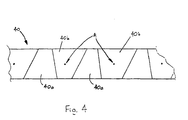
- Figure 4 shows a web 40 which has been cut into discrete portions 40a, 40b. Second portions 40b are subsequently rotated about their axis A.
- the first and second web panels 40a, 40b are applied, and preferably affixed, to the receiving web 1 using any conventional method such as by gluing with adhesives, such as melt adhesives, or use of self-adhesive components, or by use of ultrasonic welding, heat sealing or the like.
- the upstream and downstream transport rollers (13, 15) are periodically displaced relative to the guide rollers (9,11) around a transfer position preferably at a frequency of between 1 Hz and 100 Hz, more preferably between 1 Hz and 10 Hz.
Abstract
Description
- The invention relates to a process for manufacturing profiled disposable absorbent articles, and to an apparatus for performing the process, In a preferred embodiment the invention provides a process and apparatus for providing profiled side-panels, in particular elastic side-panels, without waste of the side-panel material. In particular, diapers or training pants may be made by the process of the invention having side "cut-outs" for better fit around the legs of the wearer, but the process may also be applied to feminine hygiene articles, adult incontinence articles, and other disposable absorbent articles.
- Disposable absorbent articles have become very popular in the market place today. Many of these articles include features such as side-panels that provide a variety of functions including improved containment characteristics and better, more comfortable fit.
- An overriding consideration in the construction of a disposable absorbent article is the cost of manufacturing the article, including the materials cost. The present invention provides methods for manufacturing side panels for absorbent articles with little or no wasted material. Thus, the side panels made by the process of the present invention can be provided at relatively lower cost than many of the side panels that are currently manufactured using techniques in which material is wasted. Processes which reduce or avoid material waste are disclosed in the following references.
- US-A-5 034 007, issued on July 23rd 1991, describes a method for cutting "nested ears" by making a periodic convex/concave cut lengthwise along a web. The two cut portions of the web are then separated and symmetrically arranged in the width direction with the straight edges on the inside and the convex/concave edge aligned on the outside. An alternative method of achieving the same result is disclosed in EP-A-0 396 050, published on 7th Nov. 1990. This discloses individually reversing all of the cut portions by turning them 180° about an axis lying in the plane of the web.
- WO96/24319, published 15th August 1996, discloses a method for manufacturing activated side-panels cutting in a "nested" pattern, and rotating all of the cut portions of the web through 180° about an axis lying in the plane of the web prior to attaching them to the diaper web (in particular this is illustrated in Figure 7).
- U.S. Patent 5,660,665 discloses an apparatus including a rotating base roll for applying at least one stretched strip of a first material to a base web comprising a second material and moving continuously in first direction. The discrete length strip is cut on the rotating roll from a continuous ribbon, is rotated on the base roll to a desired orientation and is stretched to a desired length. The apparatus includes the rotating roll feed apparatus for feeding the continuous ribbon to a circumferential engagement with the rotating roll, a cutter for cutting the discrete length strips from the continuous ribbon, at least one rotating extensible platen mounted on and rotating with the rotating roll and an applicator rotating in concert with the rotating base roll, for applying the cut, rotated and stretched strips to the base web.
- It is an object of the present invention to provide an alternative method of achieving the waste-saving advantages of "nested ears", and to provide an apparatus for use in the method.
- The invention provides a process and apparatus for the manufacture of disposable absorbent articles comprising the application of discrete web panels to a receiving web, wherein a plurality of first web panels and second web panels are cut from the same continuous web, and wherein the process comprises the steps of:
- cutting the continuous web to form at least a first web panel and a second web panel;
- rotating the second web panel; and
- applying the first web panel and the second web panel to the receiving web.
- The object of the invention is achieved by rotating the second web panel about an axis perpendicular to the plane of the second web panel.
-
- Figure 1 shows a perspective view of an apparatus for use in the process of the present invention;
- Figure 2 shows a side elevation view of the apparatus of Figure 1;
- Figure 3a shows a schematic side elevation view of a production line for the manufacture of an absorbent article;
- Figure 3b shows a schematic side elevation view of a part of a production line assembly as shown in Figure 3a comprising an apparatus of the present invention;
- Figure 4 shows a plan view of web panels after cutting, according to one embodiment of the process of the present invention.
-
- Figure 1 shows a perspective view of an apparatus according to the present invention. The apparatus comprises two
rotating drums drums second web panels incoming webs 40 are fed to the two sides of the apparatus and are cut in a nested pattern (see, for example, Figure 4), and the discrete first andsecond web panels 40a. 40b of the incoming webs are held on vacuum shells 80a, 80b which are arranged around the circumference of each of the rotatingdrums incoming webs 40, and the cutting roll are not shown in Figure 1 to simplify this illustration. - The
drums drums - In the embodiment shown in Figure 1, alternate vacuum shells 80b are mounted on rotatable shafts 81 and are rotatable through 180° about an axis A which is radial with respect to the
drum - In addition, during the first part of the cycle, a shell lifting cam (not shown in Figures 1 or 2), acts to "lift" the vacuum shell 80b radially outwards from the
drum second web panels 40b of theincoming web 40 to the receiving web 1 at a transfer step. During the second part of the cycle, after thecut web panels 40b of the incoming web have been transferred to the receiving web 1, the vacuum shells 80b are "withdrawn" radially inwards with respect to thedrum drum first web panels 40a of the incoming web to the receiving web at a transfer step. Finally the vacuum shells 80a are "withdrawn" radially inwards with respect to thedrum - In the embodiment of the invention shown in Figures 1 and 2 the
second web portion 40b is rotated through 180° in order to provide side panels, and preferably to provide alternately front and rear side panels for an absorbent article such as a diaper. In an alternative embodiment thesecond web panel 40b is rotated through 90° in order to provide a component in the cross-machine direction, which is perpendicular to thefirst web panel 40a, preferably wherein the first andsecond web panels - Figure 3a shows a side elevation view of a continuous process for making an
absorbent article 144. A continuous receiving web 1 is assembled from an absorbent pad element, orcore 120, which is encased between a liquid-pervious topsheet 121 and a liquidimpervious backsheet 123. Theabsorbent cores 120 are fed into the nip between a pair oflaminating rolls conveyor 127. In a preferred embodiment, thecores 120 are comprised of airfelt, within a cellulosic tissue envelope, to provide integrity to the core in use. Thebacksheet 123 is coated on its inner surface with beads or spirals ofadhesive 128, for affixing the backsheet to thecore 120. Continuous bands of elastic 130 are fed frommetering rolls glue nozzle 135. The S-wrap arrangement of therolls elastic band 130 and allows for accurate control of the speed of the elastic. The elastic bands are fed into the direction of transport, F, at a lower speed than thecores 120, thebacksheet 123 and thetopsheet 121, so that theelastic bands 130 are stretched. After passing through the combining nip, the web passes onto a perforatedvacuum conveyor belt 137. Avacuum suction box 139 draws the web against theconveyor belt 137, to maintain a uniform tension in the receiving web 1. The web passes at a constant speed of transport to the infeedside 4 of theassembly 2 for periodically changing the speed of web. In theassembly 2, the receiving web 1 can be slowed down, or stopped and is contacted by the apparatus of theinvention 38. Theapparatus 38 comprises means for providing a web of material such as an elastic side panel, a waist cap or a strip of reinforcement material. Theapparatus 38 can be located on the side of thetopsheet 121 or on he side of thebacksheet 123. The web 1 leaves theoutfeed side 6 of theassembly 2 at the constant web speed. The speed of the receiving web portions located upstream and downstream from theassembly 2 alongupstream trajectory 3 anddownstream trajectory 5 is not affected by the change in speed of those parts of the receiving web 1 that are passing through theassembly 2. - Figure 3b shows the
assembly 2 for changing the speed of a flexible receiving web 1 of relatively low tear strength. By flexible, it is meant that the receiving web 1 can be transported along a curvilinear trajectory and will adapt its shape so as to conform to the trajectory. The receiving web 1 is formed of flexible material, such as paper, airfelt, plastic etc. and can be comprised of thecore 120, thetopsheet 121, thebacksheet 123 or any combination thereof. - The receiving web 1 is transported along the
upstream trajectory 3 with a constant velocity of transport V0, in the machine direction F. Theupstream trajectory 3 is formed by the length of the receiving web 1 which extends to the right of thefirst guide roller 9 in Figure 3b, and which is moving towards theinfeed side 4 of the assembly. After passing through the assembly, the receiving web 1 exits at theoutfeed side 6 and is transported at constant velocity V0 along thedownstream trajectory 5, which extends to the left of theguide roller 11. The upstream and downstream trajectories need not correspond to the machine direction, and can be formed by straight-line or curvilinear paths. - The
guide rollers frame 35. Theguide rollers downstream transport roller sled 41. Thesled 41 is cyclically translated along theframe 35, generally parallel to the machine direction F, bydrive motor 36. - An
intermediate trajectory upstream guide roller 9 and thedownstream guide roller 11, and comprises afirst section 7a and athird section 7c, of variable length, located between theupstream guide roller 9 and theupstream transport roller 13 and thedownstream transport roller 15 and thedownstream guide roller 11 respectively. Thesecond section 7c of the intermediate trajectory 7 is located between thetransport rollers - Because of the symmetry of the
intermediate trajectory first section 7a, upon displacement of thesled 41 opposite to the machine direction F and away from theequilibrium position 39, is compensated by an equal decrease in length of thethird section 7c, and vice versa. As the length of thesecond section 7b is constant, the wholeintermediate trajectory sled 41 with respect to theframe 35. - When the part of the receiving web that is located along the
second section 7b of theintermediate trajectory frame 35, the web 1 is contacted by theapparatus 38 which is positionally stationary (or at least slower) with respect to theframe 35. After theapparatus 38 has interacted with the receiving web 1, the web is accelerated along thesection 7b of the intermediate trajectory towards theoutfeed side 6 of theassembly 2, and is supplied to thedownstream trajectory 5 with web speed V0. - The
guide rollers transport rollers closed loop 50 and pulleys 52, 53 and 54. Theloop 50 is partly parallel to theintermediate trajectory loop 50 is driven at a constant speed which is equal to the speed of transport V0, of the web 1 by asingle drive motor 51. By driving theguide rollers transport rollers - Figure 4 shows a
web 40 which has been cut intodiscrete portions Second portions 40b are subsequently rotated about their axis A. - The first and
second web panels - The upstream and downstream transport rollers (13, 15) are periodically displaced relative to the guide rollers (9,11) around a transfer position preferably at a frequency of between 1 Hz and 100 Hz, more preferably between 1 Hz and 10 Hz.
Claims (9)
- A process for the manufacture of disposable absorbent articles comprising the application of discrete web panels (40a, 40b) to a receiving web (1),
wherein a plurality of first web panels (40a) and second web panels (40b) are cut from the same continuous web (40), and wherein the process comprises the steps of :characterised in that a shell lifting cam acts to lift the vacuum shell (80a, 80b) radially outwards from said drum (60,70) to apply the web panels (40a, 40b) to the receiving web (1) at a transfer step.cutting the continuous web (40) to form at least a first web panel (40a) and a second web panel (40b); wherein said at least first web panel (40a) and said second web panel (40b) are held on vacuum shells (80a,80b), said vacuum shells (80a,80b) being arranged around the circumference of drums (60,70), said drums (60,70) being rotated about a main axis;rotating the second web panel (40b); about an axis (A) perpendicular to the plane of the second web panel (40)) andapplying the first web panel (40a) and the second web panel (40b) to the receiving web (1); - A process according to claim 1 wherein the second web panel (40b) is rotated through 180° in order to provide side panels, preferably to provide alternately front and rear side panels.
- A process according to claim 1 wherein the second web panel (40b) is rotated though 90° in order to provide a component in the cross-machine direction, which is perpendicular to the first web panel (40a), preferably wherein the first and second web panels (40a. 40b) are elastic.
- A process according to any of claims 1 to 3 wherein the first and second web panels (40a, 40b) are applied to the receiving web (1) at substantially matched speeds.
- A process according to claim 4 wherein the receiving web (1) is fed relative to a stationary frame (35) along an upstream trajectory (3), a downstream trajectory (5), and an intermediate trajectory (7a, 7b, 7c) comprised between the upstream trajectory (3) and the downstream trajectory (5), the web (1) having along the upstream trajectory (3) and along the downstream trajectory (5) a substantially constant speed of transport, wherein the receiving web (1) runs along an upstream and a downstream guide roller (9, 11) that are translationally stationary relative to the frame (35) and along an upstream and downstream transport roller (13, 15) that are periodically displaced relative to the guide rollers (9, 11) around a transfer position, and wherein the discrete web panels (40a, 40b) are applied to the receiving web (1) when it is at the transfer position.
- A process according to claim 5 wherein the periodic displacement of the transport rollers (13, 15) around the transfer position occurs at a frequency of between 1 Hz and 100 Hz, preferably between 1 Hz and 10 Hz.
- A process according to any of the previous claims wherein the receiving web (1) comprises a liquid-pervious topsheet (121), a liquid impervious backsheet (123), and an absorbent core (120).
- An apparatus (38) for the manufacture of disposable absorbent articles wherein the apparatus has means for applying discrete web panels (40a, 40b) to a receiving web (1), wherein the apparatus comprisescharacterised in that the apparatus further comprises a shell lifting cam able to lift the vacuum shell (80a,80b) radially outwards from said drum (60,70) to apply the web panels (40a,40b) to the receiving web (1) at a transfer step.a means for cutting adjacent first web panel (40a) and second web panel (40b) from the same continuous web (40) to form at least the first web panel (40a) and the second web panel (40b);a means for rotating the second web panel (40b); and two rotating drums (60,70) for applying the first web panel (40a) and the second web panel (40b) to the receiving web (1); and vacuum shells (80a, 80b) which are arranged around the circumference of each of the rotating drums (60, 70), wherein at least some of the vacuum shells (80b) are rotatable about an axis (A) perpendicular to the plane of the second web panel (40b) whereby the second web panel (40b) is rotated about an axis (9A) perpendicular to the plane of the second web panel (40b)
- The apparatus according to claim 8, wherein the vacuum shells (80b) are rotatable by means of rach and pinion (82,83).
Priority Applications (1)
| Application Number | Priority Date | Filing Date | Title |
|---|---|---|---|
| EP00944871A EP1189564B1 (en) | 1999-06-25 | 2000-06-23 | Process for manufacturing disposable absorbent articles, and an apparatus for performing the process |
Applications Claiming Priority (4)
| Application Number | Priority Date | Filing Date | Title |
|---|---|---|---|
| EP99112228 | 1999-06-25 | ||
| EP99112228A EP1062928A1 (en) | 1999-06-25 | 1999-06-25 | Process for manufacturing disposable absorbent articles, and an apparatus for performing the process |
| PCT/US2000/017489 WO2001000122A1 (en) | 1999-06-25 | 2000-06-23 | Process for manufacturing disposable absorbent articles, and an apparatus for performing the process |
| EP00944871A EP1189564B1 (en) | 1999-06-25 | 2000-06-23 | Process for manufacturing disposable absorbent articles, and an apparatus for performing the process |
Publications (2)
| Publication Number | Publication Date |
|---|---|
| EP1189564A1 EP1189564A1 (en) | 2002-03-27 |
| EP1189564B1 true EP1189564B1 (en) | 2005-03-23 |
Family
ID=8238421
Family Applications (2)
| Application Number | Title | Priority Date | Filing Date |
|---|---|---|---|
| EP99112228A Withdrawn EP1062928A1 (en) | 1999-06-25 | 1999-06-25 | Process for manufacturing disposable absorbent articles, and an apparatus for performing the process |
| EP00944871A Expired - Lifetime EP1189564B1 (en) | 1999-06-25 | 2000-06-23 | Process for manufacturing disposable absorbent articles, and an apparatus for performing the process |
Family Applications Before (1)
| Application Number | Title | Priority Date | Filing Date |
|---|---|---|---|
| EP99112228A Withdrawn EP1062928A1 (en) | 1999-06-25 | 1999-06-25 | Process for manufacturing disposable absorbent articles, and an apparatus for performing the process |
Country Status (8)
| Country | Link |
|---|---|
| EP (2) | EP1062928A1 (en) |
| JP (1) | JP4583683B2 (en) |
| AT (1) | ATE291403T1 (en) |
| AU (1) | AU5890200A (en) |
| CA (1) | CA2375955A1 (en) |
| DE (1) | DE60018929T2 (en) |
| MX (1) | MXPA01013373A (en) |
| WO (1) | WO2001000122A1 (en) |
Cited By (2)
| Publication number | Priority date | Publication date | Assignee | Title |
|---|---|---|---|---|
| US9289329B1 (en) | 2013-12-05 | 2016-03-22 | Curt G. Joa, Inc. | Method for producing pant type diapers |
| US9433538B2 (en) | 2006-05-18 | 2016-09-06 | Curt G. Joa, Inc. | Methods and apparatus for application of nested zero waste ear to traveling web and formation of articles using a dual cut slip unit |
Families Citing this family (11)
| Publication number | Priority date | Publication date | Assignee | Title |
|---|---|---|---|---|
| DE19937729A1 (en) * | 1999-08-10 | 2001-02-15 | Lurgi Zimmer Ag | High tenacity polyester threads and process for their manufacture |
| US6702917B1 (en) | 2002-08-30 | 2004-03-09 | Kimberly-Clark Worldwide, Inc. | Cross-machine-direction nested absorbent pads with minimal waste geometries |
| US7070672B2 (en) | 2004-02-24 | 2006-07-04 | Kimberly-Clark Worldwide, Inc. | Process for making a feminine sanitary napkin or other absorbent article having place and cut wings |
| US7163529B2 (en) | 2004-12-15 | 2007-01-16 | Kimberly-Clark Worldwide, Inc. | Absorbent article having disposal wings with odor absorbency |
| JP4522342B2 (en) * | 2005-08-11 | 2010-08-11 | 花王株式会社 | Method and apparatus for manufacturing absorbent article |
| US9622918B2 (en) | 2006-05-18 | 2017-04-18 | Curt G. Joe, Inc. | Methods and apparatus for application of nested zero waste ear to traveling web |
| US10456302B2 (en) | 2006-05-18 | 2019-10-29 | Curt G. Joa, Inc. | Methods and apparatus for application of nested zero waste ear to traveling web |
| US8016972B2 (en) | 2007-05-09 | 2011-09-13 | Curt G. Joa, Inc. | Methods and apparatus for application of nested zero waste ear to traveling web |
| ITBO20120655A1 (en) * | 2012-12-03 | 2014-06-04 | Gdm Spa | MACHINE FOR THE CONSTRUCTION OF HYGIENIC ABSORBENT ITEMS. |
| CN103479480B (en) * | 2013-08-29 | 2015-05-20 | 安庆市恒昌机械制造有限责任公司 | On-line waistline cutting and rotating pitch-variable assembly for disposable sanitary product |
| CN108481433B (en) * | 2018-04-20 | 2024-04-12 | 安庆市恒昌机械制造有限责任公司 | Sheet material transfer component and process |
Family Cites Families (12)
| Publication number | Priority date | Publication date | Assignee | Title |
|---|---|---|---|---|
| JPH0780610B2 (en) * | 1987-08-04 | 1995-08-30 | 株式会社瑞光 | Method of manufacturing disposable diapers |
| CA1298818C (en) * | 1987-12-16 | 1992-04-14 | Paul Theodore Van Gompel | Method and apparatus for making a disposable incontinence garment or training pant |
| JPH0751143B2 (en) * | 1988-04-19 | 1995-06-05 | 株式会社瑞光 | How to make and attach elastic tape |
| JP2622414B2 (en) * | 1989-04-29 | 1997-06-18 | ユニ・チャーム株式会社 | Method of manufacturing component for wearing article |
| US5034007A (en) * | 1990-02-23 | 1991-07-23 | Uni-Charm Corporation | Manufacturing method for disposable clothing items |
| JPH04261655A (en) * | 1990-12-31 | 1992-09-17 | Zuikou:Kk | Manufacture of paper diaper |
| US5396978A (en) * | 1993-08-09 | 1995-03-14 | The Procter & Gamble Company | Apparatus for attaching elastic at an angle |
| ES2111696T3 (en) * | 1993-11-04 | 1998-03-16 | Procter & Gamble | METHOD TO MANUFACTURE AN ABSORBENT ARTICLE AND APPARATUS TO CARRY OUT SUCH METHOD. |
| JPH08661A (en) * | 1994-06-24 | 1996-01-09 | Honshu Paper Co Ltd | Surface material for diaper having pocket structure and its manufacture and diaper |
| US5580411A (en) * | 1995-02-10 | 1996-12-03 | The Procter & Gamble Company | Zero scrap method for manufacturing side panels for absorbent articles |
| JP3131130B2 (en) * | 1995-09-29 | 2001-01-31 | ユニ・チャーム株式会社 | Manufacturing method of wearing article constituent member |
| US5660665A (en) * | 1995-12-15 | 1997-08-26 | Kimberly-Clark Corporation | Rotating transfer roll with rotating extensible platen |
-
1999
- 1999-06-25 EP EP99112228A patent/EP1062928A1/en not_active Withdrawn
-
2000
- 2000-06-23 CA CA002375955A patent/CA2375955A1/en not_active Abandoned
- 2000-06-23 AT AT00944871T patent/ATE291403T1/en not_active IP Right Cessation
- 2000-06-23 WO PCT/US2000/017489 patent/WO2001000122A1/en active IP Right Grant
- 2000-06-23 DE DE60018929T patent/DE60018929T2/en not_active Expired - Lifetime
- 2000-06-23 AU AU58902/00A patent/AU5890200A/en not_active Abandoned
- 2000-06-23 EP EP00944871A patent/EP1189564B1/en not_active Expired - Lifetime
- 2000-06-23 MX MXPA01013373A patent/MXPA01013373A/en unknown
- 2000-06-23 JP JP2001505839A patent/JP4583683B2/en not_active Expired - Fee Related
Cited By (2)
| Publication number | Priority date | Publication date | Assignee | Title |
|---|---|---|---|---|
| US9433538B2 (en) | 2006-05-18 | 2016-09-06 | Curt G. Joa, Inc. | Methods and apparatus for application of nested zero waste ear to traveling web and formation of articles using a dual cut slip unit |
| US9289329B1 (en) | 2013-12-05 | 2016-03-22 | Curt G. Joa, Inc. | Method for producing pant type diapers |
Also Published As
| Publication number | Publication date |
|---|---|
| WO2001000122A1 (en) | 2001-01-04 |
| ATE291403T1 (en) | 2005-04-15 |
| JP4583683B2 (en) | 2010-11-17 |
| JP2003503108A (en) | 2003-01-28 |
| AU5890200A (en) | 2001-01-31 |
| EP1189564A1 (en) | 2002-03-27 |
| DE60018929T2 (en) | 2006-03-30 |
| EP1062928A1 (en) | 2000-12-27 |
| CA2375955A1 (en) | 2001-01-04 |
| DE60018929D1 (en) | 2005-04-28 |
| MXPA01013373A (en) | 2002-07-02 |
Similar Documents
| Publication | Publication Date | Title |
|---|---|---|
| US6730189B1 (en) | Process for manufacturing disposable absorbent articles, and an apparatus for performing the process | |
| US11147720B2 (en) | Elastic composite for having cross-directional elasticity and a system and method for making the elastic composite | |
| EP1189564B1 (en) | Process for manufacturing disposable absorbent articles, and an apparatus for performing the process | |
| US4776911A (en) | Elasticized unit, apparatus for making the elasticized unit, garments incorporating the units, and method for making the garment | |
| US4293367A (en) | Apparatus for effecting securement of a transversely moved elastic ribbon to a moving web | |
| CN115154047B (en) | System and method for producing elastic composite materials | |
| JP2622414B2 (en) | Method of manufacturing component for wearing article | |
| KR20020034097A (en) | Assembly and method for rotating and placing strip of material on a substrate | |
| EP1189565B1 (en) | Process for manufacturing disposable absorbent cores, and an apparatus for performing the process | |
| EP3638177B1 (en) | Methods for transferring discrete articles | |
| US6736923B1 (en) | Process for manufacturing disposable absorbent cores, and an apparatus for performing the process | |
| EP0443244A1 (en) | Method and apparatus for applying an elastic waistband to a disposable diaper | |
| TWI556800B (en) | Apparatus for building | |
| CA2955743A1 (en) | Slip-cut operation with static electric holding force and ultrasonic bonding apparatus | |
| JP2001346825A (en) | Method and apparatus for manufacturing diaper and diaper | |
| JPH06209968A (en) | Installation of waist band of paper diaper | |
| AU2015203499B2 (en) | An elastic composite having cross-directional elasticity and a system and method for making the elastic composite | |
| EP1139948B1 (en) | Apparatus and process for applying discrete portions of a web material onto a receiving web | |
| MXPA01007123A (en) | Apparatus and process for applying discrete portions of a web material onto a receiving web | |
| MXPA01000729A (en) | Apparatus for transporting a continuous web, and for manipulating the web |
Legal Events
| Date | Code | Title | Description |
|---|---|---|---|
| PUAI | Public reference made under article 153(3) epc to a published international application that has entered the european phase |
Free format text: ORIGINAL CODE: 0009012 |
|
| 17P | Request for examination filed |
Effective date: 20011221 |
|
| AK | Designated contracting states |
Kind code of ref document: A1 Designated state(s): AT BE CH CY DE DK ES FI FR GB GR IE IT LI LU MC NL PT SE |
|
| AX | Request for extension of the european patent |
Free format text: AL;LT;LV;MK;RO;SI |
|
| 17Q | First examination report despatched |
Effective date: 20040102 |
|
| GRAP | Despatch of communication of intention to grant a patent |
Free format text: ORIGINAL CODE: EPIDOSNIGR1 |
|
| GRAS | Grant fee paid |
Free format text: ORIGINAL CODE: EPIDOSNIGR3 |
|
| GRAA | (expected) grant |
Free format text: ORIGINAL CODE: 0009210 |
|
| AK | Designated contracting states |
Kind code of ref document: B1 Designated state(s): AT BE CH CY DE DK ES FI FR GB GR IE IT LI LU MC NL PT SE |
|
| PG25 | Lapsed in a contracting state [announced via postgrant information from national office to epo] |
Ref country code: IT Free format text: LAPSE BECAUSE OF FAILURE TO SUBMIT A TRANSLATION OF THE DESCRIPTION OR TO PAY THE FEE WITHIN THE PRESCRIBED TIME-LIMIT;WARNING: LAPSES OF ITALIAN PATENTS WITH EFFECTIVE DATE BEFORE 2007 MAY HAVE OCCURRED AT ANY TIME BEFORE 2007. THE CORRECT EFFECTIVE DATE MAY BE DIFFERENT FROM THE ONE RECORDED. Effective date: 20050323 Ref country code: FI Free format text: LAPSE BECAUSE OF FAILURE TO SUBMIT A TRANSLATION OF THE DESCRIPTION OR TO PAY THE FEE WITHIN THE PRESCRIBED TIME-LIMIT Effective date: 20050323 Ref country code: LI Free format text: LAPSE BECAUSE OF FAILURE TO SUBMIT A TRANSLATION OF THE DESCRIPTION OR TO PAY THE FEE WITHIN THE PRESCRIBED TIME-LIMIT Effective date: 20050323 Ref country code: NL Free format text: LAPSE BECAUSE OF FAILURE TO SUBMIT A TRANSLATION OF THE DESCRIPTION OR TO PAY THE FEE WITHIN THE PRESCRIBED TIME-LIMIT Effective date: 20050323 Ref country code: CH Free format text: LAPSE BECAUSE OF FAILURE TO SUBMIT A TRANSLATION OF THE DESCRIPTION OR TO PAY THE FEE WITHIN THE PRESCRIBED TIME-LIMIT Effective date: 20050323 Ref country code: AT Free format text: LAPSE BECAUSE OF FAILURE TO SUBMIT A TRANSLATION OF THE DESCRIPTION OR TO PAY THE FEE WITHIN THE PRESCRIBED TIME-LIMIT Effective date: 20050323 Ref country code: BE Free format text: LAPSE BECAUSE OF FAILURE TO SUBMIT A TRANSLATION OF THE DESCRIPTION OR TO PAY THE FEE WITHIN THE PRESCRIBED TIME-LIMIT Effective date: 20050323 |
|
| REG | Reference to a national code |
Ref country code: GB Ref legal event code: FG4D |
|
| REG | Reference to a national code |
Ref country code: CH Ref legal event code: EP |
|
| REG | Reference to a national code |
Ref country code: IE Ref legal event code: FG4D |
|
| REF | Corresponds to: |
Ref document number: 60018929 Country of ref document: DE Date of ref document: 20050428 Kind code of ref document: P |
|
| PG25 | Lapsed in a contracting state [announced via postgrant information from national office to epo] |
Ref country code: LU Free format text: LAPSE BECAUSE OF NON-PAYMENT OF DUE FEES Effective date: 20050623 Ref country code: DK Free format text: LAPSE BECAUSE OF FAILURE TO SUBMIT A TRANSLATION OF THE DESCRIPTION OR TO PAY THE FEE WITHIN THE PRESCRIBED TIME-LIMIT Effective date: 20050623 Ref country code: IE Free format text: LAPSE BECAUSE OF NON-PAYMENT OF DUE FEES Effective date: 20050623 Ref country code: CY Free format text: LAPSE BECAUSE OF FAILURE TO SUBMIT A TRANSLATION OF THE DESCRIPTION OR TO PAY THE FEE WITHIN THE PRESCRIBED TIME-LIMIT Effective date: 20050623 Ref country code: GR Free format text: LAPSE BECAUSE OF FAILURE TO SUBMIT A TRANSLATION OF THE DESCRIPTION OR TO PAY THE FEE WITHIN THE PRESCRIBED TIME-LIMIT Effective date: 20050623 |
|
| PG25 | Lapsed in a contracting state [announced via postgrant information from national office to epo] |
Ref country code: MC Free format text: LAPSE BECAUSE OF NON-PAYMENT OF DUE FEES Effective date: 20050630 |
|
| PG25 | Lapsed in a contracting state [announced via postgrant information from national office to epo] |
Ref country code: ES Free format text: LAPSE BECAUSE OF FAILURE TO SUBMIT A TRANSLATION OF THE DESCRIPTION OR TO PAY THE FEE WITHIN THE PRESCRIBED TIME-LIMIT Effective date: 20050704 |
|
| NLV1 | Nl: lapsed or annulled due to failure to fulfill the requirements of art. 29p and 29m of the patents act | ||
| PG25 | Lapsed in a contracting state [announced via postgrant information from national office to epo] |
Ref country code: PT Free format text: LAPSE BECAUSE OF FAILURE TO SUBMIT A TRANSLATION OF THE DESCRIPTION OR TO PAY THE FEE WITHIN THE PRESCRIBED TIME-LIMIT Effective date: 20050907 |
|
| REG | Reference to a national code |
Ref country code: CH Ref legal event code: PL |
|
| PLBE | No opposition filed within time limit |
Free format text: ORIGINAL CODE: 0009261 |
|
| STAA | Information on the status of an ep patent application or granted ep patent |
Free format text: STATUS: NO OPPOSITION FILED WITHIN TIME LIMIT |
|
| 26N | No opposition filed |
Effective date: 20051227 |
|
| REG | Reference to a national code |
Ref country code: IE Ref legal event code: MM4A |
|
| EN | Fr: translation not filed | ||
| PG25 | Lapsed in a contracting state [announced via postgrant information from national office to epo] |
Ref country code: SE Free format text: LAPSE BECAUSE OF FAILURE TO SUBMIT A TRANSLATION OF THE DESCRIPTION OR TO PAY THE FEE WITHIN THE PRESCRIBED TIME-LIMIT Effective date: 20050623 |
|
| PG25 | Lapsed in a contracting state [announced via postgrant information from national office to epo] |
Ref country code: FR Free format text: LAPSE BECAUSE OF NON-PAYMENT OF DUE FEES Effective date: 20050630 |
|
| PG25 | Lapsed in a contracting state [announced via postgrant information from national office to epo] |
Ref country code: FR Free format text: LAPSE BECAUSE OF NON-PAYMENT OF DUE FEES Effective date: 20050323 |
|
| PGFP | Annual fee paid to national office [announced via postgrant information from national office to epo] |
Ref country code: GB Payment date: 20150526 Year of fee payment: 16 |
|
| PGFP | Annual fee paid to national office [announced via postgrant information from national office to epo] |
Ref country code: DE Payment date: 20150630 Year of fee payment: 16 |
|
| REG | Reference to a national code |
Ref country code: DE Ref legal event code: R119 Ref document number: 60018929 Country of ref document: DE |
|
| GBPC | Gb: european patent ceased through non-payment of renewal fee |
Effective date: 20160623 |
|
| PG25 | Lapsed in a contracting state [announced via postgrant information from national office to epo] |
Ref country code: DE Free format text: LAPSE BECAUSE OF NON-PAYMENT OF DUE FEES Effective date: 20170103 |
|
| PG25 | Lapsed in a contracting state [announced via postgrant information from national office to epo] |
Ref country code: GB Free format text: LAPSE BECAUSE OF NON-PAYMENT OF DUE FEES Effective date: 20160623 |