EP1193200A1 - Apparatus for automatic splicing of feeding rolls with thin webs - Google Patents
Apparatus for automatic splicing of feeding rolls with thin webs Download PDFInfo
- Publication number
- EP1193200A1 EP1193200A1 EP01402345A EP01402345A EP1193200A1 EP 1193200 A1 EP1193200 A1 EP 1193200A1 EP 01402345 A EP01402345 A EP 01402345A EP 01402345 A EP01402345 A EP 01402345A EP 1193200 A1 EP1193200 A1 EP 1193200A1
- Authority
- EP
- European Patent Office
- Prior art keywords
- move
- heads
- thin strips
- strip
- supply
- Prior art date
- Legal status (The legal status is an assumption and is not a legal conclusion. Google has not performed a legal analysis and makes no representation as to the accuracy of the status listed.)
- Granted
Links
Images


Classifications
-
- B—PERFORMING OPERATIONS; TRANSPORTING
- B65—CONVEYING; PACKING; STORING; HANDLING THIN OR FILAMENTARY MATERIAL
- B65H—HANDLING THIN OR FILAMENTARY MATERIAL, e.g. SHEETS, WEBS, CABLES
- B65H19/00—Changing the web roll
- B65H19/10—Changing the web roll in unwinding mechanisms or in connection with unwinding operations
- B65H19/18—Attaching, e.g. pasting, the replacement web to the expiring web
- B65H19/1857—Support arrangement of web rolls
- B65H19/1873—Support arrangement of web rolls with two stationary roll supports carrying alternately the replacement and the expiring roll
-
- B—PERFORMING OPERATIONS; TRANSPORTING
- B65—CONVEYING; PACKING; STORING; HANDLING THIN OR FILAMENTARY MATERIAL
- B65H—HANDLING THIN OR FILAMENTARY MATERIAL, e.g. SHEETS, WEBS, CABLES
- B65H19/00—Changing the web roll
- B65H19/10—Changing the web roll in unwinding mechanisms or in connection with unwinding operations
- B65H19/18—Attaching, e.g. pasting, the replacement web to the expiring web
- B65H19/1842—Attaching, e.g. pasting, the replacement web to the expiring web standing splicing, i.e. the expiring web being stationary during splicing contact
- B65H19/1852—Attaching, e.g. pasting, the replacement web to the expiring web standing splicing, i.e. the expiring web being stationary during splicing contact taking place at a distance from the replacement roll
-
- B—PERFORMING OPERATIONS; TRANSPORTING
- B65—CONVEYING; PACKING; STORING; HANDLING THIN OR FILAMENTARY MATERIAL
- B65H—HANDLING THIN OR FILAMENTARY MATERIAL, e.g. SHEETS, WEBS, CABLES
- B65H2301/00—Handling processes for sheets or webs
- B65H2301/40—Type of handling process
- B65H2301/41—Winding, unwinding
- B65H2301/413—Supporting web roll
- B65H2301/4134—Both ends type arrangement
- B65H2301/41346—Both ends type arrangement separate elements engaging each end of the roll (e.g. chuck)
-
- B—PERFORMING OPERATIONS; TRANSPORTING
- B65—CONVEYING; PACKING; STORING; HANDLING THIN OR FILAMENTARY MATERIAL
- B65H—HANDLING THIN OR FILAMENTARY MATERIAL, e.g. SHEETS, WEBS, CABLES
- B65H2301/00—Handling processes for sheets or webs
- B65H2301/40—Type of handling process
- B65H2301/41—Winding, unwinding
- B65H2301/417—Handling or changing web rolls
- B65H2301/418—Changing web roll
- B65H2301/4185—Core or mandrel discharge or removal, also organisation of core removal
-
- B—PERFORMING OPERATIONS; TRANSPORTING
- B65—CONVEYING; PACKING; STORING; HANDLING THIN OR FILAMENTARY MATERIAL
- B65H—HANDLING THIN OR FILAMENTARY MATERIAL, e.g. SHEETS, WEBS, CABLES
- B65H2301/00—Handling processes for sheets or webs
- B65H2301/40—Type of handling process
- B65H2301/46—Splicing
- B65H2301/461—Processing webs in splicing process
- B65H2301/4615—Processing webs in splicing process after splicing
- B65H2301/4617—Processing webs in splicing process after splicing cutting webs in splicing process
- B65H2301/46174—Processing webs in splicing process after splicing cutting webs in splicing process cutting both spliced webs separately
-
- B—PERFORMING OPERATIONS; TRANSPORTING
- B65—CONVEYING; PACKING; STORING; HANDLING THIN OR FILAMENTARY MATERIAL
- B65H—HANDLING THIN OR FILAMENTARY MATERIAL, e.g. SHEETS, WEBS, CABLES
- B65H2301/00—Handling processes for sheets or webs
- B65H2301/40—Type of handling process
- B65H2301/46—Splicing
- B65H2301/462—Form of splice
- B65H2301/4622—Abutting article or web portions, i.e. edge to edge
-
- B—PERFORMING OPERATIONS; TRANSPORTING
- B65—CONVEYING; PACKING; STORING; HANDLING THIN OR FILAMENTARY MATERIAL
- B65H—HANDLING THIN OR FILAMENTARY MATERIAL, e.g. SHEETS, WEBS, CABLES
- B65H2301/00—Handling processes for sheets or webs
- B65H2301/40—Type of handling process
- B65H2301/46—Splicing
- B65H2301/463—Splicing splicing means, i.e. means by which a web end is bound to another web end
- B65H2301/4631—Adhesive tape
-
- B—PERFORMING OPERATIONS; TRANSPORTING
- B65—CONVEYING; PACKING; STORING; HANDLING THIN OR FILAMENTARY MATERIAL
- B65H—HANDLING THIN OR FILAMENTARY MATERIAL, e.g. SHEETS, WEBS, CABLES
- B65H2301/00—Handling processes for sheets or webs
- B65H2301/40—Type of handling process
- B65H2301/46—Splicing
- B65H2301/464—Splicing effecting splice
- B65H2301/46412—Splicing effecting splice by element moving in a direction perpendicular to the running direction of the web
-
- B—PERFORMING OPERATIONS; TRANSPORTING
- B65—CONVEYING; PACKING; STORING; HANDLING THIN OR FILAMENTARY MATERIAL
- B65H—HANDLING THIN OR FILAMENTARY MATERIAL, e.g. SHEETS, WEBS, CABLES
- B65H2408/00—Specific machines
- B65H2408/20—Specific machines for handling web(s)
- B65H2408/22—Splicing machines
- B65H2408/221—Splicing machines features of splicing unit
- B65H2408/2211—Splicing machines features of splicing unit splicing unit located above several web rolls arranged parallel to each other
-
- B—PERFORMING OPERATIONS; TRANSPORTING
- B65—CONVEYING; PACKING; STORING; HANDLING THIN OR FILAMENTARY MATERIAL
- B65H—HANDLING THIN OR FILAMENTARY MATERIAL, e.g. SHEETS, WEBS, CABLES
- B65H2701/00—Handled material; Storage means
- B65H2701/10—Handled articles or webs
- B65H2701/17—Nature of material
- B65H2701/176—Cardboard
- B65H2701/1762—Corrugated
Definitions
- the present invention relates to an automatic device thin strip connection for systems with continuous feed in which the tape coming from the supply coil, when it ends, is joined to that of a new coil so that the process can be to pursue.
- the devices performing this function include two reel holders and tape joining mechanisms that can be put in the working and handling position to prepare the connection of the coil strip which is waiting at the power strip at the appropriate time.
- the present invention provides a device for connection which eliminates these drawbacks thanks to its structure and its operation which differ from those of the devices conventional.
- the device of the invention comprises two reel holders, which are mounted so that they can be moved vertically thanks to transporters, and two heads which can be move horizontally on their own to move from a position where they are close to each other to a position where they are separated and at the location respective reel holders however above these the latter are arranged with other elements which may be move horizontally from a position where they are above the spool holders to a position outside the structure.
- the heads are mounted on a guide device based on a supporting structure and have the means individual displacement and blocking for their temporary immobilization; each head has a group of which the role is to join the two bands end to end using pressure and cutting tools.
- the reel holders are mounted on support guides vertical along which they can move; each of these reel holders have two arms which can be brought closer or separate and are provided with means ensuring the fixing rotating mandrels of the coils to be supported, these means being in turn provided with brakes so as to control the rotation of the coil and expulsion means allowing release the chuck when it needs to be removed.
- Elements that can be placed above the spool holders are mounted on guides that support them and have their own means of actuation; these items include hook-shaped hanging arms that can remove the empty spool mandrel to deposit it outside the structure via a fixed ramp.
- This set constitutes a connection device which automatically joins the end of the reel strip which empty at the start of a new strip so as to continue food; this device also makes it possible to prepare the new strip while the supply of the first strip is continues without the operator having to make any effort to move the heads since the movements of the latter are controlled by the motors in each position.
- reel holders move automatically between the lower and upper positions which allows place below the coil that powers the machine, before let it empty, another full while the elements displaceable automatically remove the mandrel from the top empty coils leaving the operator the only care put the new strip on the corresponding head once the full spool is installed on the released spool holder.
- Figure 1 shows a perspective view of the device recommended connection.
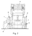
- Figure 2 is a front view of one end of the connection device.
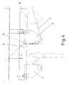
- Figure 3 is a side view of the device connection.
- Figure 4 is a schematic enlarged detail view of the position of the heads of the connection device at the time of the preparation of the new band which will remain in waiting.
- Figure 5 is a schematic enlarged detail view of the position of the heads of the connection device when they are close together and ready for the union of the bands.
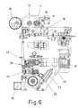
- Figure 6 is an enlarged side view of one of the heads of the connecting device.
- Figure 7 is a side view of the two heads of the connection device when separated.
- Figure 8 is a side view of the two heads of the connection device when they are brought together the other .
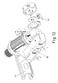
- Figure 9 is an exploded perspective view of the entire vertical guidance system of one of the reel holders of the connection device.
- Figure 10 is an exploded perspective view of the axis with the arm guides of one of the spool holders.
- Figure 11 is an exploded perspective view of the gripping mechanism of the spool mandrel which is on the arms of the spools of the connection device.
- FIG. 12 is a perspective view of one of the arms of the spool holder of the connection device with a view exploded expulsion mechanism which detaches the mandrel from the coils.
- FIG. 13 is a perspective view of one of the arms of the spool holder of the connection device with a view burst of the braking mechanism which controls the rotation of coils.
- Figure 14 is a perspective view of the structure of mounting of one of the movable elements above spool holders of the connection device.
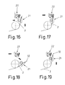
- Figures 15 to 22 are detailed views of the positions successive connection tools during the sequence gluing the final end of the first strip at the start news.
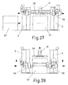
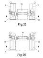
- Figures 23 to 28 show the successive positions the reel loading and replacement sequence on one of the spool holders of the connection device.
- the object of the invention consists of a device for connection which allows to join thin strips (1) and (2) and thus ensuring continuous feeding in the processes where it applies.
- connection device includes two reel holders (3) and (4) which can move vertically and are mounted on load-bearing structures (5) located at the ends of the entire connection device.
- reel holders (3) and (4) are other horizontal structures (9) and (10) along which moving hanging elements (11) and (12) having the form hooks.
- Each of the two heads (6) and (7) is equipped with a motor (17) which allows it to move independently on the structure (8) (cf. fig. 6); these heads (6) and (7) are also equipped with various means (19) which ensure their immobility (6) and (7) when they are close together each other in a central position.
- These heads (6) and (7) also include groups (20) allowing to join the bands (1) and (2) which must be connected.
- These groups (20) are identical for both heads (6) and (7) and each of them comprises two sets independent (21) and (22) of which the first (21) can switch one cylinder (23) while the other can be pushed forward by means of another cylinder (24).
- the tiltable assembly (21) has a fixed front element and an element which is pushed towards it by a cylinder (25) while in the pusher assembly (22) is housed, in a front groove, a retractable knife that can move longitudinally.
- the reel holders (3) and (4) are mounted on guides (26) by means of a carriage (27) which moves by sliding along these guides (26) (cf. fig. 9); the movement of the carriage (27) is caused by a mechanism transmission included in the guides (26) and actuated by motors (28) as can be seen in Figures 2 and 3. In this way each of the reel holders (3) and (4) can be move independently either vertically or along load-bearing structures (5).
- the assembly (21) is then tilted upwards and, simultaneously, the movable element of this assembly (21) so that the strip (2) is pinched between this mobile element and the fixed element opposite it (cf. Fig. 16).
- the assembly (22) of this group (20) then moves towards the front holding the end of the strip (2) captive in the pinching against the fixed element of the assembly (21) as the shows figure (17); the knife of the assembly (22) cuts then the end of the strip (2) along a straight line perfect.
- the assembly (21) is then tilted again towards the top (see fig. 19) and the assembly (22) moves a new times forward until pressing against the fixed element of the assembly (21) the strip (2) while, simultaneously, the entire head (7) moves towards the head (6) to position itself against the latter (cf. fig. 20).
- the strip (2) is glued to the strip (1) by the adhesive strip (32) and the knife of the assembly (22) of the group (20) of the head (6) cuts the strip (1) so that its edge corresponds to the free edge of the strip (2) which ensures perfect continuity between the bands (1) and (2) which are connected end to end by the adhesive strip (32).
- the belt (1) must stop for a moment in the connection area; it is for this reason that the speed of the group motor (15) which governs the supply is variable so that by lowering it to 100 - 150 meters per second the normal feed speed of 650 meters per second when the supply coil (29) is almost empty and the strip (1) separates from it, a total stop of the band (1) occurs (see fig. 21) during which the band necessary for the continuation of the process is extracted from the store (16).
- the roller mobile (14) comes close enough to the fixed roller (13) (cf. Fig. 21) to compress and brake the strip (1).
- the mandrel is removed from the empty spool (29) automatically thanks to the hook-shaped element (11) the structure (9) which is located above; this element (11) is moves on the structure (9) until it hooks the empty reel core (29); he then extracts this mandrel from the reel holder (3) and takes it to the fixed element (34) which has a ramp at the bottom which forces the mandrel to fall from the element (11) to be collected in the container (35) which is located below.
- the operation is identical when the coil (30) which is on the spool holder (4) on the other side, except that the mandrel is removed by the element (12).
- Each of the reel holders (3) and (4) comprises two arms (36) parallel and face to face that can be seen on the figures (12) and (13) and which are fixed by means of a coupling (37) with sliding mounting on an axis (38) provided with guides (39), this arrangement being presented in FIG. 10; these two arms (36) can move along the axis (38) and so get closer or separate from each other under the action motors (40) shown in Figure 2.
- Each arm (36) includes a cone (41) which fits into the corresponding end of the spool of the tape reels (1 or 2) ; this cone (41) in turn includes the mechanism described Figure 11 which includes a cylinder (42) having a rod (43) which penetrates axially into the cone (41) and enters contact with elements (44) which can extend radially through the windows (45) of the cone (41) and carry pads (46); the elements (44) slide on the rod (43) thanks to the guides inclined (47) so that when the rod advances, the elements 44 exit through the windows (45) of the cone (41) and retract when the rod moves back.
- this cone (41) in turn includes the mechanism described Figure 11 which includes a cylinder (42) having a rod (43) which penetrates axially into the cone (41) and enters contact with elements (44) which can extend radially through the windows (45) of the cone (41) and carry pads (46); the elements (44) slide on the rod (43) thanks to the guides inclined (47) so that when the rod advances, the elements 44 exit through the windows (45) of the cone
- a pusher device (50) which acts through cylinders (51) as can be seen on Figure 12; this pusher device (50) pushes the casing (49) forwards to force the spool core to come out of the cone (41) during the removal operation; the housing (49) is returned to the rear position by the proper push said of the mandrel when the arms (36) approach during of the assembly operation.
- each arm (36) includes a braking mechanism (52) which acts on the rotating part of the cone (41) and thanks to which it is possible to control the speed of rotation of the coils installed on the reel holders so as to cancel the inertia and adapt this rotational speed at the unwinding speed of the bandaged.
- a braking mechanism (52) which acts on the rotating part of the cone (41) and thanks to which it is possible to control the speed of rotation of the coils installed on the reel holders so as to cancel the inertia and adapt this rotational speed at the unwinding speed of the bandaged.
- Figure (14) shows in detail the structure (9) of mounting of the hook-shaped element (11) of one of the parts the connection device; you can see the cart (53) on which is mounted the element (11) and the motor (54) which controls its movement. It is obvious that the structure (10) on the other side, on which the element (12) is mounted is identical but in reverse position.
- Coil loading and replacement process on the reel holders (3) and (4) of the connection device is also automatic as shown by the sequence of Figures 23 to 28; to install a coil (55) on a coil holder, the whole of the latter moves on the structures corresponding load-bearing structures (5) to the upper position (see fig. 23), thus allowing the coil (55) to be brought below.
- the spool pin then rises enough for the coil (55) can rotate freely on itself as the shows figure 25; the coil (55) is therefore ready for supply the connection device.
Abstract
Description
La présente invention concerne un dispositif automatique de raccordement de bandes minces destiné aux systèmes à alimentation continue dans lesquels la bande en provenance de la bobine d'alimentation, lorsqu'elle se termine, est unie à celle d'une nouvelle bobine de sorte que le processus puisse se poursuivre.The present invention relates to an automatic device thin strip connection for systems with continuous feed in which the tape coming from the supply coil, when it ends, is joined to that of a new coil so that the process can be to pursue.
Dans les processus impliquant une alimentation continue de bandes tels que, par exemple, la fabrication du carton ondulé, on utilise déjà un dispositif qui comporte deux bobines, la première fournissant la bande alors que la seconde demeure en réserve pour assurer la poursuite de l'alimentation lorsque la première est vide.In processes involving continuous feeding of tapes such as, for example, the manufacture of corrugated cardboard, we are already using a device that has two coils, the first providing the band while the second remains in reserve to ensure continued feeding when the first is empty.
Dans ce but, et pour éviter l'interruption de l'alimentation au cours du remplacement d'une bobine par une autre, on a mis au point des mécanismes qui assurent automatiquement le raccordement de la fin de la bande de la première bobine au début de la bande de la seconde de façon à poursuivre l'alimentation.For this purpose, and to avoid interruption of the power supply during the replacement of a coil by a other, we have developed mechanisms that ensure automatically connecting the end of the strip of the first reel at the start of the second tape so continue feeding.
Les dispositifs assurant cette fonction comprennent deux porte-bobines et des mécanismes d'union des bandes qui peuvent être mis en position de travail et de manipulation pour préparer le raccordement de la bande de la bobine qui se trouve en attente à la bande d'alimentation au moment approprié.The devices performing this function include two reel holders and tape joining mechanisms that can be put in the working and handling position to prepare the connection of the coil strip which is waiting at the power strip at the appropriate time.
Les réalisations connues de ces dispositifs requièrent une intervention manuelle pour mettre les mécanismes de raccordement proprement dits en position de travail et de préparation et pour retirer du porte-bobine le mandrin de la bobine vide ; cela demande des efforts considérables de la part de l'opérateur qui doit d'autre part consacrer un temps non négligeable à ces opérations.The known embodiments of these devices require a manual intervention to put the mechanisms of proper connection in working position and preparation and to remove the mandrel from the spool empty reel; this requires considerable efforts on the part of the operator who must also devote time not negligible in these operations.
La présente invention propose un dispositif de raccordement qui élimine ces inconvénients grâce à sa structure et à son fonctionnement qui diffèrent de ceux des dispositifs conventionnels.The present invention provides a device for connection which eliminates these drawbacks thanks to its structure and its operation which differ from those of the devices conventional.
Le dispositif de l'invention comprend deux porte-bobines, qui sont montés de manière à pouvoir se déplacer verticalement grâce à des transporteurs, et deux têtes qui peuvent se déplacer horizontalement par leurs propres moyens pour passer d'une position où elles sont rapprochées l'une de l'autre à une position où elles sont séparées et au niveau de l'emplacement des porte-bobines respectifs cependant qu'au-dessus de ces derniers sont disposés d'autres éléments qui peuvent se déplacer horizontalement depuis une position où ils se trouvent au-dessus des porte-bobines jusqu'à une position extérieure à la structure.The device of the invention comprises two reel holders, which are mounted so that they can be moved vertically thanks to transporters, and two heads which can be move horizontally on their own to move from a position where they are close to each other to a position where they are separated and at the location respective reel holders however above these the latter are arranged with other elements which may be move horizontally from a position where they are above the spool holders to a position outside the structure.
Les têtes sont montées sur un dispositif de guidage reposant sur une structure portante et disposent de moyens individuels de déplacement et de blocage pour leur immobilisation provisoire ; chaque tête comporte un groupe dont le rôle est d'unir bout à bout les deux bandes au moyen d'outils de pression et de coupe.The heads are mounted on a guide device based on a supporting structure and have the means individual displacement and blocking for their temporary immobilization; each head has a group of which the role is to join the two bands end to end using pressure and cutting tools.
Les porte-bobines sont montés sur des guides de soutien verticaux le long desquels ils peuvent se déplacer ; chacun de ces porte-bobines comporte deux bras qui peuvent se rapprocher ou se séparer et sont pourvus de moyens assurant la fixation tournante des mandrins des bobines à supporter, ces moyens étant à leur tour munis de freins de façon à contrôler la rotation de la bobine et de moyens d'expulsion permettant de libérer le mandrin lorsqu'il doit être retiré.The reel holders are mounted on support guides vertical along which they can move; each of these reel holders have two arms which can be brought closer or separate and are provided with means ensuring the fixing rotating mandrels of the coils to be supported, these means being in turn provided with brakes so as to control the rotation of the coil and expulsion means allowing release the chuck when it needs to be removed.
Les éléments qui peuvent se placer au-dessus des porte-bobines sont montés sur des guides qui les soutiennent et ont leur propres moyens d'actionnement ; ces éléments comprennent des bras suspendus en forme de crochet qui peuvent retirer le mandrin des bobines vides pour le déposer à l'extérieur de la structure par l'intermédiaire d'une rampe fixe.Elements that can be placed above the spool holders are mounted on guides that support them and have their own means of actuation; these items include hook-shaped hanging arms that can remove the empty spool mandrel to deposit it outside the structure via a fixed ramp.
Au-dessus de la position centrale dans laquelle les têtes sont rapprochées l'une de l'autre , se trouvent deux rouleaux parallèles dont le premier a un emplacement fixe mais peut tourner librement sur lui-même et l'autre, qui ne tourne pas sur lui-même, peut s'éloigner ou se rapprocher du premier en créant ainsi un espace entre les deux rouleaux par où passera la bande d'approvisionnement vers le groupe moteur qui la fait se déplacer à la vitesse d'alimentation ; c'est grâce à ces deux rouleaux que la bande peut être pincée et retenue pendant le raccordement.Above the central position in which the heads are close to each other, there are two rollers parallels of which the first has a fixed location but can rotate freely on itself and the other, which does not rotate on itself, can move away or approach the first in thus creating a space between the two rollers through which will pass the supply belt to the power unit that makes it move at feed speed; it is thanks to these two rollers that the strip can be pinched and held for the connection.
Cet ensemble constitue un dispositif de raccordement qui réunit automatiquement la fin de la bande de la bobine qui se vide au début d'une nouvelle bande de manière à continuer l'alimentation ; ce dispositif permet aussi de préparer la nouvelle bande alors que l'alimentation de la première bande se poursuit sans que l'opérateur ait à faire aucun effort pour déplacer les têtes puisque les mouvements de ces dernières sont commandés par les moteurs dans chacune des positions.This set constitutes a connection device which automatically joins the end of the reel strip which empty at the start of a new strip so as to continue food; this device also makes it possible to prepare the new strip while the supply of the first strip is continues without the operator having to make any effort to move the heads since the movements of the latter are controlled by the motors in each position.
De plus, les porte-bobines se déplacent automatiquement entre les positions inférieure et supérieure ce qui permet de placer au-dessous de la bobine qui alimente la machine, avant qu'elle ne se vide, une autre pleine tandis que les éléments déplaçables retirent automatiquement par le haut le mandrin des bobines vides laissant ainsi à l'opérateur le seul soin d'enfiler la nouvelle bande sur la tête correspondante une fois que la bobine pleine est installée sur le porte-bobine libéré.In addition, the reel holders move automatically between the lower and upper positions which allows place below the coil that powers the machine, before let it empty, another full while the elements displaceable automatically remove the mandrel from the top empty coils leaving the operator the only care put the new strip on the corresponding head once the full spool is installed on the released spool holder.
Il résulte de ce qui vient d'être exposé que le dispositif de raccordement objet de la présente invention a des caractéristiques très avantageuses et qu'il constitue un système nouveau et amélioré par rapport aux dispositifs conventionnels. It follows from what has just been explained that the device of connection object of the present invention to very advantageous characteristics and that it constitutes a new and improved system compared to devices conventional.
La figure 1 présente une vue en perspective du dispositif de raccordement préconisé.Figure 1 shows a perspective view of the device recommended connection.
La figure 2 est une vue de face de l'une des extrémités du dispositif de raccordement.Figure 2 is a front view of one end of the connection device.
La figure 3 est une vue latérale du dispositif de raccordement.Figure 3 is a side view of the device connection.
La figure 4 est une vue schématique de détail agrandie de la position des têtes du dispositif de raccordement au moment de la préparation de la nouvelle bande qui demeurera en attente.Figure 4 is a schematic enlarged detail view of the position of the heads of the connection device at the time of the preparation of the new band which will remain in waiting.
La figure 5 est une vue schématique de détail agrandie de la position des têtes du dispositif de raccordement lorsqu'elles sont rapprochées l'une de l'autre et prêtes pour l'union des bandes.Figure 5 is a schematic enlarged detail view of the position of the heads of the connection device when they are close together and ready for the union of the bands.
La figure 6 est une vue agrandie et de côté d'une des têtes du dispositif de raccordement.Figure 6 is an enlarged side view of one of the heads of the connecting device.
La figure 7 est une vue de côté des deux têtes du dispositif de raccordement lorsqu'elles sont séparées.Figure 7 is a side view of the two heads of the connection device when separated.
La figure 8 est une vue de côté des deux têtes du dispositif de raccordement lorsqu'elles sont rapprochées l'une de l'autre .Figure 8 is a side view of the two heads of the connection device when they are brought together the other .
La figure 9 est une vue éclatée en perspective de l'ensemble du système de guidage vertical d'un des porte-bobines du dispositif de raccordement.Figure 9 is an exploded perspective view of the entire vertical guidance system of one of the reel holders of the connection device.
La figure 10 est une vue éclatée en perspective de l'axe avec les guides des bras d'un des porte-bobines.Figure 10 is an exploded perspective view of the axis with the arm guides of one of the spool holders.
La figure 11 est une vue éclatée en perspective du mécanisme de saisie du mandrin des bobines qui se trouve sur les bras des porte-bobines du dispositif de raccordement.Figure 11 is an exploded perspective view of the gripping mechanism of the spool mandrel which is on the arms of the spools of the connection device.
La figure 12 est une vue en perspective d'un des bras des porte-bobines du dispositif de raccordement avec une vue éclatée du mécanisme d'expulsion qui détache le mandrin des bobines.FIG. 12 is a perspective view of one of the arms of the spool holder of the connection device with a view exploded expulsion mechanism which detaches the mandrel from the coils.
La figure 13 est une vue en perspective d'un des bras des porte-bobines du dispositif de raccordement avec une vue éclatée du mécanisme de freinage qui contrôle la rotation des bobines.FIG. 13 is a perspective view of one of the arms of the spool holder of the connection device with a view burst of the braking mechanism which controls the rotation of coils.
La figure 14 est une vue en perspective de la structure de montage d'un des éléments déplaçables qui se trouvent au-dessus des porte-bobines du dispositif de raccordement.Figure 14 is a perspective view of the structure of mounting of one of the movable elements above spool holders of the connection device.
Les figures 15 à 22 sont des vues de détail des positions successives des outils de raccordement au cours de la séquence de collage de l'extrémité finale de la première bande au début de la nouvelle.Figures 15 to 22 are detailed views of the positions successive connection tools during the sequence gluing the final end of the first strip at the start news.
Les figures 23 à 28 présentent les positions successives de la séquence de chargement et de remplacement d'une bobine sur un des porte-bobines du dispositif de raccordement.Figures 23 to 28 show the successive positions the reel loading and replacement sequence on one of the spool holders of the connection device.
L'objet de l'invention consiste en un dispositif de raccordement qui permet d'unir des bandes minces (1) et (2) et d'assurer ainsi une alimentation continue dans les processus où il s'applique.The object of the invention consists of a device for connection which allows to join thin strips (1) and (2) and thus ensuring continuous feeding in the processes where it applies.
Le dispositif de raccordement comprend deux porte-bobines (3) et (4) qui peuvent se déplacer verticalement et sont montés sur des structures portantes (5) se trouvant aux extrémités de l'ensemble du dispositif de raccordement.The connection device includes two reel holders (3) and (4) which can move vertically and are mounted on load-bearing structures (5) located at the ends of the entire connection device.
En position centrale et au-dessus, se trouvent les deux têtes (6) et (7) qui sont montées sur une structure horizontale (8) le long de laquelle elles peuvent se déplacer depuis le centre, situation dans laquelle elles se trouvent rapprochées l'une de l'autre, jusqu'aux extrémités de la structure susdite (8).In the central position and above, are the two heads (6) and (7) which are mounted on a horizontal structure (8) along which they can move from the center, situation in which they are close from each other, to the ends of the above structure (8).
Au-dessus des porte-bobines (3) et (4) se trouvent d'autres structures horizontales (9) et (10) le long desquelles se déplacent des éléments suspendus (11) et (12) ayant la forme de crochets.Above the reel holders (3) and (4) are other horizontal structures (9) and (10) along which moving hanging elements (11) and (12) having the form hooks.
Au-dessus de l'emplacement des têtes (6) et (7) lorsqu'elles sont en position centrale, se trouvent deux rouleaux parallèles (13) et (14) qui laissent entre eux un espace pour le passage de la bande (1) qui alimente le groupe moteur (15) ; après quoi cette bande (1) passe par un magasin de régulation (16) avant de continuer vers le processus d'application.Above the location of the heads (6) and (7) when in the central position, there are two parallel rollers (13) and (14) which leave a space for the passage of the strip (1) which supplies the group motor (15); after which this strip (1) passes through a store regulation (16) before continuing to the process application.
Chacune des deux têtes (6) et (7) est équipée d'un moteur (17) qui lui permet de se déplacer indépendamment sur la structure (8) (cf. fig. 6) ; ces têtes (6) et (7) sont aussi équipées de divers moyens (19) qui permettent d'assurer leur immobilité (6) et (7) lorsqu'elles se trouvent rapprochées l'une de l'autre en position centrale.Each of the two heads (6) and (7) is equipped with a motor (17) which allows it to move independently on the structure (8) (cf. fig. 6); these heads (6) and (7) are also equipped with various means (19) which ensure their immobility (6) and (7) when they are close together each other in a central position.
Ces têtes (6) et (7) comprennent encore des groupes (20) permettant de réunir les bandes (1) et (2) qui doivent être raccordées. Ces groupes (20) sont identiques pour les deux têtes (6) et (7) et chacun d'eux comprend deux ensembles indépendants (21) et (22) dont le premier (21) peut basculer au moyen d'un cylindre (23) alors que l'autre peut être poussé vers l'avant au moyen d'un autre cylindre (24).These heads (6) and (7) also include groups (20) allowing to join the bands (1) and (2) which must be connected. These groups (20) are identical for both heads (6) and (7) and each of them comprises two sets independent (21) and (22) of which the first (21) can switch one cylinder (23) while the other can be pushed forward by means of another cylinder (24).
L'ensemble basculable (21) possède un élément frontal fixe et un élément qui est poussé vers lui par un cylindre (25) alors que dans l'ensemble pousseur (22) est logé, dans une rainure frontale, un couteau escamotable qui peut se déplacer longitudinalement.The tiltable assembly (21) has a fixed front element and an element which is pushed towards it by a cylinder (25) while in the pusher assembly (22) is housed, in a front groove, a retractable knife that can move longitudinally.
Sur les structures (5), les porte-bobines (3) et (4) sont montés sur des guides (26) au moyen d'un chariot (27) qui se déplace en glissant le long de ces guides (26) (cf. fig. 9) ; le déplacement du chariot (27) est provoqué par un mécanisme de transmission inclus dans les guides (26) et actionné par des moteurs (28) ainsi qu'on peut le voir sur les figures 2 et 3. De cette manière chacun des porte-bobines (3) et (4) peut se déplacer indépendamment soit en hauteur soit le long des structures portantes (5).On the structures (5), the reel holders (3) and (4) are mounted on guides (26) by means of a carriage (27) which moves by sliding along these guides (26) (cf. fig. 9); the movement of the carriage (27) is caused by a mechanism transmission included in the guides (26) and actuated by motors (28) as can be seen in Figures 2 and 3. In this way each of the reel holders (3) and (4) can be move independently either vertically or along load-bearing structures (5).
Dans ces conditions, alors que le processus est toujours alimenté par la bande (1) de la bobine (29) disposée sur le porte-bobine (3) en passant par la tête (6) comme le montre la figure 3, il est possible d'installer une autre bobine (30) sur le porte-bobine (4) pour préparer la bande (2) de cette bobine sur la tête (7) en amenant à cette fin ladite tête (7) à l'extrémité de la structure (8) de telle sorte que l'opérateur chargé de la préparation puisse travailler sans difficulté sur cette tête (7) de la façon présentée sur les figures 3 et 4.Under these conditions, while the process is still powered by the strip (1) of the coil (29) disposed on the reel holder (3) passing through the head (6) as shown in the Figure 3, it is possible to install another coil (30) on the reel holder (4) to prepare the strip (2) of this reel on the head (7) by bringing for this purpose said head (7) to the end of the structure (8) so that the operator responsible for the preparation can work without difficulty on this head (7) as shown in FIGS. 3 and 4.
Pour la préparation de la bande (2), comme le montre la figure 15, on bascule l'ensemble (21) du groupe (20) de la tête (7) en position basse ce qui permet à l'opérateur de travailler commodément et on fait passer la bande (2) entre les éléments de cet ensemble.For the preparation of the strip (2), as shown in the Figure 15, we switch all (21) of the group (20) of the head (7) in the low position which allows the operator to work conveniently and pass the strip (2) between the elements of this set.
On fait ensuite basculer vers le haut l'ensemble (21) et, simultanément, on déplace vers l'avant l'élément mobile de cet ensemble (21) de façon que la bande (2) se trouve pincée entre cet élément mobile et l'élément fixe qui lui est opposé (cf. fig. 16).The assembly (21) is then tilted upwards and, simultaneously, the movable element of this assembly (21) so that the strip (2) is pinched between this mobile element and the fixed element opposite it (cf. Fig. 16).
L'ensemble (22) de ce groupe (20) se déplace alors vers l'avant en retenant prisonnière l'extrémité de bande (2) en la pinçant contre l'élément fixe de l'ensemble (21) comme le montre la figure (17) ; le couteau de l'ensemble (22) coupe alors l'extrémité de la bande (2) selon une ligne droite parfaite.The assembly (22) of this group (20) then moves towards the front holding the end of the strip (2) captive in the pinching against the fixed element of the assembly (21) as the shows figure (17); the knife of the assembly (22) cuts then the end of the strip (2) along a straight line perfect.
Après quoi, l'ensemble (21) bascule de nouveau vers le bas et l'ensemble (22) se déplace vers l'arrière comme le présente la figure 18 en posant, au moyen du dispositif distributeur (31) qui apparaít sur la figure 5, une bande adhésive sur l'extrémité de la bande (2) cette pose s'effectuant de telle sorte que la moitié de la largeur de la bande adhésive (32) demeure libre.After which, the assembly (21) switches back down again and the assembly (22) moves backwards as shown Figure 18 by placing, by means of the dispensing device (31) which appears in Figure 5, an adhesive strip on the end of the strip (2) this pose being carried out in such a way so that half the width of the tape (32) remains free.
L'ensemble (21) est ensuite basculé de nouveau vers le haut (cf. fig. 19) et l'ensemble (22) se déplace une nouvelle fois vers l'avant jusqu'à presser contre l'élément fixe de l'ensemble (21) la bande (2) alors que, simultanément toute la tête (7) se déplace vers la tête (6) pour se positionner contre cette dernière (cf. fig. 20).The assembly (21) is then tilted again towards the top (see fig. 19) and the assembly (22) moves a new times forward until pressing against the fixed element of the assembly (21) the strip (2) while, simultaneously, the entire head (7) moves towards the head (6) to position itself against the latter (cf. fig. 20).
On se trouve alors dans la situation où tout est prêt pour le raccordement de la bande (2) à la bande (1) qui passe par la tête (6) de telle sorte que lorsque cette bande (1) se termine, l'élément mobile de l'ensemble (21) du groupe (20) de la tête (6) se déplace et vient presser la bande (1) sur l'élément fixe de cet ensemble (21) alors que, dans le même temps, l'ensemble (22) du même groupe (20) de la tête (6) se déplace vers l'avant et appuie la bande (1) sur l'ensemble (22) du groupe (20) de la tête (7) conformément à la figure 21.We are then in the situation where everything is ready for the connection of the strip (2) to the strip (1) which passes through the head (6) so that when this strip (1) ends, the movable element of the assembly (21) of the group (20) of the head (6) moves and presses the strip (1) on the fixed element of this set (21) while, at the same time, the set (22) of the same group (20) of the head (6) moves forward and presses the strip (1) on the assembly (22) of the group (20) of the head (7) according to figure 21.
Dans ces conditions, la bande (2) est collée à la bande (1) par la bande adhésive (32) et le couteau de l'ensemble (22) du groupe (20) de la tête (6) coupe la bande (1) de telle sorte que son bord corresponde au bord libre de la bande (2) ce qui assure une continuité parfaite entre les bandes (1) et (2) qui sont raccordées bout à bout par la bande adhésive (32).Under these conditions, the strip (2) is glued to the strip (1) by the adhesive strip (32) and the knife of the assembly (22) of the group (20) of the head (6) cuts the strip (1) so that its edge corresponds to the free edge of the strip (2) which ensures perfect continuity between the bands (1) and (2) which are connected end to end by the adhesive strip (32).
Après quoi la tête (6) recule ce qui a pour conséquence que l'ensemble (22) et l'élément mobile de l'ensemble (21) se séparent de l'élément fixe de l'ensemble (21) de la tête (7) ; dès lors, les bandes (1) et (2) étant unies, l'alimentation se poursuit avec la bande (2) (cf. fig. 22).After which the head (6) moves back which results in that the assembly (22) and the movable element of the assembly (21) are separate from the fixed element of the assembly (21) of the head (7); therefore, the bands (1) and (2) being united, the power supply continue with the band (2) (see fig. 22).
Pour que soit possible le raccordement des bandes (1) et (2), il est nécessaire que la bande (1) s'arrête un instant dans la zone de raccordement ; c'est pour cette raison que la vitesse du moteur du groupe (15) qui régit l'alimentation est variable de telle sorte qu'en abaissant à 100 - 150 mètres par seconde la vitesse normale d'alimentation de 650 mètres par seconde au moment où la bobine d'alimentation (29) est presque vide et que la bande (1) s'en sépare, un arrêt total de la bande (1) se produit (cf. fig. 21) pendant lequel la bande nécessaire à la poursuite du processus est extraite du magasin (16).To make it possible to connect the bands (1) and (2), the belt (1) must stop for a moment in the connection area; it is for this reason that the speed of the group motor (15) which governs the supply is variable so that by lowering it to 100 - 150 meters per second the normal feed speed of 650 meters per second when the supply coil (29) is almost empty and the strip (1) separates from it, a total stop of the band (1) occurs (see fig. 21) during which the band necessary for the continuation of the process is extracted from the store (16).
Pour aider à l'arrêt de la bande (1) et maintenir cette dernière suffisamment tendue, pendant l'arrêt, le rouleau mobile (14) se rapproche suffisamment du rouleau fixe (13) (cf. fig. 21) pour comprimer et freiner la bande (1).To help stop the tape (1) and maintain this last sufficiently tightened, during the stop, the roller mobile (14) comes close enough to the fixed roller (13) (cf. Fig. 21) to compress and brake the strip (1).
Pour éviter les à-coups, le freinage de la bande d'alimentation entre les rouleaux (13) et (14) se maintient (cf. fig. 22) pendant l'accélération de l'alimentation de la nouvelle bande (2) jusqu'à ce que la vitesse normale soit atteinte ; ensuite les rouleaux (13) et (14) se séparent pour que la bande puisse circuler librement.To avoid jolts, braking the belt between the rollers (13) and (14) is maintained (see fig. 22) during the acceleration of the supply of the new strip (2) until normal speed is reached; then the rollers (13) and (14) separate to that the tape can move freely.
Lorsque la bobine (29) dont est extraite la bande d'alimentation est presque vide, son porte-bobine (3) se déplace et passe à la position supérieure ce qui permet qu'avant que cette bobine ne soit vide, on puisse approcher par-dessous une bobine pleine (33).When the coil (29) from which the strip is extracted supply is almost empty, its reel holder (3) is moves and moves to the upper position which allows that before this coil is empty, we can approach below a full coil (33).
Ainsi, lorsque la bobine (29) se termine et est remplacée par une autre bobine (30) disposée sur l'autre porte-bobine (4), il n'y a plus qu'à retirer le mandrin de la bobine vide (29) pour installer à sa place sur le porte-bobine (3) la bobine (33) qui avait été au préalable disposée au-dessous en faisant descendre ce porte-bobine jusqu'à la position de cette bobine (33) pour la faire monter ensuite jusqu'à une position où elle puisse tourner librement.So when the coil (29) ends and is replaced by another coil (30) arranged on the other coil holder (4), all you have to do is remove the mandrel from the empty spool (29) to install in its place on the spool holder (3) the coil (33) which had previously been arranged below in bringing this spool holder down to the position of this reel (33) to then raise it to a position where it can rotate freely.
Le retrait du mandrin de la bobine vide (29) se fait automatiquement grâce à l'élément (11) en forme de crochet de la structure (9) qui se trouve au-dessus ; cet élément (11) se déplace sur la structure (9) jusqu'à ce qu'il accroche le mandrin de la bobine vide (29) ; il extrait alors ce mandrin du porte-bobine (3) et l'emmène jusqu'à l'élément fixe (34) qui est muni, à la partie inférieure, d'une rampe qui oblige le mandrin à tomber de l'élément (11) pour être recueilli dans le conteneur (35) qui se trouve au-dessous. L'opération est identique lorsque se termine la bobine (30) qui se trouve sur le porte-bobine (4) de l'autre côté, à ceci près que le mandrin est retiré par l'élément (12).The mandrel is removed from the empty spool (29) automatically thanks to the hook-shaped element (11) the structure (9) which is located above; this element (11) is moves on the structure (9) until it hooks the empty reel core (29); he then extracts this mandrel from the reel holder (3) and takes it to the fixed element (34) which has a ramp at the bottom which forces the mandrel to fall from the element (11) to be collected in the container (35) which is located below. The operation is identical when the coil (30) which is on the spool holder (4) on the other side, except that the mandrel is removed by the element (12).
Chacun des porte-bobines (3) et (4) comprend deux bras (36) parallèles et face à face que l'on peut voir sur les figure (12) et (13) et qui sont fixés au moyen d'un accouplement (37) à montage glissant sur un axe (38) pourvu de guides (39), ce montage étant présenté sur la figure 10 ; ces deux bras (36) peuvent se déplacer le long de l'axe (38) et donc se rapprocher ou se séparer l'un de l'autre sous l'action des moteurs (40) que présente la figure 2.Each of the reel holders (3) and (4) comprises two arms (36) parallel and face to face that can be seen on the figures (12) and (13) and which are fixed by means of a coupling (37) with sliding mounting on an axis (38) provided with guides (39), this arrangement being presented in FIG. 10; these two arms (36) can move along the axis (38) and so get closer or separate from each other under the action motors (40) shown in Figure 2.
Chaque bras (36) comprend un cône (41) qui s'insère dans
l'extrémité correspondante du mandrin des bobines des bandes
(1) ou (2) ; ce cône (41) inclut à son tour le mécanisme décrit
figure 11 qui comprend un cylindre (42) comportant une tige
(43) qui pénètre axialement dans le cône (41) et entre en
contact avec des éléments (44) qui peuvent sortir radialement
par les fenêtres (45) du cône (41) et portent des patins (46) ;
les éléments (44) glissent sur la tige (43) grâce aux guides
inclinés (47) de telle sorte que lorsque la tige avance, les
éléments 44 sortent par les fenêtres (45) du cône (41) et
s'escamotent lorsque la tige recule.Each arm (36) includes a cone (41) which fits into
the corresponding end of the spool of the tape reels
(1 or 2) ; this cone (41) in turn includes the mechanism described
Figure 11 which includes a cylinder (42) having a rod
(43) which penetrates axially into the cone (41) and enters
contact with elements (44) which can extend radially
through the windows (45) of the cone (41) and carry pads (46);
the elements (44) slide on the rod (43) thanks to the guides
inclined (47) so that when the rod advances, the
Il en découle que lorsque les bras (36) d'un porte-bobine se rapprochent, les éléments (44) du cône (41) étant escamotés, ces cônes (41) entrent par les extrémités du mandrin de la bobine et font avancer la tige (43) des cylindres (42) ; les éléments (44) sortent alors radialement vers l'extérieur des cônes (41), les patins (46) font pression sur l'intérieur du mandrin de la bobine laquelle se trouve ainsi parfaitement assujettie. Pour désaccoupler et retirer le mandrin de la bobine, on procède inversement c'est-à-dire que la tige (43) des cylindres (42) recule et les éléments (44) s'escamotent à l'intérieur des cônes (41) de telle sorte que lorsque les bras (36) se séparent le mandrin se détache.It follows that when the arms (36) of a reel holder get closer, the elements (44) of the cone (41) being retracted, these cones (41) enter through the ends of the mandrel of the coil and advance the rod (43) of the cylinders (42); the elements (44) then exit radially outwards from the cones (41), the pads (46) put pressure on the inside of the spool core which is thus perfectly subject. To uncouple and remove the chuck from the coil, we proceed inversely, that is to say that the rod (43) cylinders (42) move back and the elements (44) retract to inside the cones (41) so that when the arms (36) separate the mandrel is detached.
Pour que le mandrin se détache complètement sans rester attaché à l'un quelconque des cônes (41), on a prévu sur le cylindre (42) une chemise fixe (48) et au-dessus d'elle un carter (49) qui peut se déplacer sur son axe et, ce faisant, pousser le mandrin monté jusqu'à l'extrémité du cône (41).So that the mandrel detaches completely without remaining attached to any of the cones (41), there is provided on the cylinder (42) a fixed jacket (48) and above it a casing (49) which can move on its axis and, in doing so, push the mounted mandrel to the end of the cone (41).
Associé à ce carter mobile (49) du mécanisme du cône, se trouve sur le bras (36) un dispositif pousseur (50) qui agit par l'intermédiaire de cylindres (51) comme on peut le voir sur la figure 12 ; ce dispositif pousseur (50) pousse le carter (49) vers l'avant pour obliger le mandrin des bobines à sortir du cône (41) au cours de l'opération de retrait ; le carter (49) est ramené à la position arrière par la poussée proprement dite du mandrin lorsque se rapprochent les bras (36) au cours de l'opération de montage.Associated with this movable casing (49) of the cone mechanism, is finds on the arm (36) a pusher device (50) which acts through cylinders (51) as can be seen on Figure 12; this pusher device (50) pushes the casing (49) forwards to force the spool core to come out of the cone (41) during the removal operation; the housing (49) is returned to the rear position by the proper push said of the mandrel when the arms (36) approach during of the assembly operation.
Ainsi que le montrent les figures 12 et 13, chaque bras (36) comprend un mécanisme de freinage (52) qui agit sur la partie tournante du cône (41) et grâce auquel il est possible de contrôler la vitesse de rotation des bobines installées sur les porte-bobines de façon à annuler l'inertie et à adapter cette vitesse de rotation à la vitesse de déroulement de la bande.As shown in Figures 12 and 13, each arm (36) includes a braking mechanism (52) which acts on the rotating part of the cone (41) and thanks to which it is possible to control the speed of rotation of the coils installed on the reel holders so as to cancel the inertia and adapt this rotational speed at the unwinding speed of the bandaged.
La figure (14) présente en détail la structure (9) de montage de l'élément (11) en forme de crochet d'une des parties du dispositif de raccordement ; on peut y voir le chariot (53) sur lequel est monté l'élément (11) et le moteur (54) qui commande son déplacement. Il est évident que la structure (10) de l'autre côté, sur laquelle est monté l'élément (12) est identique mais en position inversée.Figure (14) shows in detail the structure (9) of mounting of the hook-shaped element (11) of one of the parts the connection device; you can see the cart (53) on which is mounted the element (11) and the motor (54) which controls its movement. It is obvious that the structure (10) on the other side, on which the element (12) is mounted is identical but in reverse position.
Le processus de chargement et de remplacement des bobines sur les porte-bobines (3) et (4) du dispositif de raccordement est lui aussi automatique comme le montre la séquence des figures 23 à 28 ; pour installer une bobine (55) sur un porte-bobine, l'ensemble de ce dernier se déplace sur les structures portantes correspondantes (5) jusqu'à la position supérieure (cf. fig. 23) en permettant ainsi d'amener la bobine (55) en-dessous.Coil loading and replacement process on the reel holders (3) and (4) of the connection device is also automatic as shown by the sequence of Figures 23 to 28; to install a coil (55) on a coil holder, the whole of the latter moves on the structures corresponding load-bearing structures (5) to the upper position (see fig. 23), thus allowing the coil (55) to be brought below.
Une fois la bobine (55) en position, le porte-bobine descend jusqu'à la position inférieure, les bras (36) étant écartés ; lorsque le porte-bobine arrive à cette position, les bras (36) se resserrent et saisissent la bobine (55) comme le montre la figure 24.Once the spool (55) in position, the spool holder descends to the lower position, the arms (36) being dismissed; when the spool pin reaches this position, the arms (36) tighten and grip the coil (55) as the shows figure 24.
Le porte-bobine s'élève ensuite suffisamment pour que la bobine (55) puisse tourner librement sur elle-même comme le montre la figure 25 ; la bobine (55) est dès lors prête pour alimenter le dispositif de raccordement. The spool pin then rises enough for the coil (55) can rotate freely on itself as the shows figure 25; the coil (55) is therefore ready for supply the connection device.
Lorsque la bobine (55) est presque vide, le porte-bobine se déplace à la position supérieure sans que s'interrompe l'alimentation à partir de cette bobine (55) comme le montre la figure 26.When the spool (55) is almost empty, the spool holder moves to the top position without interrupting power from this coil (55) as shown in the figure 26.
Lorsque la bobine (55) est vide et est remplacée dans le processus d'alimentation par une autre grâce à l'union des deux bandes, l'élément déplaçable (11) situé au-dessus du porte-bobine entre en action et vient accrocher le mandrin (56) de la bobine (55) qui vient de se vider ; les bras (36) se séparent alors et le mandrin (56) demeure suspendu à l'élément (11) comme le montre la figure 27.When the spool (55) is empty and is replaced in the feeding process by another thanks to the union of the two bands, the movable element (11) located above the reel holder comes into action and comes to hang the mandrel (56) of the coil (55) which has just emptied; the arms (36) are then separate and the mandrel (56) remains suspended from the element (11) as shown in Figure 27.
On peut alors introduire une nouvelle bobine (57) sous le porte-bobine comme le montre la figure 27, pendant que l'élément (11) se déplace pour décharger le mandrin (56) recueilli et que le porte-bobine descend jusqu'à la partie inférieure où il se resserre et saisit la nouvelle bobine (57) comme le montre la figure 28.We can then introduce a new coil (57) under the reel holder as shown in figure 27, while the element (11) moves to discharge the mandrel (56) collected and the reel holder goes down to the part lower where it tightens and grabs the new coil (57) as shown in Figure 28.
Claims (9)
Applications Claiming Priority (2)
| Application Number | Priority Date | Filing Date | Title |
|---|---|---|---|
| ES200002233A ES2183689B1 (en) | 2000-09-12 | 2000-09-12 | AUTOMATIC LAMINARY BAND PACKAGER FROM FOOD COILS. |
| ES200002233 | 2000-09-12 |
Publications (2)
| Publication Number | Publication Date |
|---|---|
| EP1193200A1 true EP1193200A1 (en) | 2002-04-03 |
| EP1193200B1 EP1193200B1 (en) | 2004-11-24 |
Family
ID=8494916
Family Applications (1)
| Application Number | Title | Priority Date | Filing Date |
|---|---|---|---|
| EP01402345A Expired - Lifetime EP1193200B1 (en) | 2000-09-12 | 2001-09-12 | Apparatus for automatic splicing of feeding rolls with thin webs |
Country Status (4)
| Country | Link |
|---|---|
| EP (1) | EP1193200B1 (en) |
| AT (1) | ATE283229T1 (en) |
| DE (1) | DE60107357T2 (en) |
| ES (1) | ES2183689B1 (en) |
Cited By (2)
| Publication number | Priority date | Publication date | Assignee | Title |
|---|---|---|---|---|
| WO2002090228A1 (en) * | 2001-05-04 | 2002-11-14 | Koenig & Bauer Aktiengesellschaft | Roll changer |
| EP2112106A1 (en) * | 2008-04-24 | 2009-10-28 | MONOMATIC (Société par Actions Simplifiée) | Method and device for cutting and gluing end-to-end for an unrolling machine |
Families Citing this family (1)
| Publication number | Priority date | Publication date | Assignee | Title |
|---|---|---|---|---|
| ES2270674B1 (en) * | 2004-11-04 | 2007-12-01 | Manuel Torres Martinez | TISU PAPER WINDING INSTALLATION WITH TILTING COIL HOLDER. |
Citations (9)
| Publication number | Priority date | Publication date | Assignee | Title |
|---|---|---|---|---|
| US3381912A (en) * | 1965-11-26 | 1968-05-07 | William F. Huck | Core lockup and sidelay control device for splicing rollstands |
| US3841944A (en) * | 1973-06-26 | 1974-10-15 | Harris Intertype Corp | Web splicing apparatus |
| US4450039A (en) * | 1982-08-23 | 1984-05-22 | Harris Graphics Corporation | Web splicing apparatus |
| US4481053A (en) * | 1981-09-30 | 1984-11-06 | Rengo Co., Ltd. | Method and apparatus for splicing web |
| EP0188795A2 (en) * | 1985-01-25 | 1986-07-30 | Sms Schloemann-Siemag Aktiengesellschaft | Coiler for winding up and/or unwinding of strip |
| FR2618769A1 (en) * | 1987-07-29 | 1989-02-03 | Monomatic Sa | TAPE UNWINDING MACHINE COMPRISING REEL HOLDERS |
| DE4215739A1 (en) * | 1992-05-13 | 1993-11-18 | Kleinewefers Gmbh | Feeding and removal of rolls wound with material line in printing machine - brings up full roll on trough tip wagon in to feed wagon found in starting position |
| EP0570871A2 (en) * | 1988-06-18 | 1993-11-24 | Focke & Co. (GmbH & Co.) | Device for transporting packaging material to a packaging machine |
| US5762283A (en) * | 1994-01-28 | 1998-06-09 | Stork Contiweb B.V. | Method for preparing the start of a material web of a stock roll in a roll exchanger, roll exchanger and web-takeup device |
Family Cites Families (2)
| Publication number | Priority date | Publication date | Assignee | Title |
|---|---|---|---|---|
| ES411539A1 (en) * | 1973-03-12 | 1976-01-01 | Torres Martinez Gonzalez Telle | Improvements in the construction of bearing machines of paper bobbins. (Machine-translation by Google Translate, not legally binding) |
| US5674049A (en) * | 1994-06-17 | 1997-10-07 | Automatic Handling, Inc. | Roll handling apparatus |
-
2000
- 2000-09-12 ES ES200002233A patent/ES2183689B1/en not_active Expired - Fee Related
-
2001
- 2001-09-12 EP EP01402345A patent/EP1193200B1/en not_active Expired - Lifetime
- 2001-09-12 AT AT01402345T patent/ATE283229T1/en not_active IP Right Cessation
- 2001-09-12 DE DE60107357T patent/DE60107357T2/en not_active Expired - Lifetime
Patent Citations (9)
| Publication number | Priority date | Publication date | Assignee | Title |
|---|---|---|---|---|
| US3381912A (en) * | 1965-11-26 | 1968-05-07 | William F. Huck | Core lockup and sidelay control device for splicing rollstands |
| US3841944A (en) * | 1973-06-26 | 1974-10-15 | Harris Intertype Corp | Web splicing apparatus |
| US4481053A (en) * | 1981-09-30 | 1984-11-06 | Rengo Co., Ltd. | Method and apparatus for splicing web |
| US4450039A (en) * | 1982-08-23 | 1984-05-22 | Harris Graphics Corporation | Web splicing apparatus |
| EP0188795A2 (en) * | 1985-01-25 | 1986-07-30 | Sms Schloemann-Siemag Aktiengesellschaft | Coiler for winding up and/or unwinding of strip |
| FR2618769A1 (en) * | 1987-07-29 | 1989-02-03 | Monomatic Sa | TAPE UNWINDING MACHINE COMPRISING REEL HOLDERS |
| EP0570871A2 (en) * | 1988-06-18 | 1993-11-24 | Focke & Co. (GmbH & Co.) | Device for transporting packaging material to a packaging machine |
| DE4215739A1 (en) * | 1992-05-13 | 1993-11-18 | Kleinewefers Gmbh | Feeding and removal of rolls wound with material line in printing machine - brings up full roll on trough tip wagon in to feed wagon found in starting position |
| US5762283A (en) * | 1994-01-28 | 1998-06-09 | Stork Contiweb B.V. | Method for preparing the start of a material web of a stock roll in a roll exchanger, roll exchanger and web-takeup device |
Cited By (5)
| Publication number | Priority date | Publication date | Assignee | Title |
|---|---|---|---|---|
| WO2002090228A1 (en) * | 2001-05-04 | 2002-11-14 | Koenig & Bauer Aktiengesellschaft | Roll changer |
| EP1477443A1 (en) * | 2001-05-04 | 2004-11-17 | Koenig & Bauer Aktiengesellschaft | Roll changer |
| EP2112106A1 (en) * | 2008-04-24 | 2009-10-28 | MONOMATIC (Société par Actions Simplifiée) | Method and device for cutting and gluing end-to-end for an unrolling machine |
| FR2930534A1 (en) * | 2008-04-24 | 2009-10-30 | Monimatic Soc Par Actions Simp | METHOD AND DEVICE FOR CUTTING AND END-TO-END BONDING FOR DRAWING MACHINE |
| US8628038B2 (en) | 2008-04-24 | 2014-01-14 | Monomatic | Method and device for cutting and adhesion for an unrolling machine |
Also Published As
| Publication number | Publication date |
|---|---|
| EP1193200B1 (en) | 2004-11-24 |
| ES2183689A1 (en) | 2003-03-16 |
| ES2183689B1 (en) | 2004-02-01 |
| ATE283229T1 (en) | 2004-12-15 |
| DE60107357T2 (en) | 2006-03-02 |
| DE60107357D1 (en) | 2004-12-30 |
Similar Documents
| Publication | Publication Date | Title |
|---|---|---|
| BE1008166A5 (en) | Winding tape intake air injection. | |
| EP3248920B1 (en) | Method for cutting and connecting two strips end-to-end, halted in an unwinding machine, cutting and connection device and machine provided with such a device allowing said method to be carried out | |
| FR2623176A1 (en) | APPARATUS AND METHOD FOR TREATING THE END PART OF A ROLLED PAPER SHEET ARRANGED AT A CONNECTION LOCATION | |
| FR2616751A1 (en) | PACKAGING MACHINE | |
| FR2538361A1 (en) | CONTINUOUS BOBINOIR FOR LARGE NAPPES | |
| FR2484979A1 (en) | METHOD AND APPARATUS FOR ASSEMBLING SHEET MATERIAL, IN PARTICULAR FOR CONTINUOUSLY FEEDING RAPID PRINTERS | |
| EP2112106B1 (en) | Method and device for cutting and gluing end-to-end for an unrolling machine | |
| EP0037343B1 (en) | Method of manufacturing a pile suitable for forming at least one expansible file, and machine for executing the method | |
| FR2765191A1 (en) | METHOD AND MACHINE FOR AUTOMATICALLY BONDING A HEAT SHRINKABLE PLASTIC FILM ON THE BOTTOM OF AN OPEN BOX | |
| EP1193200B1 (en) | Apparatus for automatic splicing of feeding rolls with thin webs | |
| EP0718227B1 (en) | Device for installing and splicing paper web rolls or the like | |
| FR2503683A1 (en) | DEVICE FOR AUTOMATICALLY DISCHARGING A STRETCH BAND FROM A ROLLER MOUNTED ON A MULTIPLE SUPPORT | |
| EP0795504B1 (en) | Continuous unwinder for bobbins with at least one means for simultaneously unwinding of two bobbins in twin or co-axial arrangement | |
| EP0337039A1 (en) | Machine for handling flat articles, particularly small paper bags, at the exit of a production machine | |
| EP0921074B1 (en) | Method and apparatus for collecting aligned articles by means of adhesive tapes | |
| EP0662437B1 (en) | Device for connecting tapes of flexible material | |
| EP0206952B1 (en) | Device for dispensing and cutting sheet material, with automatic roll change | |
| FR2515484A1 (en) | METHOD AND APPARATUS FOR WINDING PASTE PLATES | |
| BE889349A (en) | METHOD AND APPARATUS FOR ASSEMBLING SHEET MATERIAL, IN PARTICULAR FOR CONTINUOUSLY FEEDING RAPID PRINTERS | |
| FR2639611A1 (en) | Device for placing a cover over a load packaged by means of hoop-casing | |
| EP1315663B1 (en) | Installation and method for conditioning a sheet of moulding material | |
| FR2685167A1 (en) | Method and device for filling and rolling up spring rolls | |
| JPH0597124A (en) | Bag making/filling/packaging machine | |
| FR2613340A1 (en) | Device for handling, and for fitting onto a machine, reels of materials in web form | |
| FR2497781A1 (en) | METHOD FOR CHANGING COILS AND CHUCKS OF WINDING MACHINES WITHOUT AXIS |
Legal Events
| Date | Code | Title | Description |
|---|---|---|---|
| PUAI | Public reference made under article 153(3) epc to a published international application that has entered the european phase |
Free format text: ORIGINAL CODE: 0009012 |
|
| AK | Designated contracting states |
Kind code of ref document: A1 Designated state(s): AT BE CH CY DE DK ES FI FR GB GR IE IT LI LU MC NL PT SE TR |
|
| AX | Request for extension of the european patent |
Free format text: AL;LT;LV;MK;RO;SI |
|
| 17P | Request for examination filed |
Effective date: 20020903 |
|
| AKX | Designation fees paid |
Free format text: AT BE CH CY DE DK ES FI FR GB GR IE IT LI LU MC NL PT SE TR |
|
| 17Q | First examination report despatched |
Effective date: 20030414 |
|
| GRAP | Despatch of communication of intention to grant a patent |
Free format text: ORIGINAL CODE: EPIDOSNIGR1 |
|
| RAP1 | Party data changed (applicant data changed or rights of an application transferred) |
Owner name: TORRES MARTINEZ, MANUEL |
|
| RIN1 | Information on inventor provided before grant (corrected) |
Inventor name: TORRES MARTINEZ, MANUEL |
|
| GRAS | Grant fee paid |
Free format text: ORIGINAL CODE: EPIDOSNIGR3 |
|
| GRAA | (expected) grant |
Free format text: ORIGINAL CODE: 0009210 |
|
| AK | Designated contracting states |
Kind code of ref document: B1 Designated state(s): AT BE CH CY DE DK ES FI FR GB GR IE IT LI LU MC NL PT SE TR |
|
| PG25 | Lapsed in a contracting state [announced via postgrant information from national office to epo] |
Ref country code: GB Free format text: LAPSE BECAUSE OF FAILURE TO SUBMIT A TRANSLATION OF THE DESCRIPTION OR TO PAY THE FEE WITHIN THE PRESCRIBED TIME-LIMIT Effective date: 20041124 Ref country code: AT Free format text: LAPSE BECAUSE OF FAILURE TO SUBMIT A TRANSLATION OF THE DESCRIPTION OR TO PAY THE FEE WITHIN THE PRESCRIBED TIME-LIMIT Effective date: 20041124 Ref country code: IE Free format text: LAPSE BECAUSE OF FAILURE TO SUBMIT A TRANSLATION OF THE DESCRIPTION OR TO PAY THE FEE WITHIN THE PRESCRIBED TIME-LIMIT Effective date: 20041124 Ref country code: FI Free format text: LAPSE BECAUSE OF FAILURE TO SUBMIT A TRANSLATION OF THE DESCRIPTION OR TO PAY THE FEE WITHIN THE PRESCRIBED TIME-LIMIT Effective date: 20041124 Ref country code: TR Free format text: LAPSE BECAUSE OF FAILURE TO SUBMIT A TRANSLATION OF THE DESCRIPTION OR TO PAY THE FEE WITHIN THE PRESCRIBED TIME-LIMIT Effective date: 20041124 Ref country code: NL Free format text: LAPSE BECAUSE OF FAILURE TO SUBMIT A TRANSLATION OF THE DESCRIPTION OR TO PAY THE FEE WITHIN THE PRESCRIBED TIME-LIMIT Effective date: 20041124 |
|
| REG | Reference to a national code |
Ref country code: GB Ref legal event code: FG4D Free format text: NOT ENGLISH |
|
| REG | Reference to a national code |
Ref country code: CH Ref legal event code: EP |
|
| REF | Corresponds to: |
Ref document number: 60107357 Country of ref document: DE Date of ref document: 20041230 Kind code of ref document: P |
|
| REG | Reference to a national code |
Ref country code: IE Ref legal event code: FG4D Free format text: FRENCH |
|
| PG25 | Lapsed in a contracting state [announced via postgrant information from national office to epo] |
Ref country code: SE Free format text: LAPSE BECAUSE OF FAILURE TO SUBMIT A TRANSLATION OF THE DESCRIPTION OR TO PAY THE FEE WITHIN THE PRESCRIBED TIME-LIMIT Effective date: 20050224 Ref country code: DK Free format text: LAPSE BECAUSE OF FAILURE TO SUBMIT A TRANSLATION OF THE DESCRIPTION OR TO PAY THE FEE WITHIN THE PRESCRIBED TIME-LIMIT Effective date: 20050224 Ref country code: GR Free format text: LAPSE BECAUSE OF FAILURE TO SUBMIT A TRANSLATION OF THE DESCRIPTION OR TO PAY THE FEE WITHIN THE PRESCRIBED TIME-LIMIT Effective date: 20050224 |
|
| PG25 | Lapsed in a contracting state [announced via postgrant information from national office to epo] |
Ref country code: ES Free format text: LAPSE BECAUSE OF FAILURE TO SUBMIT A TRANSLATION OF THE DESCRIPTION OR TO PAY THE FEE WITHIN THE PRESCRIBED TIME-LIMIT Effective date: 20050306 |
|
| NLV1 | Nl: lapsed or annulled due to failure to fulfill the requirements of art. 29p and 29m of the patents act | ||
| GBV | Gb: ep patent (uk) treated as always having been void in accordance with gb section 77(7)/1977 [no translation filed] |
Effective date: 20041124 |
|
| REG | Reference to a national code |
Ref country code: IE Ref legal event code: FD4D |
|
| PG25 | Lapsed in a contracting state [announced via postgrant information from national office to epo] |
Ref country code: CY Free format text: LAPSE BECAUSE OF FAILURE TO SUBMIT A TRANSLATION OF THE DESCRIPTION OR TO PAY THE FEE WITHIN THE PRESCRIBED TIME-LIMIT Effective date: 20050912 |
|
| PG25 | Lapsed in a contracting state [announced via postgrant information from national office to epo] |
Ref country code: MC Free format text: LAPSE BECAUSE OF NON-PAYMENT OF DUE FEES Effective date: 20050930 Ref country code: CH Free format text: LAPSE BECAUSE OF NON-PAYMENT OF DUE FEES Effective date: 20050930 Ref country code: BE Free format text: LAPSE BECAUSE OF NON-PAYMENT OF DUE FEES Effective date: 20050930 Ref country code: LI Free format text: LAPSE BECAUSE OF NON-PAYMENT OF DUE FEES Effective date: 20050930 Ref country code: LU Free format text: LAPSE BECAUSE OF NON-PAYMENT OF DUE FEES Effective date: 20050930 |
|
| PLBE | No opposition filed within time limit |
Free format text: ORIGINAL CODE: 0009261 |
|
| STAA | Information on the status of an ep patent application or granted ep patent |
Free format text: STATUS: NO OPPOSITION FILED WITHIN TIME LIMIT |
|
| 26N | No opposition filed |
Effective date: 20050825 |
|
| REG | Reference to a national code |
Ref country code: CH Ref legal event code: PL |
|
| BERE | Be: lapsed |
Owner name: *TORRES MARTINEZ MANUEL Effective date: 20050930 |
|
| PG25 | Lapsed in a contracting state [announced via postgrant information from national office to epo] |
Ref country code: PT Free format text: LAPSE BECAUSE OF NON-PAYMENT OF DUE FEES Effective date: 20050424 |
|
| PGFP | Annual fee paid to national office [announced via postgrant information from national office to epo] |
Ref country code: DE Payment date: 20120920 Year of fee payment: 12 Ref country code: FR Payment date: 20120927 Year of fee payment: 12 Ref country code: IT Payment date: 20120920 Year of fee payment: 12 |
|
| REG | Reference to a national code |
Ref country code: DE Ref legal event code: R119 Ref document number: 60107357 Country of ref document: DE Effective date: 20140401 |
|
| REG | Reference to a national code |
Ref country code: FR Ref legal event code: ST Effective date: 20140530 |
|
| PG25 | Lapsed in a contracting state [announced via postgrant information from national office to epo] |
Ref country code: IT Free format text: LAPSE BECAUSE OF NON-PAYMENT OF DUE FEES Effective date: 20130912 Ref country code: DE Free format text: LAPSE BECAUSE OF NON-PAYMENT OF DUE FEES Effective date: 20140401 Ref country code: FR Free format text: LAPSE BECAUSE OF NON-PAYMENT OF DUE FEES Effective date: 20130930 |