EP1198213B1 - Apparatus for treating tissue - Google Patents
Apparatus for treating tissue Download PDFInfo
- Publication number
- EP1198213B1 EP1198213B1 EP00944803A EP00944803A EP1198213B1 EP 1198213 B1 EP1198213 B1 EP 1198213B1 EP 00944803 A EP00944803 A EP 00944803A EP 00944803 A EP00944803 A EP 00944803A EP 1198213 B1 EP1198213 B1 EP 1198213B1
- Authority
- EP
- European Patent Office
- Prior art keywords
- tissue
- end effector
- valve
- catheter
- annulus
- Prior art date
- Legal status (The legal status is an assumption and is not a legal conclusion. Google has not performed a legal analysis and makes no representation as to the accuracy of the status listed.)
- Expired - Lifetime
Links
Images


Classifications
-
- A—HUMAN NECESSITIES
- A61—MEDICAL OR VETERINARY SCIENCE; HYGIENE
- A61B—DIAGNOSIS; SURGERY; IDENTIFICATION
- A61B18/00—Surgical instruments, devices or methods for transferring non-mechanical forms of energy to or from the body
-
- A—HUMAN NECESSITIES
- A61—MEDICAL OR VETERINARY SCIENCE; HYGIENE
- A61B—DIAGNOSIS; SURGERY; IDENTIFICATION
- A61B18/00—Surgical instruments, devices or methods for transferring non-mechanical forms of energy to or from the body
- A61B18/04—Surgical instruments, devices or methods for transferring non-mechanical forms of energy to or from the body by heating
- A61B18/12—Surgical instruments, devices or methods for transferring non-mechanical forms of energy to or from the body by heating by passing a current through the tissue to be heated, e.g. high-frequency current
- A61B18/14—Probes or electrodes therefor
- A61B18/1442—Probes having pivoting end effectors, e.g. forceps
-
- A—HUMAN NECESSITIES
- A61—MEDICAL OR VETERINARY SCIENCE; HYGIENE
- A61B—DIAGNOSIS; SURGERY; IDENTIFICATION
- A61B18/00—Surgical instruments, devices or methods for transferring non-mechanical forms of energy to or from the body
- A61B18/04—Surgical instruments, devices or methods for transferring non-mechanical forms of energy to or from the body by heating
- A61B18/12—Surgical instruments, devices or methods for transferring non-mechanical forms of energy to or from the body by heating by passing a current through the tissue to be heated, e.g. high-frequency current
- A61B18/14—Probes or electrodes therefor
- A61B18/1477—Needle-like probes
-
- A—HUMAN NECESSITIES
- A61—MEDICAL OR VETERINARY SCIENCE; HYGIENE
- A61B—DIAGNOSIS; SURGERY; IDENTIFICATION
- A61B18/00—Surgical instruments, devices or methods for transferring non-mechanical forms of energy to or from the body
- A61B18/04—Surgical instruments, devices or methods for transferring non-mechanical forms of energy to or from the body by heating
- A61B18/12—Surgical instruments, devices or methods for transferring non-mechanical forms of energy to or from the body by heating by passing a current through the tissue to be heated, e.g. high-frequency current
- A61B18/14—Probes or electrodes therefor
- A61B18/1492—Probes or electrodes therefor having a flexible, catheter-like structure, e.g. for heart ablation
-
- A—HUMAN NECESSITIES
- A61—MEDICAL OR VETERINARY SCIENCE; HYGIENE
- A61B—DIAGNOSIS; SURGERY; IDENTIFICATION
- A61B18/00—Surgical instruments, devices or methods for transferring non-mechanical forms of energy to or from the body
- A61B18/18—Surgical instruments, devices or methods for transferring non-mechanical forms of energy to or from the body by applying electromagnetic radiation, e.g. microwaves
- A61B18/20—Surgical instruments, devices or methods for transferring non-mechanical forms of energy to or from the body by applying electromagnetic radiation, e.g. microwaves using laser
- A61B18/22—Surgical instruments, devices or methods for transferring non-mechanical forms of energy to or from the body by applying electromagnetic radiation, e.g. microwaves using laser the beam being directed along or through a flexible conduit, e.g. an optical fibre; Couplings or hand-pieces therefor
- A61B18/24—Surgical instruments, devices or methods for transferring non-mechanical forms of energy to or from the body by applying electromagnetic radiation, e.g. microwaves using laser the beam being directed along or through a flexible conduit, e.g. an optical fibre; Couplings or hand-pieces therefor with a catheter
-
- A—HUMAN NECESSITIES
- A61—MEDICAL OR VETERINARY SCIENCE; HYGIENE
- A61B—DIAGNOSIS; SURGERY; IDENTIFICATION
- A61B17/00—Surgical instruments, devices or methods, e.g. tourniquets
- A61B17/00234—Surgical instruments, devices or methods, e.g. tourniquets for minimally invasive surgery
- A61B2017/00238—Type of minimally invasive operation
- A61B2017/00243—Type of minimally invasive operation cardiac
-
- A—HUMAN NECESSITIES
- A61—MEDICAL OR VETERINARY SCIENCE; HYGIENE
- A61B—DIAGNOSIS; SURGERY; IDENTIFICATION
- A61B17/00—Surgical instruments, devices or methods, e.g. tourniquets
- A61B17/28—Surgical forceps
- A61B17/29—Forceps for use in minimally invasive surgery
- A61B2017/2926—Details of heads or jaws
- A61B2017/2945—Curved jaws
-
- A—HUMAN NECESSITIES
- A61—MEDICAL OR VETERINARY SCIENCE; HYGIENE
- A61B—DIAGNOSIS; SURGERY; IDENTIFICATION
- A61B18/00—Surgical instruments, devices or methods for transferring non-mechanical forms of energy to or from the body
- A61B2018/00005—Cooling or heating of the probe or tissue immediately surrounding the probe
- A61B2018/00011—Cooling or heating of the probe or tissue immediately surrounding the probe with fluids
- A61B2018/00023—Cooling or heating of the probe or tissue immediately surrounding the probe with fluids closed, i.e. without wound contact by the fluid
-
- A—HUMAN NECESSITIES
- A61—MEDICAL OR VETERINARY SCIENCE; HYGIENE
- A61B—DIAGNOSIS; SURGERY; IDENTIFICATION
- A61B18/00—Surgical instruments, devices or methods for transferring non-mechanical forms of energy to or from the body
- A61B2018/00053—Mechanical features of the instrument of device
- A61B2018/00059—Material properties
- A61B2018/00071—Electrical conductivity
- A61B2018/00083—Electrical conductivity low, i.e. electrically insulating
-
- A—HUMAN NECESSITIES
- A61—MEDICAL OR VETERINARY SCIENCE; HYGIENE
- A61B—DIAGNOSIS; SURGERY; IDENTIFICATION
- A61B18/00—Surgical instruments, devices or methods for transferring non-mechanical forms of energy to or from the body
- A61B2018/00053—Mechanical features of the instrument of device
- A61B2018/00214—Expandable means emitting energy, e.g. by elements carried thereon
- A61B2018/0022—Balloons
- A61B2018/00232—Balloons having an irregular shape
-
- A—HUMAN NECESSITIES
- A61—MEDICAL OR VETERINARY SCIENCE; HYGIENE
- A61B—DIAGNOSIS; SURGERY; IDENTIFICATION
- A61B18/00—Surgical instruments, devices or methods for transferring non-mechanical forms of energy to or from the body
- A61B2018/00053—Mechanical features of the instrument of device
- A61B2018/00273—Anchoring means for temporary attachment of a device to tissue
-
- A—HUMAN NECESSITIES
- A61—MEDICAL OR VETERINARY SCIENCE; HYGIENE
- A61B—DIAGNOSIS; SURGERY; IDENTIFICATION
- A61B18/00—Surgical instruments, devices or methods for transferring non-mechanical forms of energy to or from the body
- A61B2018/00315—Surgical instruments, devices or methods for transferring non-mechanical forms of energy to or from the body for treatment of particular body parts
- A61B2018/00345—Vascular system
- A61B2018/00351—Heart
- A61B2018/00369—Heart valves
-
- A—HUMAN NECESSITIES
- A61—MEDICAL OR VETERINARY SCIENCE; HYGIENE
- A61B—DIAGNOSIS; SURGERY; IDENTIFICATION
- A61B18/00—Surgical instruments, devices or methods for transferring non-mechanical forms of energy to or from the body
- A61B2018/00636—Sensing and controlling the application of energy
- A61B2018/00773—Sensed parameters
- A61B2018/00791—Temperature
- A61B2018/00797—Temperature measured by multiple temperature sensors
-
- A—HUMAN NECESSITIES
- A61—MEDICAL OR VETERINARY SCIENCE; HYGIENE
- A61B—DIAGNOSIS; SURGERY; IDENTIFICATION
- A61B18/00—Surgical instruments, devices or methods for transferring non-mechanical forms of energy to or from the body
- A61B18/04—Surgical instruments, devices or methods for transferring non-mechanical forms of energy to or from the body by heating
- A61B18/12—Surgical instruments, devices or methods for transferring non-mechanical forms of energy to or from the body by heating by passing a current through the tissue to be heated, e.g. high-frequency current
- A61B18/1206—Generators therefor
- A61B2018/1246—Generators therefor characterised by the output polarity
- A61B2018/1253—Generators therefor characterised by the output polarity monopolar
-
- A—HUMAN NECESSITIES
- A61—MEDICAL OR VETERINARY SCIENCE; HYGIENE
- A61B—DIAGNOSIS; SURGERY; IDENTIFICATION
- A61B18/00—Surgical instruments, devices or methods for transferring non-mechanical forms of energy to or from the body
- A61B18/04—Surgical instruments, devices or methods for transferring non-mechanical forms of energy to or from the body by heating
- A61B18/12—Surgical instruments, devices or methods for transferring non-mechanical forms of energy to or from the body by heating by passing a current through the tissue to be heated, e.g. high-frequency current
- A61B18/1206—Generators therefor
- A61B2018/1246—Generators therefor characterised by the output polarity
- A61B2018/126—Generators therefor characterised by the output polarity bipolar
-
- A—HUMAN NECESSITIES
- A61—MEDICAL OR VETERINARY SCIENCE; HYGIENE
- A61B—DIAGNOSIS; SURGERY; IDENTIFICATION
- A61B18/00—Surgical instruments, devices or methods for transferring non-mechanical forms of energy to or from the body
- A61B18/04—Surgical instruments, devices or methods for transferring non-mechanical forms of energy to or from the body by heating
- A61B18/12—Surgical instruments, devices or methods for transferring non-mechanical forms of energy to or from the body by heating by passing a current through the tissue to be heated, e.g. high-frequency current
- A61B18/14—Probes or electrodes therefor
- A61B2018/1405—Electrodes having a specific shape
- A61B2018/1425—Needle
- A61B2018/1432—Needle curved
-
- A—HUMAN NECESSITIES
- A61—MEDICAL OR VETERINARY SCIENCE; HYGIENE
- A61B—DIAGNOSIS; SURGERY; IDENTIFICATION
- A61B18/00—Surgical instruments, devices or methods for transferring non-mechanical forms of energy to or from the body
- A61B18/04—Surgical instruments, devices or methods for transferring non-mechanical forms of energy to or from the body by heating
- A61B18/12—Surgical instruments, devices or methods for transferring non-mechanical forms of energy to or from the body by heating by passing a current through the tissue to be heated, e.g. high-frequency current
- A61B18/14—Probes or electrodes therefor
- A61B2018/1405—Electrodes having a specific shape
- A61B2018/1435—Spiral
-
- A—HUMAN NECESSITIES
- A61—MEDICAL OR VETERINARY SCIENCE; HYGIENE
- A61B—DIAGNOSIS; SURGERY; IDENTIFICATION
- A61B90/00—Instruments, implements or accessories specially adapted for surgery or diagnosis and not covered by any of the groups A61B1/00 - A61B50/00, e.g. for luxation treatment or for protecting wound edges
- A61B90/39—Markers, e.g. radio-opaque or breast lesions markers
-
- A—HUMAN NECESSITIES
- A61—MEDICAL OR VETERINARY SCIENCE; HYGIENE
- A61F—FILTERS IMPLANTABLE INTO BLOOD VESSELS; PROSTHESES; DEVICES PROVIDING PATENCY TO, OR PREVENTING COLLAPSING OF, TUBULAR STRUCTURES OF THE BODY, e.g. STENTS; ORTHOPAEDIC, NURSING OR CONTRACEPTIVE DEVICES; FOMENTATION; TREATMENT OR PROTECTION OF EYES OR EARS; BANDAGES, DRESSINGS OR ABSORBENT PADS; FIRST-AID KITS
- A61F2/00—Filters implantable into blood vessels; Prostheses, i.e. artificial substitutes or replacements for parts of the body; Appliances for connecting them with the body; Devices providing patency to, or preventing collapsing of, tubular structures of the body, e.g. stents
- A61F2/02—Prostheses implantable into the body
- A61F2/24—Heart valves ; Vascular valves, e.g. venous valves; Heart implants, e.g. passive devices for improving the function of the native valve or the heart muscle; Transmyocardial revascularisation [TMR] devices; Valves implantable in the body
- A61F2/2442—Annuloplasty rings or inserts for correcting the valve shape; Implants for improving the function of a native heart valve
-
- A—HUMAN NECESSITIES
- A61—MEDICAL OR VETERINARY SCIENCE; HYGIENE
- A61N—ELECTROTHERAPY; MAGNETOTHERAPY; RADIATION THERAPY; ULTRASOUND THERAPY
- A61N7/00—Ultrasound therapy
- A61N7/02—Localised ultrasound hyperthermia
Abstract
Description
- The present invention relates to treatment of tissue. More particularly, the present invention provides an apparatus for treating valvular disease with a catheter inserted into a patient's cardiac chambers, the catheter having an end effector for modifying cardiac structures, including valve leaflets and support structure.
- Degenerative valvular disease is the most common cause of valvular regurgitation in human beings. Regurgitation is typically characterized by an expanded valve annulus or by lengthened chordae tendineae. In either case, an increase in the geometry of a valve or its supporting structure causes the valve to become less effective, as it no longer fully closes when required.
- Loose chordae tendineae may result, for example, from ischemic heart disease affecting the papillary muscles. The papillary muscles attach to the chordae tendineae and keep the leaflets of a valve shut. Some forms of ischemic cardiac disease cause the papillary muscles to lose their muscle tone, resulting in a loosening of the chordae tendineae. This loosening, in turn, allows the leaflets of the affected valve to prolapse, causing regurgitation.
- It therefore would be desirable to provide an apparatus for treatment of tissue that modify the geometry and operation of a heart valve.
- It would also be desirable to provide an apparatus that is configured to thermally treat chordae tendineae, the annulus of a valve, or valve leaflets.
-
WO 98/35638WO 98/38936Document WO 98/35638 - In view of the foregoing, it is an object of the present invention to provide an apparatus for the treatment of tissue that modify the geometry and operation of a heart valve.
- It is another object of the present invention to provide an apparatus that is configured to thermally treat chordae tendineae, the annulus of a valve, or valve leaflets.
- These and other objects of the present invention are accomplished by providing an apparatus for mechanically treating tissue, such as valvular structures, to reconfigure or shrink the tissue in a controlled manner, thereby improving or restoring tissue function. Embodiments of the present invention advantageously may be employed to modify flow regulation characteristics of a cardiac valve or its component parts, as well as to modify flow regulation in other lumens of the body, including, for example, the urinary sphincter, digestive system valves, leg vein valves, etc., where thermal shrinkage or mechanical reconfiguration of tissue may provide therapeutic benefit.
- In the present invention, the apparatus is provided having an end effector that induces a temperature rise in an annulus of tissue surrounding the leaflets of a valve sufficient to cause shrinkage of the tissue, thereby reducing a diameter of the annulus and causing the valves to close more tightly. The end effector may selectively induces a temperature rise in the chordae tendineae sufficient to cause a controlled degree of shortening of the chordae tendineae, thereby enabling the valve leaflets to be properly aligned.
- According to the invention, there is provided apparatus for treating tissue at a target site to modify flow through a valve, the apparatus comprising:
- a catheter having a distal end region, the catheter configured for transluminal delivery of the end region to the target site; and
- an end effector in communication with the distal end region, the end effector configured to transfer energy to the tissue at the target site to induce thermal shrinkage of collagen in the tissue, thereby modifying flow through the valve,
- the end effector (34) comprising an expandable balloon configured to approximate the shape of the tissue while transferring energy to the tissue; and
- the apparatus (30) is arranged to modify flow through the valve (AV,TV,MV), by reducing a circumference of the valve,
- Methods of using apparatus according to the present invention are also described.
- The above and other objects and advantages of the present invention will be apparent upon consideration of the following detailed description, taken in conjunction with the accompanying drawings, in which like reference numerals refer to like parts throughout. The examples and devices of
Figs. 5-11 ,13A, 13B, 14A , and16-21 do not form part of the present invention. -
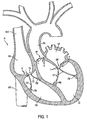
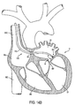
FIG. 1 is a side-sectional view of a human heart showing major structures of the heart, including those pertaining to valvular degeneration; -
FIG. 2 is a side view of apparatus of a first embodiments constructed in accordance with the present invention; -
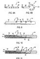
FIGS. 3A-3C are, respectively, a side view of an end effector for use with the apparatus ofFIG. 2 and a sectional view through its catheter along sectional view line A--A, a side view of an alternative end effector and a sectional view of its catheter along view line B--B, and a side view of a still further alternative end effector; -
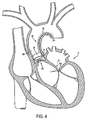
FIG. 4 is a sectional view through the human heart, depicting a method of using the apparatus ofFIG. 2 to shrink tissue in an annulus surrounding the leaflets of a regurgitating valve; -
FIGS. 5A and 5B are schematic views of alternative apparatus -
FIGS. 6A-6D are views of a still further alternative, apparatus having barbs, and illustrating a method of use; -
FIGS. 7A-7C are schematic views showing, respectively, an alternative end effector ofFIGS. 6 having electrically insulated barbs, a method of using the end effector to thermally treat tissue, and a temperature profile within the tissue during treatment; -
FIGS. 8A and 8B are side views of another alternative apparatus having multipolar, individual electrodes; -
FIG. 9 is a side view of an alternative example of the apparatus ofFIG. 8 having individual ultrasonic transducers; -
FIG. 10 is a side-sectional view of another alternative, example of the apparatus ofFIG. 8 having individual laser fibers; -
FIG. 11 is a side-sectional view of an alternative example of the apparatus ofFIGS. 8-10 having individual barb members that may comprise multipolar electrodes, ultrasonic transducers, or laser fibers; -
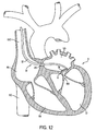
FIG. 12 is a sectional view through the human heart, illustrating an alternative method of introducing apparatus of the first family of embodiments to a treatment site; -
FIGS. 13A and 13B are views of an alternative apparatus shown, respectively, in schematic side view and in use shrinking an annulus of tissue; -
FIGS. 14A and14B are, respectively, a side view of an alternative, example of the apparatus ofFIG. 2 , and a method of using the embodiment via the introduction technique ofFIG. 12 ; -
FIGS. 15A and 15B are isometric views of an alternative end effector for use with the apparatus ofFIGS. 14 ; -
FIG. 16 is a top view of an example apparatus; -
FIG. 17A-17C are views of end effectors for use with the apparatus ofFIG. 16 ; -
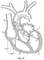
FIG. 18 is a sectional view of the human heart, illustrating a method of using the apparatus ofFIG. 16 to selectively induce a temperature rise in the chordae tendineae sufficient to cause a controlled degree of shortening of the tendineae; -
FIGS. 19A-19C show a section of chordae tendineae and illustrate a method of shrinking the tendineae in a zig-zag fashion using the end effector ofFIG. 17C with the apparatus ofFIG. 16 ; -
FIGS. 20A-20C show, respectively, a side view of an intact tendineae, a side view of the tendineae after treatment by a shrinkage technique, and a cross section through the tendineae along sectional view line C--C ofFIG. 20A after treatment by an alternative shrinkage technique; -
FIGS. 21A and 21B are side views of an example apparatus shown in a collapsed delivery configuration and in an expanded deployed configuration; -
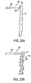
FIGS. 22A and 22B are schematic views depicting a method of using the apparatus ofFIGS. 21 to mechanically shorten an effective length of chordae tendineae; and -
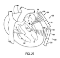
FIG. 23 is a side view, partially in section, illustrating a method and apparatus for non-invasive coagulation and shrinkage of scar tissue in the heart, or shrinkage of the valve structures of the heart. - With reference to
FIG. 1 , a sectional view through human heart H is presented. Major structures labeled include the right atrium RA, left atrium LA, right ventricle RV, left ventricle LV, superior vena cava SVC, inferior vena cava IVC, and ascending aorta AA. Structures that may be involved in valvular degeneration and regurgitation are also labeled, including the papillary muscles PM, chordae tendineae CT, valve leaflets L, and annuluses of tissue surrounding the leaflets A, as well as the tricuspid valve TV, the bicuspid or mitral valve MV, and the aortic valve AV. The pulmonary valve PV is not seen in the cross section ofFIG. 1 , but may also experience valvular degeneration. As discussed previously, degenerative valvular disease often leads to valvular regurgitation, which is typically characterized by an expanded valve annulus A or by lengthened chordae tendineae CT. Loose chordae tendineae may result from ischemic heart disease affecting the papillary muscles PM, which attach to the chordae tendineae and act to regulate flow through leaflets L. - The present invention therefore provides an apparatus for shrinking or reconfiguring tissue, such as annulus A or chordae tendineae CT. Embodiments of the present invention advantageously may be employed to modify flow regulation characteristics of a cardiac valve or its component parts, as well as to modify flow regulation in other lumens of the body, including, for example, the urinary sphincter, digestive system valves, leg vein valves, etc., where thermal shrinkage or mechanical reconfiguration of tissue may provide therapeutic benefit.
-
Figures 2, 3A, 3B , and4 illustrate apparatus of a first embodiment of the present invention. The embodiment has an end effector that induces a temperature rise in an annulus of tissue surrounding the leaflets of a valve sufficient to cause shrinkage of the tissue, thereby reducing a diameter of the annulus and causing the valve to close more tightly. - Referring to
FIG. 2 ,apparatus 30 comprisescatheter 32 havingend effector 34 in a distal region of the catheter.End effector 34 may be collapsible within and extendable beyond the distal end ofcatheter 30 to permit percutaneous delivery to a treatment site.End effector 34 has an annular shape to facilitate treatment of an annulus of tissue, as well as stabilization against the walls of a treatment site. - With reference to
FIGS. 3A-3B , alternative embodiments ofend effector 34 andcatheter 32 are described. InFIG. 3A ,end effector 34 comprisesexpandable balloon 40.Balloon 40 comprisebipolar electrodes Balloon 40 further compriseslumen 44 to facilitate unimpeded blood flow or fluid transport therethrough, andtemperature sensors 46 to monitor shrinkage of tissue caused by current flow betweenbipolar electrodes Sensors 46 may comprise, for example, standard thermocouples, or any other temperature sensor known in the art. - The end effector of
FIG. 3A is thus capable of achieving controlled luminal shrinkage while allowing blood to pass through the center ofballoon 40.Electrodes balloon 40 and may inject an RF electrical current into the wall of a treatment site, such as an annulus or lumen, to shrink collagen contained therein. Furthermore,balloon 40 may be inflated with a circulating coolant C, such as water, to cool the surface ofballoon 40 and thereby minimize thermal damage at the surface of the treatment site. Thermally damaged tissue may be thrombogenic and may form thrombus on its surface, leading to potentially lethal complications. -
FIG. 3A also provides a cross section through an embodiment ofcatheter 32, along sectional view line A--A, for use in conjunction with the balloon embodiment ofend effector 34.Catheter 32 comprisescoolant lumens balloon 40, respectively. It further compriseswires 49a-49c, electrically coupled toelectrode 42a,electrode 42b, andtemperature sensors 46, respectively. - In
FIG. 3B , an alternative embodiment ofend effector 34 andcatheter 32 is presented. Instead of RF energy, the heating element in this embodiment is a laser source (not shown) coupled tofiber optic cable 50 havingside firing tip 51. The laser source injects light energy into the wall of a treatment site viafiber optic cable 50, thereby thermally shrinking the tissue. The wavelength of the laser may be selected to penetrate tissue to a desired depth. Furthermore, a plurality offiber optic cables 50, coupled to the laser source and disposed about the circumference ofballoon 40, may be provided. -
Balloon 40 is substantially transparent to the laser energy, and coolant C may again serve to cool the surface ofballoon 40, thereby minimizing damage at the surface of the treatment site. The circulating stream of coolant C maintains the temperature of surface tissue layers at a sufficiently low level to prevent thermal damage, and thus, to prevent formation of thrombus.Temperature sensor 46 optionally may also be provided. -
FIG. 3C describes an example alternative end effector which comprises wrappedsheet 52 incorporating one or more electrodes on its surface.Sheet 52 may be advanced to a treatment site in a collapsed delivery configuration within a lumen ofcatheter 32, and may then be unfurled to an expanded deployed configuration wherein it contacts the interior wall of the treatment site and may be energized to shrink tissue. - Referring now to
FIG. 4 , a method of usingapparatus 30 to thermally shrink an annulus of tissue is described.End effector 34 is placed in intimate contact with the inner wall of a blood vessel or other body lumen. In the valvular regurgitation treatment technique ofFIG. 4 ,end effector 34 is percutaneously delivered just proximal of aortic valve AV within ascending aorta AA at annulus of tissue A supporting leaflets L, using well-known techniques. Aortic valve AV suffers from valvular degeneration, leading to regurgitation.End effector 34 delivers energy to annulus A sufficient to heat and shrink the annulus, thus enhancing function of the degenerative valve. Collagen within annulus A shrinks and reduces a diameter of the annulus. Leaflets L are approximated towards one another, as seen in dashed profile inFIG. 4 , and valvular regurgitation is reduced or eliminated. In addition to valvular regurgitation, the technique is expected to effectively treat aortic insufficiency. -
End effector 34 stabilizesapparatus 30 against the wall of a body passageway. Once stabilized, a source of energy may be applied to the wall to thermally shrink the tissue contained in the wall. In addition to the application ofFIG. 4 , treatment may be provided, for example, to the annulus of mitral valve MV, to the urinary sphincter for treatment of incontinence, to digestive system valves for treatment of acid reflux, to leg vein valves, and to any other annulus of tissue where treatment is deemed beneficial. - With reference to
FIGS. 5A and 5B , alternative examples of the apparatus ofFIG. 2 are described. InFIG. 5A ,apparatus 60 comprisescatheter 62 having a lumen, in whichend effector 64 is advanceably disposed.End effector 64 comprisesmonopolar electrode 66, which is fabricated in an arc from a shape memory alloy, such as spring steel or nitinol, to approximate the shape of an annulus of tissue at a treatment site within a patient.Electrode 66 may be retracted within the lumen ofcatheter 62 to facilitate transluminal, percutaneous delivery to the treatment site. Once in position,electrode 66 may be advanced out of a distal region ofcatheter 62. The electrode resumes its arc shape and approximates the wall of the treatment site. -
Monopolar electrode 66 is electrically coupled toRF source 68, which is positioned outside of the patient.RF source 68 is, in turn, coupled toreference electrode 69. WhenRF source 68 is activated, current flows betweenmonopolar electrode 66 andreference electrode 69, which may, for example, be attached to the exterior of the patient in the region of the treatment site. RF current flows into the wall of the treatment site, thereby effecting annular tissue shrinkage, as described previously. - In
FIG. 5B , a bipolar embodiment is provided.Apparatus 70 comprisescatheter 72 andend effector 74.End effector 74 comprises a plurality of atraumatic tippedlegs 76 that are electrically coupled by a plurality of current carryingwires 78 to an RF source (not shown). The plurality of legs contact the wall of a treatment site and inject current into the wall. The current flows between the tips of the legs. Alternatively, the plurality of legs may comprise a monopolar electrode coupled by a single wire to the RF source, and current may flow between the plurality of legs and a reference electrode, as inFIG. 5A . - Referring to
FIGS. 6A-6D , another alternative example of the apparatus ofFIG. 2 is described.FIG. 6A showsapparatus 80 in side-sectional view in a retracted delivery configuration.Apparatus 80 comprisescatheter 82 andend effector 84.Catheter 82 further comprisescentral bore 86, a plurality of side bores 88, andoptional temperature sensors 90.End effector 84 may, for example, be fabricated from nitinol or spring steel, and comprisesconductive shaft 92 having a plurality of radially extendingelectrodes 94 withoptional barbs 96.Conductive shaft 92 is electrically coupled toRF source 98, which is electrically coupled toreference electrode 99.Conductive shaft 92 is disposed withincentral bore 86, whileelectrodes 94 are disposed within side bores 88. -
End effector 84 is advanceable with respect tocatheter 82. When advanced distally,apparatus 80 assumes the expanded deployed configuration ofFIG. 6B , whereinelectrodes 94 extend through side bores 88 beyond the surface ofcatheter 82.Apparatus 80 is also configured such that its distal region may approximate the shape of an annulus of tissue, as described hereinbelow with respect toFIG. 6D , and is thus suited for both linear and circular subsurface tissue coagulation and shrinkage. -
FIGS. 6C and 6D provide a method of usingapparatus 80 to treat annulus of tissue A surrounding a heart valve.Apparatus 80 is percutaneously advanced to the surface of a heart valve in the delivery configuration ofFIG. 6C . Once positioned at annulus A, the distal region ofapparatus 80 approximates the shape of the annulus, as seen inFIG. 6D . This may be accomplished, for example, with a steering mechanism comprising two purchase points or a pre-shaped tip that is retracted within a straight guiding catheter to allow insertion into the vascular system, as described inU.S. Patent No. 5, 275, 162 . - Once inserted, the pre-shaped tip is advanced out of the guide catheter and recovers its preformed shape.
- With
apparatus 80 approximating annulus A,end effector 84 is distally advanced with respect tocatheter 82, thereby selectively advancingelectrodes 94 into the annulus.RF source 98 then provides RF current, which flows betweenelectrodes 94 andreference electrode 99. The annulus of tissue shrinks, bringing valve leaflets into proper position and minimizing or eliminating regurgitation through the valve. -
Catheter 82 insulatesconductive shaft 92 from annulus A, thereby protecting surface tissue and only allowing coagulation at depth in treatmentzones surrounding electrodes 94. To further ensure that coagulation only occurs at depth, a coolant, such as saline, may be introduced throughcentral bore 86 and side bores 88 ofcatheter 82 to the surface of annulus A, thereby cooling and flushing the area whereelectrodes 94 penetrate the tissue. It is expected that such liquid infusion will keep the surface of the annulus clean and will prevent thrombus formation in response to thermal damage. - Referring now to
FIG. 7A-7C , analternative end effector 84 ofFIGS. 6 is described. The end effector ofFIGS. 7 is equivalent to the end effector ofFIGS. 6 except that it is coated with electrically insulating layer I. Insulation layer I covers the entire exterior ofend effector 84, except at the distal ends of the plurality ofelectrodes 94. The layer is preferably sufficiently thin to allow insertion ofelectrodes 94 into tissue T without impediment. The exposed distal ends of the electrodes are configured to deliver energy into subsurface tissue at treatment zones Z. The zones may be ideally modeled as spheres of subsurface tissue. Tissue shrinks within treatment zones Z without damaging surface tissue, as seen inFIG. 7B . - The size of treatment zones Z may be controlled to ensure that tissue remodeling only occurs at depth. Assuming a temperature T1, at which tissue damage is negligible, the magnitude of current passed through tissue T may be selected (based on the material properties of the tissue and the depth of insertion of
electrodes 94 within the tissue) such that the temperature decays from a temperature To at a position Do at the surface of anelectrode 94 to the benign temperature T1 at a distance D1 from the surface of the electrode. The distance D1 may be optimized such that it is below the surface of tissue T. An illustrative temperature profile across a treatment zone Z is provided inFIG. 7C . - With reference to
FIGS. 8A and 8B , another alternative apparatus ofFIG. 6 is described.Apparatus 100 comprisescatheter 102 andend effector 104.End effector 104 further comprises a plurality of individual,multipolar electrodes 106, which are electrically coupled to an RF or other current source (not shown) by a plurality of current carryingwires 108. As with the embodiments ofFIGS. 6 and7 ,apparatus 100 is configured such thatend effector 104 may approximate an annulus, as seen inFIG. 8B . - Referring to
FIGS. 9-11 , alternative example of the apparatus ofFIGS. 8 are described. InFIG. 9 ,apparatus 110 comprisescatheter 112 andend effector 114.End effector 114 comprises a plurality ofacoustic heating elements 116.Acoustic elements 116 may, for example, comprise ultrasonic transducers. The acoustic energy may further be focused by appropriate means, for example, by lenses, such that a tissue damage threshold sufficient to cause shrinkage is only attained at a specified depth within treatment site tissue, thereby mitigating surface tissue damage and thrombus formation.Acoustic elements 116 are connected to appropriate controls (not shown).Apparatus 110, and any other apparatus described herein, may optionally comprisetemperature sensors 118. - In
FIG. 10 ,apparatus 120 comprisescatheter 122 andend effector 124.Catheter 122 comprises a plurality ofcentral bores 126 and a plurality of side bores 128, as well as a plurality ofoptional temperature sensors 130.End effector 124 comprises a plurality of side-firing fiberoptic laser fibers 132 disposed withincentral bores 126 ofcatheter 122. The fibers are aligned such that they may deliver energy through side bores 128 to heat and induce shrinkage in target tissue.Fibers 132 are coupled to a laser source (not shown), as discussed with respect toFIG. 3B . Suitable wavelengths for the laser source preferably range from visible (488-514 nm) to infrared (.9-10.6 microns), wherein each wavelength has an ability to heat tissue to a predetermined depth. As an example, a preferred laser source comprises a continuous wave laser having a 2.1 micron wavelength, which will shrink and heat tissue to a depth of 1-2 mm. - In
FIG. 11 ,apparatus 140 comprisescatheter 142 andend effector 144.Catheter 132 comprisescentral bores 146 and side bores 148.Catheter 132 further comprisestemperature sensors 150 that are configured to penetrate superficial tissue layers to measure temperature at depth.Temperature sensors 150 may be retractable and extendable to facilitate percutaneous delivery ofapparatus 140.End effector 144 comprisesfibers 152 disposed withincentral bores 146.Fibers 152 are retractable within and extendable beyond side bores 148.Fibers 152 are preferably sharpened to facilitate tissue penetration and energy delivery to subsurface tissue, thereby inducing shrinkage of the tissue. -
Fibers 152 may comprise any of a number of energy delivery elements. For example,fibers 152 may comprise a plurality of optical fibers coupled to a laser (not shown). The wavelength of the laser may be selected as described hereinabove, while the energy deposited by the fibers may be controlled responsive to the temperature recorded bysensors 150. Thus, for example, a controller (not shown) may be provided to switch off the laser once a preset temperature, for example, 45°C-75°C, is attained, thereby ensuring that a sufficiently high temperature is achieved to cause tissue shrinkage without inadvertently damaging surrounding tissues. -
Fibers 152 may alternatively comprise a plurality of multipolar electrodes. Each electrode may be capable of injecting RF energy into tissue independently. Alternatively, current may be passed between a pair of adjacent or non-adjacent electrodes to heat intervening tissue. - Referring now to
FIG. 12 , an alternative method of introducing apparatus, to a treatment site is described.Apparatus 30 ofFIG. 2 is been introduced to the annulus of tissue A surrounding mitral valve MV via the venous circulatory system.Catheter 32 is transluminally inserted via the jugular vein and superior vena cava SVC. The distal end of the catheter or a separate instrument then penetrates atrial septum As using a procedure known as septostomy. Once the septum is perforated,end effector 34 may be inserted into left atrium LA and positioned over mitral valve annulus A to effect the thermal treatment described hereinabove. The tricuspid valve in the right ventricle, and the pulmonic valve, may also be treated in the same manner using a venous approach. - Referring to
FIGS. 13A and 13B , an alternative example, of the apparatus ofFIG. 2 is described that may be introduced using the technique ofFIG. 4 , the technique ofFIG. 12 , or by another suitable technique.Apparatus 160 comprisescatheter 162 andend effector 164.End effector 164 comprises adjustable,heatable loop 166, which is configured for dynamic sizing to facilitate positioning next to tissue at a treatment site. The size ofloop 166 is adjusted so as to lie contiguous with annulus of tissue A at a treatment site, as seen inFIG. 13B . The loop may be collapsible withincatheter 162 to facilitate percutaneous delivery and is electrically coupled toRF source 168, which is electrically coupled toreference electrode 170.Loop 166 may be fabricated from nitinol, copper, or any other suitably conductive and ductile material. - Referring to
FIGS. 14A and14B , a still further alternative example of the apparatus ofFIG. 2 , and a method of using the embodiment with the introduction technique ofFIG. 12 , is described.Apparatus 170 comprisescatheter 172 andend effector 174.End effector 174 is capable of grabbing and penetrating tissue, as well as delivering RF energy into tissue.End effector 174 comprisesjaws End effector 174 hastemperature sensor 178 to control power delivered to the tissue, again as described hereinabove. - With reference to
FIG. 14B , a method of usingapparatus 170 via a septostomy introduction technique to treat mitral valve regurgitation is described. In particular, jaws 176 ofend effector 174 are actuated to engage individual sections of valve annulus A so as to penetrate into the collagenous sublayers and to thermally shrink those sublayers. The procedure may be repeated at multiple locations around the perimeter of annulus A until regurgitation is minimized or eliminated. -
FIGS. 15A and 15B show an alternative end effector for use withapparatus 170 ofFIGS. 14 .End effector 180 is shown in an open position and in a closed position, respectively, and comprisesjaws End effector 180 is similar to endeffector 174, except that jaws 182 are configured to engage tissue with a forceps grasping motion whereinbent tips - With reference now to
FIGS. 16-20 , alternative apparatus are described. These examples are provided with an end effector that selectively induces a temperature rise in the chordae tendineae sufficient to cause a controlled degree of shortening of the chordae tendineae, thereby enabling valve leaflets to be properly aligned. - A preferred use for these example apparatus is in treatment of mitral valve regurgitation. Mitral valve regurgitation has many causes, ranging from inherited disorders, such as Marphan"s syndrome, to infections and ischemic disease. These conditions affect the macromechanical condition of the mitral valve and prevent the valve from closing completely. The resulting gap in the leaflets of the valve permit blood to regurgitate from the left ventricular chamber into the left atrium.
- Mechanically, the structural defects characterizing mitral valve regurgitation include: (1) the chordae tendineae are too long due to a given disease state; (2) papillary muscle ischemia changes the shape of the papillary muscle, so that attached chordae tendineae no longer pull the leaflets of the mitral valve completely shut; (3) the annulus of the mitral valve becomes enlarged, resulting in the formation of a gap between the leaflets when closed; and (4) there is an inherent weakness in the leaflets, leaving the leaflets floppy and dysfunctional.
- A temperature rise is induced in the support structure of the mitral valve to cause shrinkage that modifies the geometry of the valve to restore proper stopping of blood backflow and thereby regurgitation. This process is depicted in
FIGS. 18-20 using the apparatus ofFIGS. 16 and 17 to selectively shrink portions of the chordae tendineae, thereby bringing leaflets of the mitral valve leaflets into alignment. Apparatus of the second family may also be used in treatment of aortic valve regurgitation, and in treatment of a variety of other ailments that will be apparent to those of skill in the art. - Referring to
FIG. 16 ,apparatus 200 comprisescatheter 202 andend effector 204.Catheter 204 optionally comprises collapsible andexpandable stabilizer 206, configured to stabilizeapparatus 200 in a body lumen.Stabilizer 206 may comprise, for example, struts or an inflatable balloon. -
End effector 204 may be collapsible to a delivery configuration withincatheter 202, and may expand to a delivery configuration beyond a distal end of the catheter.End effector 204 is configured to engage, heat, and shrink chordae tendineae. Various sources of energy may be used to impart heat to the collagenous tissue and thereby shrink it, including RF energy, focused ultrasound, laser energy, and microwave energy. In addition, chemical modifiers, such as aldehydes, may be used. For laser embodiments, a preferred laser is a continuous wave Holmium:Yag laser, with application of visible or infrared laser energy in the wavelength range of 400 nanometers to 10.6 micrometers. - With reference to
FIGS. 17A-17c , examples ofend effector 204 are described. InFIG 17A , the end effector comprises a gripping mechanism that carries the heating element.Arms Arms Heating elements 212 andtemperature sensors 214 are attached to the arms.Heating elements 212 may comprise electrodes, acoustic transducers, side-firing laser fibers, radioactive elements, etc. It may be desirable to employ a saline flush withheating elements 212 to prevent coagulation of blood caught between arms 210. -
FIG. 17B shows an example ofend effector 204 with fixed,straight arms FIG. 17C shows an embodiment of the endeffector having arms Multiple heating elements 212 are disposed onarm 230a. When heatingelements 212 comprise bipolar electrodes, current flow through the tendineae using the embodiment ofFIG. 17C may be achieved primarily along a longitudinal axis of the tendineae, as opposed to along a radial axis of the tendineae, as will be achieved with the embodiment ofFIG. 17A . These alternative heating techniques are described in greater detail hereinbelow with respect toFIGS. 19 and 20 . - Referring to
FIG. 18 , a method of using the apparatus to induce shrinkage of chordae tendineae CT is described.Catheter 202 ofapparatus 200 is advanced percutaneously, using well-known techniques, through the ascending aorta AA and aortic valve AV into the left ventricle LV, withend effector 204 positioned within the catheter in the collapsed delivery configuration.Stabilizer 206 is then deployed to fixcatheter 202 in ascending aorta AA, thereby providing a stationary leverage point. -
End effector 204 is expanded to the deployed configuration distal ofcatheter 202. The end effector is steerable within left ventricle LV to facilitate engagement of chordae tendineae CT.End effector 204, as well as any of the other end effectors or catheters described herein, may optionally comprise one or more radiopaque features to ensure proper positioning at a treatment site.End effector 204 is capable of moving up and down the chordae tendineae to grab and selectively singe certain sections thereof, as illustrated in dotted profile inFIG. 18 , to selectively shorten chordae tendineae CT, thereby treating valvular regurgitation. - When energy is transmitted through tissue utilizing one of the embodiments of this invention, the tissue absorbs the energy and heats up. It may therefore be advantageous to equip the end effector with temperature or impedance sensors, as seen in the embodiments of
FIGS. 17 , to output a signal that is used to control the maximum temperature attained by the tissue and ensure that the collagen or other tissues intended to be shrunk are heated only to a temperature sufficient for shrinkage, for example, a temperature in the range of 45°C-75°C, and even more preferably in the range of 55°C-65°C. Temperatures outside this range may be so hot as to turn the tissue into a gelatinous mass and weaken it to the point that it loses structural integrity. A closed loop feedback system advantageously may be employed to control the quantity of energy deposited into the tissue responsive to the output of the one or more sensors. In addition, the sensors may permit the clinician to determine the extent to which the cross-section of a chordae has been treated, thereby enabling the clinician to heat treat only a portion of the cross-section. - This technique is illustrated in
FIGS. 19 and 20 , in which alternating bands, only a single side, or only a single depth of the chordae is shrunk to leave a "longitudinal intact fiber bundle." This method may be advantageous in that, by avoiding heat treatment of the entire cross section of the chordae, there is less risk of creating mechanical weakness. -
FIGS. 19A-19C depict a method of shrinking a section of chordae tendineae CT in a zig-zag fashion using the embodiment ofend effector 204 seen inFIG. 17C . InFIG. 19A , the tendineae has an initial effective or straight length L1 . Arms 230 engage chordae tendineae CT, andheating elements 212 are both disposed on the same side of the tendineae onarm 230a. The heating elements may comprise bipolar electrodes, in which case the path of current flow through tendineae CT is illustrated by arrows inFIG. 19A . - Collagen within the tendineae shrinks, and chordae tendineae CT assumes the configuration seen in
FIG. 19B . Treatment zone Z shrinks, and the tendineae assumes a shorter effective length L2 . Treatment may be repeated on the opposite side of the tendineae, as seen inFIG. 19C , so that the tendineae assumes a zig-zag configuration of still shorter effective length L3 . In this manner, successive bands of treatment zones Z and intact longitudinal fiber bundles may be established. - An additional pair of bipolar electrodes optionally may be disposed on
arm 230b of the end effector to facilitate treatment in bands on opposite sides of chordae tendineae CT. The depth of shrinkage attained withapparatus 200 is a function of the distance between the electrodes, the power, and the duration of RF energy application. If, laser energy is applied, the wavelengths of energy application may be selected to provide only partial penetration of the thickness of the tissue. For example, continuous wave Holmium:YAG laser energy having a wavelength of 2.1 microns penetrates a mere fraction of a millimeter and may be a suitable energy source. -
FIGS. 20A-20C illustrate additional shrinkage techniques. Intact chordae tendineae CT is seen inFIG. 20A. FIG. 20B demonstrates shrinkage withapparatus 200 only on one side of the chordae, using the technique described with respect toFIGS. 19. FIG. 20C demonstrates shrinkage with, for example the end effector ofFIGS. 17A or 17B , wherein, for example, bipolar current flows across the tendineae and treats the tendineae radially to a certain preselected depth. When viewed in cross-section along sectional view line C--C ofFIG. 20A , chordae tendineae CT has an intact longitudinal fiber bundle core C surrounded by treatment zone Z. - With reference to
FIGS. 21-22 , alternative apparatus are described. These embodiments are provided with an end effector comprising a mechanical reconfigurer configured to engage a longitudinal member, such as the chordae tendineae. The reconfigurer forces the longitudinal member into a tortuous path and, as a result, reduces the member's effective overall or straight length. - Referring to
FIGS. 21A and 21B ,apparatus 300 comprisescatheter 302 andend effector 304.End effector 304 comprisesmechanical reconfigurer 306, adapted to mechanically alter the length of a longitudinal member, for example, chordae tendineae.Reconfigurer 306 comprises a preshaped spring fabricated from a shape memory alloy, for example, nitinol, spring steel, or any other suitably elastic and strong material.Reconfigurer 306 is preshaped such that there is no straight path through its loops. Overlap between adjacent loops is preferably minimized. The shape ofreconfigurer 306 causes longitudinal members , such as chordae tendineae, passed therethrough to assume a zig-zag configuration and thereby be reduced in effective length.Reconfigurer 306 is collapsible to a delivery configuration withincatheter 302, as seen inFIG. 21A , and is expandable to a deployed configuration, as seen inFIG. 21B . The reconfigurer optionally may be selectively detachable fromcatheter 302. - With reference to
FIGS. 22A and 22B , a method of usingapparatus 300 to mechanically shorten chordae tendineae CT is described.Apparatus 300 is advanced to the chordae tendineae, for example, using the technique described hereinabove with respect toFIG. 18 .End effector 304 is then expanded from the delivery configuration seen inFIG. 22A to the deployed configuration ofFIG. 22B .Mechanical reconfigurer 306 regains its preformed shape, and chordae tendineae CT is passed through a tortuous path that reduces its effective length, thereby treating valvular regurgitation.Reconfigurer 306 may then be detached fromapparatus 300 and permanently implanted in the patient, or the reconfigurer may be left in place for a limited period of time to facilitate complementary regurgitation treatment techniques. - Other embodiments of the third family in accordance with the present invention will be apparent to those of skill in the art in light of this disclosure.
- Referring now to
FIG. 23 , apparatus alternative apparatus is described, - Apparatus and methods are provided for noninvasively coagulating and shrinking scar tissue around the heart, or valve structures inside the heart, using energy delivered via high intensity, focused
ultrasound Apparatus 350 comprisescatheter 352 andend effector 354.End effector 354 comprisesultrasonic transducer 356 and focusingmeans 358, for example, a lens. Focused ultrasound is propagated and directed with a high level of accuracy at the chordae CT, the annuluses A of the valves or at a section of bulging wall of the heart, using , for example, echocardiography or MRI for guidance. As with the previous embodiments, the shrinkage induced by energy deposition is expected to reduce valvular regurgitation.Apparatus 350 may also be used to reduce ventricular volume and shape, in cases where there is bulging scar tissue on the wall of the left ventricle LV secondary to acute myocardial infarction. - All of the above mentioned methods and apparatus may be used in conjunction with flow-indicating systems, including, for example, color Doppler flow echocardiography, MRI flow imaging systems, or laser Doppler flow meters. Application of energy from the end effector may be selected such that regurgitation stops before the procedure is completed, as verified by the flow-indicating system. Alternatively, the procedure may be "overdone" to compensate for expected tissue relapse, without compromising the ultimate outcome of the procedure.
- Additionally, all of the foregoing apparatus and methods optionally may be used in conjunction with ECG gating, thereby ensuring that tissue is at a specified point in the cardiac cycle before energy is deposited into the tissue. ECG gating is expected to make treatment more reproducible and safer for the patient.
- Although preferred illustrative embodiments of the present invention are described above, it will be evident to one skilled in the art that various changes and modifications may be made without departing from the invention. It is intended in the appended claims to cover all such changes and modifications that fall within the true scope of the invention.
Claims (15)
- Apparatus (30) for treating tissue (T) at a target site to modify flow through a valve (AV,TV,MV), the apparatus (30) comprising:a catheter (32) having a distal end region, the catheter configured for transluminal delivery of the end region to the target site; andan end effector (34) in communication with the distal end region, the end effector configured to transfer energy to the tissue at the target site to induce thermal shrinkage of collagen in the tissue, thereby modifying flow through the valve,the end effector (34) comprising an expandable balloon configured to approximate the shape of the tissue while transferring energy to the tissue;the apparatus (30) being arranged to modify flow through the valve (AV,TV,MV) by reducing a circumference of the valve,the apparatus being characterized in that the expandable balloon has an annular shape.
- The apparatus of claim 1, wherein the balloon comprises a lumen configured to allow fluid to pass through the centre of the balloon and the tissue at the target site comprises an annulus of tissue surrounding a valve.
- The apparatus (30) of claim 1, wherein the tissue at the target site comprises an annulus (A) of tissue surrounding a valve (AV,TV,MV).
- The apparatus (30) of claim 1, wherein the tissue at the target site comprises a support structure (PM,CT) of a cardiac valve (AV,TV.MV).
- The apparatus (30) of claim 4, wherein the support structure is chosen from the group consisting of a chordae tendineae (CT) and a papillary muscle (PM).
- The apparatus (30) of claim 5, wherein modifying flow through the valve (TV,MV) comprises shortening the chordae tendineae (CT) to properly align leaflets (L) of the valve (TV,MV).
- The apparatus (30) of claim 1, wherein the tissue at the target site comprises a leaflet (L) of a cardiac valve (MV,TV,AV).
- The apparatus (30) of claim 1 wherein the end effector (34) comprises a temperature sensor (46).
- The apparatus (30) of claim 1, wherein the end effector (34) comprises a tissue heating element.
- The apparatus (30) of claim 1, wherein the end effector (34) comprises coolant to minimize surface tissue damage at the target site.
- The apparatus (30) of claim 1, wherein the end effector (34) is configured to engage tissue.
- The apparatus (30) of claim 1, wherein the catheter has a coolant lumen for circulating coolant into and out of the expandable balloon.
- The apparatus (30) of claim 1, further comprising a flow-indicating system (350) in communication with the end effector (34).
- The apparatus (30) of claim 13, wherein the flow-indicating system (350) is chosen from the group consisting of a color Doppler flow echocardiography system, an MRI flow imaging system, and a laser Doppler flow meter.
- The apparatus (30) of claim 1, further comprising an ECG gating system in communication with the end effector (34).
Applications Claiming Priority (3)
| Application Number | Priority Date | Filing Date | Title |
|---|---|---|---|
| US14107799P | 1999-06-25 | 1999-06-25 | |
| US141077P | 1999-06-25 | ||
| PCT/US2000/017270 WO2001000114A1 (en) | 1999-06-25 | 2000-06-23 | Apparatus and methods for treating tissue |
Publications (3)
| Publication Number | Publication Date |
|---|---|
| EP1198213A1 EP1198213A1 (en) | 2002-04-24 |
| EP1198213A4 EP1198213A4 (en) | 2005-07-20 |
| EP1198213B1 true EP1198213B1 (en) | 2010-06-09 |
Family
ID=22494067
Family Applications (1)
| Application Number | Title | Priority Date | Filing Date |
|---|---|---|---|
| EP00944803A Expired - Lifetime EP1198213B1 (en) | 1999-06-25 | 2000-06-23 | Apparatus for treating tissue |
Country Status (7)
| Country | Link |
|---|---|
| US (1) | US6669687B1 (en) |
| EP (1) | EP1198213B1 (en) |
| JP (1) | JP4576521B2 (en) |
| AT (1) | ATE470414T1 (en) |
| AU (1) | AU5884400A (en) |
| DE (1) | DE60044531D1 (en) |
| WO (1) | WO2001000114A1 (en) |
Cited By (12)
| Publication number | Priority date | Publication date | Assignee | Title |
|---|---|---|---|---|
| US10856984B2 (en) | 2017-08-25 | 2020-12-08 | Neovasc Tiara Inc. | Sequentially deployed transcatheter mitral valve prosthesis |
| US10940001B2 (en) | 2012-05-30 | 2021-03-09 | Neovasc Tiara Inc. | Methods and apparatus for loading a prosthesis onto a delivery system |
| US11311376B2 (en) | 2019-06-20 | 2022-04-26 | Neovase Tiara Inc. | Low profile prosthetic mitral valve |
| US11357622B2 (en) | 2016-01-29 | 2022-06-14 | Neovase Tiara Inc. | Prosthetic valve for avoiding obstruction of outflow |
| US11389291B2 (en) | 2013-04-04 | 2022-07-19 | Neovase Tiara Inc. | Methods and apparatus for delivering a prosthetic valve to a beating heart |
| US11413139B2 (en) | 2011-11-23 | 2022-08-16 | Neovasc Tiara Inc. | Sequentially deployed transcatheter mitral valve prosthesis |
| US11419720B2 (en) | 2010-05-05 | 2022-08-23 | Neovasc Tiara Inc. | Transcatheter mitral valve prosthesis |
| US11464631B2 (en) | 2016-11-21 | 2022-10-11 | Neovasc Tiara Inc. | Methods and systems for rapid retraction of a transcatheter heart valve delivery system |
| US11491006B2 (en) | 2019-04-10 | 2022-11-08 | Neovasc Tiara Inc. | Prosthetic valve with natural blood flow |
| US11497602B2 (en) | 2012-02-14 | 2022-11-15 | Neovasc Tiara Inc. | Methods and apparatus for engaging a valve prosthesis with tissue |
| US11602429B2 (en) | 2019-04-01 | 2023-03-14 | Neovasc Tiara Inc. | Controllably deployable prosthetic valve |
| US11779742B2 (en) | 2019-05-20 | 2023-10-10 | Neovasc Tiara Inc. | Introducer with hemostasis mechanism |
Families Citing this family (262)
| Publication number | Priority date | Publication date | Assignee | Title |
|---|---|---|---|---|
| US7620290B2 (en) * | 1995-08-31 | 2009-11-17 | Biolase Technology, Inc. | Modified-output fiber optic tips |
| FR2768324B1 (en) | 1997-09-12 | 1999-12-10 | Jacques Seguin | SURGICAL INSTRUMENT FOR PERCUTANEOUSLY FIXING TWO AREAS OF SOFT TISSUE, NORMALLY MUTUALLY REMOTE, TO ONE ANOTHER |
| US7364577B2 (en) | 2002-02-11 | 2008-04-29 | Sherwood Services Ag | Vessel sealing system |
| US6752813B2 (en) | 1999-04-09 | 2004-06-22 | Evalve, Inc. | Methods and devices for capturing and fixing leaflets in valve repair |
| US20040044350A1 (en) | 1999-04-09 | 2004-03-04 | Evalve, Inc. | Steerable access sheath and methods of use |
| US7811296B2 (en) | 1999-04-09 | 2010-10-12 | Evalve, Inc. | Fixation devices for variation in engagement of tissue |
| ATE484241T1 (en) | 1999-04-09 | 2010-10-15 | Evalve Inc | METHOD AND DEVICE FOR HEART VALVE REPAIR |
| US8216256B2 (en) | 1999-04-09 | 2012-07-10 | Evalve, Inc. | Detachment mechanism for implantable fixation devices |
| US7563267B2 (en) | 1999-04-09 | 2009-07-21 | Evalve, Inc. | Fixation device and methods for engaging tissue |
| US8285393B2 (en) | 1999-04-16 | 2012-10-09 | Laufer Michael D | Device for shaping infarcted heart tissue and method of using the device |
| US6306132B1 (en) | 1999-06-17 | 2001-10-23 | Vivant Medical | Modular biopsy and microwave ablation needle delivery apparatus adapted to in situ assembly and method of use |
| US6626899B2 (en) | 1999-06-25 | 2003-09-30 | Nidus Medical, Llc | Apparatus and methods for treating tissue |
| SE514718C2 (en) | 1999-06-29 | 2001-04-09 | Jan Otto Solem | Apparatus for treating defective closure of the mitral valve apparatus |
| US6997951B2 (en) * | 1999-06-30 | 2006-02-14 | Edwards Lifesciences Ag | Method and device for treatment of mitral insufficiency |
| US7192442B2 (en) * | 1999-06-30 | 2007-03-20 | Edwards Lifesciences Ag | Method and device for treatment of mitral insufficiency |
| US7004970B2 (en) | 1999-10-20 | 2006-02-28 | Anulex Technologies, Inc. | Methods and devices for spinal disc annulus reconstruction and repair |
| US7951201B2 (en) | 1999-10-20 | 2011-05-31 | Anulex Technologies, Inc. | Method and apparatus for the treatment of the intervertebral disc annulus |
| US8632590B2 (en) | 1999-10-20 | 2014-01-21 | Anulex Technologies, Inc. | Apparatus and methods for the treatment of the intervertebral disc |
| US8128698B2 (en) | 1999-10-20 | 2012-03-06 | Anulex Technologies, Inc. | Method and apparatus for the treatment of the intervertebral disc annulus |
| US7935147B2 (en) | 1999-10-20 | 2011-05-03 | Anulex Technologies, Inc. | Method and apparatus for enhanced delivery of treatment device to the intervertebral disc annulus |
| US7615076B2 (en) | 1999-10-20 | 2009-11-10 | Anulex Technologies, Inc. | Method and apparatus for the treatment of the intervertebral disc annulus |
| US7052516B2 (en) | 1999-10-20 | 2006-05-30 | Anulex Technologies, Inc. | Spinal disc annulus reconstruction method and deformable spinal disc annulus stent |
| US6592625B2 (en) | 1999-10-20 | 2003-07-15 | Anulex Technologies, Inc. | Spinal disc annulus reconstruction method and spinal disc annulus stent |
| US6402781B1 (en) | 2000-01-31 | 2002-06-11 | Mitralife | Percutaneous mitral annuloplasty and cardiac reinforcement |
| US6989028B2 (en) * | 2000-01-31 | 2006-01-24 | Edwards Lifesciences Ag | Medical system and method for remodeling an extravascular tissue structure |
| US6805695B2 (en) | 2000-04-04 | 2004-10-19 | Spinalabs, Llc | Devices and methods for annular repair of intervertebral discs |
| US6810882B2 (en) | 2001-01-30 | 2004-11-02 | Ev3 Santa Rosa, Inc. | Transluminal mitral annuloplasty |
| US7699835B2 (en) | 2001-02-15 | 2010-04-20 | Hansen Medical, Inc. | Robotically controlled surgical instruments |
| US20030135204A1 (en) * | 2001-02-15 | 2003-07-17 | Endo Via Medical, Inc. | Robotically controlled medical instrument with a flexible section |
| US7766894B2 (en) | 2001-02-15 | 2010-08-03 | Hansen Medical, Inc. | Coaxial catheter system |
| US8414505B1 (en) | 2001-02-15 | 2013-04-09 | Hansen Medical, Inc. | Catheter driver system |
| US20080109030A1 (en) | 2001-04-24 | 2008-05-08 | Houser Russell A | Arteriotomy closure devices and techniques |
| US8202315B2 (en) | 2001-04-24 | 2012-06-19 | Mitralign, Inc. | Catheter-based annuloplasty using ventricularly positioned catheter |
| US8992567B1 (en) | 2001-04-24 | 2015-03-31 | Cardiovascular Technologies Inc. | Compressible, deformable, or deflectable tissue closure devices and method of manufacture |
| US8961541B2 (en) | 2007-12-03 | 2015-02-24 | Cardio Vascular Technologies Inc. | Vascular closure devices, systems, and methods of use |
| US7094234B1 (en) * | 2001-08-27 | 2006-08-22 | Medcool, Inc. | Interstitial brain cooling probe and sheath apparatus |
| SE524709C2 (en) | 2002-01-11 | 2004-09-21 | Edwards Lifesciences Ag | Device for delayed reshaping of a heart vessel and a heart valve |
| WO2003055417A1 (en) | 2001-12-28 | 2003-07-10 | Edwards Lifesciences Ag | Delayed memory device |
| US7048754B2 (en) | 2002-03-01 | 2006-05-23 | Evalve, Inc. | Suture fasteners and methods of use |
| US6752767B2 (en) | 2002-04-16 | 2004-06-22 | Vivant Medical, Inc. | Localization element with energized tip |
| US7197363B2 (en) | 2002-04-16 | 2007-03-27 | Vivant Medical, Inc. | Microwave antenna having a curved configuration |
| US7753924B2 (en) | 2003-09-04 | 2010-07-13 | Guided Delivery Systems, Inc. | Delivery devices and methods for heart valve repair |
| US9949829B2 (en) | 2002-06-13 | 2018-04-24 | Ancora Heart, Inc. | Delivery devices and methods for heart valve repair |
| US7883538B2 (en) | 2002-06-13 | 2011-02-08 | Guided Delivery Systems Inc. | Methods and devices for termination |
| US7666193B2 (en) | 2002-06-13 | 2010-02-23 | Guided Delivery Sytems, Inc. | Delivery devices and methods for heart valve repair |
| US8287555B2 (en) | 2003-02-06 | 2012-10-16 | Guided Delivery Systems, Inc. | Devices and methods for heart valve repair |
| US20060122633A1 (en) | 2002-06-13 | 2006-06-08 | John To | Methods and devices for termination |
| US7753858B2 (en) | 2002-06-13 | 2010-07-13 | Guided Delivery Systems, Inc. | Delivery devices and methods for heart valve repair |
| US7753922B2 (en) | 2003-09-04 | 2010-07-13 | Guided Delivery Systems, Inc. | Devices and methods for cardiac annulus stabilization and treatment |
| US7758637B2 (en) | 2003-02-06 | 2010-07-20 | Guided Delivery Systems, Inc. | Delivery devices and methods for heart valve repair |
| US8641727B2 (en) | 2002-06-13 | 2014-02-04 | Guided Delivery Systems, Inc. | Devices and methods for heart valve repair |
| AU2003245507A1 (en) | 2002-06-13 | 2003-12-31 | Guided Delivery Systems, Inc. | Devices and methods for heart valve repair |
| US20040082859A1 (en) | 2002-07-01 | 2004-04-29 | Alan Schaer | Method and apparatus employing ultrasound energy to treat body sphincters |
| CA2494758C (en) * | 2002-08-01 | 2013-03-19 | The General Hospital Corporation | Cardiac devices and methods for minimally invasive repair of ischemic mitral regurgitation |
| US7087064B1 (en) | 2002-10-15 | 2006-08-08 | Advanced Cardiovascular Systems, Inc. | Apparatuses and methods for heart valve repair |
| EP1555949A4 (en) | 2002-10-21 | 2009-07-01 | Mitralign Inc | Method and apparatus for performing catheter-based annuloplasty using local plications |
| US8979923B2 (en) * | 2002-10-21 | 2015-03-17 | Mitralign, Inc. | Tissue fastening systems and methods utilizing magnetic guidance |
| US9149602B2 (en) | 2005-04-22 | 2015-10-06 | Advanced Cardiovascular Systems, Inc. | Dual needle delivery system |
| US8187324B2 (en) | 2002-11-15 | 2012-05-29 | Advanced Cardiovascular Systems, Inc. | Telescoping apparatus for delivering and adjusting a medical device in a vessel |
| US7335213B1 (en) | 2002-11-15 | 2008-02-26 | Abbott Cardiovascular Systems Inc. | Apparatus and methods for heart valve repair |
| US7485143B2 (en) | 2002-11-15 | 2009-02-03 | Abbott Cardiovascular Systems Inc. | Apparatuses and methods for heart valve repair |
| US7981152B1 (en) | 2004-12-10 | 2011-07-19 | Advanced Cardiovascular Systems, Inc. | Vascular delivery system for accessing and delivering devices into coronary sinus and other vascular sites |
| US8021359B2 (en) | 2003-02-13 | 2011-09-20 | Coaptus Medical Corporation | Transseptal closure of a patent foramen ovale and other cardiac defects |
| US20040226556A1 (en) | 2003-05-13 | 2004-11-18 | Deem Mark E. | Apparatus for treating asthma using neurotoxin |
| US10646229B2 (en) | 2003-05-19 | 2020-05-12 | Evalve, Inc. | Fixation devices, systems and methods for engaging tissue |
| WO2004103209A2 (en) * | 2003-05-19 | 2004-12-02 | Secant Medical Llc | Tissue distention device and related methods for therapeutic intervention |
| WO2005018507A2 (en) | 2003-07-18 | 2005-03-03 | Ev3 Santa Rosa, Inc. | Remotely activated mitral annuloplasty system and methods |
| US7998112B2 (en) | 2003-09-30 | 2011-08-16 | Abbott Cardiovascular Systems Inc. | Deflectable catheter assembly and method of making same |
| US7004176B2 (en) | 2003-10-17 | 2006-02-28 | Edwards Lifesciences Ag | Heart valve leaflet locator |
| US7655040B2 (en) | 2003-11-12 | 2010-02-02 | Medtronic Vascular, Inc. | Cardiac valve annulus reduction system |
| US7367976B2 (en) | 2003-11-17 | 2008-05-06 | Sherwood Services Ag | Bipolar forceps having monopolar extension |
| JP3876322B2 (en) * | 2003-12-03 | 2007-01-31 | 独立行政法人情報通信研究機構 | Non-invasive brain activity measurement method |
| US7431726B2 (en) | 2003-12-23 | 2008-10-07 | Mitralign, Inc. | Tissue fastening systems and methods utilizing magnetic guidance |
| US8864822B2 (en) | 2003-12-23 | 2014-10-21 | Mitralign, Inc. | Devices and methods for introducing elements into tissue |
| US20080219629A1 (en) * | 2004-01-08 | 2008-09-11 | Blolase Technology, Inc. | Modified-output fiber optic tips |
| US7780662B2 (en) | 2004-03-02 | 2010-08-24 | Covidien Ag | Vessel sealing system using capacitive RF dielectric heating |
| US7976539B2 (en) | 2004-03-05 | 2011-07-12 | Hansen Medical, Inc. | System and method for denaturing and fixing collagenous tissue |
| US7993397B2 (en) | 2004-04-05 | 2011-08-09 | Edwards Lifesciences Ag | Remotely adjustable coronary sinus implant |
| US7231260B2 (en) * | 2004-05-06 | 2007-06-12 | Boston Scientific Scimed, Inc. | Intravascular self-anchoring electrode body with arcuate springs, spring loops, or arms |
| CA2566666C (en) | 2004-05-14 | 2014-05-13 | Evalve, Inc. | Locking mechanisms for fixation devices and methods of engaging tissue |
| US7955357B2 (en) | 2004-07-02 | 2011-06-07 | Ellipse Technologies, Inc. | Expandable rod system to treat scoliosis and method of using the same |
| US7635329B2 (en) | 2004-09-27 | 2009-12-22 | Evalve, Inc. | Methods and devices for tissue grasping and assessment |
| US8052592B2 (en) | 2005-09-27 | 2011-11-08 | Evalve, Inc. | Methods and devices for tissue grasping and assessment |
| US7553309B2 (en) | 2004-10-08 | 2009-06-30 | Covidien Ag | Electrosurgical system employing multiple electrodes and method thereof |
| US7282049B2 (en) | 2004-10-08 | 2007-10-16 | Sherwood Services Ag | Electrosurgical system employing multiple electrodes and method thereof |
| US7776035B2 (en) | 2004-10-08 | 2010-08-17 | Covidien Ag | Cool-tip combined electrode introducer |
| EP1812104B1 (en) | 2004-10-20 | 2012-11-21 | Boston Scientific Limited | Leadless cardiac stimulation systems |
| US7211110B2 (en) | 2004-12-09 | 2007-05-01 | Edwards Lifesciences Corporation | Diagnostic kit to assist with heart valve annulus adjustment |
| US7467075B2 (en) | 2004-12-23 | 2008-12-16 | Covidien Ag | Three-dimensional finite-element code for electrosurgery and thermal ablation simulations |
| US20070156209A1 (en) * | 2005-01-14 | 2007-07-05 | Co-Repair, Inc. | System for the treatment of heart tissue |
| US7455670B2 (en) * | 2005-01-14 | 2008-11-25 | Co-Repair, Inc. | System and method for the treatment of heart tissue |
| US8951285B2 (en) | 2005-07-05 | 2015-02-10 | Mitralign, Inc. | Tissue anchor, anchoring system and methods of using the same |
| US7879031B2 (en) | 2005-09-27 | 2011-02-01 | Covidien Ag | Cooled RF ablation needle |
| CN101316553B (en) * | 2005-10-06 | 2011-03-30 | 神经毫微股份公司 | Electrode bundle |
| US20070083192A1 (en) * | 2005-10-07 | 2007-04-12 | Eric Welch | Apparatus and method for ablation of targeted tissue |
| US7632308B2 (en) | 2005-11-23 | 2009-12-15 | Didier Loulmet | Methods, devices, and kits for treating mitral valve prolapse |
| DE602006019309D1 (en) | 2005-12-09 | 2011-02-10 | Boston Scient Scimed Inc | HEART PACING SYSTEM |
| WO2007100408A2 (en) | 2005-12-15 | 2007-09-07 | Georgia Tech Research Corporation | Papillary muscle position control devices, systems & methods |
| CA2668988A1 (en) * | 2005-12-15 | 2007-09-07 | Georgia Tech Research Corporation | Systems and methods for enabling heart valve replacement |
| EP1968492A2 (en) * | 2005-12-15 | 2008-09-17 | Georgia Technology Research Corporation | Systems and methods to control the dimension of a heart valve |
| EP2010102B1 (en) | 2006-04-12 | 2019-06-12 | Medtronic Vascular, Inc. | Annuloplasty device having a helical anchor |
| US7699892B2 (en) | 2006-04-12 | 2010-04-20 | Medtronic Vascular, Inc. | Minimally invasive procedure for implanting an annuloplasty device |
| US8180462B2 (en) * | 2006-04-18 | 2012-05-15 | Cyberonics, Inc. | Heat dissipation for a lead assembly |
| US8795270B2 (en) | 2006-04-24 | 2014-08-05 | Covidien Ag | System and method for ablating tissue |
| US20070255303A1 (en) * | 2006-05-01 | 2007-11-01 | Ethicon Endo-Surgery, Inc. | Integrated Guidewire Needle Knife Device |
| US20070260240A1 (en) | 2006-05-05 | 2007-11-08 | Sherwood Services Ag | Soft tissue RF transection and resection device |
| WO2007134258A2 (en) | 2006-05-12 | 2007-11-22 | Vytronus, Inc. | Device for ablating body tissue |
| US10499937B2 (en) | 2006-05-19 | 2019-12-10 | Recor Medical, Inc. | Ablation device with optimized input power profile and method of using the same |
| US7840281B2 (en) | 2006-07-21 | 2010-11-23 | Boston Scientific Scimed, Inc. | Delivery of cardiac stimulation devices |
| US7763018B2 (en) | 2006-07-28 | 2010-07-27 | Covidien Ag | Cool-tip thermocouple including two-piece hub |
| US8644934B2 (en) | 2006-09-13 | 2014-02-04 | Boston Scientific Scimed Inc. | Cardiac stimulation using leadless electrode assemblies |
| US8068921B2 (en) | 2006-09-29 | 2011-11-29 | Vivant Medical, Inc. | Microwave antenna assembly and method of using the same |
| US8388680B2 (en) | 2006-10-18 | 2013-03-05 | Guided Delivery Systems, Inc. | Methods and devices for catheter advancement and delivery of substances therethrough |
| US7862502B2 (en) | 2006-10-20 | 2011-01-04 | Ellipse Technologies, Inc. | Method and apparatus for adjusting a gastrointestinal restriction device |
| WO2008067304A2 (en) * | 2006-11-27 | 2008-06-05 | Michael Lau | Methods and apparatuses for contouring tissue by selective application of energy |
| US8337518B2 (en) | 2006-12-20 | 2012-12-25 | Onset Medical Corporation | Expandable trans-septal sheath |
| US20080177380A1 (en) * | 2007-01-19 | 2008-07-24 | Starksen Niel F | Methods and devices for heart tissue repair |
| US20120135368A1 (en) * | 2007-01-26 | 2012-05-31 | Rizoiu Ioana M | Modified-ouput fiber optic tips |
| US8211099B2 (en) | 2007-01-31 | 2012-07-03 | Tyco Healthcare Group Lp | Thermal feedback systems and methods of using the same |
| EP2730247B1 (en) * | 2007-02-22 | 2017-04-26 | Ramot at Tel Aviv University Ltd. | Apparatus for intraluminal treatments |
| US8845723B2 (en) | 2007-03-13 | 2014-09-30 | Mitralign, Inc. | Systems and methods for introducing elements into tissue |
| US11660190B2 (en) | 2007-03-13 | 2023-05-30 | Edwards Lifesciences Corporation | Tissue anchors, systems and methods, and devices |
| US8911461B2 (en) | 2007-03-13 | 2014-12-16 | Mitralign, Inc. | Suture cutter and method of cutting suture |
| US9486269B2 (en) | 2007-06-22 | 2016-11-08 | Covidien Lp | Electrosurgical systems and cartridges for use therewith |
| US8181995B2 (en) | 2007-09-07 | 2012-05-22 | Tyco Healthcare Group Lp | Cool tip junction |
| US8292880B2 (en) | 2007-11-27 | 2012-10-23 | Vivant Medical, Inc. | Targeted cooling of deployable microwave antenna |
| WO2009100242A2 (en) | 2008-02-06 | 2009-08-13 | Guided Delivery Systems, Inc. | Multi-window guide tunnel |
| US8738147B2 (en) * | 2008-02-07 | 2014-05-27 | Cardiac Pacemakers, Inc. | Wireless tissue electrostimulation |
| US8483831B1 (en) | 2008-02-15 | 2013-07-09 | Holaira, Inc. | System and method for bronchial dilation |
| US8965536B2 (en) | 2008-03-03 | 2015-02-24 | Covidien Lp | Intracooled percutaneous microwave ablation probe |
| US11202707B2 (en) | 2008-03-25 | 2021-12-21 | Nuvasive Specialized Orthopedics, Inc. | Adjustable implant system |
| US7972370B2 (en) | 2008-04-24 | 2011-07-05 | Medtronic Vascular, Inc. | Stent graft system and method of use |
| US7862581B2 (en) * | 2008-05-01 | 2011-01-04 | Ethicon Endo-Surgery, Inc. | Tissue conveyor for use in gastric reduction surgery and associated method for use |
| CA2723810C (en) | 2008-05-07 | 2015-06-30 | Guided Delivery Systems, Inc. | Deflectable guide |
| CN102014779B (en) | 2008-05-09 | 2014-10-22 | 赫莱拉公司 | Systems, assemblies, and methods for treating a bronchial tree |
| US8562559B2 (en) | 2008-05-14 | 2013-10-22 | Onset Medical Corporation | Expandable iliac sheath and method of use |
| US9440054B2 (en) | 2008-05-14 | 2016-09-13 | Onset Medical Corporation | Expandable transapical sheath and method of use |
| US9155588B2 (en) | 2008-06-13 | 2015-10-13 | Vytronus, Inc. | System and method for positioning an elongate member with respect to an anatomical structure |
| US10363057B2 (en) | 2008-07-18 | 2019-07-30 | Vytronus, Inc. | System and method for delivering energy to tissue |
| US8608739B2 (en) | 2008-07-22 | 2013-12-17 | Covidien Lp | Electrosurgical devices, systems and methods of using the same |
| JP4649506B2 (en) * | 2008-09-16 | 2011-03-09 | 有限会社日本エレクテル | High frequency heating balloon catheter |
| AU2009302169B2 (en) | 2008-10-10 | 2016-01-14 | Ancora Heart, Inc. | Termination devices and related methods |
| EP2349020B1 (en) | 2008-10-10 | 2020-06-03 | Ancora Heart, Inc. | Tether tensioning device |
| US8163022B2 (en) | 2008-10-14 | 2012-04-24 | Anulex Technologies, Inc. | Method and apparatus for the treatment of the intervertebral disc annulus |
| US9192789B2 (en) | 2008-10-30 | 2015-11-24 | Vytronus, Inc. | System and method for anatomical mapping of tissue and planning ablation paths therein |
| US8414508B2 (en) | 2008-10-30 | 2013-04-09 | Vytronus, Inc. | System and method for delivery of energy to tissue while compensating for collateral tissue |
| US11298568B2 (en) | 2008-10-30 | 2022-04-12 | Auris Health, Inc. | System and method for energy delivery to tissue while monitoring position, lesion depth, and wall motion |
| US9220924B2 (en) | 2008-10-30 | 2015-12-29 | Vytronus, Inc. | System and method for energy delivery to tissue while monitoring position, lesion depth, and wall motion |
| US9033885B2 (en) | 2008-10-30 | 2015-05-19 | Vytronus, Inc. | System and method for energy delivery to tissue while monitoring position, lesion depth, and wall motion |
| US8382756B2 (en) | 2008-11-10 | 2013-02-26 | Ellipse Technologies, Inc. | External adjustment device for distraction device |
| US8475379B2 (en) | 2008-11-17 | 2013-07-02 | Vytronus, Inc. | Systems and methods for ablating body tissue |
| JP5941281B2 (en) | 2008-11-17 | 2016-06-29 | バイトロナス, インコーポレイテッド | System and method for ablating body tissue |
| WO2010080886A1 (en) | 2009-01-09 | 2010-07-15 | Recor Medical, Inc. | Methods and apparatus for treatment of mitral valve in insufficiency |
| US8241273B2 (en) | 2009-01-09 | 2012-08-14 | Ncontact Surgical, Inc. | Method and devices for coagulation of tissue |
| US20100198192A1 (en) | 2009-01-20 | 2010-08-05 | Eugene Serina | Anchor deployment devices and related methods |
| CN104739461A (en) | 2009-04-09 | 2015-07-01 | 心血管科技股份有限公司 | Tissue closure devices, device and systems for delivery, kits and methods therefor |
| US9622792B2 (en) | 2009-04-29 | 2017-04-18 | Nuvasive Specialized Orthopedics, Inc. | Interspinous process device and method |
| US8282633B2 (en) | 2009-06-15 | 2012-10-09 | Olympus Medical Systems Corp. | High-frequency surgical apparatus and high-frequency surgical method for closure of patent foramen ovale |
| US8246618B2 (en) | 2009-07-08 | 2012-08-21 | Tyco Healthcare Group Lp | Electrosurgical jaws with offset knife |
| WO2011041489A2 (en) * | 2009-09-30 | 2011-04-07 | Mayo Foundation For Medical Education And Research | Enhanced signal navigation and capture systems and methods |
| US9198683B2 (en) | 2009-09-30 | 2015-12-01 | Aegis Medical Innovations, Inc. | Tissue capture and occlusion systems and methods |
| CN112089394A (en) * | 2009-10-27 | 2020-12-18 | 努瓦拉公司 | Delivery device with coolable energy emitting assembly |
| WO2011060200A1 (en) | 2009-11-11 | 2011-05-19 | Innovative Pulmonary Solutions, Inc. | Systems, apparatuses, and methods for treating tissue and controlling stenosis |
| US8911439B2 (en) | 2009-11-11 | 2014-12-16 | Holaira, Inc. | Non-invasive and minimally invasive denervation methods and systems for performing the same |
| US8469953B2 (en) | 2009-11-16 | 2013-06-25 | Covidien Lp | Twin sealing chamber hub |
| US8652153B2 (en) | 2010-01-11 | 2014-02-18 | Anulex Technologies, Inc. | Intervertebral disc annulus repair system and bone anchor delivery tool |
| US9307980B2 (en) | 2010-01-22 | 2016-04-12 | 4Tech Inc. | Tricuspid valve repair using tension |
| US10058323B2 (en) | 2010-01-22 | 2018-08-28 | 4 Tech Inc. | Tricuspid valve repair using tension |
| US9248043B2 (en) | 2010-06-30 | 2016-02-02 | Ellipse Technologies, Inc. | External adjustment device for distraction device |
| WO2012019052A2 (en) | 2010-08-04 | 2012-02-09 | Micardia Corporation | Percutaneous transcatheter repair of heart valves |
| US9861350B2 (en) | 2010-09-03 | 2018-01-09 | Ancora Heart, Inc. | Devices and methods for anchoring tissue |
| US9113940B2 (en) | 2011-01-14 | 2015-08-25 | Covidien Lp | Trigger lockout and kickback mechanism for surgical instruments |
| WO2012112396A2 (en) | 2011-02-14 | 2012-08-23 | Ellipse Technologies, Inc. | Device and method for treating fractured bones |
| US9358066B2 (en) | 2011-04-08 | 2016-06-07 | Covidien Lp | Flexible microwave catheters for natural or artificial lumens |
| US9402721B2 (en) | 2011-06-01 | 2016-08-02 | Valcare, Inc. | Percutaneous transcatheter repair of heart valves via trans-apical access |
| US9844384B2 (en) | 2011-07-11 | 2017-12-19 | Covidien Lp | Stand alone energy-based tissue clips |
| WO2013028381A1 (en) | 2011-08-19 | 2013-02-28 | Cook Medical Technologies Llc | Cap for attachment to an endoscope |
| WO2013028425A1 (en) | 2011-08-19 | 2013-02-28 | Cook Medical Technologies Llc | Ablation cap |
| US9011468B2 (en) | 2011-09-13 | 2015-04-21 | Abbott Cardiovascular Systems Inc. | Independent gripper |
| US8945177B2 (en) | 2011-09-13 | 2015-02-03 | Abbott Cardiovascular Systems Inc. | Gripper pusher mechanism for tissue apposition systems |
| US10743794B2 (en) | 2011-10-04 | 2020-08-18 | Nuvasive Specialized Orthopedics, Inc. | Devices and methods for non-invasive implant length sensing |
| WO2013066946A1 (en) | 2011-11-01 | 2013-05-10 | Ellipse Technologies, Inc. | Adjustable magnetic devices and methods of using same |
| US9113879B2 (en) | 2011-12-15 | 2015-08-25 | Ethicon Endo-Surgery, Inc. | Devices and methods for endoluminal plication |
| US9113868B2 (en) | 2011-12-15 | 2015-08-25 | Ethicon Endo-Surgery, Inc. | Devices and methods for endoluminal plication |
| US9839519B2 (en) | 2012-02-29 | 2017-12-12 | Valcare, Inc. | Percutaneous annuloplasty system with anterior-posterior adjustment |
| US9180008B2 (en) | 2012-02-29 | 2015-11-10 | Valcare, Inc. | Methods, devices, and systems for percutaneously anchoring annuloplasty rings |
| US8992547B2 (en) | 2012-03-21 | 2015-03-31 | Ethicon Endo-Surgery, Inc. | Methods and devices for creating tissue plications |
| JP6236441B2 (en) | 2012-06-22 | 2017-11-22 | コビディエン エルピー | Microwave temperature measurement for microwave ablation system |
| US9259269B2 (en) | 2012-08-07 | 2016-02-16 | Covidien Lp | Microwave ablation catheter and method of utilizing the same |
| US9526570B2 (en) | 2012-10-04 | 2016-12-27 | Cook Medical Technologies Llc | Tissue cutting cap |
| CN104902854B (en) | 2012-10-29 | 2017-10-03 | 诺威适骨科专科公司 | The adjustable apparatus scorching for treating knee endoprosthesis |
| WO2014071372A1 (en) | 2012-11-05 | 2014-05-08 | Boston Scientific Scimed, Inc. | Devices for delivering energy to body lumens |
| US20140163652A1 (en) * | 2012-12-10 | 2014-06-12 | Thomas Witzel | Method for treating and repairing mitral valve annulus |
| US9398933B2 (en) | 2012-12-27 | 2016-07-26 | Holaira, Inc. | Methods for improving drug efficacy including a combination of drug administration and nerve modulation |
| US8986371B2 (en) | 2013-01-08 | 2015-03-24 | Medtronic CV Luxembourg S.a.r.l. | Method of treating paravalvular leakage after prosthetic valve implantation |
| EP2943132B1 (en) | 2013-01-09 | 2018-03-28 | 4Tech Inc. | Soft tissue anchors |
| US9737294B2 (en) | 2013-01-28 | 2017-08-22 | Cartiva, Inc. | Method and system for orthopedic repair |
| AU2014209124A1 (en) | 2013-01-28 | 2015-09-17 | Cartiva, Inc. | Systems and methods for orthopedic repair |
| EP2967700B1 (en) | 2013-03-15 | 2020-11-25 | Valcare, Inc. | Systems for delivery of annuloplasty rings |
| US9610122B2 (en) | 2013-03-29 | 2017-04-04 | Covidien Lp | Step-down coaxial microwave ablation applicators and methods for manufacturing same |
| US10813751B2 (en) | 2013-05-22 | 2020-10-27 | Valcare, Inc. | Transcatheter prosthetic valve for mitral or tricuspid valve replacement |
| EP3003187B1 (en) | 2013-05-24 | 2023-11-08 | Valcare, Inc. | Heart and peripheral vascular valve replacement in conjunction with a support ring |
| EP3013253B1 (en) | 2013-06-28 | 2021-01-06 | ValCare, Inc. | Device for securing an article to a tissue |
| US10070857B2 (en) | 2013-08-31 | 2018-09-11 | Mitralign, Inc. | Devices and methods for locating and implanting tissue anchors at mitral valve commissure |
| US10751094B2 (en) | 2013-10-10 | 2020-08-25 | Nuvasive Specialized Orthopedics, Inc. | Adjustable spinal implant |
| JP2017501010A (en) * | 2014-01-04 | 2017-01-12 | ヴィジャイ アガーワル | Apparatus and method for the use of photodynamic therapy |
| US9572666B2 (en) | 2014-03-17 | 2017-02-21 | Evalve, Inc. | Mitral valve fixation device removal devices and methods |
| US10390943B2 (en) | 2014-03-17 | 2019-08-27 | Evalve, Inc. | Double orifice device for transcatheter mitral valve replacement |
| CN106456215B (en) | 2014-04-28 | 2020-04-10 | 诺威适骨科专科公司 | External adjustment device for adjusting a medical implant |
| US20150324317A1 (en) | 2014-05-07 | 2015-11-12 | Covidien Lp | Authentication and information system for reusable surgical instruments |
| US10624697B2 (en) | 2014-08-26 | 2020-04-21 | Covidien Lp | Microwave ablation system |
| US20160058502A1 (en) * | 2014-08-27 | 2016-03-03 | Boston Scientific Scimed, Inc. | Devices for damaging nerves and related methods of use |
| US10813691B2 (en) | 2014-10-01 | 2020-10-27 | Covidien Lp | Miniaturized microwave ablation assembly |
| EP3284412A1 (en) | 2014-12-02 | 2018-02-21 | 4Tech Inc. | Off-center tissue anchors |
| US10188392B2 (en) | 2014-12-19 | 2019-01-29 | Abbott Cardiovascular Systems, Inc. | Grasping for tissue repair |
| BR112017013834A2 (en) | 2014-12-26 | 2019-11-19 | Nuvasive Specialized Orthopedics Inc | distraction systems and methods |
| WO2016134326A2 (en) | 2015-02-19 | 2016-08-25 | Nuvasive, Inc. | Systems and methods for vertebral adjustment |
| EP3265004B1 (en) | 2015-03-05 | 2023-06-28 | Ancora Heart, Inc. | Devices of visualizing and determining depth of penetration in cardiac tissue |
| JP6727286B2 (en) * | 2015-04-02 | 2020-07-22 | カーディアウェイブ | Method and apparatus for treating pericardial disease |
| US10524912B2 (en) | 2015-04-02 | 2020-01-07 | Abbott Cardiovascular Systems, Inc. | Tissue fixation devices and methods |
| WO2016183386A1 (en) | 2015-05-12 | 2016-11-17 | Guided Delivery Systems Inc. | Device and method for releasing catheters from cardiac structures |
| US10376673B2 (en) | 2015-06-19 | 2019-08-13 | Evalve, Inc. | Catheter guiding system and methods |
| US10238494B2 (en) | 2015-06-29 | 2019-03-26 | Evalve, Inc. | Self-aligning radiopaque ring |
| US10667815B2 (en) | 2015-07-21 | 2020-06-02 | Evalve, Inc. | Tissue grasping devices and related methods |
| US10413408B2 (en) | 2015-08-06 | 2019-09-17 | Evalve, Inc. | Delivery catheter systems, methods, and devices |
| US10238495B2 (en) | 2015-10-09 | 2019-03-26 | Evalve, Inc. | Delivery catheter handle and methods of use |
| BR112018007347A2 (en) | 2015-10-16 | 2018-10-23 | Nuvasive Specialized Orthopedics, Inc. | adjustable devices for the treatment of knee arthritis |
| EP4275631A3 (en) | 2015-12-10 | 2024-02-28 | NuVasive Specialized Orthopedics, Inc. | External adjustment device for distraction device |
| ES2879405T3 (en) | 2016-01-28 | 2021-11-22 | Nuvasive Specialized Orthopedics Inc | Bone transport systems |
| US10813692B2 (en) | 2016-02-29 | 2020-10-27 | Covidien Lp | 90-degree interlocking geometry for introducer for facilitating deployment of microwave radiating catheter |
| JP7008910B2 (en) | 2016-06-20 | 2022-01-25 | エバルブ,インコーポレイティド | Transapex removal device |
| US10736632B2 (en) | 2016-07-06 | 2020-08-11 | Evalve, Inc. | Methods and devices for valve clip excision |
| US11065053B2 (en) | 2016-08-02 | 2021-07-20 | Covidien Lp | Ablation cable assemblies and a method of manufacturing the same |
| US11197715B2 (en) | 2016-08-02 | 2021-12-14 | Covidien Lp | Ablation cable assemblies and a method of manufacturing the same |
| US10376309B2 (en) | 2016-08-02 | 2019-08-13 | Covidien Lp | Ablation cable assemblies and a method of manufacturing the same |
| CN107753153B (en) | 2016-08-15 | 2022-05-31 | 沃卡尔有限公司 | Device and method for treating heart valve insufficiency |
| US11071564B2 (en) | 2016-10-05 | 2021-07-27 | Evalve, Inc. | Cardiac valve cutting device |
| US10583301B2 (en) | 2016-11-08 | 2020-03-10 | Cardiac Pacemakers, Inc. | Implantable medical device for atrial deployment |
| US10363138B2 (en) | 2016-11-09 | 2019-07-30 | Evalve, Inc. | Devices for adjusting the curvature of cardiac valve structures |
| US10398553B2 (en) | 2016-11-11 | 2019-09-03 | Evalve, Inc. | Opposing disk device for grasping cardiac valve tissue |
| US10426616B2 (en) | 2016-11-17 | 2019-10-01 | Evalve, Inc. | Cardiac implant delivery system |
| CN116746975A (en) | 2016-11-18 | 2023-09-15 | 复心公司 | Myocardial implant load sharing apparatus and method for promoting LV function |
| US10779837B2 (en) | 2016-12-08 | 2020-09-22 | Evalve, Inc. | Adjustable arm device for grasping tissues |
| US10314586B2 (en) | 2016-12-13 | 2019-06-11 | Evalve, Inc. | Rotatable device and method for fixing tricuspid valve tissue |
| CN108618871A (en) | 2017-03-17 | 2018-10-09 | 沃卡尔有限公司 | Bicuspid valve with multi-direction anchor portion or tricuspid valve repair system |
| US11065119B2 (en) | 2017-05-12 | 2021-07-20 | Evalve, Inc. | Long arm valve repair clip |
| AU2018440941A1 (en) * | 2017-09-14 | 2020-04-30 | Half Moon Medical, Inc. | Devices and methods for remodeling tissue |
| EP3890658A4 (en) | 2018-12-03 | 2022-12-21 | Valcare, Inc. | Stabilizing and adjusting tool for controlling a minimally invasive mitral / tricuspid valve repair system |
| AU2020221841A1 (en) | 2019-02-13 | 2021-09-09 | Alpheus Medical, Inc. | Non-invasive sonodynamic therapy |
| US11534303B2 (en) | 2020-04-09 | 2022-12-27 | Evalve, Inc. | Devices and systems for accessing and repairing a heart valve |
| US11497552B2 (en) * | 2019-07-09 | 2022-11-15 | Juad, Inc. | Apparatus, systems and methods for transvascular access to the brain |
| EP3998993A1 (en) | 2019-07-15 | 2022-05-25 | Evalve, Inc. | Proximal element actuator fixation and release mechanisms |
| JP2022541221A (en) | 2019-07-15 | 2022-09-22 | エバルブ,インコーポレイティド | Wide clip with non-deforming wings |
| WO2021011659A1 (en) | 2019-07-15 | 2021-01-21 | Ancora Heart, Inc. | Devices and methods for tether cutting |
| WO2021011702A1 (en) | 2019-07-15 | 2021-01-21 | Valcare, Inc. | Transcatheter bio-prosthesis member and support structure |
| WO2021062103A1 (en) | 2019-09-26 | 2021-04-01 | Evalve, Inc. | Systems for intra-procedural cardiac pressure monitoring |
| EP4041136A1 (en) | 2019-10-11 | 2022-08-17 | Evalve, Inc. | Repair clip for variable tissue thickness |
| US11622859B2 (en) | 2019-11-08 | 2023-04-11 | Evalve, Inc. | Medical device delivery system with locking system |
| WO2021097089A1 (en) | 2019-11-14 | 2021-05-20 | Evalve, Inc. | Kit with coaptation aid and fixation system and methods for valve repair |
| WO2021097124A1 (en) | 2019-11-14 | 2021-05-20 | Evalve, Inc. | Catheter assembly with coaptation aid and methods for valve repair |
| US11844562B2 (en) | 2020-03-23 | 2023-12-19 | Covidien Lp | Electrosurgical forceps for grasping, treating, and/or dividing tissue |
| WO2022006317A1 (en) | 2020-06-30 | 2022-01-06 | Juad Nextgen Neuroend, Llc | Transcatheter electroctode array and use thereof |
Family Cites Families (29)
| Publication number | Priority date | Publication date | Assignee | Title |
|---|---|---|---|---|
| US5125926A (en) * | 1990-09-24 | 1992-06-30 | Laser Engineering, Inc. | Heart-synchronized pulsed laser system |
| US5295958A (en) | 1991-04-04 | 1994-03-22 | Shturman Cardiology Systems, Inc. | Method and apparatus for in vivo heart valve decalcification |
| US5807388A (en) | 1994-05-25 | 1998-09-15 | The Trustees Of Columbia University In The City Of New York | Myocardial revascularization through the endocardial surface using a laser |
| US5275162A (en) | 1991-11-08 | 1994-01-04 | Ep Technologies, Inc. | Valve mapping catheter |
| US5263493A (en) * | 1992-02-24 | 1993-11-23 | Boaz Avitall | Deflectable loop electrode array mapping and ablation catheter for cardiac chambers |
| US5281218A (en) * | 1992-06-05 | 1994-01-25 | Cardiac Pathways Corporation | Catheter having needle electrode for radiofrequency ablation |
| US5336252A (en) | 1992-06-22 | 1994-08-09 | Cohen Donald M | System and method for implanting cardiac electrical leads |
| US5454807A (en) * | 1993-05-14 | 1995-10-03 | Boston Scientific Corporation | Medical treatment of deeply seated tissue using optical radiation |
| DE69432148T2 (en) | 1993-07-01 | 2003-10-16 | Boston Scient Ltd | CATHETER FOR IMAGE DISPLAY, DISPLAY OF ELECTRICAL SIGNALS AND ABLATION |
| JP2574119B2 (en) * | 1993-10-05 | 1997-01-22 | 佐竹 修太郎 | Balloon catheter |
| US5673695A (en) * | 1995-08-02 | 1997-10-07 | Ep Technologies, Inc. | Methods for locating and ablating accessory pathways in the heart |
| US5492119A (en) | 1993-12-22 | 1996-02-20 | Heart Rhythm Technologies, Inc. | Catheter tip stabilizing apparatus |
| US5681308A (en) * | 1994-06-24 | 1997-10-28 | Stuart D. Edwards | Ablation apparatus for cardiac chambers |
| US5524337A (en) | 1994-09-21 | 1996-06-11 | Ep Technologies, Inc. | Method of securing ring electrodes onto catheter |
| WO1997032532A1 (en) * | 1996-03-05 | 1997-09-12 | Vnus Medical Technologies, Inc. | Vascular catheter-based system for heating tissue |
| US5800478A (en) | 1996-03-07 | 1998-09-01 | Light Sciences Limited Partnership | Flexible microcircuits for internal light therapy |
| US5725521A (en) | 1996-03-29 | 1998-03-10 | Eclipse Surgical Technologies, Inc. | Depth stop apparatus and method for laser-assisted transmyocardial revascularization and other surgical applications |
| US5970983A (en) * | 1996-05-15 | 1999-10-26 | Esc Medical Systems Ltd. | Method of laser surgery |
| US6126682A (en) | 1996-08-13 | 2000-10-03 | Oratec Interventions, Inc. | Method for treating annular fissures in intervertebral discs |
| US5827268A (en) * | 1996-10-30 | 1998-10-27 | Hearten Medical, Inc. | Device for the treatment of patent ductus arteriosus and method of using the device |
| US5989284A (en) | 1997-02-18 | 1999-11-23 | Hearten Medical, Inc. | Method and device for soft tissue modification |
| WO1998038936A1 (en) * | 1997-03-04 | 1998-09-11 | Vnus Medical Technologies, Inc. | Method and apparatus for treating venous insufficiency using directionally applied energy |
| US5827203A (en) | 1997-04-21 | 1998-10-27 | Nita; Henry | Ultrasound system and method for myocardial revascularization |
| US6012457A (en) | 1997-07-08 | 2000-01-11 | The Regents Of The University Of California | Device and method for forming a circumferential conduction block in a pulmonary vein |
| BR9811101A (en) | 1997-07-08 | 2001-12-26 | Univ California | Device assembly and circumferential ablation method |
| US6283962B1 (en) * | 1998-06-08 | 2001-09-04 | Quantum Therapeutics Corp. | Device for valvular annulus treatment and methods thereof |
| US5997534A (en) * | 1998-06-08 | 1999-12-07 | Tu; Hosheng | Medical ablation device and methods thereof |
| US6152144A (en) | 1998-11-06 | 2000-11-28 | Appriva Medical, Inc. | Method and device for left atrial appendage occlusion |
| CN103266310B (en) * | 2013-05-24 | 2015-05-20 | 上海和辉光电有限公司 | Dispersing plate and film coating device provided with same |
-
2000
- 2000-06-23 DE DE60044531T patent/DE60044531D1/en not_active Expired - Lifetime
- 2000-06-23 AU AU58844/00A patent/AU5884400A/en not_active Abandoned
- 2000-06-23 AT AT00944803T patent/ATE470414T1/en not_active IP Right Cessation
- 2000-06-23 EP EP00944803A patent/EP1198213B1/en not_active Expired - Lifetime
- 2000-06-23 WO PCT/US2000/017270 patent/WO2001000114A1/en active Application Filing
- 2000-06-23 JP JP2001505831A patent/JP4576521B2/en not_active Expired - Fee Related
- 2000-06-23 US US09/602,436 patent/US6669687B1/en not_active Expired - Lifetime
Cited By (16)
| Publication number | Priority date | Publication date | Assignee | Title |
|---|---|---|---|---|
| US11419720B2 (en) | 2010-05-05 | 2022-08-23 | Neovasc Tiara Inc. | Transcatheter mitral valve prosthesis |
| US11413139B2 (en) | 2011-11-23 | 2022-08-16 | Neovasc Tiara Inc. | Sequentially deployed transcatheter mitral valve prosthesis |
| US11497602B2 (en) | 2012-02-14 | 2022-11-15 | Neovasc Tiara Inc. | Methods and apparatus for engaging a valve prosthesis with tissue |
| US10940001B2 (en) | 2012-05-30 | 2021-03-09 | Neovasc Tiara Inc. | Methods and apparatus for loading a prosthesis onto a delivery system |
| US11617650B2 (en) | 2012-05-30 | 2023-04-04 | Neovasc Tiara Inc. | Methods and apparatus for loading a prosthesis onto a delivery system |
| US11389294B2 (en) | 2012-05-30 | 2022-07-19 | Neovasc Tiara Inc. | Methods and apparatus for loading a prosthesis onto a delivery system |
| US11389291B2 (en) | 2013-04-04 | 2022-07-19 | Neovase Tiara Inc. | Methods and apparatus for delivering a prosthetic valve to a beating heart |
| US11357622B2 (en) | 2016-01-29 | 2022-06-14 | Neovase Tiara Inc. | Prosthetic valve for avoiding obstruction of outflow |
| US11464631B2 (en) | 2016-11-21 | 2022-10-11 | Neovasc Tiara Inc. | Methods and systems for rapid retraction of a transcatheter heart valve delivery system |
| US10856984B2 (en) | 2017-08-25 | 2020-12-08 | Neovasc Tiara Inc. | Sequentially deployed transcatheter mitral valve prosthesis |
| US11793640B2 (en) | 2017-08-25 | 2023-10-24 | Neovasc Tiara Inc. | Sequentially deployed transcatheter mitral valve prosthesis |
| US11602429B2 (en) | 2019-04-01 | 2023-03-14 | Neovasc Tiara Inc. | Controllably deployable prosthetic valve |
| US11491006B2 (en) | 2019-04-10 | 2022-11-08 | Neovasc Tiara Inc. | Prosthetic valve with natural blood flow |
| US11779742B2 (en) | 2019-05-20 | 2023-10-10 | Neovasc Tiara Inc. | Introducer with hemostasis mechanism |
| US11311376B2 (en) | 2019-06-20 | 2022-04-26 | Neovase Tiara Inc. | Low profile prosthetic mitral valve |
| US11931254B2 (en) | 2019-06-20 | 2024-03-19 | Neovasc Tiara Inc. | Low profile prosthetic mitral valve |
Also Published As
| Publication number | Publication date |
|---|---|
| AU5884400A (en) | 2001-01-31 |
| DE60044531D1 (en) | 2010-07-22 |
| ATE470414T1 (en) | 2010-06-15 |
| EP1198213A1 (en) | 2002-04-24 |
| US6669687B1 (en) | 2003-12-30 |
| JP2003503103A (en) | 2003-01-28 |
| WO2001000114A1 (en) | 2001-01-04 |
| JP4576521B2 (en) | 2010-11-10 |
| EP1198213A4 (en) | 2005-07-20 |
Similar Documents
| Publication | Publication Date | Title |
|---|---|---|
| EP1198213B1 (en) | Apparatus for treating tissue | |
| US7217284B2 (en) | Apparatus and methods for treating tissue | |
| US6306133B1 (en) | Ablation catheter system and methods for repairing a valvular annulus | |
| US7229469B1 (en) | Methods for treating and repairing mitral valve annulus | |
| US6485489B2 (en) | Catheter system for repairing a mitral valve annulus | |
| AU748537B2 (en) | Cardiac tissue ablation device and method of use | |
| US20050240249A1 (en) | Methods for treating mitral valve annulus with biodegradable compression element | |
| US20140163652A1 (en) | Method for treating and repairing mitral valve annulus | |
| US20030069570A1 (en) | Methods for repairing mitral valve annulus percutaneously | |
| US9603658B2 (en) | Methods of coagulating tissue | |
| JP2005508695A (en) | Tissue ablation device and method of use | |
| US20070270789A1 (en) | Catheter and Method for Ablation of Atrial Tissue | |
| CA2494758A1 (en) | Cardiac devices and methods for minimally invasive repair of ischemic mitral regurgitation | |
| US20020082594A1 (en) | Injectable biomaterial and methods for use thereof | |
| US20050209588A1 (en) | HIFU resculpturing and remodeling of heart valves | |
| WO2008074026A2 (en) | System and method to reshape annular organ with electrodes | |
| AU2002320248A1 (en) | Apparatus and methods for treating tissue | |
| Ben-Shachar et al. | Effects Of Continuous Argon Laser Irradiation On Canine And Autopsied Human Cardiac Tissue | |
| Russo et al. | Alternative energy sources for the surgical treatment of atrial fibrillation |
Legal Events
| Date | Code | Title | Description |
|---|---|---|---|
| PUAI | Public reference made under article 153(3) epc to a published international application that has entered the european phase |
Free format text: ORIGINAL CODE: 0009012 |
|
| 17P | Request for examination filed |
Effective date: 20020122 |
|
| AK | Designated contracting states |
Kind code of ref document: A1 Designated state(s): AT BE CH CY DE DK ES FI FR GB GR IE IT LI LU MC NL PT SE |
|
| AX | Request for extension of the european patent |
Free format text: AL;LT;LV;MK;RO;SI |
|
| A4 | Supplementary search report drawn up and despatched |
Effective date: 20050603 |
|
| RIC1 | Information provided on ipc code assigned before grant |
Ipc: 7A 61F 7/12 A Ipc: 7A 61B 18/24 B Ipc: 7A 61B 18/04 B Ipc: 7A 61B 18/14 B |
|
| 17Q | First examination report despatched |
Effective date: 20080808 |
|
| GRAP | Despatch of communication of intention to grant a patent |
Free format text: ORIGINAL CODE: EPIDOSNIGR1 |
|
| RTI1 | Title (correction) |
Free format text: APPARATUS FOR TREATING TISSUE |
|
| GRAS | Grant fee paid |
Free format text: ORIGINAL CODE: EPIDOSNIGR3 |
|
| GRAA | (expected) grant |
Free format text: ORIGINAL CODE: 0009210 |
|
| AK | Designated contracting states |
Kind code of ref document: B1 Designated state(s): AT BE CH CY DE DK ES FI FR GB GR IE IT LI LU MC NL PT SE |
|
| REG | Reference to a national code |
Ref country code: CH Ref legal event code: EP |
|
| REG | Reference to a national code |
Ref country code: IE Ref legal event code: FG4D |
|
| REF | Corresponds to: |
Ref document number: 60044531 Country of ref document: DE Date of ref document: 20100722 Kind code of ref document: P |
|
| REG | Reference to a national code |
Ref country code: NL Ref legal event code: VDEP Effective date: 20100609 |
|
| RAP2 | Party data changed (patent owner data changed or rights of a patent transferred) |
Owner name: HANSEN MEDICAL, INC. |
|
| RIN2 | Information on inventor provided after grant (corrected) |
Inventor name: SAADAT, VAHID |
|
| PG25 | Lapsed in a contracting state [announced via postgrant information from national office to epo] |
Ref country code: SE Free format text: LAPSE BECAUSE OF FAILURE TO SUBMIT A TRANSLATION OF THE DESCRIPTION OR TO PAY THE FEE WITHIN THE PRESCRIBED TIME-LIMIT Effective date: 20100609 |
|
| REG | Reference to a national code |
Ref country code: GB Ref legal event code: 732E Free format text: REGISTERED BETWEEN 20101007 AND 20101013 |
|
| REG | Reference to a national code |
Ref country code: GB Ref legal event code: 732E Free format text: REGISTERED BETWEEN 20101014 AND 20101020 |
|
| PG25 | Lapsed in a contracting state [announced via postgrant information from national office to epo] |
Ref country code: AT Free format text: LAPSE BECAUSE OF FAILURE TO SUBMIT A TRANSLATION OF THE DESCRIPTION OR TO PAY THE FEE WITHIN THE PRESCRIBED TIME-LIMIT Effective date: 20100609 Ref country code: FI Free format text: LAPSE BECAUSE OF FAILURE TO SUBMIT A TRANSLATION OF THE DESCRIPTION OR TO PAY THE FEE WITHIN THE PRESCRIBED TIME-LIMIT Effective date: 20100609 |
|
| PG25 | Lapsed in a contracting state [announced via postgrant information from national office to epo] |
Ref country code: GR Free format text: LAPSE BECAUSE OF FAILURE TO SUBMIT A TRANSLATION OF THE DESCRIPTION OR TO PAY THE FEE WITHIN THE PRESCRIBED TIME-LIMIT Effective date: 20100910 Ref country code: CY Free format text: LAPSE BECAUSE OF FAILURE TO SUBMIT A TRANSLATION OF THE DESCRIPTION OR TO PAY THE FEE WITHIN THE PRESCRIBED TIME-LIMIT Effective date: 20100609 |
|
| PG25 | Lapsed in a contracting state [announced via postgrant information from national office to epo] |
Ref country code: MC Free format text: LAPSE BECAUSE OF NON-PAYMENT OF DUE FEES Effective date: 20100630 Ref country code: NL Free format text: LAPSE BECAUSE OF FAILURE TO SUBMIT A TRANSLATION OF THE DESCRIPTION OR TO PAY THE FEE WITHIN THE PRESCRIBED TIME-LIMIT Effective date: 20100609 |
|
| REG | Reference to a national code |
Ref country code: CH Ref legal event code: PL |
|
| PG25 | Lapsed in a contracting state [announced via postgrant information from national office to epo] |
Ref country code: BE Free format text: LAPSE BECAUSE OF FAILURE TO SUBMIT A TRANSLATION OF THE DESCRIPTION OR TO PAY THE FEE WITHIN THE PRESCRIBED TIME-LIMIT Effective date: 20100609 Ref country code: PT Free format text: LAPSE BECAUSE OF FAILURE TO SUBMIT A TRANSLATION OF THE DESCRIPTION OR TO PAY THE FEE WITHIN THE PRESCRIBED TIME-LIMIT Effective date: 20101011 |
|
| PG25 | Lapsed in a contracting state [announced via postgrant information from national office to epo] |
Ref country code: IT Free format text: LAPSE BECAUSE OF FAILURE TO SUBMIT A TRANSLATION OF THE DESCRIPTION OR TO PAY THE FEE WITHIN THE PRESCRIBED TIME-LIMIT Effective date: 20100609 |
|
| PLBE | No opposition filed within time limit |
Free format text: ORIGINAL CODE: 0009261 |
|
| STAA | Information on the status of an ep patent application or granted ep patent |
Free format text: STATUS: NO OPPOSITION FILED WITHIN TIME LIMIT |
|
| PG25 | Lapsed in a contracting state [announced via postgrant information from national office to epo] |
Ref country code: DK Free format text: LAPSE BECAUSE OF FAILURE TO SUBMIT A TRANSLATION OF THE DESCRIPTION OR TO PAY THE FEE WITHIN THE PRESCRIBED TIME-LIMIT Effective date: 20100609 Ref country code: CH Free format text: LAPSE BECAUSE OF NON-PAYMENT OF DUE FEES Effective date: 20100630 Ref country code: LI Free format text: LAPSE BECAUSE OF NON-PAYMENT OF DUE FEES Effective date: 20100630 Ref country code: IE Free format text: LAPSE BECAUSE OF NON-PAYMENT OF DUE FEES Effective date: 20100623 |
|
| 26N | No opposition filed |
Effective date: 20110310 |
|
| REG | Reference to a national code |
Ref country code: FR Ref legal event code: ST Effective date: 20110228 |
|
| REG | Reference to a national code |
Ref country code: DE Ref legal event code: R097 Ref document number: 60044531 Country of ref document: DE Effective date: 20110309 |
|
| PG25 | Lapsed in a contracting state [announced via postgrant information from national office to epo] |
Ref country code: FR Free format text: LAPSE BECAUSE OF NON-PAYMENT OF DUE FEES Effective date: 20100809 |
|
| REG | Reference to a national code |
Ref country code: DE Ref legal event code: R082 Ref document number: 60044531 Country of ref document: DE Representative=s name: RECHTS- UND PATENTANWAELTE LORENZ SEIDLER GOSS, DE |
|
| REG | Reference to a national code |
Ref country code: DE Ref legal event code: R081 Ref document number: 60044531 Country of ref document: DE Owner name: HANSEN MEDICAL, INC. (N.D.GES.D.STAATES DELAWA, US Free format text: FORMER OWNER: NINDUS MEDICAL, LLC (N.D.GES.D. STAATES DELAWARE), SARATOGA, CALIF., US Effective date: 20110809 Ref country code: DE Ref legal event code: R081 Ref document number: 60044531 Country of ref document: DE Owner name: HANSEN MEDICAL, INC. (N.D.GES.D.STAATES DELAWA, US Free format text: FORMER OWNER: HANSEN MEDICAL, INC., MOUNTAIN VIEW, CALIF., US Effective date: 20110818 |
|
| PG25 | Lapsed in a contracting state [announced via postgrant information from national office to epo] |
Ref country code: LU Free format text: LAPSE BECAUSE OF NON-PAYMENT OF DUE FEES Effective date: 20100623 |
|
| PG25 | Lapsed in a contracting state [announced via postgrant information from national office to epo] |
Ref country code: ES Free format text: LAPSE BECAUSE OF FAILURE TO SUBMIT A TRANSLATION OF THE DESCRIPTION OR TO PAY THE FEE WITHIN THE PRESCRIBED TIME-LIMIT Effective date: 20100920 |
|
| PGFP | Annual fee paid to national office [announced via postgrant information from national office to epo] |
Ref country code: GB Payment date: 20170526 Year of fee payment: 18 Ref country code: DE Payment date: 20170525 Year of fee payment: 18 |
|
| REG | Reference to a national code |
Ref country code: DE Ref legal event code: R119 Ref document number: 60044531 Country of ref document: DE |
|
| REG | Reference to a national code |
Ref country code: GB Ref legal event code: 732E Free format text: REGISTERED BETWEEN 20190117 AND 20190123 |
|
| GBPC | Gb: european patent ceased through non-payment of renewal fee |
Effective date: 20180623 |
|
| PG25 | Lapsed in a contracting state [announced via postgrant information from national office to epo] |
Ref country code: DE Free format text: LAPSE BECAUSE OF NON-PAYMENT OF DUE FEES Effective date: 20190101 Ref country code: GB Free format text: LAPSE BECAUSE OF NON-PAYMENT OF DUE FEES Effective date: 20180623 |