EP1199437A2 - Automatic system of devices for insulating glass spacer frame transfer between multiple processing stations - Google Patents
Automatic system of devices for insulating glass spacer frame transfer between multiple processing stations Download PDFInfo
- Publication number
- EP1199437A2 EP1199437A2 EP01124668A EP01124668A EP1199437A2 EP 1199437 A2 EP1199437 A2 EP 1199437A2 EP 01124668 A EP01124668 A EP 01124668A EP 01124668 A EP01124668 A EP 01124668A EP 1199437 A2 EP1199437 A2 EP 1199437A2
- Authority
- EP
- European Patent Office
- Prior art keywords
- frame
- spacer
- devices
- machine
- spacer frame
- Prior art date
- Legal status (The legal status is an assumption and is not a legal conclusion. Google has not performed a legal analysis and makes no representation as to the accuracy of the status listed.)
- Withdrawn
Links
Images


Classifications
-
- E—FIXED CONSTRUCTIONS
- E06—DOORS, WINDOWS, SHUTTERS, OR ROLLER BLINDS IN GENERAL; LADDERS
- E06B—FIXED OR MOVABLE CLOSURES FOR OPENINGS IN BUILDINGS, VEHICLES, FENCES OR LIKE ENCLOSURES IN GENERAL, e.g. DOORS, WINDOWS, BLINDS, GATES
- E06B3/00—Window sashes, door leaves, or like elements for closing wall or like openings; Layout of fixed or moving closures, e.g. windows in wall or like openings; Features of rigidly-mounted outer frames relating to the mounting of wing frames
- E06B3/66—Units comprising two or more parallel glass or like panes permanently secured together
- E06B3/673—Assembling the units
- E06B3/67365—Transporting or handling panes, spacer frames or units during assembly
- E06B3/67369—Layout of the assembly streets
Definitions
- the automatic machine to produce the spacer frame by means of bending
- the automatic machine to fill the hollow part of the spacer frame with hygroscopic material
- the automatic or semi-automatic machine for applying the butyl sealant to each side face of the spacer frame, the insulating glass manufacturing line.
- the transfer of the spacer frame from one machine to the other is so far achieved with totally manual procedures, to the point of even having to handle every single spacer frame in certain cases or in certain phases, or at the most automatically only for the conveying phases from the automatic butyl extruder to the insulating glass manufacturing line.
- the 'insulated glass' is formed by bonding two or more glass sheets separated by one or more hollow frames presenting micro-holes on the inner face of the frames, the same spacer frames containing hygroscopic material within the hollow part and the chamber (or chambers) which is/are confined by the glass sheets or spacer frame (or frames) which can either contain air or gas or a mixture of gases which confer to the 'insulated glass' particular properties, such as, for example thermal insulating and/or noise insulating.
- the bonding between glass and spacer (or spacers) is obtained by two levels of sealing, the first being that of creating air-tightness (and also useful for the manufacture of insulated glass), the second having the function of creating the cohesion between the components and mechanical resistance of the bond between the same.
- the glass sheets used in the forming of insulated glass can present different conformations according to the use of the same, for example the outer glass sheet can be either normal or reflective (in order to limit thermal absorption during the Summer months, or laminated/armoured (for those cases against intrusion or vandalism), or laminated/tempered glass (for safety use) or combined (for example reflective and laminated to obtain a combination of the properties), the internal glass sheet can be either normal or low-emissive (to limit heat dispersion during the Winter months) or laminated/tempered (for safety functions) or combined (for example low-emissive and laminated to obtain a combination of properties).
- the outer glass sheet can be either normal or reflective (in order to limit thermal absorption during the Summer months, or laminated/armoured (for those cases against intrusion or vandalism), or laminated/tempered glass (for safety use) or combined (for example reflective and laminated to obtain a combination of the properties)
- the internal glass sheet can be either normal or low-emissive (to limit heat dispersion during the Winter
- the essential feature of the system of devices is that of having contrived particular mechanisms for supporting and transferring, as well as feeding the station or the machine whose device is interfaced as well as the transfer between one machine and the other, acting on one of the frame's right-angles and taking advantage of the force of gravity to secure it.
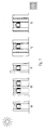
- FIGURE 1 schematically represents the peripheral portion of the insulated glass in a series of non-exhaustive illustrations of possible combinations: 1A normal, 1B triple glass, 1C stepped glass, 1D external laminated glass with internal low-emissive glass, 1E external tempered reflective glass with low-emissive internal laminated glass.
- the two types of sealant materials used are highlighted: in black the butyl sealant that has airtight proprieties (first sealing), and with the dotted line, the polysulphide, polyurethane or silicone sealant which has the propriety of mechanical resistance (second sealing).
- the internal/external direction is visibly identified with icons, which represent the sun (external side), and the heating element (internal side).
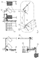
- FIGURE 2 represents a semi-automatic version of the group of machines, indicated with double capital letters: [PB] form the English 'Profile-Bender' (automatic profile bending machine); [DF] from the English 'Desiccant Filler', (machine for filling frames with hygroscopic material); [MB] from the English 'Manual Butyliser' (automatic butyl sealant applying machine); [IL] from the English 'Insulating Glass Line' (Insulating glass manufacturing line).
- the frame is transferred by means of an automatic unloader [au] which feeds a truck conveyor [tc] (which holds the frame in correspondence to one of its right angles), this last one being pushed manually by the operator until it locks into the automatic loader applied to the desiccant filler [DF].
- the frame is transferred by means of the overhead conveyor [oc] (which supports the frame along one of its right angles) and from which the operator using the manual butyliser withdraws the frame for its subsequent butylising process.
- the frame is transferred by means of an overhead conveyor [oc] (which supports the frame in correspondence to one of its right angles) onto which the operator of the manual butyliser hangs the frame and from which the operator from the production line for the insulating glass [IL] withdraws the frame for its subsequent manual positioning on the production line by applying it directly onto the glass sheet onto which the spacer frame remains perfectly adhered.
- an overhead conveyor [oc] which supports the frame in correspondence to one of its right angles
- FIGURE 3 represents a completely automatic version of the group of machines, indicated with double capital letters: [PB] form the English 'Profile-Bender' (automatic profile bending machine); [DF] from the English 'Desiccant Filler', (machine for filling frames with desiccant material); [MB] from the English 'Manual Butyliser' (automatic butyl applying machine); [IL] from the English 'Insulating Glass Line' (Insulating glass manufacturing line).
- the frame is transferred by means of an automatic unloader [au] which (eventually) feeds the truck conveyor (which supports the frame in correspondence to one of its right angles) which moves automatically on track guides until it locks with the automatic loader [al] of the desiccant filler [DF].
- the frame is transferred by means of an overhead conveyor [oc] (which supports the frame in correspondence to one of its right angles) to the automatic loader [al] in correspondence to the automatic butyliser [AB].
- FIGURE 4 represents the constructive details of the mechanisms which apply to the inventive idea of this invention, (referring to the station [DF]) that is, by holding the spacer frame [1] suspended in correspondence to one of its right angles and secured thanks to the sole action of the force of gravity (with spacer frame, the range of spacer frames [1] is intended) .
- the base plate [P] is equipped with an arched-form grille which permits the same base plate [P] to rotate without interfering with the fixed pin [4.1] which runs across it. Subsequently, the base plate which supports the pins [P] rotates around its axis [A] sending the pin 4.5 against the extrados of the frame and the pins [4.2], [4.3] and [4.4] against the intrados of the frame; this last frame therefore finds itself in contrast with the series of pins [4.2], [4.3], [4.4] and [4.5] due to its weight and therefore remains solidly fixed (together with all the other frames [1] to form a consecutive range) in all the subsequent operations such as transport, the transfer and the correct coupling (of one frame at a time) to the machine, for example the desiccant filler [DF].
- the base plate which supports the pins [P] rotates around its axis [A] sending the pin 4.5 against the extrados of the frame and the pins [4.2], [4.3] and [4.4] against the
- the invention hereby presented is liable to numerous and accomplishable variations (with respect to what can be recovered form the designs) which all come within the inventive idea formed by the supporting aspect of the spacer frames, these variations can concern the means of working which can be either electric, electro-electronic, pneumatic, hydraulic and/or combined, etc., the means of control which can be electronic or fluidic and/or combined, etc.
- the constructive details can be substituted with other technically equivalent.
- the materials and the dimensions can be any type according to requirements in particular deriving from the frame types and dimensions.
- the field of application can include not only the spacer frame field for insulated glass panels but any field where the issue is that of moving or transferring objects having a framed shape.
- a protective structure be it of the type which safeguards the mechanical parts, be it of the optical barrier type or tread-sensible mats, etc., in that particular attention is paid, other than to the functional and ergonomic aspects, which are part of the contents of this invention, also to health and safety aspects.
Abstract
An essential feature of the devices is formed by the particular way in which the same frames are handled in every phase during its conveying process, while taking into consideration the spacer frame's aspects of lightness, deformity and variety of dimension.
Description
- Nowadays it is known of: the automatic machine to produce the spacer frame by means of bending, the automatic machine to fill the hollow part of the spacer frame with hygroscopic material, the automatic or semi-automatic machine for applying the butyl sealant to each side face of the spacer frame, the insulating glass manufacturing line. The transfer of the spacer frame from one machine to the other (in other instances it can also be referred to as from one station to another) is so far achieved with totally manual procedures, to the point of even having to handle every single spacer frame in certain cases or in certain phases, or at the most automatically only for the conveying phases from the automatic butyl extruder to the insulating glass manufacturing line.
- In order to better understand the configuration and the function of the spacer frame, we hereby summarise a few notions regarding the product, i.e., the 'spacer frame', and the semi-finished product 'insulated glass' for the which the spacer frame is a part of, deeming the subsequent use of the 'insulated glass' as understood, that is, as a component of door/window fastenings.
- The 'insulated glass' is formed by bonding two or more glass sheets separated by one or more hollow frames presenting micro-holes on the inner face of the frames, the same spacer frames containing hygroscopic material within the hollow part and the chamber (or chambers) which is/are confined by the glass sheets or spacer frame (or frames) which can either contain air or gas or a mixture of gases which confer to the 'insulated glass' particular properties, such as, for example thermal insulating and/or noise insulating. The bonding between glass and spacer (or spacers) is obtained by two levels of sealing, the first being that of creating air-tightness (and also useful for the manufacture of insulated glass), the second having the function of creating the cohesion between the components and mechanical resistance of the bond between the same.
- The glass sheets used in the forming of insulated glass can present different conformations according to the use of the same, for example the outer glass sheet can be either normal or reflective (in order to limit thermal absorption during the Summer months, or laminated/armoured (for those cases against intrusion or vandalism), or laminated/tempered glass (for safety use) or combined (for example reflective and laminated to obtain a combination of the properties), the internal glass sheet can be either normal or low-emissive (to limit heat dispersion during the Winter months) or laminated/tempered (for safety functions) or combined (for example low-emissive and laminated to obtain a combination of properties).
- From the basic summary thus laid out, and which prevailingly refers to the 'spacer frame' as such and of which the global transfer is the subject of this invention which forms part of this request, it is already evident that a manufacturing line requiring to obtain the 'insulated glass' product (normally rectangular in shape yet not excluding any other shapes) requires many consecutive working phases and that production is increased if these phases and the transfer of the manufactured items from one station to another are carried out automatically.
- The procedures for the manufacture of 'insulated glass', each one requiring a relative yet particular machine to be placed in series in respect to other complementary machines are as follows (in order to offer a non-exhaustive example and which at the same time denotes these machines as not all being all necessary):
- EDGE-DELETING: on the boundary edge of the glass should there be any coating on the glass to permit and maintain the adhesive characteristics of the sealant in time.
- WASHING: of each single glass, alternating internal with external glass.
- Electronically automated or visual semi-automatic QUALITY CONTROL.
- SPACER FRAME APPLICATION: the frame which has been previously formed, filled with hygroscopic material and treated to an adhesive sealant to each side of the frame for adhesion, in separate machines in respect to the 'insulating glass' manufacturing line (and purposefully for the transfer of the spacer frame from one station to another is the subject which this request refers to for industrial right of patent) is applied manually, in almost all the machinery, on one of the glass sheets which form the 'insulated glass' on a determined station of the 'insulated glass' manufacturing line.
- COUPLING AND PRESSING of the whole glass/spacer frame.
- FILLING WITH GAS of the chamber (or chambers) which has/have been thus formed.
- APPLICATION OF SEPARATING PADS (packing components).
-
- The above-mentioned procedures, which can be, carried out by each respective machine either automatically or semiautomatically.
- The research of previous state of art patented or however disclosed in pertaining fields or similar to the handling of the spacer frames for their transfer has brought to light the following findings which are therein described. In the field of the semi-automatic machines the patent ref. US 4,912,837 is known with priority to the German 3740922 dated 03.12.87, registered under Franz Xavier Bayer Isolierglasfabrik KG. Not so much the finding but the actual machine which has been built by the proprietor explains that the management of this machine, which proceeds to the filling of the spacer frame with hygroscopic material, can be optimised by equipping the same with: an accumulating store of frames to be filled while feeding the same and of an accumulating store of the filled frames at the unloading point of the same. In the field of the automatic machines it is known of devices which transfer the spacer frames from the machine which automatically applies the adhesive sealant to the two sides of the frame, to the insulated glass manufacturing line, these devices achieving furthermore, subsequently and automatically the application of the spacer frame to the glass in transit and while idle on the insulating glass manufacturing line.
- The research for other known techniques, although included in a technological field as crowded as that of machines and insulating glass manufacturing lines, has not brought to light anything similar to the subject of the current invention, not even during exhibitions which are numerous and recurrent throughout the World, where, ritually, every new-finding and relative machines are put on show.
- The only major issues inherent to the techniques explained above are the following:
- For the desiccant filling machine: no complete exclusion of the operator's intervention and limited capacity of the feeding and unloading stores (such as in the case of the Bayer machine)
- For the machine that applies the frame onto the glass and the
relative transferring device from the butyliser machine:
- 1. Excessive complication of the automation with consequent inconsiderate costs even for the medium-large glass factory and in any case unsatisfactory quality of the final result in that the application of the frame along the edge of the glass requires its positioning in reference to the external edge of the glass with restricted tolerances and therefore out of proportion in respect to the dimensions of the spacer frame; 2. Difficulty in the automated mechanical handling of the same spacer frame in that the handling of the spacer frames occurs along a good part of the extension of the sides and therefore depends on the dimension of the spacer frames.
- The principal task which is the subject of this request is therefore that of resolving the technical problems which have been highlighted by excluding the inconveniences noted in the state of art aforementioned and therefore contriving a device or better still a series of devices or a system which achieves the transfer of the spacer frame for insulated glass from one working station to another along its path, in an automatic, simple, safe and economical fashion, from the machine which bends the frame to the machine which is dedicated to the filling of hygroscopic material to the machine which applies the sealant, to the insulated glass manufacturing line.
- Furthermore, a combination of these devices, in an option, even if wider articulated, allows for the handling and the transfer of spacer frames having different shapes to the rectangular ones, as long as these have at least one right angle.
- To better understand the philosophy of the machine, subject of this invention, the types of products that can be worked and the sequence of the working phases to obtain these results have already been described earlier.
- Let us observe how, with the system of devices included in this application, the transfer of spacer frames for insulating glass between multiple working stations is carried out, these stations including, as neither an exhaustive nor binding example of the types and quantities of these stations, a machine which forms the spacer frame starting from a linear bar to obtain a closed frame by means of bending and/or calendering, a machine which fills the hollow part of the frame with hygroscopic material, a machine which applies the sealant to the sides of the frame and lastly an insulating glass manufacturing line.
- The essential feature of the system of devices is that of having contrived particular mechanisms for supporting and transferring, as well as feeding the station or the machine whose device is interfaced as well as the transfer between one machine and the other, acting on one of the frame's right-angles and taking advantage of the force of gravity to secure it.
- To better describe a method of implementing the invention, and which also includes all its equivalents, the following figures may be commented, relative to two of its essential conformations, without barring possible alternative configurations using the same inventive principle, listing with the same succession of components included in the figures, the phases of the working cycle of the system's devices.
- FIGURE 1 schematically represents the peripheral portion of the insulated glass in a series of non-exhaustive illustrations of possible combinations: 1A normal, 1B triple glass, 1C stepped glass, 1D external laminated glass with internal low-emissive glass, 1E external tempered reflective glass with low-emissive internal laminated glass. The two types of sealant materials used are highlighted: in black the butyl sealant that has airtight proprieties (first sealing), and with the dotted line, the polysulphide, polyurethane or silicone sealant which has the propriety of mechanical resistance (second sealing). This is to understand how important the function of the spacer frame is, mainly rectangular in shape but without excluding any other shapes, as an essential part of the 'insulating glass' and therefore its manufacturing cycle as well as its handling or better its transfer, subject of this request of industrial patent-right. The internal/external direction is visibly identified with icons, which represent the sun (external side), and the heating element (internal side).
- FIGURE 2 represents a semi-automatic version of the group of machines, indicated with double capital letters: [PB] form the English 'Profile-Bender' (automatic profile bending machine); [DF] from the English 'Desiccant Filler', (machine for filling frames with hygroscopic material); [MB] from the English 'Manual Butyliser' (automatic butyl sealant applying machine); [IL] from the English 'Insulating Glass Line' (Insulating glass manufacturing line).
- These machines are connected to each other by means of a group of devices, which form part of this invention, indicated with double small letters: [au] from the English 'Automatic Unloader' (automatic unloading machine); [tc] from the English 'Truck Conveyor' (conveying unit); [oc] from the English 'Overhead Conveyor' (overhead transporting system); some of which require manual operation, others which operate automatically, which carry out the transfer of frames from one working station to another working station. For example, between [PB] and [DF] the frame is transferred by means of an automatic unloader [au] which feeds a truck conveyor [tc] (which holds the frame in correspondence to one of its right angles), this last one being pushed manually by the operator until it locks into the automatic loader applied to the desiccant filler [DF]. Between [DF] and [MB] the frame is transferred by means of the overhead conveyor [oc] (which supports the frame along one of its right angles) and from which the operator using the manual butyliser withdraws the frame for its subsequent butylising process. Between [MB] and [IL] the frame is transferred by means of an overhead conveyor [oc] (which supports the frame in correspondence to one of its right angles) onto which the operator of the manual butyliser hangs the frame and from which the operator from the production line for the insulating glass [IL] withdraws the frame for its subsequent manual positioning on the production line by applying it directly onto the glass sheet onto which the spacer frame remains perfectly adhered.
- FIGURE 3 represents a completely automatic version of the group of machines, indicated with double capital letters: [PB] form the English 'Profile-Bender' (automatic profile bending machine); [DF] from the English 'Desiccant Filler', (machine for filling frames with desiccant material); [MB] from the English 'Manual Butyliser' (automatic butyl applying machine); [IL] from the English 'Insulating Glass Line' (Insulating glass manufacturing line).
- These machines are connected to each other by a group of devices, indicated with double small letters: [au] from the English 'Automatic Unloader' (automatic unloading machine); [tc] from the English 'Truck Conveyor' (conveying unit); [al] from the English 'Automatic Loader' (automatic loading machine); [oc] from the English 'Overhead Conveyor' (overhead transporting system); all machines working automatically, which carry out the transfer of frames from one working station to another working station. For example, between [PB] and [DF], the frame is transferred by means of an automatic unloader [au] which (eventually) feeds the truck conveyor (which supports the frame in correspondence to one of its right angles) which moves automatically on track guides until it locks with the automatic loader [al] of the desiccant filler [DF]. Between [DF] and [AB] the frame is transferred by means of an overhead conveyor [oc] (which supports the frame in correspondence to one of its right angles) to the automatic loader [al] in correspondence to the automatic butyliser [AB]. Between [AB] and [IL] the frame is transferred by means of an overhead conveyor [oc] (which supports the frame in correspondence to its right angle) which withdraws the frame from the automatic unloader [au] of the automatic butyliser [AB] to take it to the automatic loader [al] of the insulating glass manufacturing line [IL].
- FIGURE 4 represents the constructive details of the mechanisms which apply to the inventive idea of this invention, (referring to the station [DF]) that is, by holding the spacer frame [1] suspended in correspondence to one of its right angles and secured thanks to the sole action of the force of gravity (with spacer frame, the range of spacer frames [1] is intended) . This is obtained by first supporting the frame [1] (or better the range of frames [1]) in correspondence to its square angle by means of the isolated pin [4.1], in this phase the remaining pins [4.2], [4.3] and [4.4] which are all fixed to the base plate [P], hinged on the axis [A], are within the frame yet far from the internal wall while pin 4.5, which is also fixed to the base plate [P] is in the proximity of the external wall of the frame yet far from the same external wall.
- The base plate [P] is equipped with an arched-form grille which permits the same base plate [P] to rotate without interfering with the fixed pin [4.1] which runs across it. Subsequently, the base plate which supports the pins [P] rotates around its axis [A] sending the pin 4.5 against the extrados of the frame and the pins [4.2], [4.3] and [4.4] against the intrados of the frame; this last frame therefore finds itself in contrast with the series of pins [4.2], [4.3], [4.4] and [4.5] due to its weight and therefore remains solidly fixed (together with all the other frames [1] to form a consecutive range) in all the subsequent operations such as transport, the transfer and the correct coupling (of one frame at a time) to the machine, for example the desiccant filler [DF].
- The descriptions mentioned above refer to a system of devices where the flow has a direction which is represented in the figure; it is easy to imagine a description and relative figures which refer to a symmetrical flow or however, different.
- Obviously all the interconnected movements of the system of devices are inter-locked between themselves, in aid of a logical parallel however, always active, in order to avoid any conditions of interference between the spacer frame and parts of the mechanisms.
- The invention hereby presented is liable to numerous and accomplishable variations (with respect to what can be recovered form the designs) which all come within the inventive idea formed by the supporting aspect of the spacer frames, these variations can concern the means of working which can be either electric, electro-electronic, pneumatic, hydraulic and/or combined, etc., the means of control which can be electronic or fluidic and/or combined, etc.
- The constructive details can be substituted with other technically equivalent. The materials and the dimensions can be any type according to requirements in particular deriving from the frame types and dimensions.
- Furthermore the field of application can include not only the spacer frame field for insulated glass panels but any field where the issue is that of moving or transferring objects having a framed shape.
- The system of mechanisms, where the same are found close to the operator, is equipped with a protective structure, be it of the type which safeguards the mechanical parts, be it of the optical barrier type or tread-sensible mats, etc., in that particular attention is paid, other than to the functional and ergonomic aspects, which are part of the contents of this invention, also to health and safety aspects.
Claims (9)
- Device or system of automatic devices for the transfer of spacer frames [1] for insulating glass between multiple stations or manufacturing machines characterised in that the mechanisms [4.1], [4.2], [4.3], [4.4] and [4.5] apt for the support and movement, either to feed the station (or the machine onto which the device is interfaced) or for the transfer between one machine and the other, are acting along one of the spacer frame's right angles.
- Device or system of devices as per claim 1, characterised in that the mechanisms [4.1], [4.2], [4.3], [4.4] and [4.5] for the support and movement of the spacer frame [1] acting along one of the spacer frame's right angles, supports it in part on the internal side and in part on the external side and that the clamping tie between mechanism and frame is supplied by the leverage formed by the same frame which, thanks to the sole force of gravity has a moment of stableness in respect to the supports.
- Device or system of devices as per claim 1, characterised in that the supporting of the spacer frames [1] is overhead in a way that the mechanisms supplied with any movement are at a height over the space where people can stand or transit.
- Device or system of devices as per claim 2 characterised in that the supporting element [4.1] acting on the inner face of the spacer frame [1] and the clamping tie [4.2], [4.3], [4.4] and [4.5] which acts, thanks to the spacer frame's gravity, on the external wall of the side of the frame and have such an extension to support and secure a variety of frames able to form a capacious store for both feeding and unloading from the machine to which the device or system of devices is dedicated.
- Device or system of devices as per claims 1 to 4 characterised in that it operates on spacer frames [1] which are not rectangular in shape yet having at least one right angle.
- Device or system of devices as per the above claims characterised in that the field of application can concern not only the field of spacer frames for insulating glass panels but any field where the issue interests the movement and transfer of objects having a framed shape.
- Device or system of devices as per one or more of the former claims characterised as per descriptions and illustrations in the attached diagrams.
- Automatic or semi-automatic procedure for the transfer of spacer frames [1] for insulated glass between multiple stations or manufacturing machines characterised in that the mechanisms [4.1], [4.2], [4.3], [4.4] and [4.5] apt for the supporting and the movement, either to feed the station (or the machine onto which the device is interfaced) or for the transfer between one machine and the other, are acting along one of the spacer frame's right angles.
- Automatic or semi-automatic procedure as per claim 8 characterised in that the mechanisms [4.1], [4.2], [4.3], [4.4] and [4.5] for the support and movement of the spacer frame [1] acting along one of the spacer frame's right angles, supports it in part on the internal side and in part on the external side and that the clamping tie between mechanism and frame is supplied by the leverage formed by the same frame which, thanks to the sole force of gravity has a moment of stableness in respect to the supports.
Applications Claiming Priority (2)
| Application Number | Priority Date | Filing Date | Title |
|---|---|---|---|
| ITTV000131 | 2000-10-20 | ||
| IT2000TV000131 IT1316541B1 (en) | 2000-10-20 | 2000-10-20 | SYSTEM OF AUTOMATIC DEVICES FOR THE TRANSFER OF TELE-SPACERS FOR GLASS BETWEEN MANY WORKING STATIONS. |
Publications (2)
| Publication Number | Publication Date |
|---|---|
| EP1199437A2 true EP1199437A2 (en) | 2002-04-24 |
| EP1199437A3 EP1199437A3 (en) | 2003-01-22 |
Family
ID=11459920
Family Applications (1)
| Application Number | Title | Priority Date | Filing Date |
|---|---|---|---|
| EP01124668A Withdrawn EP1199437A3 (en) | 2000-10-20 | 2001-10-16 | Automatic system of devices for insulating glass spacer frame transfer between multiple processing stations |
Country Status (2)
| Country | Link |
|---|---|
| EP (1) | EP1199437A3 (en) |
| IT (1) | IT1316541B1 (en) |
Citations (1)
| Publication number | Priority date | Publication date | Assignee | Title |
|---|---|---|---|---|
| US4912837A (en) | 1987-12-03 | 1990-04-03 | Franz Xaver Bayer Isolierglasfabrik Kg | Method of and apparatus for making spacer frames for use in multiple-pane windows |
Family Cites Families (1)
| Publication number | Priority date | Publication date | Assignee | Title |
|---|---|---|---|---|
| DE4438502C1 (en) * | 1994-10-28 | 1996-02-08 | Fr Xaver Bayer Isolierglasfabr | Transfer arrangement for clearance maintenance frames |
-
2000
- 2000-10-20 IT IT2000TV000131 patent/IT1316541B1/en active
-
2001
- 2001-10-16 EP EP01124668A patent/EP1199437A3/en not_active Withdrawn
Patent Citations (1)
| Publication number | Priority date | Publication date | Assignee | Title |
|---|---|---|---|---|
| US4912837A (en) | 1987-12-03 | 1990-04-03 | Franz Xaver Bayer Isolierglasfabrik Kg | Method of and apparatus for making spacer frames for use in multiple-pane windows |
Also Published As
| Publication number | Publication date |
|---|---|
| EP1199437A3 (en) | 2003-01-22 |
| ITTV20000131A1 (en) | 2002-04-20 |
| IT1316541B1 (en) | 2003-04-22 |
Similar Documents
| Publication | Publication Date | Title |
|---|---|---|
| RU2384686C2 (en) | Method of making of double-glass pane | |
| CA2544872C (en) | A framed panel and related method of manufacture | |
| AU2017249264A1 (en) | Transport bag, conveying device and method for opening or closing a transport bag | |
| CN104508411A (en) | Refrigerator | |
| CZ20023390A3 (en) | Insulating glazing and process for producing thereof | |
| ITTV20080032A1 (en) | AUTOMATIC DEVICE AND AUTOMATIC PROCEDURE FOR PERIMETRAL SEALING OF INSULATING GLASS CONSISTING OF AT LEAST TWO GLASS SHEETS AND AT LEAST ONE FRAME SPACER WITH PROFILE DIFFERENT COMPLEX FROM THE TRADITIONAL. | |
| RU2724866C1 (en) | Method and system for production of windows/doors | |
| CN111659776A (en) | Angle assembling machine for processing curtain wall door and window | |
| EP2121239B1 (en) | System and process for manufacturing framelss windows | |
| US20220372813A1 (en) | Method and device for manufacturing and applying a rigid spacer frame to an insulating glass | |
| KR20040054714A (en) | Insulating glazing and the production method thereof | |
| ITTV20080031A1 (en) | AUTOMATIC DEVICE AND AUTOMATIC PROCEDURE FOR FILLING THE INSULATING GLASS CONSISTING OF AT LEAST TWO GLASS SHEETS AND AT LEAST A SPACER FRAME WITH GAS OTHER THAN AIR. | |
| US20220186552A1 (en) | Insulating glass panels and method and device for assembling said insulating glass panels | |
| EP1199437A2 (en) | Automatic system of devices for insulating glass spacer frame transfer between multiple processing stations | |
| EP1288112B1 (en) | A set of elements for the rapid assembly of truck bodies for means of transport | |
| JP2018515703A (en) | Method for manufacturing a window block element | |
| CN112777044A (en) | Bagging machine | |
| US10890026B2 (en) | Automatic machine for alternable application of a plurality of flexible spacer profiles on a glass sheet | |
| CN105579654B (en) | Conveying device | |
| EP1297901A2 (en) | Automatic machine and procedure for the extrusion and application of sealant onto the lateral walls of a spacer frame for insulated glass | |
| US20220186551A1 (en) | Method and device for assembling insulating glass panels as well as insulating glass panel produced in this way | |
| ATE263105T1 (en) | METHOD AND SYSTEM FOR TRANSFER OF ITEMS FROM A MANUFACTURING UNIT TO A PACKAGING UNIT | |
| ITRM930428A1 (en) | IMPROVED EQUIPMENT FOR THE MANUFACTURE OF INSULATING GLASS FOR CARS. | |
| WO2019001800A1 (en) | Automatic apparatus and automatic method for high-productivity production of the insulating glazing unit constituted by at least two glass sheets and at least one spacer frame | |
| CN213837795U (en) | Automatic glass assembling device and assembling system for unit curtain wall |
Legal Events
| Date | Code | Title | Description |
|---|---|---|---|
| PUAI | Public reference made under article 153(3) epc to a published international application that has entered the european phase |
Free format text: ORIGINAL CODE: 0009012 |
|
| AK | Designated contracting states |
Kind code of ref document: A2 Designated state(s): AT BE CH CY DE DK ES FI FR GB GR IE IT LI LU MC NL PT SE TR |
|
| AX | Request for extension of the european patent |
Free format text: AL;LT;LV;MK;RO;SI |
|
| PUAL | Search report despatched |
Free format text: ORIGINAL CODE: 0009013 |
|
| AK | Designated contracting states |
Kind code of ref document: A3 Designated state(s): AT BE CH CY DE DK ES FI FR GB GR IE IT LI LU MC NL PT SE TR |
|
| AX | Request for extension of the european patent |
Free format text: AL;LT;LV;MK;RO;SI |
|
| 17P | Request for examination filed |
Effective date: 20030714 |
|
| AKX | Designation fees paid |
Designated state(s): AT BE CH CY DE DK ES FI FR GB GR IE IT LI LU MC NL PT SE TR |
|
| AXX | Extension fees paid |
Extension state: SI Payment date: 20030714 |
|
| 17Q | First examination report despatched |
Effective date: 20031016 |
|
| STAA | Information on the status of an ep patent application or granted ep patent |
Free format text: STATUS: THE APPLICATION HAS BEEN WITHDRAWN |
|
| 18W | Application withdrawn |
Effective date: 20040319 |