EP1199622A1 - Bedienungselement - Google Patents
Bedienungselement Download PDFInfo
- Publication number
- EP1199622A1 EP1199622A1 EP01122079A EP01122079A EP1199622A1 EP 1199622 A1 EP1199622 A1 EP 1199622A1 EP 01122079 A EP01122079 A EP 01122079A EP 01122079 A EP01122079 A EP 01122079A EP 1199622 A1 EP1199622 A1 EP 1199622A1
- Authority
- EP
- European Patent Office
- Prior art keywords
- element according
- platform
- control element
- control
- connecting elements
- Prior art date
- Legal status (The legal status is an assumption and is not a legal conclusion. Google has not performed a legal analysis and makes no representation as to the accuracy of the status listed.)
- Granted
Links
- 238000005259 measurement Methods 0.000 claims abstract description 6
- 238000006073 displacement reaction Methods 0.000 claims abstract description 4
- 241000238631 Hexapoda Species 0.000 claims description 23
- 238000005452 bending Methods 0.000 claims description 17
- 238000011156 evaluation Methods 0.000 claims description 16
- 238000010168 coupling process Methods 0.000 claims description 12
- 230000008878 coupling Effects 0.000 claims description 11
- 238000005859 coupling reaction Methods 0.000 claims description 11
- 230000004913 activation Effects 0.000 claims description 7
- 230000008859 change Effects 0.000 claims description 4
- 238000000034 method Methods 0.000 abstract description 3
- 230000006835 compression Effects 0.000 abstract 1
- 238000007906 compression Methods 0.000 abstract 1
- 238000012545 processing Methods 0.000 description 5
- 230000003750 conditioning effect Effects 0.000 description 3
- 238000013461 design Methods 0.000 description 3
- 238000011161 development Methods 0.000 description 3
- 230000018109 developmental process Effects 0.000 description 3
- 230000007246 mechanism Effects 0.000 description 3
- 230000008901 benefit Effects 0.000 description 2
- 238000006243 chemical reaction Methods 0.000 description 2
- 238000012549 training Methods 0.000 description 2
- 230000009466 transformation Effects 0.000 description 2
- 238000013519 translation Methods 0.000 description 2
- 239000013598 vector Substances 0.000 description 2
- 230000003321 amplification Effects 0.000 description 1
- 230000009286 beneficial effect Effects 0.000 description 1
- 230000015572 biosynthetic process Effects 0.000 description 1
- 230000000694 effects Effects 0.000 description 1
- 210000003811 finger Anatomy 0.000 description 1
- 230000006870 function Effects 0.000 description 1
- 230000001939 inductive effect Effects 0.000 description 1
- 238000012986 modification Methods 0.000 description 1
- 230000004048 modification Effects 0.000 description 1
- 238000003199 nucleic acid amplification method Methods 0.000 description 1
- 230000005693 optoelectronics Effects 0.000 description 1
- 239000004033 plastic Substances 0.000 description 1
- 230000004044 response Effects 0.000 description 1
- 239000004065 semiconductor Substances 0.000 description 1
- 210000003813 thumb Anatomy 0.000 description 1
- 238000012546 transfer Methods 0.000 description 1
- 238000000844 transformation Methods 0.000 description 1
Images


Classifications
-
- G—PHYSICS
- G05—CONTROLLING; REGULATING
- G05G—CONTROL DEVICES OR SYSTEMS INSOFAR AS CHARACTERISED BY MECHANICAL FEATURES ONLY
- G05G9/00—Manually-actuated control mechanisms provided with one single controlling member co-operating with two or more controlled members, e.g. selectively, simultaneously
- G05G9/02—Manually-actuated control mechanisms provided with one single controlling member co-operating with two or more controlled members, e.g. selectively, simultaneously the controlling member being movable in different independent ways, movement in each individual way actuating one controlled member only
- G05G9/04—Manually-actuated control mechanisms provided with one single controlling member co-operating with two or more controlled members, e.g. selectively, simultaneously the controlling member being movable in different independent ways, movement in each individual way actuating one controlled member only in which movement in two or more ways can occur simultaneously
- G05G9/047—Manually-actuated control mechanisms provided with one single controlling member co-operating with two or more controlled members, e.g. selectively, simultaneously the controlling member being movable in different independent ways, movement in each individual way actuating one controlled member only in which movement in two or more ways can occur simultaneously the controlling member being movable by hand about orthogonal axes, e.g. joysticks
- G05G9/04737—Manually-actuated control mechanisms provided with one single controlling member co-operating with two or more controlled members, e.g. selectively, simultaneously the controlling member being movable in different independent ways, movement in each individual way actuating one controlled member only in which movement in two or more ways can occur simultaneously the controlling member being movable by hand about orthogonal axes, e.g. joysticks with six degrees of freedom
-
- Y—GENERAL TAGGING OF NEW TECHNOLOGICAL DEVELOPMENTS; GENERAL TAGGING OF CROSS-SECTIONAL TECHNOLOGIES SPANNING OVER SEVERAL SECTIONS OF THE IPC; TECHNICAL SUBJECTS COVERED BY FORMER USPC CROSS-REFERENCE ART COLLECTIONS [XRACs] AND DIGESTS
- Y10—TECHNICAL SUBJECTS COVERED BY FORMER USPC
- Y10T—TECHNICAL SUBJECTS COVERED BY FORMER US CLASSIFICATION
- Y10T74/00—Machine element or mechanism
- Y10T74/20—Control lever and linkage systems
- Y10T74/20012—Multiple controlled elements
- Y10T74/20201—Control moves in two planes
-
- Y—GENERAL TAGGING OF NEW TECHNOLOGICAL DEVELOPMENTS; GENERAL TAGGING OF CROSS-SECTIONAL TECHNOLOGIES SPANNING OVER SEVERAL SECTIONS OF THE IPC; TECHNICAL SUBJECTS COVERED BY FORMER USPC CROSS-REFERENCE ART COLLECTIONS [XRACs] AND DIGESTS
- Y10—TECHNICAL SUBJECTS COVERED BY FORMER USPC
- Y10T—TECHNICAL SUBJECTS COVERED BY FORMER US CLASSIFICATION
- Y10T74/00—Machine element or mechanism
- Y10T74/20—Control lever and linkage systems
- Y10T74/20207—Multiple controlling elements for single controlled element
- Y10T74/20213—Interconnected
Definitions
- the invention relates to an operating element for manual Control of spatial movement sequences of a to be controlled System.
- Operating elements are used to control mechanisms used, for example, one Operating lever or a joystick, which is a or two axes are pivotable. These controls allow control of the mechanism in two Degrees of freedom.
- EP-A-0 981 describes 078 a joystick-like operating lever that is using a universal joint in two directions, forward and can move back and left and right.
- the aim of the present invention is to provide an operating element to get control of more than two and up to six degrees of freedom allowed. Driving to the six Degrees of freedom should be possible at the same time.
- the operator should only be a handle, for example a Control levers that are available to operate all Makes degrees of freedom possible without additional Activation elements must be operated.
- the object underlying the invention is seen in specify an operating element of the type mentioned at the outset, through which the aforementioned problems are overcome and the Goals are achieved.
- a simple, ergonomic operation one control in more than two Degrees of freedom may be possible.
- the control element according to the invention contains a handle, which can be designed as an operating lever and from can be operated by an operator.
- the handle is on attached to a platform so that the platform of movement the handle follows or so that is exerted on the handle Forces are transferred to the platform.
- Between the Platform and a fixed console are at least six Fasteners arranged.
- On the handle forces can preferably be in six degrees of freedom exercise: in three different translational directions and around three different axes of rotation. this leads to Length signals or force signals that the Fasteners are assigned.
- Coordinates and three orientation angles determine which the Location of the platform in relation to the console or which the on the applied force vectors and moment vectors reflect.
- the measuring signals of the position encoder or the Force transducers reflect the position of the handle or on the Manage forces and moments in a clear way contrary.
- Known methods can be used for the calculation of coordinates are used (Hebsacker, M .: The design of the kinematics des Hexaglide - "Methodology for the design of parallel Machine Tools ", VDI Reports No. 1427, 1998).
- the length signals or the force signals are represented by a Evaluation unit evaluated and to control the Movements of the system to be controlled are used. there calculates the evaluation unit from the measured values which the Kinematics of the handle reflect the respective position of the Handle or the forces exerted on the handle and Moments and gives appropriate control signals to the controlling system.
- the control element according to the invention can thus be used for manual Control of spatial movement sequences of a to be controlled System, for example a virtual system, be used. It can be done with just one Control element a control of spatial movements of a system to be controlled in up to six degrees of freedom without additional switches and the like must be operated. The control can thus be simple and done ergonomically.
- Hexapods are basic are known and are used, for example, in measuring devices Checking the position accuracy of machine tools (DE-A-35 04 464), for motorized coordinate measuring machines (DE-A-197 20 049) and used in robot kinematics.
- machine tools DE-A-35 04 4614
- motorized coordinate measuring machines DE-A-197 20 049
- robot kinematics Under hexapod an arrangement of connecting elements is to be understood, which enables movements in six degrees of freedom.
- the hexapod can have six or more (for example eight) fasteners contain.
- the handle can be moved laterally in two directions, for example swivel, twist around its axis, laterally in two Shift directions and out in the direction of their axis Push. If force sensors are used, the movements of the handle must be so small that they Operator are not noticed. In this case the operator for setting control commands does not carry out a certain spatial adjustment of the handle, but exert forces on the handle that the desired Control signals. Such a versatile activity a handle is with the previously known controls not possible.
- the invention can be used for the control of mechanisms Use more than two degrees of freedom.
- a preferred one Use case arises in connection with a Attachment interface for coupling work tools to a Work vehicle, as it is in the subsequently published DE-A-199 51 840 is described.
- With the mounting interface described there are six between a tractor body and a coupling frame Hydraulic cylinders arranged in the manner of a hexapod intended.
- These hydraulic cylinders can by Control element according to the invention can be controlled by the signals of each encoder or force transducer Operating hexapods for controlling a corresponding one Hydraulic cylinder of the add-on interface hexapod becomes.
- control element as a so-called "three-dimensional mouse” is used and the control serves virtual spatial movements, for example can be made visible on a screen.
- each telescopic leg contains two longitudinally displaceable relative to each other Telescopic rods, the free ends of which can be pivoted on all sides Attack platform or on the console, the Attack points in the area of the corner points of a triangle can lie.
- the telescopic legs are with position encoders equipped, the length signals of the respective length of the corresponding telescopic leg correspond.
- Each telescopic leg can be one to both, for example Have open cylinder housing on each side Side holds a sliding telescopic rod.
- the Telescopic rods are held in their central position by springs supported. By actuating the operating lever against the force of the springs can be the lengths of the struts change. When the operating lever is released, the Platform and with it the operating lever in the middle position back.
- the Telescopic rods also each have a friction seat in the Cylinder housing to be guided, so that for a Longitudinal displacement friction forces must be overcome.
- the position encoders can be ohmic Act sliding resistors. However, it is also possible for example inductive, capacitive or optoelectronic To use displacement transducers.
- the connecting elements in their longitudinal extent in are essentially rigid so that they can be exercised axial forces are neither longer nor shorter.
- force transducers measured. For example, come as a force transducer Strain gauges or piezoelectric sensors.
- the attachment points on the platform and / or on the console are preferably approximately in the range the corners of an equilateral triangle.
- two connecting elements are articulated near each corner, and can be given away in two directions. It can However, it should also be appropriate to the articulation points in about Corners of a rectangle or a hexagon or in another arrange geometric figure. With a square you can for example, two connecting elements on two attack adjacent corners of the square, and one each or two each of the other connecting elements to the other two corners of the square.
- the connecting elements rigidly on the console too attach and articulate to the platform.
- one for each of the articulated connections or more rubber-like elements used that have a side Tilting of the connecting elements in relation to the platform allow, but are sufficiently rigid to pull and To transmit pressure forces.
- a particularly preferred development of the invention provides before that the platform contains bending elements, each of which attacks a rigid connecting element and which or bend momentary loads on the handle.
- the bending elements are preferably rod or tab-shaped trained and rigid with at least one end with the Platform connected. They are transverse to the longitudinal extension of the Fasteners aligned. The term crosswise closes in addition to a right-angled formation also other angles between the orientations of the bending element and the Connecting element. These are expediently Bending elements with only one of their ends with the platform connected and stand laterally with their other, free end from the platform.
- each Attack fastener it is advantageous in the area the corner each formed two or more as a bending element side by side and essentially parallel to each other to provide running rods or tabs.
- the tabs can be, for example form such that the platform slits in its corners and the slots essentially to the center of the platform are aligned.
- a bending element e.g. a tab
- the Area between the attachment point of the connecting element and the central area of the platform is essentially in radial direction, i.e. towards the center of the platform Strain gauges arranged.
- top and bottom are called surfaces of the bending element, which in essentially transverse to the longitudinal extension of the connecting elements run.
- Temperature compensation and signal amplification To achieve (doubling), it is beneficial to both on the Top as well as on the bottom of a bending element each to arrange at least one strain gauge.
- the two Strain gauges are connected to form a half bridge.
- the Half bridge can be integrated into a full bridge within the amplifier complete and provide an output signal in the form of a Bridge imbalance.
- the bridge voltage can be fed to a measuring amplifier which is integrated in a microcontroller.
- a measuring amplifier which is integrated in a microcontroller.
- the microcontroller can also do the whole Take over geometry calculation. It calculates the output signals into force and moment components and passes this data on a bus line, for example a CAN bus.
- the absolute The value of each force and moment component is a measure of that The speed at which the system to be controlled is moving should.
- the directions of the forces give the direction of the Translation and the direction of the moments give the direction of the System rotation.
- the evaluation electronics can be integrated Have semiconductor elements as it is for printing and Accelerometers is common.
- the type Training angle lever in which one leg, for example protrudes vertically from the platform and the other free, in essentially right-angled legs approximately parallel runs to the platform.
- the free leg is in his unactuated rest position upwards and can be Operator comfortably within six degrees of freedom actuate.
- control element further increasing of the invention in the area of the free end of the handle arranged at least one control element. It is about for example, one with a finger or the Thumb operated switch or push button through which a electrical switch is operated, or to a role that is connected to an electrical analog encoder. It can also an activation flap can be mounted on the handle, such as it was described for example in DE-A-0 981 078.
- Such controls allow security requirements fulfill and control other functions without that the operator remove their hand from the handle got to.
- the control can be in the Functionality should be integrated that is to be controlled System can only be moved by operating the handle, if an operating switch integrated in the handle is operated. This allows an unintended one Actuation of the system to be controlled, e.g. B. while driving, avoid.
- the output characteristic of the evaluation unit preferably depends on non-linearly from the measured tensile or compressive forces so that with a linear increase in bending force a non-linear operating speed for the system to be controlled is specified.
- By influencing the Output characteristic there is also the possibility of giving the system a To give response threshold.
- the six measurement variables can be transformed through coordinate transformations Forces or paths in any spatial Coordinate system can be calculated.
- the force sizes in the main axis directions of the handle determine.
- the movement quantities e.g. Target speeds in the respective directions
- a possible area of application on which the control element according to the invention the operation can be easier is to control one as a hexapod trained system, for example the Hexapod system of Attachment device of a work vehicle.
- the geometry of the control element hexapods to adapt to the geometry of the system hexapods so that this are similar to each other.
- the length dimensions and Articulation points of the telescopic legs in a fixed ratio to the length dimensions and articulation points of the drive elements of the system hexapods, so the kinematics of the two Hexapod arrangements are similar or identical to each other.
- the operator can thus the coupling triangle from the vehicle position Operate as desired to carry out coupling processes or that to move the attached device as required.
- the control element can e.g. B. also the control of a vehicle power lift, for example, a front linkage.
- Control element according to the invention is in the Vehicle control, in which the control element of the control serves a vehicle component.
- the console of the control element part of a vehicle console is in particular part of the vehicle position.
- the operating lever 12 is a joystick-like on a platform 10
- Operating lever 12 attached, which is not in its actuated rest position.
- the operating lever 12 has two legs running essentially perpendicular to each other 14, 16, of which a first leg 14 essentially protrudes vertically from the platform 10 and a second leg 16 is angled upwards.
- the second leg 16 is a ergonomically designed control handle and leaves one convenient operation too.
- the platform 10 is essentially an equilateral triangle formed with one corner of the triangle at the top. Approximately in the area of each corner of this triangle two grab each Telescopic legs 18, 20, 22, 24, 26, 28 formed connecting elements on. The other ends of the telescopic legs 18, 20, 22, 24, 26, 28 are only partially on one shown vehicle console 30 articulated, the Articulation points also essentially an equilateral Form a triangle, but around the platform triangle Is rotated 60 ° so that one corner of this triangle is below lies. The articulation points between the telescopic legs 18, 20, 22, 24, 26, 28 and platform 10 or console 30 pivoting of the telescopic legs 18, 20, 22, 24 on all sides, 26, 28 to.
- the telescopic legs 18, 20, 22, 24, 26, 28 are like one Hexapods between platform 10 and console 30 arranged.
- Each telescopic leg contains 18, 20, 22, 24, 26, 28 two axially displaceable Telescopic rods and one not shown Position encoder, which determines the relative position between the two Articulation points of the telescopic leg 18, 20, 22, 24, 26, 28 detected and corresponding length signals to an evaluation unit 32 emits.
- a side Control element in the form of a pressure switch 33 (Activation button) arranged on the second leg 16 of the operating lever 12 .
- a pressure switch 33 Activation button
- the Attachment interface 36 includes a coupling frame 38 Hook 40 for fastening not shown Implements. Between the coupling frame 38 and the Tractor body 42 extends six hydraulic cylinders 44, 46, 48, 50, 52, 54, arranged in the manner of a hexapod and be operated. The spatial linkage of the hydraulic cylinders and their length dimensions are fixed Proportional ratio to the spatial articulation points and Length dimensions of the telescopic legs 18, 20, 22, 24, 26, 28 des Control element 34.
- the Activation determines the evaluation device 32 the measured value each encoder and gives proportional control signals to the hydraulic cylinders 44, 46, 48 corresponding to the position sensors 50, 52, 54 from. For example, the measurement signal of the Telescopic legs 20 through the evaluation device 32 in one Control signal for the hydraulic cylinder 46 converted.
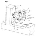
- FIG. 3 shows an alternative embodiment to that of FIG Control element out.
- the one in between triangular platform 60 and a mounting plate 62 arranged connecting elements are not telescopic here formed, as shown in Fig. 1. Rather, it is about 3 around rigid connecting rods 64, 66, 68, 70, 72, 74. Similar to FIG. 1, the connecting rods 64, 66, 68, 70, 72, 74 in the corner area of equilateral triangles arranged. However, they are rigid with the mounting plate connected and stand with the platform via a rubber element 76, which forms an articulated connection.
- each tab 80 In the area of the three corners of the platform 60 there are two each formed parallel to each other tabs 80, the are separated from each other by a slot 82.
- the Tabs 80 and slots 82 are towards the center of platform 60, So aligned to handle 78.
- the tabs 80 are each one end of a connecting rod 64, 66, 68, 70, 72, 74 with the interposition of a rubber element 76 attached.
- each tab 80 an upper strain gauge 84 attached.
- the Strain gauges 84 are parallel to the tabs 80 with their Longitudinal alignment towards the center of the platform.
- the Strain gauges 84 are in a region of the respective tab 80 arranged between the rubber element 76 and that of End of the slot 82 facing the center of the platform. forces when a handle 80 is actuated by a tab 80 on the associated rigid connecting rod 64, 66, 68, 70, 72, 74 exercised lead to a corresponding bending the tab 80 up or down and thus one corresponding change in resistance of the strain gauge 84.
- each tab 80 On the opposite side of the visible platform The back of each tab 80 is opposite the top Strain gauges 84 each have a lower one, not in FIG. 3 Strain gauge 86 visible but shown in FIG. 4.
- a front strain gauge 84 and a rear strain gauge 86 are connected together in a half bridge.
- the half bridge is supplemented by three supplementary resistors 88, 90, 98 to form a full bridge.
- the resistor 98 is an adjustable resistor, through which a manual, rough zero adjustment of the bridge circuit can be carried out.
- a bridge supply voltage U S is applied to the strain gauges 84, 86 connected in series.
- the bridge provides a bridge voltage U B in the form of a bridge detuning at a center tap between the two strain gauges 84, 86 on the one hand and at a center tap between the two supplementary resistors 88, 90 on the other hand.
- the arrangement of the strain gauges 84, 86 in a bridge circuit results in temperature compensation between the front and rear of the platform 60.
- the use of two strain gauges 84, 86 per tab 80 further doubles the output signal compared to only one strain gauge.
- the bridge voltage U B is amplified by a measuring amplifier 92 and then fed to an input signal processor 94.
- the input signal conditioning 94 is connected to a zero adjustment device 96.
- the zero compensation device can be a corresponding program part.
- the integrated zero adjustment allows drifts of the measuring amplifier 92 as well as small plastic changes in the system or voltage fluctuations to be automatically compensated.
- the automatic zero adjustment is only carried out when the operating element is not to be operated and therefore an activation switch arranged on the operating handle 78 is not operated.
- the output voltage U A of the input signal conditioning 94 is a measure of the force in the respective connecting rod 64, 66, 68, 70, 72, 74.
- An output voltage U A is provided for each pair of strain gauges 84, 86.
- the output voltages U A of all pairs of strain gauges 84, 86, of which only one was shown in FIG. 4, are fed to a geometry calculation unit 100, by means of which the measurement signals are converted into force and moment components.
- the force components F x , F y and F z and the moment components M x , M y and M z are calculated in the usual way by coordinate transformation from the respective geometry (direction) of the connecting rods 84, 86, 88, 90, 92, 94 and the force measured values of the strain gauges 84, 86.
- force F x in the x direction force F y in the y direction
- force F z in the z direction moment M x about the x axis
- moment M y around the y axis moment M z around the z axis.
- the magnitude of the forces is a measure of the speed at which the system to be controlled is to be moved, while the direction of the forces reflects the direction of translation and the direction of the moments reflect the direction of rotation of the system.
- the output signals of the geometry calculation unit 100 are in an output signal processing 102, which with a Characteristic curve memory 104 is connected in accordance with the provided characteristics of a non-linear conversion subjected and to a via a plug, not shown CAN bus 106 output.
- a Characteristic curve memory 104 is connected in accordance with the provided characteristics of a non-linear conversion subjected and to a via a plug, not shown CAN bus 106 output.
- strain gauges 84, 86 Supplementary resistors 88, 90, 98 amplifier 92, Input signal conditioning 94 and zero balancing devices 96 are together with the geometry calculation unit 100, the Output signal processing 102 and the characteristic curve memory 104 combined into a common integrated component 108.
- This component 108 is preferably on the Back of the platform 60 attached. However, it can also be appropriate, the component 108 in an external Housing the controller housing.
Abstract
Description
- Fig. 1
- die perspektivische Darstellung eines ersten erfindungsgemäßen Bedienungselements, das an einer Fahrzeugkonsole montiert ist,
- Fig. 2
- die Heckansicht eines Traktors mit einer Anbauschnittstelle zur Kopplung von Arbeitsgeräten und einem erfindungsgemäßen Bedienungselement,
- Fig. 3
- die perspektivische Darstellung eines zweiten erfindungsgemäßen Bedienungselements, das auf einer Befestigungsplatte montiert ist, und
- Fig. 4
- eine elektrische Schaltungsanordnung für die Messsignalverarbeitung.
Claims (22)
- Bedienungselement zur Ansteuerung räumlicher Bewegungsabläufe eines zu steuernden Systems (36)mit einer von einer Bedienungsperson betätigbaren an einer Plattform (10, 60) befestigten Handhabe (12, 78),mit wenigstens sechs zwischen der Plattform (10, 60) und einer feststehenden Konsole (30, 62) angeordneten Verbindungselementen (18, 20, 22, 24, 26, 28; 64, 66, 68, 70, 72, 74),mit Wegmessgebern zur Erfassung der Längenänderung der Verbindungselemente (18, 20, 22, 24, 26, 28) und/oder mit Kraftmessgebern (84) zur Erfassung der in den Verbindungselementen (64, 66, 68, 70, 72, 74) wirkenden Zug- und Druckkräfte, undmit einer Auswerteeinheit (32, 108) zur Auswertung der Messsignale und zur Bereitstellung von Ansteuersignalen für die räumlichen Bewegungsabläufe.
- Bedienungselement nach Anspruch 1, dadurch gekennzeichnet, dass die Verbindungselemente (18, 20, 22, 24, 26, 28; 64, 66, 68, 70, 72, 74) nach Art eines Hexapoden angeordnet sind.
- Bedienungselement nach Anspruch 1 oder 2, dadurch gekennzeichnet, dass Verbindungselemente (18, 20, 22, 24, 26, 28) teleskopartig ausgebildet sind.
- Bedienungselement nach einem der Ansprüche 1 bis 3,
dadurch gekennzeichnet, dass Verbindungselemente (64, 66, 68, 70, 72, 74) in ihrer Längserstreckung im wesentlichen starr ausgebildet sind. - Bedienungselement nach einem der Ansprüche 1 bis 4,
dadurch gekennzeichnet, dass die Angriffspunkte der Verbindungselemente (18, 22, 24, 26, 28; 64, 66, 68, 70, 72, 74) an der Plattform (10, 60) und/oder an der Konsole (30, 62) jeweils im Bereich der Ecken eines im wesentlichen gleichseitigen Dreiecks liegen und dass im Bereich jeder der drei Ecken jeweils zwei Verbindungselemente (18, 20, 22, 24, 26, 28; 64, 66, 68, 70, 72, 74) angreifen. - Bedienungselement nach einem der Ansprüche 1 bis 5,
dadurch gekennzeichnet, dass die Verbindungselemente (18, 22, 24, 26, 28; 64, 66, 68, 70, 72, 74) gelenkig mit der Plattform (10, 60) und/oder gelenkig mit der Konsole (30) verbunden sind. - Bedienungselement nach einem der Ansprüche 1 bis 5,
dadurch gekennzeichnet, dass die Verbindungselemente (64, 66, 68, 70, 72, 74) starr an der Konsole (62) befestigt sind. - Bedienungselement nach einem der Ansprüche 6 bis 7,
dadurch gekennzeichnet, dass die gelenkige Verbindung zwischen einem Verbindungselement (64, 66, 68, 70, 72, 74) und der Plattform (60) durch ein oder mehrere gummiartige Elemente (76) gebildet wird. - Bedienungselement nach einem der Ansprüche 1 bis 8,
dadurch gekennzeichnet, dass die Plattform (60) Biegeelemente (80) enthält, an denen jeweils ein starres Verbindungselement (64, 66, 68, 70, 72, 74) angreift und die sich bei Kraft- oder Momentbelastungen der Handhabe (78) verbiegen. - Bedienungselement nach Anspruch 9, dadurch gekennzeichnet, dass die Biegeelemente (80) stab- oder laschenförmig ausgebildet und mit wenigstens einem Ende starr mit der Plattform (60) verbunden sind und dass die Biegeelemente (80) quer zur Längserstreckung der Verbindungselemente (64, 66, 68, 70, 72, 74) ausgerichtet sind.
- Bedienungselement nach Anspruch 9 oder 10, dadurch gekennzeichnet, dass bei einer Plattform (60), an deren Ecken zwei oder mehr Verbindungselemente (64, 66, 68, 70, 72, 74) angreifen, im Bereich wenigstens einer Ecke zwei oder mehr nebeneinander verlaufende, als Biegeelement ausgebildete Stäbe oder Laschen (80) vorgesehen sind und dass an jedem Stab oder jeder Lasche (80) ein Verbindungselement (64, 66, 68, 70, 72, 74) angreift.
- Bedienungselement nach einem der Ansprüche 9 bis 11, dadurch gekennzeichnet, dass wenigstens auf der Oberseite oder auf der Unterseite der Biegeelemente (80) im Bereich zwischen der Befestigungsstelle des Verbindungselements (64, 66, 68, 70, 72, 74) und dem mittleren Bereich der Plattform (60) ein im wesentlichen in radialer Richtung ausgerichteter Dehnmessstreifen (84, 86) angeordnet ist.
- Bedienungselement nach einem der Ansprüche 9 bis 12, dadurch gekennzeichnet, dass auf der Oberseite und der Unterseite eines Biegeelements (80) je wenigstens ein Dehnmessstreifen (84, 86) angeordnet ist und dass je ein Dehnmessstreifen (84, 86) der Oberseite und der Unterseite zu einer Halbbrücke verschaltet sind.
- Bedienungselement nach einem der Ansprüche 1 bis 13, dadurch gekennzeichnet, dass auf der Plattform (60) Kraftmesselemente (80) und eine zugehörige Auswerteelektronik (108) angeordnet ist.
- Bedienungselement nach einem der Ansprüche 1 bis 14, dadurch gekennzeichnet, dass die Handhabe (12, 78) nach Art eines Joysticks ausgebildet ist.
- Bedienungselement nach einem der Ansprüche 1 bis 15, dadurch gekennzeichnet, dass die Handhabe (12, 78) ein von der Plattform (10, 60) abstehender Hebel ist, dessen freies Ende (16) im wesentlichen nach oben gerichtet ist.
- Bedienungselement nach einem der Ansprüche 1 bis 16, dadurch gekennzeichnet, dass im Bereich des freien Endes (16) der Handhabe (12, 78) wenigstens ein Steuerelement, wie Schalter, Druckknopf (33), Rolle oder Aktivierungsklappe, angeordnet ist.
- Bedienungselement nach einem der Ansprüche 1 bis 17, dadurch gekennzeichnet, dass die Auswerteeinheit (108) eine nichtlineare Ausgangskennlinie bereitstellt.
- Bedienungselement nach einem der Ansprüche 2 bis 18, dadurch gekennzeichnet, dass von der Auswerteeinheit (32, 108) Steuersignale für ein als Hexapod ausgebildetes zu steuerndes System (36) gebildet werden.
- Bedienungselement nach einem der Ansprüche 2 bis 19, dadurch gekennzeichnet, dass die Geometrie eines Bedienungselement-Hexapoden und die Geometrie eines Hexapoden des zu steuernden Systems (36) zueinander ähnlich sind.
- Bedienungselement nach einem der Ansprüche 1 bis 20, dadurch gekennzeichnet, dass die von der Auswerteeinheit (32, 108) erzeugten Steuersignale der Ansteuerung der Koppeleinrichtung, beispielsweise des Kopplungsdreiecks (38), einer Fahrzeuganbauvorrichtung (36) dienen.
- Bedienungselement nach einem der Ansprüche 1 bis 21, dadurch gekennzeichnet, dass die Konsole (30, 62) Teil eines Fahrzeugstands ist und das Bedienungselement (30, 78) der Steuerung von Fahrzeugkomponenten (36) dient.
Applications Claiming Priority (4)
| Application Number | Priority Date | Filing Date | Title |
|---|---|---|---|
| DE2000152050 DE10052050A1 (de) | 2000-10-20 | 2000-10-20 | Bedienungselement |
| DE10052050 | 2000-10-20 | ||
| DE2001111609 DE10111609A1 (de) | 2001-03-10 | 2001-03-10 | Bedienungselement |
| DE10111609 | 2001-03-10 |
Publications (2)
| Publication Number | Publication Date |
|---|---|
| EP1199622A1 true EP1199622A1 (de) | 2002-04-24 |
| EP1199622B1 EP1199622B1 (de) | 2007-12-12 |
Family
ID=26007434
Family Applications (1)
| Application Number | Title | Priority Date | Filing Date |
|---|---|---|---|
| EP01122079A Expired - Lifetime EP1199622B1 (de) | 2000-10-20 | 2001-09-14 | Bedienungselement |
Country Status (4)
| Country | Link |
|---|---|
| US (1) | US6681880B2 (de) |
| EP (1) | EP1199622B1 (de) |
| BR (1) | BR0104622A (de) |
| DE (1) | DE50113363D1 (de) |
Cited By (3)
| Publication number | Priority date | Publication date | Assignee | Title |
|---|---|---|---|---|
| EP1876505A1 (de) | 2006-07-03 | 2008-01-09 | Force Dimension S.à.r.l | Schwerkraftausgleich für eine haptische Vorrichtung |
| US8667860B2 (en) | 2006-07-03 | 2014-03-11 | Force Dimension S.A.R.L. | Active gripper for haptic devices |
| CN105415350A (zh) * | 2016-01-06 | 2016-03-23 | 武汉穆特科技有限公司 | 并联三自由度力反馈手柄 |
Families Citing this family (59)
| Publication number | Priority date | Publication date | Assignee | Title |
|---|---|---|---|---|
| GB0026357D0 (en) * | 2000-10-27 | 2000-12-13 | Makex Ltd | Improvements in parallel link machine design |
| US8414505B1 (en) | 2001-02-15 | 2013-04-09 | Hansen Medical, Inc. | Catheter driver system |
| US6741912B2 (en) * | 2001-07-02 | 2004-05-25 | Microbotic A/S | Flexible tool for handling small objects |
| EP1514257A4 (de) | 2002-04-12 | 2015-12-30 | Henry K Obermeyer | Mehrachsen-joystick und wandlermittel dafür |
| US6948398B2 (en) * | 2002-07-22 | 2005-09-27 | Deere & Company | Joystick with enabling sensors |
| DE10344029A1 (de) * | 2003-09-23 | 2005-04-14 | Still Gmbh | Multifunktionshebel und Bedieneinheit für ein Flurförderzeug |
| US8069927B2 (en) * | 2004-07-28 | 2011-12-06 | Caterpillar Inc. | Rear-mounted work implement control system |
| DE102005019321A1 (de) * | 2005-04-26 | 2006-11-02 | Still Gmbh | Flurförderzeug mit einem Multifunktionshebel |
| US8392075B2 (en) * | 2008-02-25 | 2013-03-05 | Clark Equipment Company | Carrier and backhoe control system and method |
| US20090248042A1 (en) * | 2008-03-27 | 2009-10-01 | Kirschenman Mark B | Model catheter input device |
| US9161817B2 (en) | 2008-03-27 | 2015-10-20 | St. Jude Medical, Atrial Fibrillation Division, Inc. | Robotic catheter system |
| US8219909B2 (en) * | 2009-01-26 | 2012-07-10 | Honeywell International Inc. | Human-machine interface with integrated position sensors and passive haptic feedback devices |
| US20130317519A1 (en) | 2012-05-25 | 2013-11-28 | Hansen Medical, Inc. | Low friction instrument driver interface for robotic systems |
| US9026312B2 (en) * | 2012-08-29 | 2015-05-05 | Caterpillar Inc. | Ergonomics test buck |
| US9668814B2 (en) | 2013-03-07 | 2017-06-06 | Hansen Medical, Inc. | Infinitely rotatable tool with finite rotating drive shafts |
| US20140277334A1 (en) | 2013-03-14 | 2014-09-18 | Hansen Medical, Inc. | Active drives for robotic catheter manipulators |
| US9326822B2 (en) | 2013-03-14 | 2016-05-03 | Hansen Medical, Inc. | Active drives for robotic catheter manipulators |
| US9173713B2 (en) | 2013-03-14 | 2015-11-03 | Hansen Medical, Inc. | Torque-based catheter articulation |
| US9498601B2 (en) | 2013-03-14 | 2016-11-22 | Hansen Medical, Inc. | Catheter tension sensing |
| US11213363B2 (en) | 2013-03-14 | 2022-01-04 | Auris Health, Inc. | Catheter tension sensing |
| US20140276647A1 (en) | 2013-03-15 | 2014-09-18 | Hansen Medical, Inc. | Vascular remote catheter manipulator |
| US20140276936A1 (en) | 2013-03-15 | 2014-09-18 | Hansen Medical, Inc. | Active drive mechanism for simultaneous rotation and translation |
| US9408669B2 (en) | 2013-03-15 | 2016-08-09 | Hansen Medical, Inc. | Active drive mechanism with finite range of motion |
| US9452018B2 (en) | 2013-03-15 | 2016-09-27 | Hansen Medical, Inc. | Rotational support for an elongate member |
| US9213333B2 (en) * | 2013-06-06 | 2015-12-15 | Caterpillar Inc. | Remote operator station |
| WO2015061756A1 (en) | 2013-10-24 | 2015-04-30 | Auris Surgical Robotics, Inc. | System for robotic-assisted endolumenal surgery and related methods |
| GB201322746D0 (en) * | 2013-12-20 | 2014-02-05 | Agco Int Gmbh | Agricultural implement connection control |
| US10046140B2 (en) | 2014-04-21 | 2018-08-14 | Hansen Medical, Inc. | Devices, systems, and methods for controlling active drive systems |
| US10569052B2 (en) | 2014-05-15 | 2020-02-25 | Auris Health, Inc. | Anti-buckling mechanisms for catheters |
| US9561083B2 (en) | 2014-07-01 | 2017-02-07 | Auris Surgical Robotics, Inc. | Articulating flexible endoscopic tool with roll capabilities |
| CN113274140B (zh) | 2015-09-09 | 2022-09-02 | 奥瑞斯健康公司 | 手术覆盖件 |
| US9949749B2 (en) | 2015-10-30 | 2018-04-24 | Auris Surgical Robotics, Inc. | Object capture with a basket |
| US10231793B2 (en) | 2015-10-30 | 2019-03-19 | Auris Health, Inc. | Object removal through a percutaneous suction tube |
| US9955986B2 (en) | 2015-10-30 | 2018-05-01 | Auris Surgical Robotics, Inc. | Basket apparatus |
| US9983578B2 (en) * | 2016-04-20 | 2018-05-29 | Caterpillar Inc. | Remote operator station for a machine |
| US11209121B2 (en) * | 2016-04-26 | 2021-12-28 | The Boeing Company | Lifting support device and method of controlling operation |
| US10454347B2 (en) | 2016-04-29 | 2019-10-22 | Auris Health, Inc. | Compact height torque sensing articulation axis assembly |
| US9823686B1 (en) * | 2016-08-15 | 2017-11-21 | Clause Technology | Three-axis motion joystick |
| US9889874B1 (en) * | 2016-08-15 | 2018-02-13 | Clause Technology | Three-axis motion joystick |
| US11241559B2 (en) | 2016-08-29 | 2022-02-08 | Auris Health, Inc. | Active drive for guidewire manipulation |
| AU2016422171B2 (en) | 2016-08-31 | 2022-01-20 | Auris Health, Inc. | Length conservative surgical instrument |
| US10543048B2 (en) | 2016-12-28 | 2020-01-28 | Auris Health, Inc. | Flexible instrument insertion using an adaptive insertion force threshold |
| US10244926B2 (en) | 2016-12-28 | 2019-04-02 | Auris Health, Inc. | Detecting endolumenal buckling of flexible instruments |
| DE102017209707A1 (de) * | 2017-06-08 | 2018-12-13 | Kässbohrer Geländefahrzeug AG | Vorrichtung zur Steuerung von Bewegungen eines front- oder heckseitigen Anbaugeräts einer Pistenraupe und Pistenraupe |
| US11026758B2 (en) | 2017-06-28 | 2021-06-08 | Auris Health, Inc. | Medical robotics systems implementing axis constraints during actuation of one or more motorized joints |
| US10470830B2 (en) | 2017-12-11 | 2019-11-12 | Auris Health, Inc. | Systems and methods for instrument based insertion architectures |
| AU2018384820A1 (en) | 2017-12-14 | 2020-05-21 | Auris Health, Inc. | System and method for estimating instrument location |
| AT520763B1 (de) * | 2017-12-21 | 2022-09-15 | Hans Kuenz Gmbh | Kransteuerung |
| JP7463277B2 (ja) | 2018-01-17 | 2024-04-08 | オーリス ヘルス インコーポレイテッド | 改善されたロボットアームを有する外科用ロボットシステム |
| WO2020005348A1 (en) | 2018-06-27 | 2020-01-02 | Auris Health, Inc. | Alignment and attachment systems for medical instruments |
| EP3856001A4 (de) | 2018-09-28 | 2022-06-22 | Auris Health, Inc. | Vorrichtungen, systeme und verfahren zum manuellen und robotischen antrieb medizinischer instrumente |
| EP3908224A4 (de) | 2019-03-22 | 2022-10-19 | Auris Health, Inc. | Systeme und verfahren zum ausrichten von eingaben auf medizinischen instrumenten |
| US11896330B2 (en) | 2019-08-15 | 2024-02-13 | Auris Health, Inc. | Robotic medical system having multiple medical instruments |
| WO2021064536A1 (en) | 2019-09-30 | 2021-04-08 | Auris Health, Inc. | Medical instrument with capstan |
| US11950872B2 (en) | 2019-12-31 | 2024-04-09 | Auris Health, Inc. | Dynamic pulley system |
| US11439419B2 (en) | 2019-12-31 | 2022-09-13 | Auris Health, Inc. | Advanced basket drive mode |
| USD1015381S1 (en) | 2022-02-14 | 2024-02-20 | Techtronic Cordless Gp | Lawn mower |
| USD1014568S1 (en) | 2022-02-14 | 2024-02-13 | Techtronic Cordless Gp | Lawn mower |
| US11789540B1 (en) | 2022-11-23 | 2023-10-17 | Kostal Of America, Inc. | Touch surface controller |
Citations (9)
| Publication number | Priority date | Publication date | Assignee | Title |
|---|---|---|---|---|
| US4125271A (en) * | 1976-06-11 | 1978-11-14 | Ro-Wi Rosenberg & Wilboltt I/S | Tool suspension |
| DE3504464C1 (de) | 1985-02-09 | 1986-04-17 | Fraunhofer-Gesellschaft zur Förderung der angewandten Forschung e.V., 8000 München | Transportables Meßgerät zur Überprüfung der Positioniergenauigkeit eines programmgesteuerten Gerätearmes |
| US4589810A (en) * | 1982-10-30 | 1986-05-20 | Deutsche Forschungs- Und Versuchsanstalt Fuer Luft- Und Raumfahrt E.V. | Device for programming movements of a robot |
| US4641123A (en) * | 1984-10-30 | 1987-02-03 | Rca Corporation | Joystick control |
| US5451134A (en) * | 1991-10-22 | 1995-09-19 | Bryfogle; Mark D. | Material handling devices and controllers |
| US5767840A (en) * | 1996-06-28 | 1998-06-16 | International Business Machines Corporation | Six-degrees-of-freedom movement sensor having strain gauge mechanical supports |
| DE19720049A1 (de) | 1997-05-14 | 1998-11-19 | Leitz Brown & Sharpe Mestechni | Verfahren zur Steuerung eines motorischen Koordinatenmeßgerätes sowie Koordinatenmeßgerät zur Durchführung des Verfahrens |
| EP0981078A2 (de) | 1998-08-17 | 2000-02-23 | Deere & Company | Handbedienungselement |
| DE19951840A1 (de) | 1999-10-28 | 2001-05-10 | Deere & Co | Anbauschnittstelle zur Kopplung von Arbeitsgeräten an ein Arbeitsfahrzeug |
Family Cites Families (24)
| Publication number | Priority date | Publication date | Assignee | Title |
|---|---|---|---|---|
| US3091130A (en) * | 1960-06-27 | 1963-05-28 | Morse Instr Co | Single lever control for multiple actions |
| US3432184A (en) | 1967-07-10 | 1969-03-11 | United States Steel Corp | Power actuated tractor hitch |
| US3904042A (en) * | 1974-02-25 | 1975-09-09 | Westinghouse Electric Corp | Manipulator apparatus |
| US4091234A (en) * | 1977-03-30 | 1978-05-23 | Atari, Inc. | Joystick with attached circuit elements |
| US4216467A (en) * | 1977-12-22 | 1980-08-05 | Westinghouse Electric Corp. | Hand controller |
| US4422345A (en) * | 1981-09-11 | 1983-12-27 | Deere & Company | Two-way control lever rotatable in cab wall for sound sealing |
| GB2183795B (en) * | 1985-12-03 | 1989-10-04 | Kubota Ltd | Valve control structure for working vehicle |
| JPS62235615A (ja) * | 1986-04-04 | 1987-10-15 | Mitsubishi Precision Co Ltd | 6軸制御操縦装置 |
| DE3824296A1 (de) * | 1987-11-30 | 1989-06-01 | Remote Control Systems Rcs | Vorrichtung zum schalten eines kraftfahrzeuggetriebes |
| US5116180A (en) * | 1988-07-18 | 1992-05-26 | Spar Aerospace Limited | Human-in-the-loop machine control loop |
| US4962448A (en) * | 1988-09-30 | 1990-10-09 | Demaio Joseph | Virtual pivot handcontroller |
| US5107080A (en) * | 1989-12-01 | 1992-04-21 | Massachusetts Institute Of Technology | Multiple degree of freedom damped hand controls |
| US5223776A (en) * | 1990-12-31 | 1993-06-29 | Honeywell Inc. | Six-degree virtual pivot controller |
| US5286024A (en) * | 1991-03-20 | 1994-02-15 | Atari Games Corporation | System for sensing the position of a joystick |
| US5263382A (en) * | 1992-04-13 | 1993-11-23 | Hughes Aircraft Company | Six Degrees of freedom motion device |
| US5767839A (en) * | 1995-01-18 | 1998-06-16 | Immersion Human Interface Corporation | Method and apparatus for providing passive force feedback to human-computer interface systems |
| DE69517423D1 (de) * | 1994-04-11 | 2000-07-13 | Peter Neltoft | Gerät zur manuellen steuerung der bewegung eines realen oder imaginären objektes |
| US5675359A (en) * | 1995-01-13 | 1997-10-07 | Advanced Technology Systems, Inc. | Joystick controller |
| US5589854A (en) * | 1995-06-22 | 1996-12-31 | Tsai; Ming-Chang | Touching feedback device |
| US6128970A (en) | 1995-12-29 | 2000-10-10 | Daewoo Electroniccs Co., Ltd. | Force feed back manipulator employing wires and spools |
| AU4962997A (en) * | 1996-12-04 | 1998-06-29 | Martin Sundin | Position measuring device for detecting displacements with at least three degrees of freedom |
| US5854622A (en) * | 1997-01-17 | 1998-12-29 | Brannon; Daniel J. | Joystick apparatus for measuring handle movement with six degrees of freedom |
| US6129155A (en) * | 1998-12-02 | 2000-10-10 | Caterpillar Inc. | Method and apparatus for controlling a work implement having multiple degrees of freedom |
| KR100334902B1 (ko) * | 1999-12-06 | 2002-05-04 | 윤덕용 | 정밀작업용 6자유도 병렬기구 |
-
2001
- 2001-09-14 DE DE50113363T patent/DE50113363D1/de not_active Expired - Fee Related
- 2001-09-14 EP EP01122079A patent/EP1199622B1/de not_active Expired - Lifetime
- 2001-10-15 US US09/977,437 patent/US6681880B2/en not_active Expired - Fee Related
- 2001-10-19 BR BR0104622-5A patent/BR0104622A/pt not_active IP Right Cessation
Patent Citations (9)
| Publication number | Priority date | Publication date | Assignee | Title |
|---|---|---|---|---|
| US4125271A (en) * | 1976-06-11 | 1978-11-14 | Ro-Wi Rosenberg & Wilboltt I/S | Tool suspension |
| US4589810A (en) * | 1982-10-30 | 1986-05-20 | Deutsche Forschungs- Und Versuchsanstalt Fuer Luft- Und Raumfahrt E.V. | Device for programming movements of a robot |
| US4641123A (en) * | 1984-10-30 | 1987-02-03 | Rca Corporation | Joystick control |
| DE3504464C1 (de) | 1985-02-09 | 1986-04-17 | Fraunhofer-Gesellschaft zur Förderung der angewandten Forschung e.V., 8000 München | Transportables Meßgerät zur Überprüfung der Positioniergenauigkeit eines programmgesteuerten Gerätearmes |
| US5451134A (en) * | 1991-10-22 | 1995-09-19 | Bryfogle; Mark D. | Material handling devices and controllers |
| US5767840A (en) * | 1996-06-28 | 1998-06-16 | International Business Machines Corporation | Six-degrees-of-freedom movement sensor having strain gauge mechanical supports |
| DE19720049A1 (de) | 1997-05-14 | 1998-11-19 | Leitz Brown & Sharpe Mestechni | Verfahren zur Steuerung eines motorischen Koordinatenmeßgerätes sowie Koordinatenmeßgerät zur Durchführung des Verfahrens |
| EP0981078A2 (de) | 1998-08-17 | 2000-02-23 | Deere & Company | Handbedienungselement |
| DE19951840A1 (de) | 1999-10-28 | 2001-05-10 | Deere & Co | Anbauschnittstelle zur Kopplung von Arbeitsgeräten an ein Arbeitsfahrzeug |
Cited By (5)
| Publication number | Priority date | Publication date | Assignee | Title |
|---|---|---|---|---|
| EP1876505A1 (de) | 2006-07-03 | 2008-01-09 | Force Dimension S.à.r.l | Schwerkraftausgleich für eine haptische Vorrichtung |
| WO2008003417A1 (en) * | 2006-07-03 | 2008-01-10 | Force Dimension S.A.R.L. | Haptic device gravity compensation |
| US8188843B2 (en) | 2006-07-03 | 2012-05-29 | Force Dimension S.A.R.L. | Haptic device gravity compensation |
| US8667860B2 (en) | 2006-07-03 | 2014-03-11 | Force Dimension S.A.R.L. | Active gripper for haptic devices |
| CN105415350A (zh) * | 2016-01-06 | 2016-03-23 | 武汉穆特科技有限公司 | 并联三自由度力反馈手柄 |
Also Published As
| Publication number | Publication date |
|---|---|
| BR0104622A (pt) | 2002-05-28 |
| EP1199622B1 (de) | 2007-12-12 |
| DE50113363D1 (de) | 2008-01-24 |
| US6681880B2 (en) | 2004-01-27 |
| US20020117017A1 (en) | 2002-08-29 |
Similar Documents
| Publication | Publication Date | Title |
|---|---|---|
| EP1199622A1 (de) | Bedienungselement | |
| EP0097191B1 (de) | Montageroboter | |
| DE102015004483B4 (de) | Robotersteuerung und Robotersystem zum Bewegen eines Roboters als Reaktion auf eine Kraft | |
| DE102015008144B4 (de) | Umschalten einer Steuerung eines Roboters in einen Handführ-Betriebsmodus | |
| EP1980441B1 (de) | Steuerknüppel für ein Fahrzeug | |
| EP1506115B1 (de) | Kraftunterstützungsmodul zur bereitstellung einer lastabhängigen unterstützungskraft | |
| EP1252806A2 (de) | Anbauschnittstelle zwischen Arbeitsfahrzeug und Arbeitsgeräten sowie Steuereinrichtung | |
| DE4005343A1 (de) | Handregler zur steuerung von bewegungen eines mechanismus | |
| DE102015214170A1 (de) | Roboter mit einer Kraftmesseinrichtung | |
| DE102020203545A1 (de) | Wählbares geschwindigkeits- oder positionsbasiertes steuersystem für ein arbeitsfahrzeug | |
| DE4306127A1 (de) | Großmanipulator, insbesondere für Autobetonpumpen | |
| EP0892256A1 (de) | Einrichtung zur Gewichtsbestimmung von angelenkten Lasten | |
| DE102007001435A1 (de) | Einstellbare Lenksäulenanordnung | |
| EP1609346B1 (de) | Bewegliches Schnittstellensystem mit mehreren Freiheitsgraden | |
| EP2391874B1 (de) | Flurförderzeug | |
| EP1694162A1 (de) | Bewegbares möbelteil | |
| EP3343311B1 (de) | Bedienhebel mit aktiver rückmeldeeinheit | |
| DE102010052237B4 (de) | Griff zur Erfassung einer Kraft auf der Grundlage einer Lichtschranke und Verwendungsverfahren | |
| DE19625497C1 (de) | Bedienelementanordnung zur Steuerung der Längs- und der Querbewegung eines Kraftfahrzeuges | |
| DE102006053408A1 (de) | Pedal für ein Fahrzeug | |
| EP2378924B1 (de) | Auslösesensor für einen möbelantrieb | |
| DE60025235T2 (de) | System zur anpassung der steuerkraftgradienten eines steuerknüppels | |
| DE10111609A1 (de) | Bedienungselement | |
| EP1684159A2 (de) | Mobile haptische Schnittstelle | |
| DE102020206568B4 (de) | Programmiersystem zum handgeführten Programmieren einer Bewegung eines Industrieroboters, Industrieroboter mit einem solchen Programmiersystem und Verfahren zum handgeführten Programmieren einer Bewegung eines Industrieroboters |
Legal Events
| Date | Code | Title | Description |
|---|---|---|---|
| PUAI | Public reference made under article 153(3) epc to a published international application that has entered the european phase |
Free format text: ORIGINAL CODE: 0009012 |
|
| AK | Designated contracting states |
Kind code of ref document: A1 Designated state(s): AT BE CH CY DE DK ES FI FR GB GR IE IT LI LU MC NL PT SE TR Kind code of ref document: A1 Designated state(s): DE FR GB IT |
|
| AX | Request for extension of the european patent |
Free format text: AL;LT;LV;MK;RO;SI |
|
| 17P | Request for examination filed |
Effective date: 20021024 |
|
| AKX | Designation fees paid |
Free format text: DE FR GB IT |
|
| GRAP | Despatch of communication of intention to grant a patent |
Free format text: ORIGINAL CODE: EPIDOSNIGR1 |
|
| GRAS | Grant fee paid |
Free format text: ORIGINAL CODE: EPIDOSNIGR3 |
|
| GRAA | (expected) grant |
Free format text: ORIGINAL CODE: 0009210 |
|
| AK | Designated contracting states |
Kind code of ref document: B1 Designated state(s): DE FR GB IT |
|
| REG | Reference to a national code |
Ref country code: GB Ref legal event code: FG4D Free format text: NOT ENGLISH |
|
| REF | Corresponds to: |
Ref document number: 50113363 Country of ref document: DE Date of ref document: 20080124 Kind code of ref document: P |
|
| GBT | Gb: translation of ep patent filed (gb section 77(6)(a)/1977) |
Effective date: 20080207 |
|
| ET | Fr: translation filed | ||
| PLBE | No opposition filed within time limit |
Free format text: ORIGINAL CODE: 0009261 |
|
| STAA | Information on the status of an ep patent application or granted ep patent |
Free format text: STATUS: NO OPPOSITION FILED WITHIN TIME LIMIT |
|
| 26N | No opposition filed |
Effective date: 20080915 |
|
| PGFP | Annual fee paid to national office [announced via postgrant information from national office to epo] |
Ref country code: IT Payment date: 20080925 Year of fee payment: 8 Ref country code: FR Payment date: 20080917 Year of fee payment: 8 |
|
| PGFP | Annual fee paid to national office [announced via postgrant information from national office to epo] |
Ref country code: GB Payment date: 20080929 Year of fee payment: 8 |
|
| PGFP | Annual fee paid to national office [announced via postgrant information from national office to epo] |
Ref country code: DE Payment date: 20080820 Year of fee payment: 8 |
|
| GBPC | Gb: european patent ceased through non-payment of renewal fee |
Effective date: 20090914 |
|
| REG | Reference to a national code |
Ref country code: FR Ref legal event code: ST Effective date: 20100531 |
|
| PG25 | Lapsed in a contracting state [announced via postgrant information from national office to epo] |
Ref country code: FR Free format text: LAPSE BECAUSE OF NON-PAYMENT OF DUE FEES Effective date: 20090930 Ref country code: DE Free format text: LAPSE BECAUSE OF NON-PAYMENT OF DUE FEES Effective date: 20100401 |
|
| PG25 | Lapsed in a contracting state [announced via postgrant information from national office to epo] |
Ref country code: GB Free format text: LAPSE BECAUSE OF NON-PAYMENT OF DUE FEES Effective date: 20090914 |
|
| PG25 | Lapsed in a contracting state [announced via postgrant information from national office to epo] |
Ref country code: IT Free format text: LAPSE BECAUSE OF NON-PAYMENT OF DUE FEES Effective date: 20090914 |