EP1205670A2 - Manifold for liquids and gases - Google Patents
Manifold for liquids and gases Download PDFInfo
- Publication number
- EP1205670A2 EP1205670A2 EP01126695A EP01126695A EP1205670A2 EP 1205670 A2 EP1205670 A2 EP 1205670A2 EP 01126695 A EP01126695 A EP 01126695A EP 01126695 A EP01126695 A EP 01126695A EP 1205670 A2 EP1205670 A2 EP 1205670A2
- Authority
- EP
- European Patent Office
- Prior art keywords
- channels
- layer
- layers
- width
- channel
- Prior art date
- Legal status (The legal status is an assumption and is not a legal conclusion. Google has not performed a legal analysis and makes no representation as to the accuracy of the status listed.)
- Withdrawn
Links
Images


Classifications
-
- F—MECHANICAL ENGINEERING; LIGHTING; HEATING; WEAPONS; BLASTING
- F16—ENGINEERING ELEMENTS AND UNITS; GENERAL MEASURES FOR PRODUCING AND MAINTAINING EFFECTIVE FUNCTIONING OF MACHINES OR INSTALLATIONS; THERMAL INSULATION IN GENERAL
- F16K—VALVES; TAPS; COCKS; ACTUATING-FLOATS; DEVICES FOR VENTING OR AERATING
- F16K99/00—Subject matter not provided for in other groups of this subclass
- F16K99/0001—Microvalves
-
- B—PERFORMING OPERATIONS; TRANSPORTING
- B01—PHYSICAL OR CHEMICAL PROCESSES OR APPARATUS IN GENERAL
- B01F—MIXING, e.g. DISSOLVING, EMULSIFYING OR DISPERSING
- B01F25/00—Flow mixers; Mixers for falling materials, e.g. solid particles
- B01F25/40—Static mixers
- B01F25/42—Static mixers in which the mixing is affected by moving the components jointly in changing directions, e.g. in tubes provided with baffles or obstructions
- B01F25/421—Static mixers in which the mixing is affected by moving the components jointly in changing directions, e.g. in tubes provided with baffles or obstructions by moving the components in a convoluted or labyrinthine path
- B01F25/422—Static mixers in which the mixing is affected by moving the components jointly in changing directions, e.g. in tubes provided with baffles or obstructions by moving the components in a convoluted or labyrinthine path between stacked plates, e.g. grooved or perforated plates
-
- B—PERFORMING OPERATIONS; TRANSPORTING
- B01—PHYSICAL OR CHEMICAL PROCESSES OR APPARATUS IN GENERAL
- B01F—MIXING, e.g. DISSOLVING, EMULSIFYING OR DISPERSING
- B01F33/00—Other mixers; Mixing plants; Combinations of mixers
- B01F33/30—Micromixers
-
- B—PERFORMING OPERATIONS; TRANSPORTING
- B01—PHYSICAL OR CHEMICAL PROCESSES OR APPARATUS IN GENERAL
- B01L—CHEMICAL OR PHYSICAL LABORATORY APPARATUS FOR GENERAL USE
- B01L3/00—Containers or dishes for laboratory use, e.g. laboratory glassware; Droppers
- B01L3/50—Containers for the purpose of retaining a material to be analysed, e.g. test tubes
- B01L3/502—Containers for the purpose of retaining a material to be analysed, e.g. test tubes with fluid transport, e.g. in multi-compartment structures
- B01L3/5027—Containers for the purpose of retaining a material to be analysed, e.g. test tubes with fluid transport, e.g. in multi-compartment structures by integrated microfluidic structures, i.e. dimensions of channels and chambers are such that surface tension forces are important, e.g. lab-on-a-chip
- B01L3/502707—Containers for the purpose of retaining a material to be analysed, e.g. test tubes with fluid transport, e.g. in multi-compartment structures by integrated microfluidic structures, i.e. dimensions of channels and chambers are such that surface tension forces are important, e.g. lab-on-a-chip characterised by the manufacture of the container or its components
-
- F—MECHANICAL ENGINEERING; LIGHTING; HEATING; WEAPONS; BLASTING
- F16—ENGINEERING ELEMENTS AND UNITS; GENERAL MEASURES FOR PRODUCING AND MAINTAINING EFFECTIVE FUNCTIONING OF MACHINES OR INSTALLATIONS; THERMAL INSULATION IN GENERAL
- F16K—VALVES; TAPS; COCKS; ACTUATING-FLOATS; DEVICES FOR VENTING OR AERATING
- F16K99/00—Subject matter not provided for in other groups of this subclass
- F16K99/0001—Microvalves
- F16K99/0003—Constructional types of microvalves; Details of the cutting-off member
- F16K99/003—Valves for single use only
-
- F—MECHANICAL ENGINEERING; LIGHTING; HEATING; WEAPONS; BLASTING
- F16—ENGINEERING ELEMENTS AND UNITS; GENERAL MEASURES FOR PRODUCING AND MAINTAINING EFFECTIVE FUNCTIONING OF MACHINES OR INSTALLATIONS; THERMAL INSULATION IN GENERAL
- F16K—VALVES; TAPS; COCKS; ACTUATING-FLOATS; DEVICES FOR VENTING OR AERATING
- F16K99/00—Subject matter not provided for in other groups of this subclass
- F16K99/0001—Microvalves
- F16K99/0034—Operating means specially adapted for microvalves
- F16K99/0036—Operating means specially adapted for microvalves operated by temperature variations
- F16K99/004—Operating means specially adapted for microvalves operated by temperature variations using radiation
-
- B—PERFORMING OPERATIONS; TRANSPORTING
- B01—PHYSICAL OR CHEMICAL PROCESSES OR APPARATUS IN GENERAL
- B01F—MIXING, e.g. DISSOLVING, EMULSIFYING OR DISPERSING
- B01F2101/00—Mixing characterised by the nature of the mixed materials or by the application field
- B01F2101/23—Mixing of laboratory samples e.g. in preparation of analysing or testing properties of materials
-
- B—PERFORMING OPERATIONS; TRANSPORTING
- B01—PHYSICAL OR CHEMICAL PROCESSES OR APPARATUS IN GENERAL
- B01L—CHEMICAL OR PHYSICAL LABORATORY APPARATUS FOR GENERAL USE
- B01L2300/00—Additional constructional details
- B01L2300/08—Geometry, shape and general structure
- B01L2300/0809—Geometry, shape and general structure rectangular shaped
- B01L2300/0816—Cards, e.g. flat sample carriers usually with flow in two horizontal directions
-
- B—PERFORMING OPERATIONS; TRANSPORTING
- B01—PHYSICAL OR CHEMICAL PROCESSES OR APPARATUS IN GENERAL
- B01L—CHEMICAL OR PHYSICAL LABORATORY APPARATUS FOR GENERAL USE
- B01L2300/00—Additional constructional details
- B01L2300/08—Geometry, shape and general structure
- B01L2300/0861—Configuration of multiple channels and/or chambers in a single devices
- B01L2300/087—Multiple sequential chambers
-
- B—PERFORMING OPERATIONS; TRANSPORTING
- B01—PHYSICAL OR CHEMICAL PROCESSES OR APPARATUS IN GENERAL
- B01L—CHEMICAL OR PHYSICAL LABORATORY APPARATUS FOR GENERAL USE
- B01L2300/00—Additional constructional details
- B01L2300/08—Geometry, shape and general structure
- B01L2300/0861—Configuration of multiple channels and/or chambers in a single devices
- B01L2300/0874—Three dimensional network
-
- B—PERFORMING OPERATIONS; TRANSPORTING
- B01—PHYSICAL OR CHEMICAL PROCESSES OR APPARATUS IN GENERAL
- B01L—CHEMICAL OR PHYSICAL LABORATORY APPARATUS FOR GENERAL USE
- B01L2300/00—Additional constructional details
- B01L2300/08—Geometry, shape and general structure
- B01L2300/0887—Laminated structure
-
- B—PERFORMING OPERATIONS; TRANSPORTING
- B01—PHYSICAL OR CHEMICAL PROCESSES OR APPARATUS IN GENERAL
- B01L—CHEMICAL OR PHYSICAL LABORATORY APPARATUS FOR GENERAL USE
- B01L2400/00—Moving or stopping fluids
- B01L2400/04—Moving fluids with specific forces or mechanical means
- B01L2400/0403—Moving fluids with specific forces or mechanical means specific forces
- B01L2400/0406—Moving fluids with specific forces or mechanical means specific forces capillary forces
-
- F—MECHANICAL ENGINEERING; LIGHTING; HEATING; WEAPONS; BLASTING
- F16—ENGINEERING ELEMENTS AND UNITS; GENERAL MEASURES FOR PRODUCING AND MAINTAINING EFFECTIVE FUNCTIONING OF MACHINES OR INSTALLATIONS; THERMAL INSULATION IN GENERAL
- F16K—VALVES; TAPS; COCKS; ACTUATING-FLOATS; DEVICES FOR VENTING OR AERATING
- F16K99/00—Subject matter not provided for in other groups of this subclass
- F16K2099/0073—Fabrication methods specifically adapted for microvalves
- F16K2099/008—Multi-layer fabrications
-
- F—MECHANICAL ENGINEERING; LIGHTING; HEATING; WEAPONS; BLASTING
- F16—ENGINEERING ELEMENTS AND UNITS; GENERAL MEASURES FOR PRODUCING AND MAINTAINING EFFECTIVE FUNCTIONING OF MACHINES OR INSTALLATIONS; THERMAL INSULATION IN GENERAL
- F16K—VALVES; TAPS; COCKS; ACTUATING-FLOATS; DEVICES FOR VENTING OR AERATING
- F16K99/00—Subject matter not provided for in other groups of this subclass
- F16K2099/0082—Microvalves adapted for a particular use
- F16K2099/0084—Chemistry or biology, e.g. "lab-on-a-chip" technology
Definitions
- the present invention relates to a distributor plate for liquids and gases and in particular a distributor plate for distributing very small liquids and / or Gas quantities.
- the present invention particularly provides a liquid distribution plate and / or gases, which consists of at least one layer, in which Layer or layers of a plurality of first elongated channels with one first geometric formation essentially in a first direction is formed, and also having a plurality of second elongated channels a second geometric configuration essentially in a second direction is trained.
- Such layers can be particularly small if they are very small
- such a layer can be used in a simple manner suitable holes in spaces between adjacent Channels at least a first and second channel are connected to each other, where appropriate specifications by the intended use of the Distribution plate can be taken into account in an equally simple way.
- the present invention also provides a distribution plate for Liquids or gases with a layer sequence ready, the layer sequence suitably consists of a first layer in which a plurality of first elongated channels with a first geometric formation essentially in is formed in a first direction and also at least from a second Layer in which a plurality of second elongated channels with a second geometric formation essentially in a second direction is trained.
- the layer sequence suitably consists of a first layer in which a plurality of first elongated channels with a first geometric formation essentially in is formed in a first direction and also at least from a second Layer in which a plurality of second elongated channels with a second geometric formation essentially in a second direction is trained.
- at least two layers of the first and second layer arranged one above the other, with suitable bores in Spaces one above the other and / or channels of the first and / or second layer at least a first and second channel are interconnectable.
- At least one channel can be provided simply, quickly and inexpensively, which is suitable for a liquid or a gas from at least a first position to lead to at least a second position.
- a distributor plate it is possible in a simple manner to couple two or more miniaturized components, so that one Liquid and / or a gas is transported from one component to the other component and can be distributed to the other component at the same time.
- the present invention also provides, in particular, a distributor plate for liquids and / or gases which is suitable for coupling standardized components of a modular system to one another, the distributor plate being designed in accordance with the standardizations and norms of the modular system.
- the geometry of the channels of the distributor plate is adapted to the corresponding requirements of the modular system.
- the openings of the distributor plate required for this are also provided on the top and / or bottom of the distributor plate in accordance with the requirements of the modular system.
- the distributor plate for coupling two components can advantageously be connected between the two components.
- a distributor plate according to the invention is also particularly suitable for connecting openings of only one component to one another, or for connecting two or more components to one another, which can be arranged on the top and / or bottom of the distributor plate.
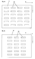
- the first layer 11 consists of a large number of elongated layers 11 in a first direction X channels 111 arranged in rows in the X direction are arranged one behind the other, the distances between the channels in the Rows are slightly smaller than the length of the channels. The distance between the Rows are also slightly smaller than the length of the channels.
- the second layer 12 also consists of a plurality of elongated channels 121, which are also in the are essentially formed in a first direction X and in a plurality of Rows are arranged one behind the other in the X direction, the channels 121 of the second layer 12 according to the invention arranged at positions on layer 12 are the spaces between two channels 111 in the X direction of the Correspond to layer 11.
- the channels 111 of the first layer 11 and the channels 121 the second layer 12 are also designed and positioned such that when the first and second layers are arranged one above the other, the ends of the channels 121 and 111 overlap, which is shown in FIG. 2.
- 3a and 3b show a third layer 13 and a fourth layer 14 of the first Execution of the present invention analogous to that described above Layers 11 and 12 are formed, with the difference that the channels 131 and 141 are formed substantially in a second direction Y, which is different from the first direction X differs. Suitably close the first direction X and the second direction Y an angle of 90 °.
- Fig. 4 shows the one above the other arranged layers 13 and 14 with channels 131 and 141, which are also how the channels 111 and 121 each overlap at their ends and also each between spaces between two channels of the other layer are arranged.
- Channels 131 and 141 of the third and fourth layers are also such in FIGS Layers 13 and 14 arranged that when layers 11, 12, 13 and 14 are arranged one above the other, the ends of the channels 131 and 141 the ends of the Channels 111 and 121 overlap.
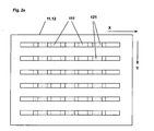
- 5a shows a top view of the one above the other arranged layers 11, 12, 13 and 14, wherein according to the invention the channels in the layers are designed and arranged such that the projection of the Channels on one level result in a grid that has a large number of equally large areas limited.
- FIG. 5a also shows predetermined points E, E and E1, E1, respectively through the formation of suitable bores through the corresponding ones Layers 11, 12, 13 and 14, which are shown symbolically circular in the drawing through which channels 111, 121, 131, 141 can be connected, whereby a Liquid channel is provided between positions E, E and E1, E1, which is shown in the drawing with arrow symbols.
- Layers 11, 12, 13 and 14 with channels 111, 121, 131 and 141 are according to the invention formed and arranged that a variety in the manner described above from positions E, E and E1, E1 using suitable holes in the layer sequence 11, 12, 13 and 14 can be connected to one another via the channels 111, 121, 131 and 141 are.
- the holes are made according to the specifications of the to be connected Positions from above or below through at least two of the four layers.
- the Layer sequence varies according to the specifications of the positions to be connected and / or at least one of the layers 11, 12, 13, 14 be omitted or replaced by another layer 11, 12, 13, 14 which then occurs several times in the layer sequence.
- a distributor plate according to the invention in corresponding positions to be connected also include only two layers 11, 12.
- Channels 111, 121, 131 and 141 in layers 11, 12, 13 and 14 can also be formed such that the channels in the top of the layers are formed to a depth which is less than the layer thickness, the Layers 11, 12, 13 and 14 can be arranged directly one above the other, whereby the top of a layer from the bottom of the overlying layer is covered, and the channels are enclosed between two layers.
- FIG. 5b shows a first distributor plate 1 according to the invention with one above the other arranged layers 11, 12, 13 and 14, the top layer 14 also can be covered with a thin cover film D.
- Suitable are the Layers 11, 12, 13 and 14 and the cover layer D by means of heat, pressure or Adhesive bonded together so that channels 111, 121, 131 and 141 are enclosed in the distribution plate 1 in a liquid-tight and gas-tight manner.
- the cover sheet D a thickness that is sufficient inclusion of the Channels guaranteed and is also sufficiently thin to z.
- B. means Laser ablation or mechanical or thermal means in a simple way To be able to make holes through the cover layer D. Is accordingly also the depth of channels 111, 121, 131 and 141 into layers 11, 12, 13, 14 selected.
- Fig. 5c shows a modification of the distributor plate 1 of Fig. 5b, in which the channels 111, 121, 131 and 141 passing through layers 11, 12, 13 and 14 are formed, an intermediate view D. between adjacent layers is arranged, which covers the channels and also under the lowest layer a base layer G is arranged.
- the thickness of the intermediate layers D are as well as the cover layer D and base layer G are selected such that on holes in the layers D and G can be easily made can and the channels are liquid and gas tight.
- Moreover can also with corresponding specifications of the positions to be connected at least one of the intermediate layers D and preferably the intermediate layer D between the middle layers 12 and 13 are omitted, in which case the middle layers 12 and 13 bonded together at predetermined positions are.
- a distribution plate according to the invention consisting of at least two layers arranged one above the other according to the above with reference to FIGS. 5b and 5c described distribution plate is particularly suitable for providing the Drilling using laser ablation of material between two on top of each other arranged channels, since only a small amount of laser is required for this.
- This also applies to the versions described below with at least two Layers while for laser ablation of material between in one layer side by side channels an increased use of laser is required.
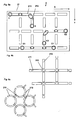
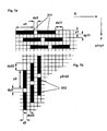
- FIG. 6a shows a second embodiment of the present invention, in which in a Layer 21 has a plurality of elongated channels 211 in a first direction X is formed and also a plurality of second elongated channels 212 in a second direction Y is formed.
- Channels 211 and 212 in layer 21 are suitably arranged so that a large number of equal areas each of two opposite channels 211 and two opposite Channels 212 is included, and the channels at their ends are spaced from one another in a simple manner by means of laser ablation or mechanical or thermal means a connection between a first Channel 211 or a second channel 211 or a first channel 212 and one second channel 212 or a first channel 211 and a second channel 212 can be provided.
- the direction X and the close Direction Y at an angle of 90 °. It is clear that another angle between the two directions X and Y can be advantageous, such as an angle of 60 °, the channels 211 and 211 then correspondingly are formed and arranged such that two opposite channels 211 and 212 include a diamond-shaped surface.
- Fig. 6b shows a section of an advantageous modification of Fig. 6a, the in addition to the elongated channels 211, 212 a plurality of recesses 213, suitably opposite the respective ends of the channels 211, 212 are arranged.
- This arrangement of the channels 211, 212 and Recesses 213 can be made in a simple manner by means of e.g. laser ablation Connection between at least two channels 211, 211 or 212, 212 or 211, 212 are provided by the respective partition between the channel 211, 212 and the recess 213 is removed.
- 6c shows a section of a further advantageous modification of the 6a, whose elongated channels in the first X and second Y Direction 211 and 212 are alternately arcuate.
- a distributor plate consists of the layer 21, over which a thin cover film can be arranged and can also have an additional base layer.
- the top layer and the base layer have a thickness that makes it easy to use a laser and mechanical or thermal means to drill holes in the layers and also reliably enclosing channels to 211, 212 guarantee.
- suitable holes are shown as an example positions E, E and E1, E1 and E2, E2 via channels 211, 212 are suitable connect with each other.
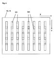
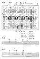
- FIG. 8a shows a plan view of a layer 31 of a third embodiment of the present invention
- FIG. 7a shows a section of the layer 31 from FIG. 8a.
- the layer 31 is rectangular, for example, and in the layer 31 first elongated channels 311 arranged substantially in a first direction X.
- the first elongated channels have a first length x1 and a first width y1 and a plurality of the first channels are in a plurality in the first direction X of rows arranged, the channels 311 in the rows with the same first distance dx1 are arranged, and wherein two adjacent rows in the first direction X against each other by a first amount of displacement dx11 are shifted and two adjacent rows in a second direction Y one have the first row spacing dy11.
- FIG. 8b shows a top view of a second layer 32 of the third embodiment of the present invention and FIG. 7b shows a section of the layer 32 from FIG. 8b.
- second elongated channels 321 are formed with a second length y2 and a second width x2 and the channels are arranged in a plurality of rows in the second direction Y, the channels being arranged one behind the other in the rows with a constant second distance dy2 , and wherein two adjacent rows in the second direction Y are displaced from one another by a second shift amount dy22 and two adjacent rows in the first direction X have a second row spacing dx22.
- the channels 311 of the first layer 31 and the channels 321 of the second layer 32 are arranged according to the invention in layers 31 and 32 such that if the layers 31 and 32 are arranged one above the other, the two ends of one first channel 311 overlap a central region of two channels 321 and at the same time, a central region of the first channel 311 an end of a third Channel 321 overlaps, and the two ends of one channel 321 in the second Layer 32 each overlap middle regions of two channels 311 in layer 31 and at the same time the central region of the channel 321 an end of a third channel 311 overlaps in layer 31.
- the first length is x1 of the first channels 311 and the second length y2 each approximately 5 times as large as the first width y1 or the second width x2.
- Fig. 9c shows a modification of the distributor plate 3 of Fig. 9b, which accordingly the distributor plate 1 shown in FIG. 5c and the distributor plate described above 1 is modified, which is why a description is also omitted here and instead, reference is made to the above passage.
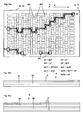
- FIG. 11a shows a top view of the layers 41 and 12 arranged one above the other 42 with holes to corresponding areas E, E and E1, E1 and E2, E2 by means of of channels 421 and 411
- Figs. 11b and 11c show one distributor plate 4 according to the invention, a modification of the above with reference to FIG. 9a, 9b and 9c described distributor plate 3, and why here on another Description is omitted and instead the corresponding above Passage is referred.
- FIG. 12a shows a top view of the layers 41, 42 arranged one above the other with the channels 421 and 422, with previously determined areas E, E and E1, E1 and E2, E2 by means of suitable bores via channels 421 and 422 are connected, however, the holes for providing the connection of the Regions E, E in contrast to the bores of FIG. 11a not only connect channels arranged one above the other, but also in one Connect layers arranged one behind the other, whereby according to the invention Positioning and selection of the holes for connecting predetermined ones Areas E, E is optimized so that a smallest connection channel between the areas E, E is provided.
- Fig. 12b shows an advantageous modification of the fourth embodiment, in which one second layer 42 is arranged between two first layers 41, which are particularly is suitable, for example: to couple two similar components by the distributor plate 4 is arranged between the components.
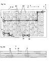
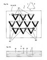
- FIG. 13a and b show a fifth embodiment of the present invention, namely a distributor plate 5 consisting of the layers 51 arranged one above the other, 52 and 53.
- first, second and third layers 51, 52 and 53 are respectively first, second and third elongated channels 511, 521 and 531 of predetermined length and predetermined distance substantially in a first, second and third direction X, Y and Z are formed, according to the invention two of each Directions X, Y, Z enclose an angle of 60 degrees, and one above the other arranged layers 51, 52 and 52 the ends of the channels of a layer 51, 52, 53 above or below the ends of a channel of the other two layers are arranged.
- FIG. 14 shows a distributor plate 5 of an advantageous modification of the fifth Implementation of the present invention, which also consists of a first, second and third layer 51, 52 and 53, in each of which there are first, second and third elongated channels 511, 521 and 531 of predetermined length and predetermined Distance essentially in a first, second and third direction X, Y and Z are formed, and in each case two of the directions X, Y, Z form an angle enclose of 60 °.
- a distributor plate 5 of an advantageous modification of the fifth Implementation of the present invention which also consists of a first, second and third layer 51, 52 and 53, in each of which there are first, second and third elongated channels 511, 521 and 531 of predetermined length and predetermined Distance essentially in a first, second and third direction X, Y and Z are formed, and in each case two of the directions X, Y, Z form an angle enclose of 60 °.
- Distribution plate 5 are channels 511, 521 and 531 in layers 51, 52 and 53 here advantageously designed such that when layers 51, 52 are arranged one above the other, and 53 a first end of a first channel 511, 521, 531 in a first layer 51, 52, 53 with one end of a second channel 511, 521, 531 in a second Layer 51, 52, 53 and with a central region of a third channel 511, 521, 531 overlaps in a third layer 51, 52, 53; and also a second end of the first channel 511, 521, 531 in the first layer 51, 52, 53 with one End of a fourth channel 511, 521, 531 in the third layer 51, 52, 53 and with a central region of a fifth channel 511, 521, 531 in the second layer 51, 52, 53 overlap; and also a central area of the first channel 511, 521, 531 in the first layer 51, 52, 53 with one end of a sixth and seventh channel 511, 521, 531 overlap
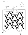
- FIG. 15 shows a section of a distributor plate 5, another advantageous one Modification of the fifth embodiment of the present invention, which also consists of a first, second and third layer 51, 52 and 53, in each of which first, second and third elongated channels 511, 521 and 531 of predetermined length and predetermined distance substantially in first, second and third Direction X, Y and Z are formed, and in each case two directions X, Y, Z enclose an angle of 60 °.
- first, second and third layer 51, 52 and 53 in each of which first, second and third elongated channels 511, 521 and 531 of predetermined length and predetermined distance substantially in first, second and third Direction X, Y and Z are formed, and in each case two directions X, Y, Z enclose an angle of 60 °.
- 13 and 14 described distributor plates 5 are the channels 511, 521 and 531 in the Layers 51, 52 and 53 here advantageously formed so curved that at layers 51, 52 and 53 arranged one above the other, the two ends of a first one Channel 511, 521, 531 in a first layer 51, 52, 53 each with a first middle area of a second channel 511, 521, 531 or third channel 511, 521, 531 overlaps in a second layer 51, 52, 53; and also a first and second middle region of the first channel 511, 521, 531 in the first layer 51, 52, 53 each with a fourth and fifth channel 511, 521, 531 in a third Layer overlaps, with the second and third channels 511, 521, 531 in the second Layer are arranged substantially opposite one another, and the fourth and fifth channel 511, 521, 531 in the third layer essentially in succession are arranged.
- the channels 511, 521, 531 in the layers 51, 52, 53 are according to the invention also arranged and designed such that two opposite channels 511, 511 and 521, 521 and 531, 531 of the first and second and third layers 51, 52, 53 essentially a circular area with a Include diameter Kd, which is essentially a row spacing Dx, Dy, Dz of channels 511, 521, 531 corresponds to the successive in the first or second or third direction X, Y, Z are arranged.
- a distributor plate 5 according to the invention described above according to FIG. 15 can be used in a particularly simple manner from above or below Positions holes are made by laser ablation, so that each a channel of a middle layer 51, 52, 53 with a channel of an upper or lower layer 51, 52, 53 is connected, as compared to a Laser ablation of walls between channels arranged in a layer particularly little energy is required. It is clear that this advantage also for the Corresponding embodiments of the present invention described above apply.
- FIG. 16a shows a plan view of an advantageously designed channel K one Layer D
- Fig. 16b shows a section through the channel K of Fig. 16a along the line A-A, the ends of which are rounded, which is fluidically special is cheap.
- 16c and d each show a channel K1 of a layer D1 and a channel K2 a layer D2, which advantageously overlap at the ends such that the end one channel K1, K2 projects slightly beyond the other channel K1, K2.
- this configuration is particularly advantageous for channels with 16a and b rounded ends and on the other hand particularly advantageous for the embodiments of the present invention described above, at which are both channels of a layer arranged one behind the other as well superimposed channels of different layers by means of suitable Holes are connectable, which ensures that holes for Connection of channels arranged one behind the other in a layer also not an unintentional connection to a channel in another layer cause.
- the present invention also provides a method using the simple and inexpensive way to produce a liquid distribution plate can be.
- This becomes at least one Layer selected and arranged appropriately and at predetermined positions suitable holes are formed in the layer or layer sequence, so that at least one liquid channel is provided.
- distribution plates consisting of one suitable combination of at least two layers arranged one above the other the above first to fifth embodiment can be advantageous, the holes to provide suitable connections of the channels from above and / or are executable below, and after having provided the holes with a thin film can be covered, and in the top and / or bottom of the Distribution plate at predetermined positions E, E1 also by means of laser ablation, etc. openings for coupling are provided.
Abstract
Description
Die vorliegenden Erfindung betrifft eine Verteilerplatte für Flüssigkeiten und Gase und insbesondere eine Verteilerplatte zum Verteilen von sehr kleinen Flüssigkeits-und/oder Gasmengen.The present invention relates to a distributor plate for liquids and gases and in particular a distributor plate for distributing very small liquids and / or Gas quantities.
Mit zunehmender Miniaturisierung von insbesondere auch chemischen und biologischen Analyseverfahren, bei denen vielfach nur in sehr geringen Mengen vorliegende und im wässrigen Milieu gelöste Substanzen untersucht werden, befindet sich die gegenwärtige Entwicklung des Standes der Technik auf dem Wege hin zu einem sogenannten "Lab on a Chip". Bei einem derartigen biochemischen Untersuchungslabor, das auf einem elektronischen Halbleiter angeordnet sein kann, ist es daher wünschenswert, die im wässrigen Milieu vorliegenden zu untersuchenden biochemischen Substanzen an für die vorzunehmenden Untersuchungen geeigneten Positionen anzuordnen, wobei auch entsprechende Mittel zum Transport der Flüssigkeiten bereitgestellt werden müssen. Eine Zu- und Ableitung der Flüssigkeiten in und von dem miniaturisierten Labor erfolgt dabei per Hand oder automatisiert mittels geeignet ausgebildeter Pipetten. Dies ist jedoch einerseits sehr zeitaufwendig und teuer und andererseits werden für ein automatisiertes Auftragen sehr aufwendig konstruierte Automaten benötigt, deren Bereitstellung ebenfalls sehr kostspielig ist. Es wurde daher versucht, in dem miniaturisierten Labor geeignete Kanäle auszubilden, deren Enden über Schläuche mit sehr kleinem Durchmesser mit Behältern der Proben verbunden sind. Die Montage derartiger Schläuche ist jedoch ebenfalls sehr aufwendig und dementsprechend teuer.With increasing miniaturization of chemical and biological analysis methods, in which often only in very small quantities substances present and dissolved in the aqueous environment are examined, the current development of the state of the art is on the way towards a so-called "lab on a chip". With such a biochemical Investigation laboratory, which can be arranged on an electronic semiconductor, it is therefore desirable to add those present in the aqueous medium investigating biochemical substances for the to be carried out To arrange examinations suitable positions, also corresponding Means for transporting the liquids must be provided. A feed and Liquids are drained into and from the miniaturized laboratory by Manual or automated using suitably trained pipettes. However, this is on the one hand very time consuming and expensive and on the other hand for a automated application requires very complex machines, whose Deployment is also very expensive. It was therefore tried in the miniaturized laboratory to form suitable channels, the ends of which are connected by hoses with a very small diameter are connected to containers of the samples. The Assembly of such hoses is also very expensive and accordingly expensive.
Außerdem existieren miniaturisiert ausgebildete pneumatische Mikropumpen mit einem sehr kleinen Ein- und Ausgang für das zu befördernde Medium und außerdem mit mehreren ventilgesteurten Eingängen für den pneumatischen Antrieb der Pumpe, wobei der für den Betrieb der Pumpe erforderliche Druck von einem separaten Druckgenerator bereitgestellt wird. Die Bereitstellung einer Kopplung des externen Druckgenerators an die sehr kleinen Ventileingänge und einer Zu- und Ableitung des zu befördernden Mediums sowie dessen Verteilung auf mehrere Ausgänge ist ebenfalls mit erheblichem Aufwand verbunden und dementsprechend teuer.There are also miniaturized pneumatic micropumps a very small entrance and exit for the medium to be transported and also with several valve-controlled inputs for the pneumatic drive the pump, the pressure required for the operation of the pump of one separate pressure generator is provided. The provision of a coupling of the external pressure generator to the very small valve inputs and an inlet and Derivation of the medium to be transported and its distribution over several Exits are also associated with considerable effort and accordingly expensive.
Die oben beschriebenen Nachteile bestehen nicht nur bei der Zu- und Abfuhr von im wässrigen Medium gelösten Substanzen oder Gasen, sondern beispielsweise auch bei der Zufuhr von Kühlflüssigkeit in wärmeempfindliche elektronische Bauteile, und es ist festzustellen, dass diese Nachteile generell bei der Zu- und Abfuhr und Verteilung von Flüssigkeiten und Gasen in sehr kleine Kanäle oder Räume (Behälter) bestehen.The disadvantages described above exist not only in the supply and removal of im aqueous medium dissolved substances or gases, but also for example in the supply of coolant in heat-sensitive electronic components, and it should be noted that these disadvantages generally apply to the supply and removal Distribution of liquids and gases in very small channels or rooms (Container) exist.
Aufgabe der vorliegenden Erfindung ist daher, eine Vorrichtung bereitzustellen, die
es ermöglicht, auf einfache Weise und kostengünstig Flüssigkeiten und/oder Gase
zu verteilen, so dass eine Flüssigkeit und/oder ein Gas zu vorgegebenen Positionen
an miniaturisierten Bauteilen geführt werden kann und/oder von vorgegebenen
Positionen an miniaturisierten Bauteilen abgeleitet werden kann.
Dabei ist auch Aufgabe der vorliegenden Erfindung, ein Verfahren anzugeben, dass
es auf einfache und kostengünstige Weise ermöglicht, Flüssigkeiten und oder Gase
zu vorbestimmten Positionen eines miniaturisierten Bauteils oder einer
miniaturisierten Vorrichtung zu transportieren und/oder von diesen abzuleiten.
Weitere Aufgabe der vorliegenden Erfindung ist, eine Vorrichtung bereitzustellen,
die es ermöglicht, auf einfache Weise miniaturisiert ausgebildete Bauteile zu
koppeln, so daß eine Flüssigkeit und/oder ein Gas von einem Bauteil in das andere
Bauteil transportiert werden kann.The object of the present invention is therefore to provide a device which makes it possible to distribute liquids and / or gases in a simple and cost-effective manner, so that a liquid and / or a gas can be guided to predetermined positions on miniaturized components and / or by predetermined positions on miniaturized components can be derived.
It is also an object of the present invention to provide a method that enables liquids and or gases to be transported to and / or derived from predetermined positions of a miniaturized component or a miniaturized device in a simple and inexpensive manner. Another object of the present invention is to provide a device which enables miniaturized components to be coupled in a simple manner, so that a liquid and / or a gas can be transported from one component to the other component.
Die Aufgaben werden mit den Merkmalen der unabhängigen Ansprüche gelöst.
Vorteilhafte Ausführungen der vorliegenden Erfindung sind ohne jede Beschränkung
in den Merkmalen der Unteransprüche und/oder der nachfolgenden Beschreibung
erwähnt. Zum besseren Verständnis der vorliegenden Erfindung wird die
Beschreibung von schematischen Zeichnungen begleitet. Hierzu zeigt:
Die vorliegende Erfindung stellt insbesondere eine Verteilerplatte für Flüssigkeiten und/oder Gase bereit, die aus wenigstens einer Schicht besteht, wobei in der Schicht oder den Schichten eine Vielzahl von ersten länglichen Kanälen mit einer ersten geometrischen Ausbildung im wesentlichen in einer ersten Richtung ausgebildet ist, und außerdem eine Vielzahl von zweiten länglichen Kanälen mit einer zweiten geometrischen Ausbildung im wesentlichen in einer zweiten Richtung ausgebildet ist. Derartige Schichten können insbesondere wenn sie sehr kleine Abmessungen haben und dementsprechend miniaturisiert ausgebildete Kanäle haben auf einfache Weise und kostensparend beispielsweise aus Kunststoff mittels Abformung oder Spritzguß in großer Stückzahl vorgefertigt werden und gelagert werden. Im Bedarfsfall kann in einer derartigen Schicht auf einfache Weise mittels geeigneter Bohrungen in Zwischenräume zwischen nebeneinander angeordnete Kanäle mindestens ein erster und zweiter Kanal miteinander verbunden werden, wobei entsprechende Vorgaben durch den bestimmungsgemäßen Einsatz der Verteilerplatte auf ebenso einfache Weise berücksichtigt werden können.The present invention particularly provides a liquid distribution plate and / or gases, which consists of at least one layer, in which Layer or layers of a plurality of first elongated channels with one first geometric formation essentially in a first direction is formed, and also having a plurality of second elongated channels a second geometric configuration essentially in a second direction is trained. Such layers can be particularly small if they are very small Have dimensions and accordingly miniaturized channels have in a simple and cost-saving way, for example made of plastic Impression or injection molding can be prefabricated and stored in large quantities become. If necessary, such a layer can be used in a simple manner suitable holes in spaces between adjacent Channels at least a first and second channel are connected to each other, where appropriate specifications by the intended use of the Distribution plate can be taken into account in an equally simple way.
Die vorliegende Erfindung stellt insbesondere außerdem eine Verteilerplatte für Flüssigkeiten oder Gase mit einer Schichtenfolge bereit, wobei die Schichtenfolge geeigneterweise aus einer ersten Schicht besteht, in der eine Vielzahl von ersten länglichen Kanälen mit einer ersten geometrischen Ausbildung im wesentlich in einer ersten Richtung ausgebildet ist und außerdem wenigstens aus einer zweiten Schicht besteht, in der eine Vielzahl von zweiten länglichen Kanälen mit einer zweiten geometrischen Ausbildung im wesentlichen in einer zweiten Richtung ausgebildet ist. Erfindungsgemäß werden wenigstens zwei Schichten der ersten und zweiten Schicht übereinander angeordnet, wobei mittels geeigneter Bohrungen in Zwischenräume übereinander und/oder nebeneinander angeordnete Kanäle der ersten und/oder zweiten Schicht mindestens ein erster und zweiter Kanal miteinander verbindbar sind. Auf diese Weise wird ebenso einfach erreicht, dass eine Flüssigkeit oder ein Gas von einer ersten Öffnung des ersten Kanals zu einer zweiten Öffnung des zweiten Kanals fließen kann. Auch das Verbinden mindestens eines ersten Eingangs mit mindestens einem Ausgang ist damit problemlos möglich. Die obige erste Schicht und die obige zweite Schicht können mittels Spritzguß oder Abformung auf einfache Weise in großer Stückzahl vorgefertigt werden und im In particular, the present invention also provides a distribution plate for Liquids or gases with a layer sequence ready, the layer sequence suitably consists of a first layer in which a plurality of first elongated channels with a first geometric formation essentially in is formed in a first direction and also at least from a second Layer in which a plurality of second elongated channels with a second geometric formation essentially in a second direction is trained. According to the invention, at least two layers of the first and second layer arranged one above the other, with suitable bores in Spaces one above the other and / or channels of the first and / or second layer at least a first and second channel are interconnectable. In this way it is just as easy to achieve that a liquid or gas from a first opening of the first channel to one second opening of the second channel can flow. At least connecting a first input with at least one output is therefore easily possible. The above first layer and the above second layer can be injection molded or Impression can be easily prefabricated in large quantities and in
Bedarfsfall entsprechend zu einer mindestens zweischichtigen Verteilerplatte zusammengesetzt werden, wobei mittels Bohrungen an geeigneten Positionen, die durch den bestimmungsgemäßen Einsatz der Verteilerplatte vorgegeben sind, einfach, schnell und kostengünstig wenigstens ein Kanal bereitgestellt werden kann, der geeignet ist, eine Flüssigkeit oder ein Gas von wenigstens einer ersten Position zu wenigstens einer zweiten Position zu leiten.If necessary, corresponding to an at least two-layer distributor plate are put together, using holes in suitable positions, the are determined by the intended use of the distributor plate, at least one channel can be provided simply, quickly and inexpensively, which is suitable for a liquid or a gas from at least a first position to lead to at least a second position.
Mittels einer erfindungsgemäßen Verteilerplatte ist es auf einfache Weise möglich, zwei oder mehr miniaturisiert ausgebildete Bauteile zu koppeln, so daß eine Flüssigkeit und/oder ein Gas von einem Bauteil in das andere Bauteil transportiert und gleichzeitig in das andere Bauteil verteilt werden kann.Using a distributor plate according to the invention, it is possible in a simple manner to couple two or more miniaturized components, so that one Liquid and / or a gas is transported from one component to the other component and can be distributed to the other component at the same time.
Die vorliegende Erfindung stellt außerdem insbesondere eine Verteilerplatte für
Flüssigkeiten und/oder Gase bereit, die geeignet ist, standardisiert ausgebildete
Bauelemente eines modularen Systems miteinander zu koppeln, wobei die
Verteilerplatte entsprechend den Standardisierungen und Normungen des
modularen Systems ausgebildet ist. Dabei ist die Geometrie der Kanäle der
Verteilerplatte an die entsprechenden Vorgaben des modularen Systems angepaßt.
Die hierfür benötigten Öffnungen der Verteilerplatte werden ebenfalls entsprechend
den Vorgaben des modularen Systems auf der Oberseite und/oder Unterseite der
Verteilerplatte bereitgestellt. Dabei kann die Verteilerplatte für die Kopplung zweier
Bauteile vorteilhaft zwischen die beiden Bauteile geschaltet sein.
Eine erfindungsgemäße Verteilerplatte ist ebenfalls besonders geeignet, Öffnungen
lediglich eines Bauteils miteinander zu verbinden, oder zwei oder mehr Bauteile
miteinander zu verbinden, die auf der Oberseite und/oder Unterseite der
Verteilerplatte angeordnet sein können.The present invention also provides, in particular, a distributor plate for liquids and / or gases which is suitable for coupling standardized components of a modular system to one another, the distributor plate being designed in accordance with the standardizations and norms of the modular system. The geometry of the channels of the distributor plate is adapted to the corresponding requirements of the modular system. The openings of the distributor plate required for this are also provided on the top and / or bottom of the distributor plate in accordance with the requirements of the modular system. The distributor plate for coupling two components can advantageously be connected between the two components.
A distributor plate according to the invention is also particularly suitable for connecting openings of only one component to one another, or for connecting two or more components to one another, which can be arranged on the top and / or bottom of the distributor plate.
Fig. 1a und 1b zeigen eine erste Schicht 11 und eine zweite Schicht 12 eine ersten
Ausführung der vorliegenden Erfindung. Die beiden Schichten 11 und 12 sind hier
beispielhaft rechteckig ausgebildet und.haben geeigneter Weise ungefähr die
gleiche Größe. Die erste Schicht 11 besteht aus einer Vielzahl von länglichen in
einer ersten Richtung X angeordneten Kanälen 111, die in X-Richtung in Reihen
hintereinander angeordnet sind, wobei die Abstände zwischen den Kanälen in den
Reihen etwas kleiner als die Länge der Kanäle sind. Der Abstand zwischen den
Reihen ist auch etwas kleiner als die Länge der Kanäle. Die zweite Schicht 12
besteht ebenfalls aus einer Vielzahl von länglichen Kanälen 121, die ebenfalls im
wesentlichen in einer ersten Richtung X ausgebildet sind und in einer Vielzahl von
Reihen in X-Richtung hintereinander angeordnet sind, wobei die Kanäle 121 der
zweiten Schicht 12 erfindungsgemäß an Positionen auf der Schicht 12 angeordnet
sind, die den Zwischenräumen zwischen zwei Kanälen 111 in X-Richtung der
Schicht 11 entsprechen. Die Kanäle 111 der ersten Schicht 11 und die Kanäle 121
der zweiten Schicht 12 sind außerdem derart ausgebildet und positioniert, so dass
bei Übereinanderanordnung der ersten und zweiten Schicht die Enden der Kanäle
121 und 111 sich überlappen, was in Fig. 2 dargestellt ist.1a and 1b show a
Fig. 3a und 3b zeigen eine dritte Schicht 13 und eine vierte Schicht 14 der ersten
Ausführung der vorliegenden Erfindung, die analog zu den oben beschriebenen
Schichten 11 und 12 ausgebildet sind, mit dem Unterschied, dass die Kanäle 131
und 141 im wesentlichen in einer zweiten Richtung Y ausgebildet sind, die sich von
der ersten Richtung X unterscheidet. Geeigneterweise schließen die erste Richtung
X und die zweite Richtung Y einen Winkel von 90° ein. Fig. 4 zeigt die übereinander
angeordneten Schichten 13 und 14 mit den Kanälen 131 und 141, die sich ebenso
wie die Kanäle 111 und 121 jeweils an ihren Enden überlappen und außerdem
jeweils über Zwischenräumen zwischen zwei Kanälen der anderen Schicht
angeordnet sind.3a and 3b show a
Die Kanäle 131 und 141 der dritten und vierten Schicht sind außerdem derart in den
Schichten 13 bzw. 14 angeordnet, dass wenn die Schichten 11, 12, 13 und 14
übereinander angeordnet sind, die Enden der Kanäle 131 und 141 die Enden der
Kanäle 111 und 121 überlappen. Fig. 5a zeigt eine Draufsicht auf die übereinander
angeordneten Schichten 11, 12, 13 und 14, wobei erfindungsgemäß die Kanäle in
den Schichten derart ausgebildet und angeordnet sind, dass die Projektion der
Kanäle auf eine Ebene eine Raster ergibt, das eine Vielzahl gleich großer Flächen
begrenzt. Fig. 5a zeigt außerdem jeweils vorbestimmte Punkte E, E und E1, E1, die
durch die Ausbildung von geeigneten Bohrungen durch die entsprechenden
Schichten 11, 12, 13 und 14, die in der Zeichnung symbolisch kreisförmig dargestellt
sind, über die Kanäle 111, 121, 131, 141 verbunden werden können, wodurch ein
Flüssigkeitskanal jeweils zwischen den Positionen E, E und E1, E1 bereitgestellt ist,
der in der Zeichnung jeweils mit Pfeilsymbolen dargestellt ist. Die Schichten 11, 12,
13 und 14 mit den Kanälen 111, 121, 131 und 141 sind erfindungsgemäß derart
ausgebildet und angeordnet, dass auf die oben beschriebene Weise eine Vielzahl
von Positionen E, E und E1, E1 mittels geeigneter Bohrungen in die Schichtenfolge
11, 12, 13 und 14 über die Kanäle 111, 121, 131 und 141 miteinander verbindbar
sind.
Die Bohrungen werden dabei entsprechend den Vorgaben der zu verbindenden
Positionen von oben oder unten durch wenigstens zwei der vier Schichten geführt.
Bei dieser Ausführung der vorliegenden Erfindung kann außerdem die
Schichtenfolge entsprechend den Vorgaben der zu verbindenden Positionen variiert
werden, und/oder es kann auch wenigstens eine der Schichten 11, 12, 13, 14
weggelassen werden oder durch eine andere Schicht 11, 12, 13, 14 ersetzt sein, die
dann mehrfach in der Schichtenfolge vorkommt. Beispielsweise kann eine
erfindungsgemäße Verteilerplatte bei entsprechenden zu verbindenden Positionen
auch lediglich zwei Schichten 11, 12 umfassen.The holes are made according to the specifications of the to be connected
Positions from above or below through at least two of the four layers.
In this embodiment of the present invention, the
Layer sequence varies according to the specifications of the positions to be connected
and / or at least one of the
Die Kanäle 111, 121, 131 und 141 in den Schichten 11, 12, 13 und 14 können
außerdem derart ausgebildet sein, dass die Kanäle in der Oberseite der Schichten
bis zu einer Tiefe ausgebildet sind, die geringer ist als die Schichtdicke, wobei die
Schichten 11, 12, 13 und 14 direkt übereinander angeordnet werden können, wobei
die Oberseite einer Schicht von dem Boden der darüberliegenden Schicht
abgedeckt ist, und die Kanäle zwischen zwei Schichten eingeschlossen sind.
Fig. 5b zeigt eine erste erfindungsgemäße Verteilerplatte 1 mit direkt übereinander
angeordneten Schichten 11, 12, 13 und 14, wobei die oberste Schicht 14 außerdem
mit einer dünnen Deckfolie D abgedeckt sein kann. Geeigneter Weise sind die
Schichten 11, 12, 13 und 14 und die Deckschicht D mittels Wärme, Druck oder
Klebstoff miteinander verbunden, so dass die Kanäle 111, 121, 131 und 141
flüssigkeits- und gasdicht in der Verteilerplatte 1 eingeschlossen sind. Dabei hat
geeigneter Weise die Deckfolie D eine Dicke, die einen hinreichenden Einschluß der
Kanäle gewährleistet und außerdem genügend dünn ist, um z. B. mittels
Laserablation oder mechanischen oder thermischen Mitteln auf einfache Weise
Bohrungen durch die Deckschicht D vornehmen zu können. Dementsprechend ist
auch die Tiefe der Kanäle 111, 121, 131 und 141 in die Schichten 11, 12, 13, 14
gewählt.5b shows a
Fig. 5c zeigt eine Abwandlung der Verteilerplatte 1 von Fig. 5b, bei der die Kanäle
111, 121, 131 und 141 durch die Schichten 11, 12, 13 und 14 hindurchgehend
ausgebildet sind, wobei zwischen benachbarter Schichten eine Zwischensicht D
angeordnet ist, die die Kanäle abdeckt und außerdem unter der untersten Schicht
eine Grundschicht G angeordnet ist. Die Dicke der Zwischenschichten D sind
ebenso wie die Deckschicht D und Grundschicht G derart ausgewählt, dass auf
einfache Weise Bohrungen in die Schichten D und G vorgenommen werden
können und die Kanäle flüssigkeits- und gasdicht abgeschlossen sind. Außerdem
kann bei entsprechenden Vorgaben der zu verbindenden Positionen auch
wenigstens eine der Zwischenschichten D und vorzugsweise die Zwischenschicht D
zwischen den mittleren Schichten 12 und 13 weggelassen werden, wobei dann die
mittleren Schichten 12 und 13 an vorbestimmten Positionen miteinander verbunden
sind.Fig. 5c shows a modification of the
Eine erfindungsgemäße Verteilerplatte, bestehend aus wenigstens zwei übereinander angeordneten Schichten gemäß der oben anhand von Fig. 5b und 5c beschriebenen Verteilerplatte ist besonders geeignet für eine Bereitstellung der Bohrungen mittels Laserablation von Material zwischen zwei übereinander angeordneten Kanälen, da hierfür nur ein geringer Lasereinsatz erforderlich ist. Dies gilt auch für die nachfolgend beschriebenen Ausführungen mit wenigstens zwei Schichten, während für eine Laserablation von Material zwischen in einer Schicht nebeneinander angeordneten Kanälen ein erhöhter Lasereinsatz benötigt wird.A distribution plate according to the invention, consisting of at least two layers arranged one above the other according to the above with reference to FIGS. 5b and 5c described distribution plate is particularly suitable for providing the Drilling using laser ablation of material between two on top of each other arranged channels, since only a small amount of laser is required for this. This also applies to the versions described below with at least two Layers while for laser ablation of material between in one layer side by side channels an increased use of laser is required.
Fig. 6a zeigt eine zweite Ausführung der vorliegenden Erfindung, bei der in einer
Schicht 21 eine Vielzahl von länglichen Kanäle 211 in einer ersten Richtung X
ausgebildet ist und außerdem eine Vielzahl von zweiten länglichen Kanäle 212 in
einer zweiten Richtung Y ausgebildet ist. Die Kanäle 211 und 212 in der Schicht 21
sind geeigneter Weise derart angeordnet, dass eine Vielzahl gleich großer Flächen
jeweils von zwei gegenüberliegenden Kanälen 211 und zwei gegenüberliegenden
Kanälen 212 eingeschlossen wird, und die Kanäle an ihren Enden derart
voneinander beabstandet sind, dass auf einfache Weise mittels Laserablation oder
mechanischen oder thermischen Mitteln eine Verbindung zwischen einem ersten
Kanal 211 oder einem zweiten Kanal 211 oder einem ersten Kanal 212 und einem
zweiten Kanal 212 oder einem ersten Kanal 211 und einem zweiten Kanal 212
bereitgestellt werden kann. Geeigneter Weise schließen die Richtung X und die
Richtung Y einen Winkel von 90° ein. Es ist klar, dass auch ein anderer Winkel
zwischen den beiden Richtungen X und Y von Vorteil sein kann, wie beispielsweise
ein Winkel von 60°, wobei die Kanäle 211 und 211 dann entsprechend derart
ausgebildet und angeordnet sind, dass jeweils zwei gegenüberliegende Kanäle 211
und 212 eine rautenförmige Fläche einschließen.6a shows a second embodiment of the present invention, in which in a
Fig. 6b zeigt einen Ausschnitt einer vorteilhaften Abwandlung von Fig. 6a, die
zusätzlich zu den länglichen Kanälen 211, 212 eine Vielzahl von Ausnehmungen
213 aufweist, die geeigneter Weise gegenüber den jeweiligen Enden der Kanäle
211, 212 angeordnet sind. Durch diese Anordnung der Kanäle 211, 212 und der
Ausnehmungen 213 kann auf einfache Weise mittels z.B: Laserablation eine
Verbindung zwischen wenigstens zwei Kanälen 211, 211 oder 212, 212 oder 211,
212 bereitgestellt werden, indem die jeweilige Zwischenwand zwischen dem Kanal
211, 212 und der Ausnehmung 213 entfernt wird.Fig. 6b shows a section of an advantageous modification of Fig. 6a, the
in addition to the
Fig. 6c zeigt einen Ausschnitt einer weiteren vorteilhaften Abwandlung der
Ausführung von Fig. 6a, deren längliche Kanäle in der ersten X und zweiten Y
Richtung 211 bzw. 212 alternierend bogenförmig ausgebildet sind.6c shows a section of a further advantageous modification of the
6a, whose elongated channels in the first X and
Eine Verteilerplatte gemäß einer zweiten Ausführung der vorliegenden Erfindung
besteht aus der Schicht 21, über der eine dünne Deckfolie angeordnet sein kann
und auch eine zusätzliche Grundschicht haben kann. Dabei sind die Kanäle 211,
212 in der Schicht 21 bis zu einer vorbestimmten Tiefe ausgebildet bzw. durch die
Schicht 21 hindurchgehend ausgebildet. Die Deckschicht und die Grundschicht
haben eine Dicke, die es gestattet, auf einfache Weise mittels Laser und
mechanischen oder thermischen Mitteln Bohrungen in die Schichten vorzunehmen
und außerdem ein zuverlässiges Einschließen der Kanäle zu 211, 212
gewährleisten. In Fig. 6a sind beispielhaft geeignete Bohrungen dargestellt, die
geeignet sind, die Positionen E, E und E1, E1 und E2, E2 über die Kanäle 211, 212
miteinander zu verbinden.A distributor plate according to a second embodiment of the present invention
consists of the
Fig. 8a zeigt eine Draufsicht auf eine Schicht 31 einer dritten Ausführung der
vorliegenden Erfindung, und Fig. 7a zeigt einen Ausschnitt der Schicht 31 von Fig.
8a. Die Schicht 31 ist beispielhaft rechteckig ausgebildet und in der Schicht 31 sind
erste längliche Kanäle 311 im wesentlichen in einer ersten Richtung X angeordnet.
Die ersten länglichen Kanäle haben eine erste Länge x1 und eine erste Breite y1
und eine Vielzahl der ersten Kanäle sind in der ersten Richtung X in einer Vielzahl
von Reihen angeordnet, wobei die Kanäle 311 in den Reihen mit gleichbleibendem
ersten Abstand dx1 angeordnet sind, und wobei zwei benachbarte Reihen in der
ersten Richtung X um einen ersten Verschiebungsbetrag dx11 gegeneinander
verschoben sind und zwei benachbarte Reihen in einer zweiten Richtung Y einen
ersten Reihenabstand dy11 haben.8a shows a plan view of a
Fig. 8b zeigt eine Draufsicht auf eine zweite Schicht 32 der dritten Ausführung der
vorliegenden Erfindung und Fig. 7b zeigt einen Ausschnitt der Schicht 32 von Fig.
8b. In der Schicht 32 sind zweite längliche Kanäle 321 mit einer zweiten Länge y2
und einer zweiten Breite x2 ausgebildet und die Kanäle sind in der zweiten Richtung
Y in einer Vielzahl von Reihen angeordnet, wobei die Kanäle in den Reihen mit
gleichbleibendem zweiten Abstand dy2 hintereinander angeordnet sind, und wobei
zwei benachbarte Reihen in der zweiten Richtung Y um einen zweiten
Verschiebungsbetrag dy22 gegeneinander verschoben sind und zwei benachbarte
Reihen in der ersten Richtung X einen zweiten Reihenabstand dx22 haben. Die
zweite Schicht 32 ist geeigneter Weise gleich groß wie die erste Schicht 31, und die
Kanäle 311 der ersten Schicht 31 und die Kanäle 321 in der zweiten Schicht 32 sind
geeigneter Weise geometrisch gemäß der folgenden Gleichung G1 ausgebildet:
Die Kanäle 311 der ersten Schicht 31 und die Kanäle 321 der zweiten Schicht 32
sind außerdem geeignet Weise wie folgt ausgebildet:
Die Kanäle 311 der ersten Schicht 31 und die Kanäle 321 der zweiten Schicht 32
sind erfindungsgemäß derart in den Schichten 31 und 32 angeordnet, dass wenn
die Schichten 31 und 32 übereinander angeordnet sind, die beiden Enden eines
ersten Kanals 311 einen mittleren Bereich zweier Kanäle 321 überlappen und
gleichzeitig ein mittlerer Bereich des ersten Kanals 311 ein Ende eines dritten
Kanals 321 überlappt, und die beiden Enden eines Kanals 321 in der zweiten
Schicht 32 jeweils mittlere Bereiche zweier Kanäle 311 in der Schicht 31 überlappen
und gleichzeitig der mittlere Bereich des Kanals 321 ein Ende eines dritten Kanals
311 in der Schicht 31 überlappt. Außerdem ist die erste Länge x1 der ersten Kanäle
311 und die zweite Länge y2 jeweils ungefähr 5 x so groß wie die erste Breite y1
bzw. die zweite Breite x2.The
Zwei entsprechend übereinander angeordnete Schichten 31 und 32, die außerdem
mit einer Decksicht D versehen sein können, bilden die Verteilerplatte 3 der dritten
Ausführung der vorliegenden Erfindung, die in der Fig. 9b dargestellt ist, wobei die
Kanäle 311 und 321 bis zu einer Tiefe in die jeweilige Schicht ausgebildet sind, die
geringer als die Schichtdicke ist. In die erfindungsgemäße Verteilerplatte 3 können
auf ebenso einfache Weise wie in die zuvor beschriebene Verteilerplatte 1 und 2 der
ersten und zweiten Ausführung der vorliegenden Erfindung geeignete Bohrungen
vorgenommen werden, um Bereiche E, E und E1, E2 mittels der Kanäle 311, 321 zu
verbinden, was in Fig. 9a dargestellt ist. Dies geschieht analog zu den oben
beschriebenen Ausführungen 1 und 2, weshalb auf eine weitere Ausführung hier
verzichtet wird und statt dessen auf die entsprechenden Passagen der
Beschreibung der Ausführung 1 und 2 verwiesen wird.Two
Fig. 9c zeigt eine Abwandlung der Verteilerplatte 3 von Fig. 9b, die entsprechend
der in Fig. 5c dargestellten Verteilerplatte 1 und oben beschriebenen Verteilerplatte
1 abgewandelt ist, weshalb hier ebenfalls auf eine Beschreibung verzichtet wird und
statt dessen auf die obige Passage verwiesen wird.Fig. 9c shows a modification of the
Fig. 10a und 10b zeigen eine erste Schicht 41 und eine zweite Schicht 42 einer
Verteilerplatte 4 gemäß einer vierten Ausführung der vorliegenden Erfindung, wobei
die Geometrie der Kanäle 411, 421 in der ersten und zweiten Schicht 41, 42
ebenfalls der obigen Gleichung G1 genügt. Die erste Schicht 41 mit den Kanälen
411 und die zweite Schicht 42 mit den Kanälen 421 entsprechen außerdem der
ersten Schicht 31 mit den Kanälen 311 bzw. der zweiten Schicht 32 mit den Kanälen
321 der dritten Ausführung der vorliegenden Erfindung mit den folgenden
Unterschieden:
Fig. 11a zeigt eine Draufsicht auf die übereinander angeordneten Schichten 41 und
42 mit Bohrungen, um entsprechende Bereiche E, E und E1, E1 und E2, E2 mittels
der Kanäle 421 und 411 zu verbinden, und Fig. 11b und 11c zeigen eine
erfindungsgemäße Verteilerplatte 4, eine Abwandlung der oben anhand der Fig. 9a,
9b und 9c beschriebenen Verteilerplatte 3, und weshalb hier auf eine weitere
Beschreibung verzichtet wird und statt dessen auf die entsprechende obige
Passage verwiesen wird.11a shows a top view of the
Fig. 12a zeigt eine Draufsicht auf die übereinander angeordneten Schichten 41, 42
mit den Kanälen 421 bzw. 422, wobei ebenfalls vorher bestimmte Bereiche E, E und
E1, E1 und E2, E2 mittels geeigneter Bohrungen über die Kanäle 421 und 422
verbunden sind, wobei jedoch die Bohrungen zur Bereitstellung der Verbindung der
Bereiche E, E im Unterschied zu den Bohrungen der Fig. 11a nicht nur
übereinander angeordnete Kanäle miteinander verbinden, sondern auch in einer
Schicht hintereinander angeordnete Kanäle verbinden, wobei erfindungsgemäß die
Positionierung und Auswahl der Bohrungen zur Verbindung von vorbestimmten
Bereichen E, E dahingehend optimiert ist, dass ein kleinster Verbindungskanal
zwischen den Bereichen E, E bereitgestellt ist.12a shows a top view of the
Fig. 12b zeigt eine vorteilhafte Abwandlung der vierten Ausführung, bei der eine
zweite Schicht 42 zwischen zwei erste Schichte 41 angeordnet ist, die besonders
geeignet ist, um z.B: zwei gleichartige Bauteile zu koppeln, indem die Verteilerplatte
4 zwischen den Bauteilen angeordnet wird.Fig. 12b shows an advantageous modification of the fourth embodiment, in which one
Fig. 13a und b zeigen eine fünfte Ausführung der vorliegenden Erfindung, nämlich
eine Verteilerplatte 5 bestehend aus den übereinander angeordneten Schichte 51,
52 und 53. In der ersten, zweiten und dritten Schicht 51, 52 und 53 sind jeweils
erste, zweite und dritte längliche Kanäle 511, 521 und 531 mit vorbestimmter Länge
und vorbestimmten Abstand im wesentlichen jeweils in einer ersten, zweiten und
dritten Richtung X, Y und Z ausgebildet, wobei erfindungsgemäß jeweils zwei der
Richtungen X, Y , Z einen Winkel von 60 Grad einschließen, und bei übereinander
angeordneten Schichten 51, 52 und 52 die Enden der Kanäle einer Schicht 51, 52,
53 jeweils über bzw. unter den Enden eines Kanals der beiden anderen Schichten
angeordnet sind. 13a and b show a fifth embodiment of the present invention, namely
a
In der Verteilerplatte 5 können ebenso wie bei den oben beschriebenen
Ausführungen 1 bis 4 auf einfache Weise Bohrungen und Öffnungen E, E1
bereitgestellt werden, weshalb hier auf eine weitere Beschreibung verzichtet wird
und statt dessen auf die jeweiligen obigen Passagen verwiesen wird.In the
Fig. 14 zeigt eine Verteilerplatte 5 einer vorteilhaften Abwandlung der fünften
Ausführung der vorliegenden Erfindung, die ebenfalls aus einer ersten, zweiten und
dritten Schicht 51, 52 und 53 besteht, in denen jeweils erste, zweite und dritte
längliche Kanäle 511, 521 und 531 mit vorbestimmter Länge und vorbestimmtem
Abstand im wesentlichen jeweils in einer ersten, zweiten und dritten Richtung X, Y
und Z ausgebildet sind, und wobei jeweils zwei der Richtungen X, Y, Z einen Winkel
von 60° einschließen. Im Unterschied zu der anhand von Fig. 13 beschriebenen
Verteilerplatte 5 sind die Kanäle 511, 521 und 531 in den Schichten 51, 52 und 53
hier vorteilhaft so ausgebildet, daß bei übereinander angeordneten Schichten 51, 52
und 53 ein erstes Ende eines ersten Kanals 511, 521, 531 in einer ersten Schicht
51, 52, 53 sich mit einem Ende eines zweiten Kanals 511, 521, 531 in einer zweiten
Schicht 51, 52, 53 und mit einem mittleren Bereich eines dritten Kanals 511, 521,
531 in einer dritten Schicht 51, 52, 53 überlappt; und außerdem ein zweites Ende
des ersten Kanals 511, 521, 531 in der ersten Schicht 51, 52, 53 sich mit einem
Ende eines vierten Kanals 511, 521, 531 in der dritten Schicht 51, 52, 53 und mit
einem mittleren Bereich eines fünften Kanals 511, 521, 531 in der zweiten Schicht
51, 52, 53 überlappt; und außerdem ein mittlerer Bereich des ersten Kanals 511,
521, 531 in der ersten Schicht 51, 52, 53 sich mit einem Ende eines sechsten und
siebten Kanals 511, 521, 531 in der zweiten bzw. dritten Schicht überlappt.
Außerdem schließen drei gegenüberliegende Kanäle 511, 521 und 531 der
Verteilerplatte 5 gemäß Fig. 13 und 14 jeweils die Fläche eines gleichseitigen
Dreiecks ein.14 shows a
Fig. 15 zeigt einen Ausschnitt einer Verteilerplatte 5, eine weitere vorteilhafte
Abwandlung der fünften Ausführung der vorliegenden Erfindung, die ebenfalls aus
einer ersten, zweiten und dritten Schicht 51, 52 und 53 besteht, in denen jeweils
erste, zweite und dritte längliche Kanäle 511, 521 und 531 mit vorbestimmter Länge
und vorbestimmtem Abstand im wesentlichen in einer ersten, zweiten und dritten
Richtung X, Y und Z ausgebildet sind, und wobei jeweils zwei Richtungen X, Y, Z
einen Winkel von 60° einschließen. Im Unterschied zu den anhand von Fig. 13 und
14 beschriebenen Verteilerplatten 5 sind die Kanäle 511, 521 und 531 in den
Schichten 51, 52 und 53 hier vorteilhaft derart gebogen ausgebildet, daß bei
übereinander angeordneten Schichten 51, 52 und 53 die beiden Enden eines ersten
Kanals 511, 521, 531 in einer ersten Schicht 51, 52, 53 sich jeweils mit einem ersten
mittleren Bereich eines zweiten Kanals 511, 521, 531 bzw. dritten Kanals 511, 521,
531 in einer zweiten Schicht 51, 52, 53 überlappt; und außerdem ein erster und
zweiter mittlerer Bereich des ersten Kanals 511, 521, 531 in der ersten Schicht 51,
52, 53 jeweils mit einem vierten und fünften Kanal 511, 521, 531 in einer dritten
Schicht überlappt, wobei der zweite und dritte Kanal 511, 521, 531 in der zweiten
Schicht im wesentlichen einander gegenüberliegend angeordnet sind, und der vierte
und fünfte Kanal 511, 521, 531 in der dritten Schicht im wesentlichen hintereinander
angeordnet sind. Die Kanäle 511, 521, 531 in den Schichten 51, 52, 53 sind
erfindungsgemäß außerdem derart angeordnet und ausgebildet, daß jeweils zwei
gegenüberliegende Kanäle 511, 511 und 521, 521 und 531,531 der ersten und
zweiten und dritten Schicht 51, 52, 53 im wesentlichen eine Kreisfläche mit einem
Durchmesser Kd einschließen, der im wesentlichen einem Reihenabstand Dx, Dy,
Dz der Kanäle 511, 521, 531 entspricht, die aufeinanderfolgend in der ersten bzw.
zweiten bzw. dritten Richtung X, Y, Z angeordnet sind.15 shows a section of a
In einer erfindungsgemäßen vorstehend beschriebenen Verteilerplatte 5 gemäß Fig.
15 können auf besonders einfache Weise von oben oder unten an geeigneten
Positionen Bohrungen mittels Laserablation vorgenommen werden, so daß jeweils
ein Kanal einer mittleren Schicht 51, 52, 53 mit einem Kanal einer oberen oder
unteren Schicht 51, 52, 53 verbunden ist, da hierfür im Vergleich zu einer
Laserablation von Wänden zwischen in einer Schicht angeordneten Kanälen
besonders wenig Energie benötigt wird. Es ist klar, daß dieser Vorteil auch für die
oben beschriebenen entsprechenden Ausführungen der vorliegenden Erfindung gilt.In a
Fig. 16a zeigt eine Draufsicht auf einen vorteilhaft ausgebildeten Kanal K einer Schicht D, und Fig. 16b zeigt einen Schnitt durch den Kanal K von Fig. 16a entlang der Linie A-A, dessen Enden gerundet sind, was strömungstechnisch besonders günstig ist.16a shows a plan view of an advantageously designed channel K one Layer D, and Fig. 16b shows a section through the channel K of Fig. 16a along the line A-A, the ends of which are rounded, which is fluidically special is cheap.
Fig. 16c und d zeigen jeweils einen Kanal K1 einer Schicht D1 und einen Kanal K2 einer Schicht D2, die sich an den Enden vorteilhaft derart überlappen, daß das Ende eines Kanals K1, K2 jeweils geringfügig über den andere Kanal K1, K2 hinausragt. Diese Konfiguration ist einerseits besonders vorteilhaft bei Kanälen mit abgerundeten Enden gemäß Fig. 16a und b und andererseits besonders vorteilhaft für die vorstehend beschriebenen Ausführungen der vorliegenden Erfindung, bei denen sowohl hintereinander angeordnete Kanäle einer Schicht als auch übereinander angeordnete Kanäle verschiedener Schichten mittels geeigneter Bohrungen verbindbar sind, wobei hierdurch sichergestellt ist, daß Bohrungen zur Verbindung hintereinander angeordneter Kanäle in einer Schicht nicht außerdem eine unbeabsichtigte Verbindung zu einem Kanal in einer anderen Schicht verursachen. Es ist klar, daß derartige Bohrungen, die auch mehrere Kanäle in einer oder mehr Schichten verbinden, andererseits auch beabsichtigt sein können. Die vorstehend beschriebenen günstigen Ausgestaltungen und Anordnungen der Kanäle gemäß Fig. 16a bis d können bei allen oben beschriebenen entsprechenden mehrschichtigen Ausführungen der vorliegenden Erfindung vorteilhaft eingesetzt werden.16c and d each show a channel K1 of a layer D1 and a channel K2 a layer D2, which advantageously overlap at the ends such that the end one channel K1, K2 projects slightly beyond the other channel K1, K2. On the one hand, this configuration is particularly advantageous for channels with 16a and b rounded ends and on the other hand particularly advantageous for the embodiments of the present invention described above, at which are both channels of a layer arranged one behind the other as well superimposed channels of different layers by means of suitable Holes are connectable, which ensures that holes for Connection of channels arranged one behind the other in a layer also not an unintentional connection to a channel in another layer cause. It is clear that such bores, which also have multiple channels in one or connect more layers, on the other hand can also be intended. The Favorable configurations and arrangements of the Channels according to FIGS. 16a to d can correspond to all of the above-described ones multilayer versions of the present invention are advantageously used become.
Es ist klar, daß die Schichtenfolge der Schichten 51, 52 und 53 ebenso wie die
Bohrungen und Öffnungen zum Ankoppeln, die jeweils von oben und/oder unten
ausgeführt sein können, an die zu verbindenden Bauteile angepaßt sind. Es ist auch
klar, daß zwischen den Schichten 51, 52 und 53 jeweils eine Zwischenschicht
angeordnet sein kann, auf deren Zeichnung hier verzichtet wurde und auf die
entsprechenden Zeichnungen der obigen Ausführung verwiesen wird.It is clear that the layer sequence of
Die vorliegende Erfindung stellt außerdem ein Verfahren bereit mittels dem auf
einfache und kostensparende Weise eine Verteilerplatte für Flüssigkeiten hergestellt
werden kann. Nach dem erfindungsgemäßen Verfahren werden eine Vielzahl von
geeigneten oben beschriebenen Schichten 11, 12, 13, 14; 21; 31, 32; 41; 42 ; 51 ;
52; 53 vorproduziert und auf Lager bereitgehalten; Hieraus wird wenigstens eine
Schicht ausgewählt und geeignet angeordnet und an vorbestimmten Positionen
geeignete Bohrungen in die Schicht bzw. Schichtenfolge ausgebildet, so daß
wenigstens ein Flüssigkeitskanal bereitgestellt ist. Nach geeigneter Weise senkrecht
zur Schicht ausgebildeten Bohrungen werden die Bohrungen versiegelt, was
beispielsweise durch Aufbringen einer dünnen Deckschicht geschehen kann, wobei
klar ist, daß in der Deckschicht und/oder von unten entsprechende Flüssigkeits Ein-und
Ausgänge ausgebildet sind.The present invention also provides a method using the
simple and inexpensive way to produce a liquid distribution plate
can be. A large number of
Die oben beschriebene Erfindung eignet sich insbesondere zur Herstellung von
Verteilerplatten mit Kanälen von sehr kleinen Abmessungen in den Bereichen:
Es ist klar, daß je nach Vorgabe auch Verteilerplatten bestehend aus einer geeigneten Kombination wenigstens zweier übereinander angeordneter Schichten der obigen ersten bis fünften Ausführung vorteilhaft sein kann, wobei die Bohrungen zur Bereitstellung von geeigneten Verbindungen der Kanäle von oben und/oder unten ausführbar sind, und wobei nach der Bereitstellung der Bohrungen diese mit eine dünnen Folie abgedeckt werden, und in die Ober- und/oder Unterseite der Verteilerplatte an vorbestimmten Positionen E, E1 ebenfalls mittels Laserablation, etc. Öffnungen zur Ankopplung bereitgestellt werden.It is clear that, depending on the specification, distribution plates consisting of one suitable combination of at least two layers arranged one above the other the above first to fifth embodiment can be advantageous, the holes to provide suitable connections of the channels from above and / or are executable below, and after having provided the holes with a thin film can be covered, and in the top and / or bottom of the Distribution plate at predetermined positions E, E1 also by means of laser ablation, etc. openings for coupling are provided.
Claims (19)
Applications Claiming Priority (2)
| Application Number | Priority Date | Filing Date | Title |
|---|---|---|---|
| DE10055374A DE10055374B4 (en) | 2000-11-08 | 2000-11-08 | Distributor plate for liquids and gases |
| DE10055374 | 2000-11-08 |
Publications (2)
| Publication Number | Publication Date |
|---|---|
| EP1205670A2 true EP1205670A2 (en) | 2002-05-15 |
| EP1205670A3 EP1205670A3 (en) | 2003-10-29 |
Family
ID=7662589
Family Applications (1)
| Application Number | Title | Priority Date | Filing Date |
|---|---|---|---|
| EP01126695A Withdrawn EP1205670A3 (en) | 2000-11-08 | 2001-11-08 | Manifold for liquids and gases |
Country Status (2)
| Country | Link |
|---|---|
| EP (1) | EP1205670A3 (en) |
| DE (1) | DE10055374B4 (en) |
Cited By (2)
| Publication number | Priority date | Publication date | Assignee | Title |
|---|---|---|---|---|
| WO2011018213A1 (en) | 2009-08-12 | 2011-02-17 | Fraunhofer-Gesellschaft zur Förderung der angewandten Forschung e.V. | 3d microstructuring for generating mixed structures and channel structures in multilayer technology for use in or for the construction of reactors |
| EP2522427A1 (en) * | 2010-11-24 | 2012-11-14 | Fraunhofer-Gesellschaft zur Förderung der angewandten Forschung e.V. | Micro-fluid device and method for manufacturing the same |
Citations (8)
| Publication number | Priority date | Publication date | Assignee | Title |
|---|---|---|---|---|
| CH596453A5 (en) * | 1975-07-18 | 1978-03-15 | Tschudin & Heid Ag | Pneumatic control logic element |
| WO1998033582A1 (en) * | 1997-02-01 | 1998-08-06 | Forschungszentrum Karlsruhe Gmbh | Method and device for producing a dispersed mixture |
| WO1998054568A1 (en) * | 1997-05-27 | 1998-12-03 | Perseptive Biosystems, Inc. | Improved separation columns and methods for manufacturing the improved separation columns |
| WO1999015888A1 (en) * | 1997-09-19 | 1999-04-01 | Aclara Biosciences, Inc. | Capillary electroflow apparatus and method |
| WO1999034909A1 (en) * | 1998-01-06 | 1999-07-15 | Central Research Laboratories Limited | Method of forming interconnections between channels and chambers |
| US5958344A (en) * | 1995-11-09 | 1999-09-28 | Sarnoff Corporation | System for liquid distribution |
| US6074725A (en) * | 1997-12-10 | 2000-06-13 | Caliper Technologies Corp. | Fabrication of microfluidic circuits by printing techniques |
| WO2001089787A2 (en) * | 2000-05-25 | 2001-11-29 | President And Fellows Of Harvard College | Microfluidic systems including three-dimensionally arrayed channel networks |
Family Cites Families (5)
| Publication number | Priority date | Publication date | Assignee | Title |
|---|---|---|---|---|
| GB2097282B (en) * | 1981-04-24 | 1984-06-27 | Raschig Gmbh | Parallel plate contactor |
| DE4237358A1 (en) * | 1992-11-05 | 1994-05-11 | Wiederaufarbeitung Von Kernbre | Mass transfer column with variable distance spaced apart trays - for adjustment of droplet size, hold up and turndown |
| DE69321482T2 (en) * | 1992-12-01 | 1999-04-29 | Sulzer Chemtech Ag | STACKABLE PACKAGE FOR HEAT AND FUEL EXCHANGE |
| DE19708472C2 (en) * | 1997-02-20 | 1999-02-18 | Atotech Deutschland Gmbh | Manufacturing process for chemical microreactors |
| US5993750A (en) * | 1997-04-11 | 1999-11-30 | Eastman Kodak Company | Integrated ceramic micro-chemical plant |
-
2000
- 2000-11-08 DE DE10055374A patent/DE10055374B4/en not_active Expired - Fee Related
-
2001
- 2001-11-08 EP EP01126695A patent/EP1205670A3/en not_active Withdrawn
Patent Citations (8)
| Publication number | Priority date | Publication date | Assignee | Title |
|---|---|---|---|---|
| CH596453A5 (en) * | 1975-07-18 | 1978-03-15 | Tschudin & Heid Ag | Pneumatic control logic element |
| US5958344A (en) * | 1995-11-09 | 1999-09-28 | Sarnoff Corporation | System for liquid distribution |
| WO1998033582A1 (en) * | 1997-02-01 | 1998-08-06 | Forschungszentrum Karlsruhe Gmbh | Method and device for producing a dispersed mixture |
| WO1998054568A1 (en) * | 1997-05-27 | 1998-12-03 | Perseptive Biosystems, Inc. | Improved separation columns and methods for manufacturing the improved separation columns |
| WO1999015888A1 (en) * | 1997-09-19 | 1999-04-01 | Aclara Biosciences, Inc. | Capillary electroflow apparatus and method |
| US6074725A (en) * | 1997-12-10 | 2000-06-13 | Caliper Technologies Corp. | Fabrication of microfluidic circuits by printing techniques |
| WO1999034909A1 (en) * | 1998-01-06 | 1999-07-15 | Central Research Laboratories Limited | Method of forming interconnections between channels and chambers |
| WO2001089787A2 (en) * | 2000-05-25 | 2001-11-29 | President And Fellows Of Harvard College | Microfluidic systems including three-dimensionally arrayed channel networks |
Non-Patent Citations (1)
| Title |
|---|
| DUFFY ET AL: "Rapid Prototyping of Microfluidic Systems in Poly(dimethylsiloxane)" ANALYTICAL CHEMISTRY, AMERICAN CHEMICAL SOCIETY. COLUMBUS, US, Bd. 70, 1998, Seiten 4974-4984, XP002149044 ISSN: 0003-2700 * |
Cited By (2)
| Publication number | Priority date | Publication date | Assignee | Title |
|---|---|---|---|---|
| WO2011018213A1 (en) | 2009-08-12 | 2011-02-17 | Fraunhofer-Gesellschaft zur Förderung der angewandten Forschung e.V. | 3d microstructuring for generating mixed structures and channel structures in multilayer technology for use in or for the construction of reactors |
| EP2522427A1 (en) * | 2010-11-24 | 2012-11-14 | Fraunhofer-Gesellschaft zur Förderung der angewandten Forschung e.V. | Micro-fluid device and method for manufacturing the same |
Also Published As
| Publication number | Publication date |
|---|---|
| DE10055374A1 (en) | 2002-05-29 |
| DE10055374B4 (en) | 2006-03-02 |
| EP1205670A3 (en) | 2003-10-29 |
Similar Documents
| Publication | Publication Date | Title |
|---|---|---|
| DE4416343C2 (en) | Static micro mixer | |
| EP1674152B1 (en) | Static micromixer | |
| EP0879083A1 (en) | Device for mixing small quantities of liquids | |
| DE102011078770B4 (en) | Microfluidic device, microfluidic system and method of transporting fluids | |
| DE10106996C2 (en) | Device for connecting micro components | |
| EP1075326B1 (en) | Device for transporting liquids along predetermined guideways | |
| DE102005035247B4 (en) | Fluid distributor with binary structure | |
| DE10317263B4 (en) | Plate heat exchanger with double-walled heat exchanger plates | |
| DE102016205947B4 (en) | Cleaning nozzle with curved jet for a steam and / or high-pressure cleaner | |
| DE102010041833B4 (en) | Microfluidic chip with multiple cylinder-piston arrangements | |
| EP1205670A2 (en) | Manifold for liquids and gases | |
| EP2522427B1 (en) | Micro-fluid device and method for manufacturing the same | |
| DE102007015171A1 (en) | Membrane device and method of making a membrane device | |
| WO2006034666A1 (en) | Microchannel recuperator produced from stacked films | |
| DE4304440B4 (en) | Valve | |
| DE102012201714A1 (en) | Method for manufacturing micro fluid system used in e.g. medical field, involves providing connecting element with respect to the position on the primary polymer layer | |
| DE102022209418A1 (en) | Microfluidic device and method for its operation | |
| DE102019132096B3 (en) | Device for cooling battery cells | |
| DE102010039676B4 (en) | Cooling system for cooling electronic components | |
| EP1404447B1 (en) | Analysis device | |
| DE3545559A1 (en) | Heat exchanger, in particular for a heating and/or air conditioning system of a motor vehicle | |
| DE102022113631A1 (en) | Analysis system with microfluidic analysis device and microfluidic cartridge | |
| DE202023101236U1 (en) | Two-part housing cover for a heat exchanger, in particular for a motor vehicle | |
| DE102021001455A1 (en) | Column packing element and method | |
| DE3149111A1 (en) | TRANSPORTATION DEVICE IN A DEVELOPMENT DEVICE FOR PHOTOGRAPHIC LAYER |
Legal Events
| Date | Code | Title | Description |
|---|---|---|---|
| PUAI | Public reference made under article 153(3) epc to a published international application that has entered the european phase |
Free format text: ORIGINAL CODE: 0009012 |
|
| AK | Designated contracting states |
Kind code of ref document: A2 Designated state(s): AT BE CH CY DE DK ES FI FR GB GR IE IT LI LU MC NL PT SE TR |
|
| AX | Request for extension of the european patent |
Free format text: AL;LT;LV;MK;RO;SI |
|
| PUAL | Search report despatched |
Free format text: ORIGINAL CODE: 0009013 |
|
| AK | Designated contracting states |
Kind code of ref document: A3 Designated state(s): AT BE CH CY DE DK ES FI FR GB GR IE IT LI LU MC NL PT SE TR |
|
| AX | Request for extension of the european patent |
Extension state: AL LT LV MK RO SI |
|
| AKX | Designation fees paid | ||
| REG | Reference to a national code |
Ref country code: DE Ref legal event code: 8566 |
|
| STAA | Information on the status of an ep patent application or granted ep patent |
Free format text: STATUS: THE APPLICATION IS DEEMED TO BE WITHDRAWN |
|
| 18D | Application deemed to be withdrawn |
Effective date: 20040430 |