EP1207797B1 - Method and apparatus for intracellular electro-manipulation - Google Patents
Method and apparatus for intracellular electro-manipulation Download PDFInfo
- Publication number
- EP1207797B1 EP1207797B1 EP00955350A EP00955350A EP1207797B1 EP 1207797 B1 EP1207797 B1 EP 1207797B1 EP 00955350 A EP00955350 A EP 00955350A EP 00955350 A EP00955350 A EP 00955350A EP 1207797 B1 EP1207797 B1 EP 1207797B1
- Authority
- EP
- European Patent Office
- Prior art keywords
- pulse
- cells
- pulses
- electric field
- nsec
- Prior art date
- Legal status (The legal status is an assumption and is not a legal conclusion. Google has not performed a legal analysis and makes no representation as to the accuracy of the status listed.)
- Expired - Lifetime
Links
Images


Classifications
-
- A—HUMAN NECESSITIES
- A61—MEDICAL OR VETERINARY SCIENCE; HYGIENE
- A61B—DIAGNOSIS; SURGERY; IDENTIFICATION
- A61B18/00—Surgical instruments, devices or methods for transferring non-mechanical forms of energy to or from the body
- A61B18/04—Surgical instruments, devices or methods for transferring non-mechanical forms of energy to or from the body by heating
- A61B18/12—Surgical instruments, devices or methods for transferring non-mechanical forms of energy to or from the body by heating by passing a current through the tissue to be heated, e.g. high-frequency current
- A61B18/1206—Generators therefor
-
- A—HUMAN NECESSITIES
- A61—MEDICAL OR VETERINARY SCIENCE; HYGIENE
- A61P—SPECIFIC THERAPEUTIC ACTIVITY OF CHEMICAL COMPOUNDS OR MEDICINAL PREPARATIONS
- A61P3/00—Drugs for disorders of the metabolism
- A61P3/04—Anorexiants; Antiobesity agents
-
- A—HUMAN NECESSITIES
- A61—MEDICAL OR VETERINARY SCIENCE; HYGIENE
- A61P—SPECIFIC THERAPEUTIC ACTIVITY OF CHEMICAL COMPOUNDS OR MEDICINAL PREPARATIONS
- A61P35/00—Antineoplastic agents
Definitions
- Biological cells consist of cytoplasm surrounded by a membrane.
- the cytoplasm is conducting, the membrane, which is made up of a lipid bilayer, can be considered a dielectric.
- the application of electric fields to biological cells causes buildup of electrical charge at the cell membrane, and consequently a change in voltage across the membrane.
- the transmembrane voltage under equilibrium condition is approximately 70 mV.
- the amplitude of these fields (“ E ") must be such that it generates a potential difference ("V m ”) at least on the same order as the resting potential.
- the external electric field required to generate a voltage of the same amplitude as the resting potential across the membrane is on the order of 100 V/cm. Due to their smaller size, the electric field required to affect the membrane permeability of bacteria is much higher, on the order of kV/cm.
- the effect of electric fields on biological cells is not simply dependent on the magnitude of the applied electric field, but also on its duration.
- the model shown in Fig. 1 does not take the effect of structures inside the cell into account.
- the cell (in suspension) is modeled by a resistance and capacitance.
- the capacitive component of the suspension impedance can be neglected.
- the dielectric relaxation time is on the order of nanoseconds.
- the cell membrane can be modeled as capacitor, the cytoplasm as a resistor.
- the outer membrane contains channels which are affected by the applied voltage and allow flow of ions through the membrane, representing a leakage current.
- the voltage-gated channels can be modeled as variable, voltage-dependent resistors.
- ⁇ 1 the resistivity of the suspending medium, e.g. water
- ⁇ 2 being the resistivity of the cytoplasm
- C the capacitance per unit area
- r cell radius (spherical cell).
- the medium was placed in commercially available cuvettes between two plane aluminium electrodes. With a minimum distance of 1 mm, maximum electric fields of 100 kV/cm could be obtained in the 60 and 300 ns systems. However, surface flashover at the suspension surface has limited the maximum field to about 80 kV/cm.
- an electrode array comprising at least one pair of needles capable of being inserted into tissue in vivo , the tissue containing target cells, and being capable of directing the ultrashort electric pulses to said target cells in vivo.
- WO 98/47562 relates to an electrode array apparatus which facilitates the efficient delivery of electrical waveforms, and particularly delivery to a pre-determined three-dimensional region of tissue within a patient.
- a system is provided wherein the electrode array is located in situ in a patient.
- the pre-determined treatment region can then be subject to the electropermeabilisation effects of the electric fields, promoting the introduction of therapeutic agents into cells within the region.
- the electrical waveform provided by a generator can be an exponentially decaying pulse, a square pulse, a unipolar oscillating pulse train or a bipolar pulse train.
- the electric field strength can desirably be between 0.2 kV/cm to 20 kV/cm, more commonly 0.5 kV/cm to 3 kV/cm.
- the pulse duration can be from 100 nanoseconds to 100 milliseconds and there can be from 1 to 10,000 pulses per second. There is no disclosure of electric pulses having a pulse duration of no more than 1 microsecond and an electric field strength of greater than 10 kV/cm.
- Modifications of cells which lead to rupture of the cell membrane can lead to cell death via necrosis, a nonphysiological type of cell destruction. It would be advantageous to be able to initiate cell death via apoptosis in a selective manner. This would allow the destruction of cells without engendering the non-specific damage to surrounding tissues due to inflammation and scarring that is normally observed with necrosis.
- the ability to selectively modify cells in ways that lead to apoptosis could provide a new method for the selective destruction of undesired cells/tissue (e.g., tumor cells, fat cells or cartilage cells) while minimizing side effects on surrounding tissue.
- the present invention relates to an apparatus for destroying target cells according to claims.
- the ultrashort electric field pulse generally has at least a sufficient amplitude and duration when applied as a sequence of pulses to modify subcellular structures in the target cells in at least a transient fashion.
- the amplitude of individual pulses do not exceed the irreversible breakdown field of the target cells.
- the amplitude and duration of the ultrashort electric field pulse(s) are typically chosen so as to be insufficient to permanently alter permeability of surface membranes of the target cells, e.g., by rupturing the surface membranes.
- tissue electroporation consists of electroporation of individual cells. There are two major differences between the electroporation of individual cells in a suspension and the electroporation of tissue.
- tissue the local extracellular electric field depends in a complicated way on the many neighboring cells.
- the ratio of the extra- to intracellular volume is usually small, just the opposite of most in vitro electroporation conditions. This means that if chemical exchange between the intra- and extracellular volumes is the main cause of cell stress, and therefore cell death, tissue electroporation with microsecond pulses may be intrinsically less damaging in vivo than most in vitro electroporation conditions. Since ultrashort pulses can affect only the interior of the cell, such pulses are expected to have roughly the same effect on tissues as on individual cells.
- ultrashort pulses of the type employed in the present method is the low energy of these pulses.
- the electrical power of the pulses may be many megawatts, the energy of these pulses is often so low (due to their extremely short duration) that any thermal effects on cells can be neglected.
- the present pulse power method is thus a "cold" method which can allow modification of cells via electrical effects without creating any substantial related thermal effects.
- the thermal effects associated with the pulses employed in the present method typically only generate temperature increases in the bulk medium or tissue on the order of 1-2°C.
- the ability to electrically modify cells in a "cold" manner is particularly useful where the intent is to selectively modify subcellular structures within a target cell without substantially effecting the cell membrane.
- the apparatus includes a pulse generator capable of producing an ultrashort electric pulse output and a delivery system capable of directing the electric pulse output to target cells, e.g., capable of selectively directing the electric pulse output to targeted cells in vivo in a manner which avoids causing substantial injury to the surrounding tissue.
- the cell was modeled as a homogeneous, conductive medium surrounded by a dielectric membrane. Taking substructures in cells into account, such as the cell nucleus in eukaryotic cells, requires a more complex model of the equivalent circuit.
- HL-60 Leukemia cells can be used to demonstrate the complexity of structures inside the cell.
- the nucleus is clearly visible as are smaller substructures within it, e.g., nucleoli.
- the substructures can be modeled by treating the membrane surrounding the nucleus as a capacitor and the interior of the nucleus as a resistor, both elements in series and in parallel to the resistance which describes the cytoplasm in the first, simplified, equivalent circuit (see, e.g., Fig. 3 ).
- the nucleoli can also be described by an additional capacitor resistor arrangement in parallel to the nucleus resistance.
- p is the resistivity of the target intracellular structure.
- the value for the capacitance of the outer cell surface membrane has been reported in published work (see, e.g., Schwan, Biophysik, 1, 190 (1963 )) and the capacitance of intracellular structures is assumed to be either the same or half of this value, depending on the structure of the specific intracellular membrane.
- the nucleus is surrounded by two lipid bilayer membranes that make up the nuclear envelope, whereas other intracellular structures (e.g., intracellular granules) may have only one lipid bilayer membrane surrounding them.
- IEM intracellular electromanipulation
- the present method typically employs ultrashort electric field pulses having sufficient amplitude and duration to modify subcellular structures in the target cells, at least when applied as a sequence of ultrashort pulses within a relatively short time period, e.g., a sequence of 3-5 ultrashort pulses within a time interval of 10 seconds or less.
- the amplitude and duration of each ultrashort electric field pulse can be chosen so that it is insufficient to alter permeability of surface membranes of the target cells, e.g., by inducing pores in the cell membranes.
- the target cells are present as part of a tissue.
- Each ultrashort electric field pulses typically has a pulse duration of no more than about 1 microsecond and an amplitude of at least about 20 kV/cm.
- the ultrashort electric field pulses typically have a pulse duration of no more than about 1 microsecond and provide a total energy density of at least about 75 mJ/cc. Preferably, the ultrashort electric field pulses provide total energy density of no more than about 10 J/cc.
- the total energy density provided by each ultrashort electric field pulse is about 75 mJ/cc to about 2,000 mJ/cc and, preferably, about 100 mJ/cc to about 1,000 mJ/cc, In instances where extremely short pulses are applied, e.g., pulses having a duration of about 10 nanoseconds or less, the total energy density provided by the electric field pulse may only be on the order of about 10 to 20 ml/cc. In addition to having short durations, the electric field pulses used in the present methods commonly have rise times of 50 nsec or less.
- the amplitude of an electric field (the applied voltage divided by distance between electrodes) pulse is generally at least about 20 kV/cm, but should not exceed the breakdown field of the tissue which includes the target cells.
- the breakdown field increases with decreasing pulse duration, and can be experimentally determined. Under the conditions commonly employed in the present method, however, the breakdown field does generally not exceed 500 kV/cm.
- Electric field pulses employed in the present methods which have durations of 10 to 500 nsec typically have amplitudes of about 20 kV/cm to about 300 kV/cm.
- the electrical field pulses generally have a rapid rise time and short duration.
- the pulses should preferably be less than one microsecond, but more than 100 picoseconds in duration.
- a common pulse duration is about 1 nanosecond to about 500 nanoseconds, with pulses typically having a duration, of about 10 to a 300 nanoseconds.
- the optimum pulse duration will vary depending on the cell type, tissue type and desired treatment, among other factors.
- the pulse should be preferentially rectangular or trapezoidal, but other pulse shapes may also used. For example, in order to open both the outer and inner cell membranes, an intense short pulse might be combined with a less intense longer pulse. Other examples of suitable pulse shapes include exponential decaying pulses, unipolar pulses and bipolar pulses.
- the rise time of the ultrashort electric field pulse is typically no more than about 20% and, preferably, no more than about 10% of the pulse duration. For example, if the pulse duration is about 100 nanoseconds, the rise time of the pulse is preferably about 10 nanoseconds or shorter. For pulses with pulse durations of about 400 nanoseconds or longer, the pulse rise times of about 30-40 nanoseconds are common. With pulses having extremely short durations, e.g., one nanosecond or less, the rise time is often a greater percentage of the pulse duration. For example, pulses with a duration of less than one nanosecond, can commonly have a rise time which is up to about 50 % of the pulse duration.
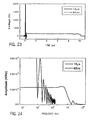
- Figure 24 shows the Fourier spectrum of a short pulse (60 nsec) which extends to the 10 MHz range and for a long pulse (10 microsec) which extends up to the 100 KHz range.
- increasing frequency i.e., decreasing pulse rise time
- the outer surface membrane of the target With increasing frequency (i.e., decreasing pulse rise time), the outer surface membrane of the target will be effectively shorted out, and the applied voltage will appear across the inner (nucleus) membrane.
- Fig. 4 where the voltage across the surface (outer) membrane and that across the nucleus membrane is plotted versus frequency.
- Electric field pulses with duration of less than about 1 microsecond and rise times of 40 nanoseconds or less have Fourier transforms which include frequencies above 1 MHz with substantial amplitudes.
- the Fourier spectrum of the pulses which are employed in the present methods can include frequencies with substantial amplitudes up to about 1 GHz.
- the pulses employed in the present methods have Fourier spectra which include frequencies above 1 MHz with amplitudes greater than 50% of the maximum voltage in the spectrum (referred to hereinafter as greater than "V MAX /2").
- the Fourier spectra of the pulses includes frequencies between 5 to 50 MHz with amplitude greater than V MAX /2.
- a 60 nanosecond rectangular pulse such as depicted in Fig. 21 has a Fourier spectrum which includes frequencies with amplitude greater than V MAX /2 up to about 10 MHz.
- the Fourier spectrum of a 10 microsecond rectangular pulse only has frequencies of this amplitude up to about 200-500 kHz (see comparison in Figs. 23 and 24 ).
- ultrashort electric field pulses within a relatively short time interval.
- a sequence of 3 to 5 ultrashort electric field pulses e.g., trapezoidal pulses with durations of 10-300 nsec and amplitudes of about 25 to 300 kV/cm
- the application of a multipulse sequence with a roughly one second interval (delay) between pulses can rupture granules within eosinophils without significant damage to the outer cell membrane.
- the time interval between subsequent pulses may vary over a wide range, e.g., between 1.0 millisecond and 100 seconds.
- multiple pulse sequences with time interval between pulses of about 0.1 - 3 seconds are quite suitable for initiating apoptosis.
- the multipulse sequences utilized in the present methods typically include up to about 20 pulses, which are generally spaced at regular time intervals.
- Suitable results can often be obtained for certain types of cells (e.g., eosinophils, neutrophils and T-lymphocytes) by applying 3-5 ultrashort electric field pulses within a relatively short time period, e.g., within a time period no longer than about 5 to 10 seconds.
- the amplitude and duration of the ultrashort electric field pulse are typically chosen so that the sequence of pulses does not permanently alter permeability of surface membranes of the target cells, e.g., by rupturing the surface membranes.
- the present method may be used to modify a variety of cells,
- the target cells may be any of a variety of common cells, such as fat cells, bone cells, vascular cells, muscle cells, cartilage cells and the like.
- the technique may be used to selectively modify certain types of cells in the presence of other cells.
- the parameters of the present method may be adjusted to selectively induce apoptosis in tumor cells in vivo (e.g., carcinoma cells, sarcoma cells, or papilloma cells) without substantially affecting normal cells in surrounding tissue.
- the technique may be utilized to selectively destroy eosinophils in a mixture including eosinophils and neutrophils (see, e.g., Table II in Example 4 herein).
- the experiments described herein indicate that the present techniques may be used to selectively modify faster growing cells in the presence of slower growing cells (e,g., cells in stationary phase).
- the selectivity may be simply based on spatially limiting the application of the ultrashort electric field pulse(s).
- cells within a predetermined area of tissue may be selectively modified in vivo (e.g., through initiation of apoptosis) without altering cells in the immediately surrounding tissue.
- Devices which incorporate such electrode configuration are currently employed with conventional electroporation pulses (pulses with ⁇ sec duration) to enhance the delivery of therapeutic drugs to cells within a predetermined area.
- the apparatus of the invention may be used in a method that can be used to initiate apoptosis in target cells by applying at least one ultrashort electric field pulse with a pulse duration of no more than about 1 microsecond to the target cells.
- electric field pulse commonly provides a total energy density of at least about 75 mJ/cc, although pulses with lower energy may be employed, in particular where the pulse has an extremely short duration and a relatively high amplitude or where sequences of multiple pulses are applied to the target cells within a relatively short time interval, e.g., with a spacing of 1-2 seconds between succeeding pulses.
- the present method can be employed to selectively destroying target cells in a mixture including the target cells and a second type of cells.
- the method can be used to selectively destroy eosinophils in a mixture including eosinophils and neutrophils.
- the present method typically employs an apparatus for intracellular electro-manipulation which includes a pulse generator and a delivery system adapted to direct the electric pulse output to target cells.
- the pulse generator includes a pulse forming network and a high voltage switch.
- the pulse forming network may be a high voltage cable, a strip-line, or a pulse forming network constructed of individual capacitors and inductors in a transmission line arrangement.
- the high voltage switch can suitably be a gaseous, liquid or solid state switch.
- the energy in the pulse forming network may be stored capacitively, which requires a closing switch to release a pulse, or inductively, which requires an opening switch to release a pulse.
- an electrical pulse is launched into the load, i.e., the target cells in tissue form.
- the switch can be triggered by a variety of common methods, e.g., optically or electrically. The latter can be accomplished by employing a third electrode or by overvolting the switch.
- An example of a suitable cable pulsed power system, designed to generate ultrashort pulses of the type employed in the present method is shown in Figure 20 .
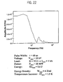
- Figure 21 shows a typical shape of a pulse employed in the present methods and the corresponding Fourier spectrum of the pulse is shown in Figure 22 .
- the electrical field pulses can be varied in length ("duration") by changing the pulse forming network, such as by reducing or increasing the length of the cable or stripline, or by using a switch which can be closed and opened.
- One specific example of an apparatus suitable for modifying cells by intracellular electro-manipulation is described in Example 10 herein.
- the "load,” which includes the target cells in tissue is located between two or more electrodes. These electrodes may be solid material, wires or combinations thereof. One (set of) electrode(s) is connected to the high voltage connection of the pulse generator, and a second (set of) electrode(s) is connected to the ground connection of the pulse generator in a suitable manner, e.g., via a second stripline or high voltage cable.
- the electrode material is a conductor, most commonly metal.
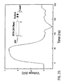
- a typical ultrashort pulse electric field generator (“USPEF generator”) includes a distributed pulse forming network, a switch to allow rapid transfer of electrical energy into the load, and the load itself (see, e.g., Figure 25 , inset). If such a pulse-forming network is charged up to 18 kV, and then released, this charge can produce an almost rectangular ultra-short duration pulse (see Figure 25 ), which when applied to a 10 ⁇ load, produced a maximum voltage of 9 megavolts. The corresponding electric field intensity between two electrodes separated by 1.4 mm is 90 kV/cm. The maximum electrical power, V 2 /R, which can be achieved with these conditions is 8.1 MW, while the energy (power x pulse duration) transferred into the load is only 0.49 Joule. For a 100 ⁇ L volume of cell suspension, the energy density is consequently 4.5 J/cc. This energy transfer results in a calculated maximum temperature increase of only about 1°K for a single pulse.
- the apparatus includes a pulse generator capable of producing ultrashort electric pulses and a delivery system capable of selectively directing the electric pulse output to targeted cells in vivo, e.g., capable of selectively directing the electric pulse output to tumor cells in vivo in a manner which avoids causing substantial injury to the surrounding tissue.
- the pulse generator in an apparatus of this type is typically capable of generating electric pulses having a duration of 1 to 500 nanoseconds and amplitudes of at least 10 kV/cm.
- the delivery system includes one or more pairs of electrodes capable of being inserted into tissue in vivo in the form of an array of needle electrodes. In another configuration, delivery system includes at least one electrode which is an component of a catheter. Basic configurations for such delivery systems are described in WO-A-97/49 450 . For use in the present methods, such delivery systems need not include an infusion port for intravascular administration of a pharmaceutical composition.
- calcein-AM a green fluorescent probe that stains the cytoplasm of live, intact cells, and then exposed to the various IEM pulses.
- the cells were stained with ethidium bromide homodimer (EtBr), a membrane non-permeable red fluorescent probe that stains the nucleus of cells that exhibit plasma membrane damage.
- EtBr ethidium bromide homodimer
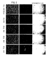
- the cells were centrifuged onto glass slides (cytospin). The cells were observed under conditions for calcein (left panel) or EtBr (middle panel) fluorescence (see Figs. 5-7 ). Images were captured, and the fields marked. The cells were then stained with Wright stain (right panel), the same fields were observed, and images were captured under conditions for light microscopy Images were observed at 10X magnification.
- IEM parameters included sham or control (fresh), A4 (60 nsec, 60 kV/cm), B6 (300 nsec, 40 kV/cm), and B8 (300 nsec, 60 kV/cm). All exposures were at immediately after IEM exposure (T0) and images were at 160X magnification ( Fig. 7 ) or 280X magnification ( Figures 8 and 9 ).
- B8 pulse parameters at T0 after IEM cytoplasmic staining is nearly gone and nuclear staining exhibits significant "pores" or "holes” (right panel).
- the B8 control left panel, Wright stain shows neutrophils not exposed to IEM (normal), but prepared at the same time as B8 IEM exposed neutrophils.
- B5 (right panel, Wright stain) shows IEM conditions (300 nsec, 30 kV/cm) between A4 and B6. Note how "pores" or “holes” begin to become evident in the cytoplasm.
- the B5 control (left panel, Wright stain) shows neutrophils not exposed to IEM (normal), but prepared at the same time as B5 IEM exposed neutrophils.
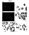
- Figure 8 Neutrophils from A4 and B6 pulse parameters are shown at higher magnification (280X) to more clearly show the cytoplasmic characteristics. The "pores" or “holes” are present in B6, but not A4.
- Figure 9 .
- Neutrophils are shown after myeloperoxidase staining, which stains neutrophil vesicles that contain proteases used for killing bacteria.
- Myeloperoxidase staining at T0 in fresh and A4 IEM parameter appear relatively granular, indicating the presence of numerous small protease-containing vesicles.
- B6 IEM parameters the staining is more diffuse, indicating the presence of vesicle rupture.
- B8 IEM parameters the staining is nearing gone, indicating that nearly all of the vesicles have bee ruptured with the higher energy / power conditions.
- IEM parameters include sham or control (fresh), A4 (60 nsec, 60 kV/cm), B6 (300 nsec, 40 kV/cm), and B8 (300 nsec, 60 kV/cm).
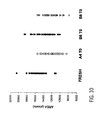
- Cells were stained with Wright stain immediately after being subjected to the IEM pulse, nuclei were set to gray scale and pixel area was determined. Nucleus sizes from 30 to 42 cells were determined and each one plotted according to pixel area.
- IEM parameters required to induce cell death in different cell types were examined. Eosinophils were observed to be more sensitive to IEM than neutrophils. Method: IEM parameters included sham or control (fresh), A4 (60 nsec, 6kV), B6 (300 nsec, 4kV), and B8 (300 nsec, 6kV) as well as additional IEM parameters as indicated.
- Human neutrophil preparations include some contaminating eosinophils, which are more abundant during hay fever/allergy seasons (at the time of these studies). The number of eosinophils was determined as a percentage of the number of neutrophils by morphology and cell counting under light microscopy.
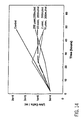
- IEM alters neutrophil function without disrupting the plasma membrane.
- the effects on chemotaxis are different than the effects on unstimulated movement, suggesting a selective effect on neutrophil function.
- Method IEM parameters included sham or control (S), A4 (60 nsec, 60 kV/cm), B6 (300 nsec, 40 kV/cm), and B8 (300 nsec, 60 kV/cm).
- S sham or control
- A4 60 nsec, 60 kV/cm
- B6 300 nsec, 40 kV/cm
- B8 300 nsec, 60 kV/cm
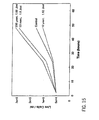
- HL-60 cells were maintained at a density of 100-300,000 cells / ml, conditions for maximal cell doubling time (10-14 h, log phase growth). Cells were exposed to various IEM parameters by maintaining a constant energy exposure (200-250 mJ/ml) at different pulse durations as indicated. The cells were then diluted to 50,000 cells/ml and the viable cell number (cells that excluded trypan blue; i.e.
- live cells was determined after 0, 24, and 48 hours using a hemocytometer under light microscopy. Results: The number of viable cells was not different from control immediately after treatment with IEM (see Fig. 14 ). Twenty-four hours after IEM, treated cells grew at rates similar to control, except under the condition of the longest pulse time (200 ⁇ sec). After 48 hours, the proliferation rate of cells exposed to a pulse of 0.06-10 ⁇ sec began to decrease, indicating more death events than proliferation events. Cells exposed to a pulse of 200 ⁇ sec increased their proliferation rate to near the control rate.
- HL-60 cells were maintained at a density of 1-3,000,000 cells/ml for 3-5 days, conditions for minimal cell doubling time (near stationary phase growth). Cells were exposed to various IEM parameters by maintaining a constant energy exposure (1.7-1.9 J/ml) at different pulse durations as indicated. The cells were then diluted to 50,000 cells/ml and the viable cell number (cells that excluded trypan blue; i.e. live cells) was determined after 0, 24, and 48 hours using a hemocytometer under light microscopy.
- Results The number of viable cells was not significant different from control immediately after treatment with IEM (see Fig. 15 ). After 24 and 48 hours, the proliferation rates were greater than control for cells exposed to a pulse of 0.05 or 200 ⁇ sec. The proliferation rate was less than control for cells exposed to a pulse of 10 ⁇ sec. A pulse duration minimum is observed to inhibit the proliferation of slowly growing cells.
- IEM parameters include sham or control (fresh), A4 (60 nsec, 60 kV/cm, 216 mJ/cc), B6 (300 nsec, 40 kV/cm, 480 mJ/cc), and B8 (300 nsec, 60 kV/cm, 1.08 J/cc).
- Annexin-V-FITC Ethidium bromide homodimer
- Annexin-V-FITC binding was used as a quantitative apoptosis marker.
- Annexin-V exhibits calcium-dependent binding to phosphatidylserine. While phosphatidylserine is typically restricted to the inner leaflet of the cell membrane in normal cells and is therefore inaccessible to Annexin-V in solution, apoptotic cells express phosphatidylserine in their outer membrane leaflet, resulting in ready binding of Annexin-V to their surfaces.
- EtBr binds to DNA, but is impermeable to the cell membrane.
- EtBr fluorescence occurs only in cells that have ruptured membranes. Therefore, apoptotic cells exhibit only Annexin fluorescence while necrotic cells exhibit fluorescence for EtBr plus or minus Annexin fluorescence.
- Cells are exposed to IEM and at the indicated times after IEM, cells are evaluated by fluorescence microscopy, counted, and expressed as percent cells showing apoptosis and necrosis. Results: Control cells (human neutrophils) do not exhibit significant markers for apoptosis or necrosis during the time course of the experiment (see Figs. 16 and 17 ). This indicates that these pulses do not kill the cell by membrane rupture.
- HL-60 cells exposed to IEM conditions A4, B6, and B8 show a time-dependent and an energy- or power-dependent increase in apoptosis.
- A4, B6, and B8, cells begin to show the apoptosis marker after 5, 3, and 1 hours, respectively (see Fig. 16 ).
- necrosis occurs, secondary to apoptosis (see Fig. 17 ). This is indicated by the appearance of necrosis only after apoptosis. Secondary necrosis is an in vitro -specific effect.
- the apoptotic cells are remove by phagocytosis before necrosis and inflammation occur.
- Figures 18 and 19 show similar results for human neutrophils.
- Free calcein is a highly fluorescent modified fluorescein with 6 negative and 2 positive charges that is membrane impermeant. In its methyl ester form, calcein-AM, it is non-fluorescent and membrane permeable. When used as a fluorescent stain for cells, calcein-AM passes through the surface membrane and is cleaved to free calcein + the methyl ester residue by intracellular esterase activities. This modification traps the free calcein in the cytoplasm of the cell, and retention of the free calcein is a common criterion for intactness of the surface membrane.
- the intracellular free calcein In addition to remaining trapped within the cell, the intracellular free calcein also remains excluded from other intracellular membrane-bound compartments because of its membrane impermeant nature (an effect illustrated in calcein-AM labeled eosinophils which show bright cytoplasmic free calcein fluorescence and "negative staining" of their large intracellular granules).
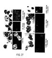
- Calcein-AM stained eosinophils trap free calcein in their cytoplasm after staining (left), and the intracellular free calcein is excluded from the eosinophil's large granules as shown on the left. Without Triton treatment, free calcein is incapable of staining eosinophil cytoplasm (center): only eosinophil autofluorescence visible. With incubation in 0.001% Triton, free calcein continues to be excluded from eosinophils, but stains the fine granules of a PMN showing obvious detergent effects (right) (see Fig. 27 ).
- Triton treatment With 0.005% Triton treatment (left), the morphology of some eosinophils suggests partial detergent solubilization which is accompanied by bright free calcein staining of eosinophil granules, and detergent solubilized PMN show very fine, fluorescent "calcein sand" staining patterns. With 0.01 % Triton + 1 ⁇ M free calcein treatment (center), all eosinophils show nuclear changes suggestive of detergent effect, and many contain 1-2 bright granules on a background of red autofluorescence.
- a typical pulse generator for producing USPEF effects is illustrated in Figure 25 , and consists of a pulse forming network (typically a coaxial cable or a strip line), a switch and the load.
- a pulse forming network typically a coaxial cable or a strip line
- the voltage pulse across the load has an amplitude of half the voltage applied to the pulse-forming network (for the experiments described, the pulse-forming network comprised 5 high voltage 50 ⁇ cables in parallel, which achieved the required 10 ⁇ impedance for matched operation).
- the pulse duration is twice the length of the cable or strip line, divided by the speed of the electromagnetic wave in the dielectric of the pulse-forming network.
- the switch is a simple spark gap in atmospheric air.
- the breakdown voltage is set by varying the gap distance.
- the load consists of the 100 ⁇ L of cell suspension to be exposed to the USPEF, and when Hanks Balanced Salt Solution without Ca ++ and Mg ++ (HBSSw/o) is used to suspend the cells, has an electrical resistivity of 100 ⁇ cm.
- PMN Polymorphonuclear leukocytes
- “Sparkler” cells (cells with cytoplasmic calcein staining plus centrally-located, large, bright fluorescent granules) were seen with both electric field intensities when ⁇ 3 USPEF applications were used (see Table 1). When examined by Wright-Giemsa stain, the “sparkler” cells were always eosinophils, and often appeared “shrunken” relative to the appearance of eosinophils in the control condition.
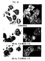
- Figure 26 shows "sparkler" cells in an eosinophil preparation exposed to USPEF treatments (60 nsec, 53 kV/cm x3 (middle) and x5 (below)).
- Control eosinophils labeled with calcein-AM (top) show bright cytoplasmic free calcein staining with exclusion of fluorescence from intracellular granules.
- Application of multiple USPEF treatments to this cell preparation results in appearance of "sparkler" cells with bright cytoplasmic free calcein staining (indicating that the surface membrane is intact) and bright fluorescence of some intracellular granules, indicating that intracellular free calcein has gained access to and labeled the cationic intragranular components.
- the middle panels also illustrate the "shrunken" eosinophil morphology frequently noted in the 60 nsec, 53 kV/m x3 and x5 conditions.
- a normal sized eosinophil with bright cytoplasmic free calcein staining/unstained granules is at right, and 3 "shrunken" eosinophils, all "sparkler” cells, are on the left.
- Eosinophil granules contain a variety of cationic proteins which could potentially bind the highly anionic free calcein if the granule membrane were breached, as shown in the Triton solubilization experiment. Therefore, we conclude that development of "sparkler" morphology in calcein-AM loaded eosinophils following repeated USPEF applications is the result of selective poration/disruption of the eosinophil granule membrane during USPEF applications, which allowed cytoplasmic free calcein to enter the granule and bind to the cationic granule components. We interpret this as strong evidence that selective poration/disruption of intracellular membranes without loss of surface membrane integrity can be achieved with USPEF applications.
- mice Seven to 8 week old immunocompetent C57B1/6 mice were inoculated subcutaneously with 1.5x10 6 B10.2 mouse fibrosarcoma cells in 0.1 ml PBS using a 1 cc syringe fitted with a 27-gauge needle. The injection site was either in the flank region or on the back of the animal. Two to three weeks later the tumors were excised and sliced into two pieces along the equatorial axis. One piece served as a matched control and the other piece was exposed to three pulses each at 300 nsec and 60 kV/cm (1.08 J/cc).
- Tumor slices (0.1 cm thickness) were placed in an electroporation cuvette between two electrodes spaced 0.1 cm apart and Hank's balanced salt solution was added to fill the cuvette.
- the tissues were exposed to pulses as indicated, removed, and prepared for analysis.
- the tissues were incubated for 5 hours at 37°C in RPMI media with 10% fetal bovine serum.
- the tissues were then fixed in 10% buffered formalin for 18 hours.
- the air was removed from the tissues using a vacuum and the degassed tissues were embedded in paraffin.
- Four micron slices were prepared and placed on glass slides pretreated with 2 % APES in acetone.
- the paraffin was removed by successive washes in xylene, absolute ethanol, 95 % ethanol, 70 % ethanol, and PBS.
- the tissue slices were incubated with proteinase K (40ug/ml) for 15 minutes at 40°C.
- the tissue slides were prepared for examination of DNA fragmentation as a marker for apoptosis using a rhodamine-labeled sheep anti-digoxigenin antibody (Apop-tag TM from Intergen) and fluorescence microscopy according to the manufacturers protocol.
- the slides were counterstained with DAPI. Normal nuclei were stained blue by DAPI and apoptotic nuclear were stained red with rhodamine. Two to three hundred cells were counted and scored as blue (normal) or red (apoptotic).
- the apoptotic index is defined as the number of apoptotic nuclei divided by the total number of nuclei. The results are shown in Table IV below.
- Table IV illustrates the apoptotic index (percentage of apoptotic cells) in a representative tumor that was exposed to three consecutive 300 nsec pulses at 6 kV in comparison to an unpulsed control. About 6 % of the nuclei from the control tumor were apoptotic when sampled from four different sections of the same tumor. In contrast, 35% of the nuclei were apoptotic from the tumor exposed to the sequence of ultra-short, high intensity pulses. This represents a 6-fold increase in apoptotic nuclei after exposure to these pulses.
- mice For the mouse fibrosarcoma tumors, the immunocompetent C57B1/6 mouse model will be used. Seven to 8 week old mice will be inoculated subcutaneously or intradermally with 5x10 6 B 10.2 mouse fibrosarcoma cells in 0.1 ml phosphate buffered saline ("PBS ”) using a lcc syringe fitted with a 27-gauge needle. The injection site will be on the back of the animal so as not to interfere with its movement or feeding. Tumor masses are expected to form over a 6-week period into a mass about 5-10 mm in diameter. The mass of the resulting tumor will not be allowed to exceed 10% of body weight before being subjected to the ultrashort electric pulse treatment.
- PBS phosphate buffered saline
- mice with induced subcutaneous tumors will be divided into six different groups and five of the groups will have their tumors exposed to ultrashort electric pulse treatment in vivo.
- the six group will serve as an untreated control group to monitor the course of tumor development.
- the pulse parameters for the five different treatments will be used based on results from the ex vivo experiments.
- the ultrashort electric pulse conditions for the five different groups are shown in Table V below.
- pulses will be delivered through an electrode array consisting of a pair of stainless steel needles the size of acupuncture needles spaced 5mm apart. The pair of needles will be inserted into the tumor or the surrounding margin of healthy tissue at least the depth of the tumor.
- the current will pass synchronously through opposite pairs of needle yielding a homogenous field within and just outside the cross section defined by the needles (see Figure 28 for a depiction of the electric field generated during the pulse).
- the energy density is strongest in the plane bounded by the two needles and decreases outside this plane.
- the needle pairs will be energized in both polarities.
- the pair of needles will be removed and reinserted in two additional positions so that the overall composite of the positions corresponds roughly to a regular hexagon (see Figure 29 ).
- Treatment of the tumor with sequential pulses from each of the three positions is referred to herein as "one pulse cycle.”
- the needle array will be inserted into the healthy tissue just surrounding the tumor so that the tumor is contained within the hexagon defined by the array.
- One pulse cycle will be delivered per tumor, unless the tumor exceeds the bounds of the array, in which case a second pulse cycle will be delivered in an array offset to encompass the portion of the tumor not covered by the first pulse cycle.
- sequences of multiple pulses will be applied to the tumor within a relatively short time interval, e.g., sequences of 5-10 pulses with a spacing of 1-2 seconds between succeeding pulses will be applied at each position.
- mice When tumors are treated with ultrashort electric pulses in vivo, the mice will be placed in a system with oxygen and 2 % Isofluorane input to allow continued sedation during entire surgical procedure. The area around the tumor is shaved with electric clippers and prepped with betadine. An array of electrodes the size of acupuncture needles will be inserted into or surrounding the tumor and ultrashort electric pulses will be delivered within a relatively short period of time. The total procedure time is less than 10 minutes. The mouse will then be placed into a fresh cage and is expected to be ambulatory within 2 minutes.
- apoptosis analysis will be utilized including one or more of the following:
Abstract
Description
- Biological cells consist of cytoplasm surrounded by a membrane. The cytoplasm is conducting, the membrane, which is made up of a lipid bilayer, can be considered a dielectric. The application of electric fields to biological cells causes buildup of electrical charge at the cell membrane, and consequently a change in voltage across the membrane. For eukaryotic cells the transmembrane voltage under equilibrium condition is approximately 70 mV. In order to affect membrane processes by means of external electric fields, the amplitude of these fields (" E ") must be such that it generates a potential difference ("Vm") at least on the same order as the resting potential. The amplitude of the electric field is:

where a is the radius of the cell and f is a form factor which depends on the shape of the cell. For spherical cells, f is 1.5; for cylindrical cells oflength 1, with hemispheres of diameter d at each end, the form factor is
For a biological cell with an assumed radius of about 5 µm and a spherical shape, the external electric field required to generate a voltage of the same amplitude as the resting potential across the membrane is on the order of 100 V/cm. Due to their smaller size, the electric field required to affect the membrane permeability of bacteria is much higher, on the order of kV/cm. - For external electric fields of a magnitude such that the change in membrane potential is on the order of the resting potential, voltage induced opening of channels in the membrane causes flux of ions through the membrane. This leads to changes in the ion concentration close to the cell membrane, and consequently causes cell stress. The stress lasts on the order of milliseconds, and generally does not cause permanent cell damage. If the strength of the electric field is increased such that the voltage across the cell membrane reaches levels on the order of one volt, the membrane permeability increases to such a level that either the cell needs from seconds to hours to recover (reversible breakdown), or cell death may occur. The mechanism of the membrane breakdown is not well understood. A common hypothesis is that pores are generated in the membrane. The pores can be of sizes which allow the exchange of macromolecules. If the transmembrane voltages are sufficiently high the pores will not close anymore. The use of the reversible breakdown effect has been reported in electroporation and in biofouling prevention. The irreversible effect has been employed in the debacterialization of water and food.
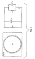
- The effect of electric fields on biological cells is not simply dependent on the magnitude of the applied electric field, but also on its duration. This can be understood by considering a model for the electrical equivalent circuit of the cell, shown schematically in
Fig. 1 . The model shown inFig. 1 does not take the effect of structures inside the cell into account. The cell (in suspension) is modeled by a resistance and capacitance. For a pulse duration which is long compared to the dielectric relaxation time of the suspension, the capacitive component of the suspension impedance can be neglected. For many cell suspensions and seawater (i.e., aqueous solutions with relatively high ionic strengths) the dielectric relaxation time is on the order of nanoseconds. The cell membrane can be modeled as capacitor, the cytoplasm as a resistor. The outer membrane contains channels which are affected by the applied voltage and allow flow of ions through the membrane, representing a leakage current. The voltage-gated channels can be modeled as variable, voltage-dependent resistors. - When a voltage pulse is applied to the cell, charges accumulate at the membrane and the membrane voltage is increased. The charging time constant of the cell membrane may be represented by equation (3):

with ρ1 being the resistivity of the suspending medium, e.g. water, ρ2 being the resistivity of the cytoplasm, C the capacitance per unit area, and r the cell radius (spherical cell). Using typical data for cells, the duration of the electric field pulses required to generate a potential difference of 1 V across the membrane can be calculated. The energy, W, dissipated in the suspension is given by:
Electric field and energy density are plotted inFig. 2 versus pulse duration for spherical cells ofradius 5 µm in a suspension with a resistivity of 50 Ωcm. The resistivity of the cytoplasm is assumed to be 100 Ωcm. The curves show a minimum at 150 nsec. This is the pulse duration where the stunning or killing of these kind of biological cells is predicted to be most effective. Experimental studies have reported which confirm the presence of such a minimum. - Schoenbach, K.H. et al., "The Effect of Pulsed Electric Fields on Biological Cells: Experiments and Applications", IEEE Transactions on Plasma Science, 25 (2), April 1997, pp. 285-292, describes experiments to explore the effect of pulsed electric fields with amplitudes in the range of 100 V/cm - 100 kV/cm on bacteria and aquatic nuisance species. The pulse duration was so short that heating of the biological matter could be neglected (abstract). In order to explore the effect of electric fields with pulse durations shorter than those used in previous experiments, pulse power systems were used which allowed high-voltage pulses of 60 ns, 300 ns and 2 µs duration to be generated. The load consisted of an aqueous suspension containing the test organisms. The medium was placed in commercially available cuvettes between two plane aluminium electrodes. With a minimum distance of 1 mm, maximum electric fields of 100 kV/cm could be obtained in the 60 and 300 ns systems. However, surface flashover at the suspension surface has limited the maximum field to about 80 kV/cm. There is no disclosure of an electrode array comprising at least one pair of needles capable of being inserted into tissue in vivo, the tissue containing target cells, and being capable of directing the ultrashort electric pulses to said target cells in vivo.
-
WO 98/47562 - Modifications of cells which lead to rupture of the cell membrane can lead to cell death via necrosis, a nonphysiological type of cell destruction. It would be advantageous to be able to initiate cell death via apoptosis in a selective manner. This would allow the destruction of cells without engendering the non-specific damage to surrounding tissues due to inflammation and scarring that is normally observed with necrosis. The ability to selectively modify cells in ways that lead to apoptosis could provide a new method for the selective destruction of undesired cells/tissue (e.g., tumor cells, fat cells or cartilage cells) while minimizing side effects on surrounding tissue.
- The present invention relates to an apparatus for destroying target cells according to claims. The ultrashort electric field pulse generally has at least a sufficient amplitude and duration when applied as a sequence of pulses to modify subcellular structures in the target cells in at least a transient fashion. The amplitude of individual pulses do not exceed the irreversible breakdown field of the target cells. The amplitude and duration of the ultrashort electric field pulse(s) are typically chosen so as to be insufficient to permanently alter permeability of surface membranes of the target cells, e.g., by rupturing the surface membranes.
- The use of electric field pulses with pulse durations and rise times substantially shorter than commonly used in conventional electroporation provides the potential for non-lytic methods of selective cellular injury or physiologic ablation that will be applicable to most cell types. For example, as suggested by the shrinkage observed in eosinophils exposed to one or more ultrashort electric field pulses, perturbing intracellular structures can lead to the induction of apoptosis. Localized induction of apoptosis could be used to sculpt tissues for cosmetic purposes or to selectively kill tumor cells, e.g., to selectively ablate tissues such as papillomas and nevi.
- The targeting of substructures of cells rather than cell membranes can have a utility in treatments involving the selective destruction of cells (e.g., tumor cells) without substantially damaging surrounding tissue(s). Most therapeutic applications of the pulsed electric field method require that the fields be applied to tissues rather than single cells. With the comparatively long pulses currently employed in such treatments (e.g., several hundred microseconds in length), however, the electric field seems to be less effective in treating tissue compared to single cells. It is known that although generalized tissue can be regarded as an aggregate of cells, with different types of cell-cell interconnections, tissue electroporation consists of electroporation of individual cells. There are two major differences between the electroporation of individual cells in a suspension and the electroporation of tissue. In tissue, the local extracellular electric field depends in a complicated way on the many neighboring cells. In addition, for tissues the ratio of the extra- to intracellular volume is usually small, just the opposite of most in vitro electroporation conditions. This means that if chemical exchange between the intra- and extracellular volumes is the main cause of cell stress, and therefore cell death, tissue electroporation with microsecond pulses may be intrinsically less damaging in vivo than most in vitro electroporation conditions. Since ultrashort pulses can affect only the interior of the cell, such pulses are expected to have roughly the same effect on tissues as on individual cells.
- Another advantage of using ultrashort pulses of the type employed in the present method is the low energy of these pulses. Although the electrical power of the pulses may be many megawatts, the energy of these pulses is often so low (due to their extremely short duration) that any thermal effects on cells can be neglected. The present pulse power method is thus a "cold" method which can allow modification of cells via electrical effects without creating any substantial related thermal effects. For example, the thermal effects associated with the pulses employed in the present method typically only generate temperature increases in the bulk medium or tissue on the order of 1-2°C. The ability to electrically modify cells in a "cold" manner is particularly useful where the intent is to selectively modify subcellular structures within a target cell without substantially effecting the cell membrane.
- The apparatus according to the invention includes a pulse generator capable of producing an ultrashort electric pulse output and a delivery system capable of directing the electric pulse output to target cells, e.g., capable of selectively directing the electric pulse output to targeted cells in vivo in a manner which avoids causing substantial injury to the surrounding tissue.
-
-
Fig. 1 depicts an electrical equivalent circuit of a cell in suspension. -
Fig. 2 is a graph showing the electric field required to charge a cell surface membrane to 1 V and corresponding energy density versus pulse duration. -
Fig. 3 shows an HL-60 leukemia cell and a simplified electrical equivalent circuit of a cell containing a nucleus. -
Fig. 4 shows voltage-time curve for modeling of application of 60 nsec and 6 µsec electric field pulses to a theoretical cell. The dotted line shows the applied voltage pulse, the dashed line shows calculated voltage across the surface membrane, the heavy solid line shows the voltage across intracellular membranes. -
Fig. 5 shows microscopic examinations (10X magnification) of stained human neutrophils at 0, 10, 20 and 30 minutes after being subjected to a 60 nsec, 60 kV/cm electric field pulse ("A4"), not using an apparatus according to the invention, in comparison to an untreated control (Fresh). -
Fig. 6 shows microscopic examinations (10X magnification) of stained human neutrophils at 0, 10, 20 and 30 minutes after being subjected to a 300 nsec, 40 kV/cm electric field pulse ("B6"), not using an apparatus according to the invention in comparison to an untreated control (Fresh). -
Fig. 7 shows microscopic examinations (160X magnification) of stained human neutrophils immediately after being subjected to a 60 nsec, 60 kV/cm electric field pulse ("A42"), 300 nsec, 40 kV/cm electric field pulse ("B6"), or 300 nsec, 60 kV/cm electric field pulse ("B8"), not using an apparatus according to the invention. -
Fig. 8 shows microscopic examinations (280x magnification) of stained human neutrophils immediately after being subjected to a 60 nsec 60 kV/cm electric field pulse, (A4) or 300 nsec 40 kV/cm electric field pulse (B6), not using an apparatus according to the invention. -
Fig. 9 shows microscopic examination of myeloperoxidase stained human neutrophils (280x magnification) immediately after being subjected to a 60 nsec, 60 kV/cm electric field pulse, (A4), 300 nsec, 40 kV/cm electric field pulse (B6), or 300 nsec, 60 kV/cm electric field pulse (B8), not using an apparatus according to the invention, in comparison to untreated control (FRESH). -
Fig. 10 is a graph of the nuclear area (in pixels) of cells after being subjected to a 60 nsec, 60 kV/cm electric field pulse, (A4), 300 nsec, 40 kV/cm electric field pulse (B6), or 300 nsec, 60 kV/cm electric field pulse (B8), not using an apparatus according to the invention, in comparison to untreated control (FRESH). -
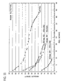
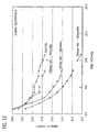
Fig. 11 is a graph of absolute density at distances from its origin for human neutrophils after 2 hours of migration in agarose filled plates in response to bacterial fMLP stimulation; the neutrophils were subjected to a 60 nsec, 60 kV/cm electric field pulse, (A4), 300 nsec, 40 kV/cm electric field pulse (B6), or 300 nsec, 60 kV/cm electric field pulse (B8), not using an apparatus according to the invention, in comparison to untreated control (FRESH). -
Fig. 12 is a graph of absolute density at distances from its origin for human neutrophils after 2 hours of unstimulated migration (control buffer) in agarose filled plates; the neutrophils were subjected to a 60 nsec, 60 kV/cm electric field pulse, (A4), 300 nsec, 40 kV/cm electric field pulse (B6), or 300 nsec, 60 kV/cm electric field pulse (B8), not using an apparatus according to the invention, in comparison to untreated control (FRESH). -
Figure 13 is a graph of the mean distance migrated by human neutrophils under unstimulated (control buffer) and stimulated (bacterial FMLP) conditions after being subjected to a 60 nsec, 60 kV/cm electric field pulse, (A4), 300 nsec, 40 kV/cm electric field pulse (B6), or 300 nsec, 60 kV/cm electric field pulse (B8), not using an apparatus according to the invention, in comparison to untreated control (FRESH). -
Fig. 14 is a graph showing the effect of exposure of HL-60 promyelocytic leukemia cells in logarithmic growth phase to electric field pulses of varying duration (60 nsec, 2 µsec, 10 µsec, or 200 µsec). -
Fig. 15 is a graph showing the effect of exposure of HL-60 promyelocytic leukemia cells in stationary growth phase to electric field pulses of varying duration (60 nsec, 2 µsec, 10 µsec, or 200 µsec). -
Fig. 16 is a graph showing the percentage apoptosis of HL-60 cells as a function of time after being subjected to IEM pulses at 60 nsec, 60 kV/cm (A4), 300 µsec, 40 kV/cm (B6) or 300 µsec, 60 kV/cm (B8). -
Fig. 17 is a graph showing the percentage necrosis of HL-60 cells as a function of time after being subjected to IEM pulses at 60 nsec, 60 kV/cm (A4), 300 µsec, 40 kV/cm (B6) or 300 µsec, 60 kV/cm (B8). -
Fig. 18 is a graph showing the percentage apoptosis of HL-60 cells as a function of time after being subjected to IEM pulses at 60 nsec, 60 kV/cm (A4), 300 µsec, 40 kV/cm (B6) or 300 µsec, 60 kV/cm (B8). -
Fig. 19 is a graph showing the percentage necrosis of HL-60 cells as a function of time after being subjected to IEM pulses at 60 nsec, 60 kV/cm (A4), 300 µsec, 40 kV/cm (B6) or 300 µsec, 60 kV/cm (B8). -
Fig. 20 depicts a schematic of an apparatus for modifying cells, not according to the invention, which includes a line type pulse generator with a laser triggered spark gap switch. -
Fig. 21 is a graph depicting its shape of an exemplary electric field pulse (as a plot of voltage versus time) which can be employed in the present methods. -
Fig. 22 is a graph showing the Fourier spectrum (as a plot of amplitude in V/Hz versus frequency) of the electric field pulse shown inFig. 21 . -
Fig. 23 is a graph (voltage versus time) depicting the shape of an exemplary 60 nsec pulse in comparison to a 10 microsecond (10 µsec) pulse. -
Fig. 24 is a graph depicting the Fourier spectrum (as a plot of amplitude in V/Hz versus frequency) for the 60 nsec and 10 µsec pulses shown inFig. 23 . -
Fig. 25 is graph showing a voltage versus time tracing for an ultra-short electrical pulse produced by the ultra-short pulse generator shown in the inset panel; the resulting electrical pulse is nearly rectangular in shape and reaches a maximum voltage in the 5-6 kV range, which when applied in a cell suspension via electrodes 0.1 cm apart, using an aparatus not according to the invention, provides electrical intensities in the 50-60 kV/cm range. -
Fig. 26 shows microscopic examination of human eosinophils stained with calcein (right) and by modified Wright-Giemsa stain (left). Top panels show untreated (control) eosinophil appearance, with negative staining intracellular granules within calcein-stained eosinophils. Following 3 (middle panels) or 5 (lower panels) pulses (60 nsec, 53 kV/cm), subsets of calcein-labeled eosinophils develop brightly staining intracellular granules while retaining their cytoplasmic calcein labeling, which indicates loss of membrane integrity in the brightly stained granules without loss of surface membrane integrity (i.e., retention of the cytoplasmic calcein staining). -
Fig. 27 shows microscopic examination of the effects of Triton X-100 treatment on free calcein staining of eosinophil granules; UPPER ROW: Wright-Giemsa stained (above) and fluorescent (below) images of eosinophils (left), calcein-AM (1 µM) stained eosinophils (center), and eosinophils incubated for 5 minutes in 0.001% Triton X-100 + 1 uM free calcein (right); BOTTOM ROW: Wright-Giemsa stained (above) and fluorescent (below) images of eosinophils treated with 1 µM free calcein + 0.005% Triton X-100 for 5 minutes (left), eosinophils treated with 0.01 % Triton X-100 + 1 uM free calcein for 5 minutes (center) and eosinophils incubated in 0.05% Triton X-100 + 1 µM free calcein for 5 minutes (right). -
Fig. 28 shows the lines of an electric field generated in tissue between a pair needle electrodes inserted into the tissue. -
Fig. 29 shows a hexagonal array of positions that can be used to apply ultrashort electric field pulses to a targeted area of tissue in vivo. - In the simple equivalent circuit shown in
Fig. 1 , the cell was modeled as a homogeneous, conductive medium surrounded by a dielectric membrane. Taking substructures in cells into account, such as the cell nucleus in eukaryotic cells, requires a more complex model of the equivalent circuit. HL-60 Leukemia cells can be used to demonstrate the complexity of structures inside the cell. The nucleus is clearly visible as are smaller substructures within it, e.g., nucleoli. The substructures can be modeled by treating the membrane surrounding the nucleus as a capacitor and the interior of the nucleus as a resistor, both elements in series and in parallel to the resistance which describes the cytoplasm in the first, simplified, equivalent circuit (see, e.g.,Fig. 3 ). Similarly, the nucleoli can also be described by an additional capacitor resistor arrangement in parallel to the nucleus resistance. - Basic electrical circuit principles indicate that low frequency electric fields will affect mainly the larger capacitance, that is the outer membrane. With increasing frequency, the outer membrane, however, will be effectively shorted out, and the applied voltage will appear across the inner (nucleus) membrane. This model predicts that at frequencies around 1 MHz, the applied voltage should appear mainly across the membrane of the nucleus, rather than across the outer membrane. This means that shorter pulses with higher frequency components would be expected to affect the nucleus of a cell rather than the cell membrane.
- Assuming that the diameter of target intracellular structures, d, is small compared to the cell diameter, and that the structures are located in the center of the cell, the voltage across the intracellular structure, Vis, can be modeled according to the equation:

where p is is the resistivity of the target intracellular structure. The charging of the intracellular membrane is predicted to occur with a time constant, T is:
- The voltage across the intracellular structure membrane, Vism, is consequently given as:

where u(0) and u(T) are stepfunctions at t=0 and t=T. - The temporal development of the applied voltage, the voltage across the surface membrane and that across the intracellular structure membrane (equ. 7) is shown in
Figure 4 for the cellular parameters D=0 µm, d=5 µm, p c=p n=100 Ωcm, cm=1µF/cm2, cn=0.5 µF/cm2, and a pulse duration of T=60 nsec. In this instance, a rectangular pulse is applied, while in experimental situations, the pulse is more typically trapezoidal. The value for the capacitance of the outer cell surface membrane has been reported in published work (see, e.g., Schwan, Biophysik, 1, 190 (1963)) and the capacitance of intracellular structures is assumed to be either the same or half of this value, depending on the structure of the specific intracellular membrane. The nucleus is surrounded by two lipid bilayer membranes that make up the nuclear envelope, whereas other intracellular structures (e.g., intracellular granules) may have only one lipid bilayer membrane surrounding them. - From this simple theoretical model, a number of conclusions can be drawn:
- 1. The voltage across the intracellular membrane may reach values on the same order as the voltage across the outer membrane if the pulse duration is larger than the charging time of the intracellular membrane and the pulse rise time is small compared to this charging time. The importance of the second condition can be illustrated by considering the electrical response of a cell to two pulses with the same electric field, but quite different rise times (and durations). The electrical pulses are presumed to be similar in shape but the ultra-short (60 nsec) duration pulse has rise and fall times of 10 nsec, while the longer pulse (6 µsec) has rise and fall times of 1 µsec. If the cell dimensions, capacitances and resistivities are the same, the short, fast rise-time pulse results in voltages across the intracellular and surface membranes that are comparable for both membranes, while the longer pulse with the microsecond rise-time results in almost negligible voltage across intracellular membrane. The voltage across the outer membrane for the longer pulse, however, reaches the value of the applied voltage, favoring electroporation of this membrane. This effect has been used in medical applications where pulses in the temporal range of tens of microseconds to milliseconds are used to facilitate drug and gene delivery into cells.
- 2. To reach voltages in excess of 1 volt across intracellular membranes, electric field amplitudes in the megavolt/m range are required on a time scale of the charging time of the intracellular membrane. For intracellular structures with characteristic dimensions of µm, membrane capacitances on the order of µF/cm2, and cytoplasm resistivities of 100 Ωcm, the charging time (equ. 6) is less than 10 nsec. The required rate of change of the electric field intensity is consequently dE/dt > 1014 volt/(meter second). Only if both conditions are satisfied (i.e., large electric field amplitude plus extremely fast rates of change in the electric field), can intracellular effects be expected.
- 3. The voltage across intracellular membranes is expected to be almost linearly dependent on the diameter of the intracellular structure. Stronger effects at larger internal structures would therefore be expected with the same electrical parameters.
- Reaching a critical voltage across the intracellular membrane is a necessary but not sufficient condition for "intracellular electromanipulation" ("IEM"). In order to change the structure of the membrane, e.g., open membrane defects to a size that allows passage of macromolecules through them, the critical voltage needs to be applied long enough to allow expansion of the defects to appropriate size. Estimates of the voltage required to achieve such effects at the surface membrane have been reported, but no such estimates exist for intracellular membranes. The model described here is therefore only providing necessary conditions for the onset of electric field dependent effects on intracellular membranes, and does not describe the specific processes occurring within the membranes. Nonetheless, this analysis clearly illustrates that reducing the pulse duration, or more precisely, reducing the pulse rise time to values less than the charging time for intracellular membranes, and increasing electric field intensities to megavolt/m range should allow preferential targeting of intracellular membranes. The experimental work described herein establishes that at least in certain cases, the application of a sequence of multiple ultrashort pulses within a relatively short time period can amplify the effect on intracellular substructures without causing substantial defects in the outer surface membrane.
- The present method typically employs ultrashort electric field pulses having sufficient amplitude and duration to modify subcellular structures in the target cells, at least when applied as a sequence of ultrashort pulses within a relatively short time period, e.g., a sequence of 3-5 ultrashort pulses within a time interval of 10 seconds or less. The amplitude and duration of each ultrashort electric field pulse can be chosen so that it is insufficient to alter permeability of surface membranes of the target cells, e.g., by inducing pores in the cell membranes. The target cells are present as part of a tissue. Each ultrashort electric field pulses typically has a pulse duration of no more than about 1 microsecond and an amplitude of at least about 20 kV/cm. Characterized in a different fashion, the ultrashort electric field pulses typically have a pulse duration of no more than about 1 microsecond and provide a total energy density of at least about 75 mJ/cc. Preferably, the ultrashort electric field pulses provide total energy density of no more than about 10 J/cc. More typically, the total energy density provided by each ultrashort electric field pulse is about 75 mJ/cc to about 2,000 mJ/cc and, preferably, about 100 mJ/cc to about 1,000 mJ/cc, In instances where extremely short pulses are applied, e.g., pulses having a duration of about 10 nanoseconds or less, the total energy density provided by the electric field pulse may only be on the order of about 10 to 20 ml/cc. In addition to having short durations, the electric field pulses used in the present methods commonly have rise times of 50 nsec or less.
- The amplitude of an electric field (the applied voltage divided by distance between electrodes) pulse is generally at least about 20 kV/cm, but should not exceed the breakdown field of the tissue which includes the target cells. The breakdown field increases with decreasing pulse duration, and can be experimentally determined. Under the conditions commonly employed in the present method, however, the breakdown field does generally not exceed 500 kV/cm. Electric field pulses employed in the present methods which have durations of 10 to 500 nsec typically have amplitudes of about 20 kV/cm to about 300 kV/cm.
- To minimize the potential effects on the bulk temperature of the medium ("thermal effects"), the electrical field pulses generally have a rapid rise time and short duration. The pulses should preferably be less than one microsecond, but more than 100 picoseconds in duration. A common pulse duration is about 1 nanosecond to about 500 nanoseconds, with pulses typically having a duration, of about 10 to a 300 nanoseconds. The optimum pulse duration will vary depending on the cell type, tissue type and desired treatment, among other factors. The pulse should be preferentially rectangular or trapezoidal, but other pulse shapes may also used. For example, in order to open both the outer and inner cell membranes, an intense short pulse might be combined with a less intense longer pulse. Other examples of suitable pulse shapes include exponential decaying pulses, unipolar pulses and bipolar pulses.
- The rise time of the ultrashort electric field pulse is typically no more than about 20% and, preferably, no more than about 10% of the pulse duration. For example, if the pulse duration is about 100 nanoseconds, the rise time of the pulse is preferably about 10 nanoseconds or shorter. For pulses with pulse durations of about 400 nanoseconds or longer, the pulse rise times of about 30-40 nanoseconds are common. With pulses having extremely short durations, e.g., one nanosecond or less, the rise time is often a greater percentage of the pulse duration. For example, pulses with a duration of less than one nanosecond, can commonly have a rise time which is up to about 50 % of the pulse duration.
- The duration, rise time and the frequency distribution of the Fourier transform of the pulse are related.
Figure 24 shows the Fourier spectrum of a short pulse (60 nsec) which extends to the 10 MHz range and for a long pulse (10 microsec) which extends up to the 100 KHz range. With increasing frequency (i.e., decreasing pulse rise time), the outer surface membrane of the target will be effectively shorted out, and the applied voltage will appear across the inner (nucleus) membrane. This behavior is shown inFig. 4 , where the voltage across the surface (outer) membrane and that across the nucleus membrane is plotted versus frequency.Fig. 4 predicts that at frequencies around 1 MHz, the applied voltage should appear mainly across the membrane of subcellular structures, such as the nucleus, rather than across the outer surface membrane. Electric field pulses with duration of less than about 1 microsecond and rise times of 40 nanoseconds or less have Fourier transforms which include frequencies above 1 MHz with substantial amplitudes. - The Fourier spectrum of the pulses which are employed in the present methods can include frequencies with substantial amplitudes up to about 1 GHz. Typically, the pulses employed in the present methods have Fourier spectra which include frequencies above 1 MHz with amplitudes greater than 50% of the maximum voltage in the spectrum (referred to hereinafter as greater than "VMAX/2"). Preferably, the Fourier spectra of the pulses includes frequencies between 5 to 50 MHz with amplitude greater than VMAX/2. For example, a 60 nanosecond rectangular pulse such as depicted in
Fig. 21 has a Fourier spectrum which includes frequencies with amplitude greater than VMAX/2 up to about 10 MHz. In contrast, the Fourier spectrum of a 10 microsecond rectangular pulse only has frequencies of this amplitude up to about 200-500 kHz (see comparison inFigs. 23 and 24 ). - As indicated above, to modify subcellular structures in target cells it may be advantageous to apply a series of ultrashort electric field pulses within a relatively short time interval. For example, it has been found that the application of a sequence of 3 to 5 ultrashort electric field pulses (e.g., trapezoidal pulses with durations of 10-300 nsec and amplitudes of about 25 to 300 kV/cm) may be more effective at modifying intracellular substructures than a single pulse of the same amplitude and duration (see Example 9). For example, the application of a multipulse sequence with a roughly one second interval (delay) between pulses can rupture granules within eosinophils without significant damage to the outer cell membrane. Where multipulse sequences are employed in the present methods, the time interval between subsequent pulses may vary over a wide range, e.g., between 1.0 millisecond and 100 seconds. As another example, multiple pulse sequences with time interval between pulses of about 0.1 - 3 seconds are quite suitable for initiating apoptosis. Although larger numbers of pulses may be employed, the multipulse sequences utilized in the present methods typically include up to about 20 pulses, which are generally spaced at regular time intervals. Suitable results can often be obtained for certain types of cells (e.g., eosinophils, neutrophils and T-lymphocytes) by applying 3-5 ultrashort electric field pulses within a relatively short time period, e.g., within a time period no longer than about 5 to 10 seconds. As indicated above, the amplitude and duration of the ultrashort electric field pulse are typically chosen so that the sequence of pulses does not permanently alter permeability of surface membranes of the target cells, e.g., by rupturing the surface membranes.
- The present method may be used to modify a variety of cells, For example, the target cells may be any of a variety of common cells, such as fat cells, bone cells, vascular cells, muscle cells, cartilage cells and the like. In some instances, the technique may be used to selectively modify certain types of cells in the presence of other cells. For example, the parameters of the present method may be adjusted to selectively induce apoptosis in tumor cells in vivo (e.g., carcinoma cells, sarcoma cells, or papilloma cells) without substantially affecting normal cells in surrounding tissue. As another example, the technique may be utilized to selectively destroy eosinophils in a mixture including eosinophils and neutrophils (see, e.g., Table II in Example 4 herein). The experiments described herein indicate that the present techniques may be used to selectively modify faster growing cells in the presence of slower growing cells (e,g., cells in stationary phase). In other instances, the selectivity may be simply based on spatially limiting the application of the ultrashort electric field pulse(s). For example, by using an appropriate configuration of electrodes, cells within a predetermined area of tissue may be selectively modified in vivo (e.g., through initiation of apoptosis) without altering cells in the immediately surrounding tissue. Devices which incorporate such electrode configuration are currently employed with conventional electroporation pulses (pulses with µsec duration) to enhance the delivery of therapeutic drugs to cells within a predetermined area.
- The apparatus of the invention may be used in a method that can be used to initiate apoptosis in target cells by applying at least one ultrashort electric field pulse with a pulse duration of no more than about 1 microsecond to the target cells. In such instances, electric field pulse commonly provides a total energy density of at least about 75 mJ/cc, although pulses with lower energy may be employed, in particular where the pulse has an extremely short duration and a relatively high amplitude or where sequences of multiple pulses are applied to the target cells within a relatively short time interval, e.g., with a spacing of 1-2 seconds between succeeding pulses.
- Upon choice of the correct parameters, the present method can be employed to selectively destroying target cells in a mixture including the target cells and a second type of cells. For example, the method can be used to selectively destroy eosinophils in a mixture including eosinophils and neutrophils.
- The present method typically employs an apparatus for intracellular electro-manipulation which includes a pulse generator and a delivery system adapted to direct the electric pulse output to target cells. The pulse generator includes a pulse forming network and a high voltage switch. The pulse forming network may be a high voltage cable, a strip-line, or a pulse forming network constructed of individual capacitors and inductors in a transmission line arrangement. The high voltage switch can suitably be a gaseous, liquid or solid state switch. The energy in the pulse forming network may be stored capacitively, which requires a closing switch to release a pulse, or inductively, which requires an opening switch to release a pulse. Upon triggering of the switch, an electrical pulse is launched into the load, i.e., the target cells in tissue form. The switch can be triggered by a variety of common methods, e.g., optically or electrically. The latter can be accomplished by employing a third electrode or by overvolting the switch. An example of a suitable cable pulsed power system, designed to generate ultrashort pulses of the type employed in the present method is shown in
Figure 20 .Figure 21 shows a typical shape of a pulse employed in the present methods and the corresponding Fourier spectrum of the pulse is shown inFigure 22 . The electrical field pulses can be varied in length ("duration") by changing the pulse forming network, such as by reducing or increasing the length of the cable or stripline, or by using a switch which can be closed and opened. One specific example of an apparatus suitable for modifying cells by intracellular electro-manipulation is described in Example 10 herein. - The "load," which includes the target cells in tissue is located between two or more electrodes. These electrodes may be solid material, wires or combinations thereof. One (set of) electrode(s) is connected to the high voltage connection of the pulse generator, and a second (set of) electrode(s) is connected to the ground connection of the pulse generator in a suitable manner, e.g., via a second stripline or high voltage cable. The electrode material is a conductor, most commonly metal.
- A typical ultrashort pulse electric field generator ("USPEF generator") includes a distributed pulse forming network, a switch to allow rapid transfer of electrical energy into the load, and the load itself (see, e.g.,
Figure 25 , inset). If such a pulse-forming network is charged up to 18 kV, and then released, this charge can produce an almost rectangular ultra-short duration pulse (seeFigure 25 ), which when applied to a 10 Ω load, produced a maximum voltage of 9 megavolts. The corresponding electric field intensity between two electrodes separated by 1.4 mm is 90 kV/cm. The maximum electrical power, V2/R, which can be achieved with these conditions is 8.1 MW, while the energy (power x pulse duration) transferred into the load is only 0.49 Joule. For a 100 µL volume of cell suspension, the energy density is consequently 4.5 J/cc. This energy transfer results in a calculated maximum temperature increase of only about 1°K for a single pulse. - In one particularly useful embodiment, the apparatus includes a pulse generator capable of producing ultrashort electric pulses and a delivery system capable of selectively directing the electric pulse output to targeted cells in vivo, e.g., capable of selectively directing the electric pulse output to tumor cells in vivo in a manner which avoids causing substantial injury to the surrounding tissue. The pulse generator in an apparatus of this type is typically capable of generating electric pulses having a duration of 1 to 500 nanoseconds and amplitudes of at least 10 kV/cm. The delivery system includes one or more pairs of electrodes capable of being inserted into tissue in vivo in the form of an array of needle electrodes. In another configuration, delivery system includes at least one electrode which is an component of a catheter. Basic configurations for such delivery systems are described in
WO-A-97/49 450 - The following examples are presented to illustrate the present invention and to assist one of ordinary skill in making and using the same. The examples are not intended in any way to otherwise limit the scope of the invention.
- Experiments were conducted to determine the effects of ultrawide band, low energy, short duration electric pulses (Intracellular Electro-Manipulation or "IEM") to induce a delayed, time-dependent and/or energy/power-dependent cell death in human neutrophils. Groups of cells were subjected to single rectangular pulses having the following parameters and compared to untreated control cells: A4 - 60 nsec, 60 kV/cm; B6 - 300 nsec, 40 kV/cm; and B8 - 300 nsec, 60 kV/cm.
- Cells were stained with calcein-AM, a green fluorescent probe that stains the cytoplasm of live, intact cells, and then exposed to the various IEM pulses. Immediately after exposure to IEM, the cells were stained with ethidium bromide homodimer (EtBr), a membrane non-permeable red fluorescent probe that stains the nucleus of cells that exhibit plasma membrane damage. The cells were centrifuged onto glass slides (cytospin). The cells were observed under conditions for calcein (left panel) or EtBr (middle panel) fluorescence (see
Figs. 5-7 ). Images were captured, and the fields marked. The cells were then stained with Wright stain (right panel), the same fields were observed, and images were captured under conditions for light microscopy Images were observed at 10X magnification. - Freshly isolated human neutrophils exhibit a limited life span and undergo cell death during in vitro culture. At time 0 (T0) after IEM, only a small percentage of cells (2-5 %) exhibits EtBr fluorescence, indicating few membrane-ruptured cells (see
Fig. 5a ). After 1 hour, a small increase in the number of ruptured cells is indicated. The cells appear as small pinkish (cytoplasm) circles with dark purple dots (nuclei) within. - Under A4 pulse parameters at T0 after IEM, no increase in the number of EtBr fluorescent cells is observed, indicating that the cells are still intact (see
Fig. 5 ). A small time-dependent increase in the number of neutrophils exhibiting EtBr fluorescence occurs, indicating small increasing cell death. At T30, there is a small increase in the number of dead cells compared to T30 control cells. - Under B6 pulse parameters at T0 after IEM, no increase in the number of EtBr fluorescence is observed, indicating that the cells are still intact (see
Fig. 6 ). However, a more rapid increase in the number of EtBr fluorescent cells occurs with time. Notice in B6, T20 and T30 (middle panel) there are increases in the percentage of dead cells and in the right panel, increases in the number of lysed, ruptured cells are evident. These appear as pinkish smears (spilled cytoplasm) around dark nuclei. Similar results were observed with the B8 pulse. - The ability of IEM to alter subcellular structures without disrupting the plasma membrane was examined. Protease-containing vesicles within the neutrophil were "modified" before the nucleus was "modified," thereby demonstrating selectivity for modifying subcellular structures. Method: IEM parameters included sham or control (fresh), A4 (60 nsec, 60 kV/cm), B6 (300 nsec, 40 kV/cm), and B8 (300 nsec, 60 kV/cm). All exposures were at immediately after IEM exposure (T0) and images were at 160X magnification (
Fig. 7 ) or 280X magnification (Figures 8 and9 ). - Results:
Figure 7 . Under A4 pulse parameters at T0 after IEM, no increase in the number of EtBr fluorescence is observed, indicating that the cells are still intact. A4 neutrophils shown are intact and exhibit morphology similar to control cells. The cytoplasm exhibits relatively even fluorescence (left panel) and Wright staining (right panel). Nuclear changes are minimal (dark purple lobed or irregular staining nuclei, surrounded by lighter stained cytoplasm). - In contrast, under B6 pulse parameters at T0 after IEM, the cytoplasm exhibits uneven calcein fluorescence with "pores" or "holes" showing the absence of fluorescence (left panel). Wright staining (right panel) also indicates "pores" or "holes". Nuclear staining appears somewhat uneven, with beginning evidence of "pores" or "holes".
- Under B8 pulse parameters at T0 after IEM, cytoplasmic staining is nearly gone and nuclear staining exhibits significant "pores" or "holes" (right panel). The B8 control (left panel, Wright stain) shows neutrophils not exposed to IEM (normal), but prepared at the same time as B8 IEM exposed neutrophils.
- B5 (right panel, Wright stain) shows IEM conditions (300 nsec, 30 kV/cm) between A4 and B6. Note how "pores" or "holes" begin to become evident in the cytoplasm. The B5 control (left panel, Wright stain) shows neutrophils not exposed to IEM (normal), but prepared at the same time as B5 IEM exposed neutrophils.
Figure 8 . Neutrophils from A4 and B6 pulse parameters are shown at higher magnification (280X) to more clearly show the cytoplasmic characteristics. The "pores" or "holes" are present in B6, but not A4.
Figure 9 . Neutrophils are shown after myeloperoxidase staining, which stains neutrophil vesicles that contain proteases used for killing bacteria. Myeloperoxidase staining at T0 in fresh and A4 IEM parameter appear relatively granular, indicating the presence of numerous small protease-containing vesicles. Under B6 IEM parameters, the staining is more diffuse, indicating the presence of vesicle rupture. Under B8 IEM parameters, the staining is nearing gone, indicating that nearly all of the vesicles have bee ruptured with the higher energy / power conditions. - The ability of IEM to induce nuclear shrinkage in neutrophils and HL-60 cells was examined. Nuclear shrinkage is a typical characteristic of cell death by apoptosis (programmed cell death).
Method: IEM parameters include sham or control (fresh), A4 (60 nsec, 60 kV/cm), B6 (300 nsec, 40 kV/cm), and B8 (300 nsec, 60 kV/cm). Cells were stained with Wright stain immediately after being subjected to the IEM pulse, nuclei were set to gray scale and pixel area was determined. Nucleus sizes from 30 to 42 cells were determined and each one plotted according to pixel area.
Result: Nuclei from neutrophils exposed to all three IEM parameters are significantly smaller than control cells (seeFigure 10 ). The mean nuclear area in pixels for each condition (IEM conditions) were determined. In contrast to the control which had a mean pixel area of 15,152 ± 338 (30 determinations), the cells subjected to an IEM pulse had the following mean pixel areas: - A4 - 11,871 ± 324 (30 determinations);
- B6 - 13,814 ± 332 (42 determinations); and
- B8 - 12,147 ± 299 (35 determinations).
- The IEM parameters required to induce cell death in different cell types were examined. Eosinophils were observed to be more sensitive to IEM than neutrophils. Method: IEM parameters included sham or control (fresh), A4 (60 nsec, 6kV), B6 (300 nsec, 4kV), and B8 (300 nsec, 6kV) as well as additional IEM parameters as indicated. Human neutrophil preparations include some contaminating eosinophils, which are more abundant during hay fever/allergy seasons (at the time of these studies). The number of eosinophils was determined as a percentage of the number of neutrophils by morphology and cell counting under light microscopy.
Result: As the energy/ power of IEM is increased, the number of eosinophils present immediately after IEM is significant decreased from the cell population without significant losses of neutrophils (see Table I).TABLE I Slide # nsec KV/cm Neutrophils eosinophils %eosinophil Fresh 0 0 183 17 9.0 A1 60 30 194 6 3.0 A2 60 40 190 10 5.0 A3 60 50 190 10 5.0 A4 60 60 192 8 4.0 B5 300 30 188 12 6.0 B6 300 40 200 0 0.0 B7 300 50 200 0 0.0 B8 300 60 199 1 0.5 B9 300 ~ 80 200 0 0.0 - IEM alters neutrophil function without disrupting the plasma membrane. The effects on chemotaxis are different than the effects on unstimulated movement, suggesting a selective effect on neutrophil function.
Method: IEM parameters included sham or control (S), A4 (60 nsec, 60 kV/cm), B6 (300 nsec, 40 kV/cm), and B8 (300 nsec, 60 kV/cm). Cell were exposed to various IEM parameters, placed into wells cut in agarose fill plates, and then induced to crawl in response to control buffer (unstimulated movement) or to a chemical stimulant from bacterial fMLP (chemotaxis). After two hours of movement under agarose, the cells were stained and the absolute density at distances from the origin and mean distance migrated by the neutrophil population were determined by image analysis.
Result: For chemotaxis, there is a direct relationship between energy/power and inhibition of chemotaxis function; higher energy/power results in increases in chemotaxis inhibition as determined by the absolute density at distances from the origin in each (Fig. 11 ) and mean distance migrated (Fig. 13 ). There were 61.6%. 62.4%, and 87.8 % inhibition with parameters A4, B6, and B8, respectively, as a percentage of the migration of the bacterial fMLP stimulated control, as determined by the mean distance migrated by the neutrophil population (see Table II).TABLE II Conditions Chemotaxis % Inhibition of Chemotaxis Unstim. Movement Controls 14.77 - 3.18 60 nsec, 180 mJ/ml 5.67 61.6 1.65 300 nsec, 400 mJ/ml 5.56 62.9 1.98 300 nsec, 900 mJ/ml 1.86 87.8 2.54 - In contrast, for unstimulated movement there appears to be little effect between energy/power and inhibition of movement (see
Figs. 12 and13 ). The relationship between energy/power of the pulse and inhibition of unstimulated movement is unclear. With parameters A4, B6, and B8, respectively (see Table II), pulsed unstimulated cells showed small amounts of inhibition of migration with respect to the unstimulated control. - The effect of IEM on the proliferation of HL-60 cells in logarithmic growth phase was examined. Proliferation was inhibited by IEM as a function of pulse duration. These results indicate a potential for IEM to selectively kill rapidly growing cells, e.g., tumor cells,
Method: HL-60 cells were maintained at a density of 100-300,000 cells / ml, conditions for maximal cell doubling time (10-14 h, log phase growth). Cells were exposed to various IEM parameters by maintaining a constant energy exposure (200-250 mJ/ml) at different pulse durations as indicated. The cells were then diluted to 50,000 cells/ml and the viable cell number (cells that excluded trypan blue; i.e. live cells) was determined after 0, 24, and 48 hours using a hemocytometer under light microscopy.
Results: The number of viable cells was not different from control immediately after treatment with IEM (seeFig. 14 ). Twenty-four hours after IEM, treated cells grew at rates similar to control, except under the condition of the longest pulse time (200 µsec). After 48 hours, the proliferation rate of cells exposed to a pulse of 0.06-10 µsec began to decrease, indicating more death events than proliferation events. Cells exposed to a pulse of 200 µsec increased their proliferation rate to near the control rate. - The effect of IEM on the proliferation of HL-60 cells in the stationary growth phase was examined. Growth was enhanced by IEM as a function of pulse duration. These results indicate a potential for specific IEM conditions to promote the growth of slowly dividing cells.
Method: HL-60 cells were maintained at a density of 1-3,000,000 cells/ml for 3-5 days, conditions for minimal cell doubling time (near stationary phase growth). Cells were exposed to various IEM parameters by maintaining a constant energy exposure (1.7-1.9 J/ml) at different pulse durations as indicated. The cells were then diluted to 50,000 cells/ml and the viable cell number (cells that excluded trypan blue; i.e. live cells) was determined after 0, 24, and 48 hours using a hemocytometer under light microscopy. Results: The number of viable cells was not significant different from control immediately after treatment with IEM (seeFig. 15 ). After 24 and 48 hours, the proliferation rates were greater than control for cells exposed to a pulse of 0.05 or 200 µsec. The proliferation rate was less than control for cells exposed to a pulse of 10 µsec. A pulse duration minimum is observed to inhibit the proliferation of slowly growing cells. - The experiments described in Example 3 above (see
Figure 10 ) demonstrated that IEM pulses can result in the shrinkage of the nucleus, a hallmark of apoptosis. New data using more specific and definitive markers for apoptosis as well as necrosis, support the hypothesis that IEM pulses induces apoptosis in neutrophils and HL-60 cells. Method: IEM parameters include sham or control (fresh), A4 (60 nsec, 60 kV/cm, 216 mJ/cc), B6 (300 nsec, 40 kV/cm, 480 mJ/cc), and B8 (300 nsec, 60 kV/cm, 1.08 J/cc). Neutrophils or HL-60 cells were incubated with Annexin-V-FITC and Ethidium bromide homodimer ("EtBr"). Annexin-V-FITC binding was used as a quantitative apoptosis marker. Annexin-V exhibits calcium-dependent binding to phosphatidylserine. While phosphatidylserine is typically restricted to the inner leaflet of the cell membrane in normal cells and is therefore inaccessible to Annexin-V in solution, apoptotic cells express phosphatidylserine in their outer membrane leaflet, resulting in ready binding of Annexin-V to their surfaces. EtBr binds to DNA, but is impermeable to the cell membrane. EtBr fluorescence occurs only in cells that have ruptured membranes. Therefore, apoptotic cells exhibit only Annexin fluorescence while necrotic cells exhibit fluorescence for EtBr plus or minus Annexin fluorescence. Cells are exposed to IEM and at the indicated times after IEM, cells are evaluated by fluorescence microscopy, counted, and expressed as percent cells showing apoptosis and necrosis.
Results: Control cells (human neutrophils) do not exhibit significant markers for apoptosis or necrosis during the time course of the experiment (seeFigs. 16 and 17 ). This indicates that these pulses do not kill the cell by membrane rupture. HL-60 cells exposed to IEM conditions A4, B6, and B8 show a time-dependent and an energy- or power-dependent increase in apoptosis. In A4, B6, and B8, cells begin to show the apoptosis marker after 5, 3, and 1 hours, respectively (seeFig. 16 ). As the apoptotic cells proceed to cell death, necrosis occurs, secondary to apoptosis (seeFig. 17 ). This is indicated by the appearance of necrosis only after apoptosis. Secondary necrosis is an in vitro-specific effect. In vivo, the apoptotic cells are remove by phagocytosis before necrosis and inflammation occur.Figures 18 and 19 show similar results for human neutrophils. - Free calcein is a highly fluorescent modified fluorescein with 6 negative and 2 positive charges that is membrane impermeant. In its methyl ester form, calcein-AM, it is non-fluorescent and membrane permeable. When used as a fluorescent stain for cells, calcein-AM passes through the surface membrane and is cleaved to free calcein + the methyl ester residue by intracellular esterase activities. This modification traps the free calcein in the cytoplasm of the cell, and retention of the free calcein is a common criterion for intactness of the surface membrane. In addition to remaining trapped within the cell, the intracellular free calcein also remains excluded from other intracellular membrane-bound compartments because of its membrane impermeant nature (an effect illustrated in calcein-AM labeled eosinophils which show bright cytoplasmic free calcein fluorescence and "negative staining" of their large intracellular granules).
- Aliquots of an eosinophil-enriched leukocyte preparation (65% eosinophils) were exposed to 1 µM free calcein in HBSSw/o plus increasing amounts (0%-0.05%) Triton X-100 (5 minutes, 25°C) and examined microscopically. Eosinophils exposed to free calcein without Triton showed no calcein staining consistent with the membrane impermeant characteristics of free calcein. Red eosinophil autofluorescence was readily visible and was also visible in all conditions up to and including the free calcein + 0.01 % Triton exposure. However, in the free calcein + 0.01 % Triton condition, occasional eosinophils showed an isolated bright green granule within the eosinophil autofluorescence pattern. In the free calcein + 0.05% Triton condition, fluorescent illumination revealed many discrete areas of pale green fluorescence with overlying, bright green punctate areas of fluorescence. After Wright-Giemsa staining, these were recognized to be the residual nuclei of fully detergent-solubilized cells (pale green fluorescence) with associated eosinophilic granules corresponding exactly to the punctate areas of bright fluorescence (see
Figure 26 ). These results illustrated that detergent-treated eosinophil granules stained brightly with free calcein, presumably due to interaction between cationic eosinophil granule components and the anionic free calcein, and paralleled results of others using fluorescein-labeled antibodies. - Calcein-AM stained eosinophils trap free calcein in their cytoplasm after staining (left), and the intracellular free calcein is excluded from the eosinophil's large granules as shown on the left. Without Triton treatment, free calcein is incapable of staining eosinophil cytoplasm (center): only eosinophil autofluorescence visible. With incubation in 0.001% Triton, free calcein continues to be excluded from eosinophils, but stains the fine granules of a PMN showing obvious detergent effects (right) (see
Fig. 27 ). With 0.005% Triton treatment (left), the morphology of some eosinophils suggests partial detergent solubilization which is accompanied by bright free calcein staining of eosinophil granules, and detergent solubilized PMN show very fine, fluorescent "calcein sand" staining patterns. With 0.01 % Triton + 1 µM free calcein treatment (center), all eosinophils show nuclear changes suggestive of detergent effect, and many contain 1-2 bright granules on a background of red autofluorescence. With 0.05% Triton X-100 + 1 µM free calcein treatment, only eosinophil nuclear remnants are seen (right,top), some with associated eosinophilic granules which are brightly fluorescent with free calcein (right, below). - A typical pulse generator for producing USPEF effects is illustrated in
Figure 25 , and consists of a pulse forming network (typically a coaxial cable or a strip line), a switch and the load. In the case of a matched load (resistance of the load = the impedance of the pulse forming network), the voltage pulse across the load has an amplitude of half the voltage applied to the pulse-forming network (for the experiments described, the pulse-forming network comprised 5high voltage 50 Ω cables in parallel, which achieved the required 10 Ω impedance for matched operation). The pulse duration is twice the length of the cable or strip line, divided by the speed of the electromagnetic wave in the dielectric of the pulse-forming network. The switch is a simple spark gap in atmospheric air. The breakdown voltage is set by varying the gap distance. The load consists of the 100 µL of cell suspension to be exposed to the USPEF, and when Hanks Balanced Salt Solution without Ca++ and Mg++ (HBSSw/o) is used to suspend the cells, has an electrical resistivity of 100 Ωcm. The load is placed in an electroporation cuvette (BioRad, Inc., Hercules, CA) constructed with parallelplate aluminum electrodes 1 cm2 in area and separated by 0.1 cm, resulting in a load resistance R = 10 Ω. - Polymorphonuclear leukocytes (PMN) were purified from heparinized blood was obtained from adult volunteer donors, using hypaque-ficoll sedimentation, dextran sedimentation and hypotonic lysis. These cell preparations were typically 92-95% PMN, 5-8 % eosinophils and 1-3 % mononuclear cells. Following purification, PMN preparations were labeled with 1 µM calcein-AM (Molecular Probes, Inc. Eugene, OR) according to the manufacturer's directions, washed and adjusted to 20 x 106/ml in Hanks Balanced Salt Solution without Ca++ or Mg++ (HBSSw/o).
- Immediately following USPEF application, cells were removed from the cuvette, diluted 1:4 in HBSS with Ca++ and Mg++ (HBSSw) and applied to glass slides (1000 rpm, 5 minutes) using a Cytospin 3 (Shandon Southern, Sewickley, PA). Multiple slide preparations for each pulse condition were prepared (1000 rpm, 5 minutes) and kept in a sealed box until examined microscopically. Microscopic examinations used either an Olympus BH-1 photomicroscope with a Kodak DC-120 digital camera, or an Olympus IX70 inverted microscope with an OlymPix CCD video camera at 100X magnification.
- Initial experiments used PMN labeled with calcein-AM to achieve fluorescent labeling of the cytoplasm and showed that single USPEF applications of either 3.6 or 5.3 megavolts/m could effect intracellular free calcein distributions and the Wright-Giemsa stained morphology in these cells assessed microscopically. Multiple USPEF applications induced subjective changes in both intracellular free calcein distributions and Wright-Giemsa stained PMN morphology, but the most striking effect was seen in eosinophils contaminating the PMN preparations. "Sparkler" cells (cells with cytoplasmic calcein staining plus centrally-located, large, bright fluorescent granules) were seen with both electric field intensities when ≥3 USPEF applications were used (see Table 1). When examined by Wright-Giemsa stain, the "sparkler" cells were always eosinophils, and often appeared "shrunken" relative to the appearance of eosinophils in the control condition.
- Recognizing that intense free calcein staining of eosinophils granules could only occur if granule membrane integrity was lost, two eosinophil-enriched leukocyte preparation (65 % and 87 % eosinophils) were USPEF exposed (60 nsec, 53 kV/cm x3 or x5) and examined the cells microscopically (see
Figure 26 ). Control cell preparations stained with calcein-AM showed eosinophils with bright cytoplasmic free calcein staining and exclusion of free calcein from their intracellular granules. -
Figure 26 shows "sparkler" cells in an eosinophil preparation exposed to USPEF treatments (60 nsec, 53 kV/cm x3 (middle) and x5 (below)). Control eosinophils labeled with calcein-AM (top) show bright cytoplasmic free calcein staining with exclusion of fluorescence from intracellular granules. Application of multiple USPEF treatments to this cell preparation results in appearance of "sparkler" cells with bright cytoplasmic free calcein staining (indicating that the surface membrane is intact) and bright fluorescence of some intracellular granules, indicating that intracellular free calcein has gained access to and labeled the cationic intragranular components. The middle panels also illustrate the "shrunken" eosinophil morphology frequently noted in the 60 nsec, 53 kV/m x3 and x5 conditions. A normal sized eosinophil with bright cytoplasmic free calcein staining/unstained granules is at right, and 3 "shrunken" eosinophils, all "sparkler" cells, are on the left. - After USPEF exposures in both conditions, 39% and 77 % (3 USPEF exposures), and 42 % and 58% (5 USPEF exposures) of all cells had "sparkler" characteristics (strong cytoplasmic free calcein staining plus subpopulations of central, brightly fluorescent intracellular granules) and were eosinophils on subsequent Wright-Giemsa staining, respectively. Considering the degree of eosinophil enrichment in the test preparations, 76-84% (3 USPEF exposures) and 59-71 % (5 USPEF exposures) of total eosinophils had acquired "sparkler" characteristics following these treatments.
- Eosinophil granules contain a variety of cationic proteins which could potentially bind the highly anionic free calcein if the granule membrane were breached, as shown in the Triton solubilization experiment. Therefore, we conclude that development of "sparkler" morphology in calcein-AM loaded eosinophils following repeated USPEF applications is the result of selective poration/disruption of the eosinophil granule membrane during USPEF applications, which allowed cytoplasmic free calcein to enter the granule and bind to the cationic granule components. We interpret this as strong evidence that selective poration/disruption of intracellular membranes without loss of surface membrane integrity can be achieved with USPEF applications.
- Seven to 8 week old immunocompetent C57B1/6 mice were inoculated subcutaneously with 1.5x10⁶ B10.2 mouse fibrosarcoma cells in 0.1 ml PBS using a 1 cc syringe fitted with a 27-gauge needle. The injection site was either in the flank region or on the back of the animal. Two to three weeks later the tumors were excised and sliced into two pieces along the equatorial axis. One piece served as a matched control and the other piece was exposed to three pulses each at 300 nsec and 60 kV/cm (1.08 J/cc).
- Tumor slices (0.1 cm thickness) were placed in an electroporation cuvette between two electrodes spaced 0.1 cm apart and Hank's balanced salt solution was added to fill the cuvette. The tissues were exposed to pulses as indicated, removed, and prepared for analysis. The tissues were incubated for 5 hours at 37°C in RPMI media with 10% fetal bovine serum. The tissues were then fixed in 10% buffered formalin for 18 hours. The air was removed from the tissues using a vacuum and the degassed tissues were embedded in paraffin. Four micron slices were prepared and placed on glass slides pretreated with 2 % APES in acetone. The paraffin was removed by successive washes in xylene, absolute ethanol, 95 % ethanol, 70 % ethanol, and PBS. The tissue slices were incubated with proteinase K (40ug/ml) for 15 minutes at 40°C.
- The tissue slides were prepared for examination of DNA fragmentation as a marker for apoptosis using a rhodamine-labeled sheep anti-digoxigenin antibody (Apop-tag ™ from Intergen) and fluorescence microscopy according to the manufacturers protocol. The slides were counterstained with DAPI. Normal nuclei were stained blue by DAPI and apoptotic nuclear were stained red with rhodamine. Two to three hundred cells were counted and scored as blue (normal) or red (apoptotic). The apoptotic index is defined as the number of apoptotic nuclei divided by the total number of nuclei. The results are shown in Table IV below.
Table IV Apoptosis of Mouse Fibrosarcoma Following Electromanipulation Total Cells Apoptotic Nuclei % Apoptotic (Apoptosis Index) Average %Apoptosis Control 257 10 3.9 5.8 ± 0.7 227 14 6.2 248 16 6.5 229 20 6.7 Post 280 91 32.5 35.0 ± 2.2 IEM 243 96 39.5 294 89 30.3 258 97 37.6 - Table IV illustrates the apoptotic index (percentage of apoptotic cells) in a representative tumor that was exposed to three consecutive 300 nsec pulses at 6 kV in comparison to an unpulsed control. About 6 % of the nuclei from the control tumor were apoptotic when sampled from four different sections of the same tumor. In contrast, 35% of the nuclei were apoptotic from the tumor exposed to the sequence of ultra-short, high intensity pulses. This represents a 6-fold increase in apoptotic nuclei after exposure to these pulses. In a total of 6 tumors from different animals, a 3-6-fold increase in apoptotic nuclei were observed in tumors exposed to the electric field pulses, although the absolute number of apoptotic nuclei in untreated tumors varied from 4 % to 30%. No differences were observed between control and treated tumor tissues when three consecutive pulses at 60 nsec and 6 kV were compared (data not shown). These results indicate that ultra-short, high intensity pulses can induce apoptosis in tumor tissue.
- Initial experiments with ultrashort electric pulses have been conducted with tumor cells in culture. In order to assess fully the potential effectiveness of ultrashort electric field pulses for the treatment of human tumors, animal models will be used. Experiments with cultured intact cells indicates that apoptosis is a major mechanism for cells death induced by ultrashort electric pulses. To investigate the potential for human cancer treatment in the future, animal models will be used to establish the effect of ultrashort electric field pulses on animal tumors in vivo. C57BL/6 mice represent a well-characterized and accepted model to evaluate cancer therapeutic strategies as a necessary precursor to clinical trials in humans. This species is very effective since a tumor cell line is derived for this animal.
- For the mouse fibrosarcoma tumors, the immunocompetent C57B1/6 mouse model will be used. Seven to 8 week old mice will be inoculated subcutaneously or intradermally with 5x10⁶ B 10.2 mouse fibrosarcoma cells in 0.1 ml phosphate buffered saline ("PBS ") using a lcc syringe fitted with a 27-gauge needle. The injection site will be on the back of the animal so as not to interfere with its movement or feeding. Tumor masses are expected to form over a 6-week period into a mass about 5-10 mm in diameter. The mass of the resulting tumor will not be allowed to exceed 10% of body weight before being subjected to the ultrashort electric pulse treatment.
- The mice with induced subcutaneous tumors will be divided into six different groups and five of the groups will have their tumors exposed to ultrashort electric pulse treatment in vivo. The six group will serve as an untreated control group to monitor the course of tumor development. The pulse parameters for the five different treatments will be used based on results from the ex vivo experiments. The ultrashort electric pulse conditions for the five different groups are shown in Table V below.
Table V IEM Pulse Conditions for in vivo Tumor Treatments Pulse Duration Pulse Amplitude Average Electric Field Control mice NA NA NA Treatment 1 1 nsec 50 kV 100 kV/ cm Treatment 2 1 nsec 100 kV 200 kV/ cm Treatment 3 10 nsec 50 kV 100 kV/ cm Treatment 4 60 nsec 50 kV 100 kV/ cm Treatment 5 300 nsec 30 kV 60 kV/cm - As indicated by the parameters in Table V, short duration (nanosecond to hundreds of nanoseconds), high voltage (tens of kilovolts), low energy (tens of millijoules to several Joules), non-thermal electric pulses will be used. These pulses do not result in permanent disruption of the cell plasma membrane, but can alter subcellular structures such as the nucleus, mitochondria and/or vesicles by unknown mechanism(s). The pulses will be delivered through an electrode array consisting of a pair of stainless steel needles the size of acupuncture needles spaced 5mm apart. The pair of needles will be inserted into the tumor or the surrounding margin of healthy tissue at least the depth of the tumor. The current will pass synchronously through opposite pairs of needle yielding a homogenous field within and just outside the cross section defined by the needles (see
Figure 28 for a depiction of the electric field generated during the pulse). The energy density is strongest in the plane bounded by the two needles and decreases outside this plane. The needle pairs will be energized in both polarities. The pair of needles will be removed and reinserted in two additional positions so that the overall composite of the positions corresponds roughly to a regular hexagon (seeFigure 29 ). Treatment of the tumor with sequential pulses from each of the three positions is referred to herein as "one pulse cycle." The needle array will be inserted into the healthy tissue just surrounding the tumor so that the tumor is contained within the hexagon defined by the array. One pulse cycle will be delivered per tumor, unless the tumor exceeds the bounds of the array, in which case a second pulse cycle will be delivered in an array offset to encompass the portion of the tumor not covered by the first pulse cycle. Typically, for each position in the pulse cycle, sequences of multiple pulses will be applied to the tumor within a relatively short time interval, e.g., sequences of 5-10 pulses with a spacing of 1-2 seconds between succeeding pulses will be applied at each position. - When tumors are treated with ultrashort electric pulses in vivo, the mice will be placed in a system with oxygen and 2 % Isofluorane input to allow continued sedation during entire surgical procedure. The area around the tumor is shaved with electric clippers and prepped with betadine. An array of electrodes the size of acupuncture needles will be inserted into or surrounding the tumor and ultrashort electric pulses will be delivered within a relatively short period of time. The total procedure time is less than 10 minutes. The mouse will then be placed into a fresh cage and is expected to be ambulatory within 2 minutes.
- Following IEM, animals will be monitored daily and tumor size will be determined at least twice weekly over a 4 week period using calipers. At the endof this period, tumors will be excised and examined for the presence of apoptosis. Several methods for apoptosis analysis will be utilized including one or more of the following:
- (1) by fluorescenct histology for apoptosis;
- (2) for DNA fragmentation using a fluorescein-labeled and fluorescence microscopy :
- (3) by fluorescence microscopy and flow cytometry for binding with annexis-V-FITC (necrosis) in tumors after mincing, and digestion with collagenase;
- (4) for caspase activation using the fluorescent substrate DEVD-AFC; and
- (5) for caspase activation by immunoblot analysis using a
caspase 3 antibody. - Throughout this application various publications are referenced. The disclosures of these publications in their entireties are hereby incorporated by reference into this application in order to more fully describe the state of the art to which this invention pertains.
- The invention has been described with reference to various specific and illustrative embodiments and techniques. However, it should be understood that many variations and modifications may be made while remaining within the scope of the invention.
Table III. Effects of USPEF Treatments of Human Blood Eosinophils in PMN Preparations. USPEF Conditions* Effect None 36 kV/cm 36 kV/cm 36 kV/cm 53 kV/cm 53 kV/cm 53 kV/ cm 60 nsec x 1 60 nsec x 3 60 nsec x 5 60 nsec x 1 60 nsec x 3 60 nsec x 5 Shrunkeneosinophils 0±0% 0±0% 1±1% 1±1% 8±3% 59±12% 55±5% (n) (6) (3) (3) (4) (3) (5) (7) "Sparkler" cells (% of all cells) 0±0% 2±2% 4±1% 2±1% 5±2% 9±5% 5±1% (n) (3) (3) (3) (3) (3) (3) (3) Eosinophils (% of all cells) 7±3% 6±2% 7±1% 7±3% 6±1% 10±2% 6±1% (n) (3) (3) (3) (3) (3) (3) (3) * Multiple USPEF exposures were triggered manually at approximately 1 second intervals.
Claims (9)
- An apparatus for destroying target cells comprising:(i) a pulse generator;(ii) an electrode array, the electrode array comprising at least one pair of needles capable of being inserted into tissue in vivo, the tissue containing target cells, and being capable of directing the ultrashort electric pulses to said target cells in vivo; and(iii)a delivery system adapted to communicate one or more ultrashort electric pulses from the pulse generator to the electrode array, characterised in that the pulse generator is configured to produce said one or more ultrashort electric pulses having a pulse duration of no more than 1 microsecond and an electric field strength of greater than 10 kV/cm.
- The apparatus of claim 1, wherein the pulse duration is at least 100 picoseconds.
- The apparatus of claim 1 wherein the pulse duration is 1 to 500 nanoseconds.
- The apparatus of any of claims 1 to 3, wherein the pulse generator is configured to produce ultrashort electric pulses of electric field strength of at least 20 kV/cm.
- The apparatus of claim 4, wherein the pulse generator is configured to produce a pulse of electric fields strength of no more than 200 kV/cm.
- The apparatus of any of claims 1 to 5, wherein the pulse generator is configured to produce each ultrashort electric pulse with a total energy density of 75 mJ/cc to 2,000 mJ/cc.
- The apparatus of any of claims 1 to 6, wherein the pulse generator is configured to produce each ultrashort electric pulse such that it has a Fourier spectrum which includes frequencies between 1 MHz and 1 GHz.
- The apparatus of any of claims 1 to 7, wherein the pulse generator is configured to produce each ultrashort electric pulse such that the pulse has a rise time which is no more than 20% of its pulse duration.
- The apparatus of any of claims 1 to 7, wherein the pulse generator is configured to produce each ultrashort electric pulse such that it has a rise time of no more than 40 nsec.
Applications Claiming Priority (5)
| Application Number | Priority Date | Filing Date | Title |
|---|---|---|---|
| US14709999P | 1999-08-04 | 1999-08-04 | |
| US147099P | 1999-08-04 | ||
| US546754 | 2000-04-11 | ||
| US09/546,754 US6326177B1 (en) | 1999-08-04 | 2000-04-11 | Method and apparatus for intracellular electro-manipulation |
| PCT/US2000/021197 WO2001010319A1 (en) | 1999-08-04 | 2000-08-02 | Method and apparatus for intracellular electro-manipulation |
Publications (2)
| Publication Number | Publication Date |
|---|---|
| EP1207797A1 EP1207797A1 (en) | 2002-05-29 |
| EP1207797B1 true EP1207797B1 (en) | 2008-02-13 |
Family
ID=26844575
Family Applications (1)
| Application Number | Title | Priority Date | Filing Date |
|---|---|---|---|
| EP00955350A Expired - Lifetime EP1207797B1 (en) | 1999-08-04 | 2000-08-02 | Method and apparatus for intracellular electro-manipulation |
Country Status (8)
| Country | Link |
|---|---|
| US (1) | US6326177B1 (en) |
| EP (1) | EP1207797B1 (en) |
| JP (2) | JP4728546B2 (en) |
| AT (1) | ATE385746T1 (en) |
| AU (1) | AU785506B2 (en) |
| DE (1) | DE60038026T2 (en) |
| ES (1) | ES2300272T3 (en) |
| WO (1) | WO2001010319A1 (en) |
Cited By (22)
| Publication number | Priority date | Publication date | Assignee | Title |
|---|---|---|---|---|
| US9598691B2 (en) | 2008-04-29 | 2017-03-21 | Virginia Tech Intellectual Properties, Inc. | Irreversible electroporation to create tissue scaffolds |
| US9867652B2 (en) | 2008-04-29 | 2018-01-16 | Virginia Tech Intellectual Properties, Inc. | Irreversible electroporation using tissue vasculature to treat aberrant cell masses or create tissue scaffolds |
| US10117707B2 (en) | 2008-04-29 | 2018-11-06 | Virginia Tech Intellectual Properties, Inc. | System and method for estimating tissue heating of a target ablation zone for electrical-energy based therapies |
| US10154874B2 (en) | 2008-04-29 | 2018-12-18 | Virginia Tech Intellectual Properties, Inc. | Immunotherapeutic methods using irreversible electroporation |
| US10238447B2 (en) | 2008-04-29 | 2019-03-26 | Virginia Tech Intellectual Properties, Inc. | System and method for ablating a tissue site by electroporation with real-time monitoring of treatment progress |
| US10245105B2 (en) | 2008-04-29 | 2019-04-02 | Virginia Tech Intellectual Properties, Inc. | Electroporation with cooling to treat tissue |
| US10272178B2 (en) | 2008-04-29 | 2019-04-30 | Virginia Tech Intellectual Properties Inc. | Methods for blood-brain barrier disruption using electrical energy |
| US10292755B2 (en) | 2009-04-09 | 2019-05-21 | Virginia Tech Intellectual Properties, Inc. | High frequency electroporation for cancer therapy |
| US10471254B2 (en) | 2014-05-12 | 2019-11-12 | Virginia Tech Intellectual Properties, Inc. | Selective modulation of intracellular effects of cells using pulsed electric fields |
| US10470822B2 (en) | 2008-04-29 | 2019-11-12 | Virginia Tech Intellectual Properties, Inc. | System and method for estimating a treatment volume for administering electrical-energy based therapies |
| US10694972B2 (en) | 2014-12-15 | 2020-06-30 | Virginia Tech Intellectual Properties, Inc. | Devices, systems, and methods for real-time monitoring of electrophysical effects during tissue treatment |
| US10702326B2 (en) | 2011-07-15 | 2020-07-07 | Virginia Tech Intellectual Properties, Inc. | Device and method for electroporation based treatment of stenosis of a tubular body part |
| US11254926B2 (en) | 2008-04-29 | 2022-02-22 | Virginia Tech Intellectual Properties, Inc. | Devices and methods for high frequency electroporation |
| US11272979B2 (en) | 2008-04-29 | 2022-03-15 | Virginia Tech Intellectual Properties, Inc. | System and method for estimating tissue heating of a target ablation zone for electrical-energy based therapies |
| US11311329B2 (en) | 2018-03-13 | 2022-04-26 | Virginia Tech Intellectual Properties, Inc. | Treatment planning for immunotherapy based treatments using non-thermal ablation techniques |
| US11382681B2 (en) | 2009-04-09 | 2022-07-12 | Virginia Tech Intellectual Properties, Inc. | Device and methods for delivery of high frequency electrical pulses for non-thermal ablation |
| US11453873B2 (en) | 2008-04-29 | 2022-09-27 | Virginia Tech Intellectual Properties, Inc. | Methods for delivery of biphasic electrical pulses for non-thermal ablation |
| US11607537B2 (en) | 2017-12-05 | 2023-03-21 | Virginia Tech Intellectual Properties, Inc. | Method for treating neurological disorders, including tumors, with electroporation |
| US11638603B2 (en) | 2009-04-09 | 2023-05-02 | Virginia Tech Intellectual Properties, Inc. | Selective modulation of intracellular effects of cells using pulsed electric fields |
| US11925405B2 (en) | 2018-03-13 | 2024-03-12 | Virginia Tech Intellectual Properties, Inc. | Treatment planning system for immunotherapy enhancement via non-thermal ablation |
| US11950835B2 (en) | 2019-06-28 | 2024-04-09 | Virginia Tech Intellectual Properties, Inc. | Cycled pulsing to mitigate thermal damage for multi-electrode irreversible electroporation therapy |
| US11957405B2 (en) | 2020-10-16 | 2024-04-16 | Angiodynamics, Inc. | Methods of sterilization and treating infection using irreversible electroporation |
Families Citing this family (203)
| Publication number | Priority date | Publication date | Assignee | Title |
|---|---|---|---|---|
| US7456012B2 (en) * | 1997-11-06 | 2008-11-25 | Cellectricon Ab | Method and apparatus for spatially confined electroporation |
| US6300108B1 (en) | 1999-07-21 | 2001-10-09 | The Regents Of The University Of California | Controlled electroporation and mass transfer across cell membranes |
| US20030216784A1 (en) * | 2000-02-22 | 2003-11-20 | Richard Heller | Cellular electromanipulation waveforms |
| US6697670B2 (en) | 2001-08-17 | 2004-02-24 | Minnesota Medical Physics, Llc | Apparatus and method for reducing subcutaneous fat deposits by electroporation with improved comfort of patients |
| US6795728B2 (en) * | 2001-08-17 | 2004-09-21 | Minnesota Medical Physics, Llc | Apparatus and method for reducing subcutaneous fat deposits by electroporation |
| US8251986B2 (en) * | 2000-08-17 | 2012-08-28 | Angiodynamics, Inc. | Method of destroying tissue cells by eletroporation |
| US6892099B2 (en) * | 2001-02-08 | 2005-05-10 | Minnesota Medical Physics, Llc | Apparatus and method for reducing subcutaneous fat deposits, virtual face lift and body sculpturing by electroporation |
| US7481781B2 (en) * | 2000-11-17 | 2009-01-27 | Gendel Limited | Ultrasound therapy |
| US20050043726A1 (en) * | 2001-03-07 | 2005-02-24 | Mchale Anthony Patrick | Device II |
| USRE42016E1 (en) | 2001-08-13 | 2010-12-28 | Angiodynamics, Inc. | Apparatus and method for the treatment of benign prostatic hyperplasia |
| US6994706B2 (en) | 2001-08-13 | 2006-02-07 | Minnesota Medical Physics, Llc | Apparatus and method for treatment of benign prostatic hyperplasia |
| DE60217393T2 (en) * | 2001-11-27 | 2007-10-18 | Cellectricon Ab | METHOD FOR THE COMBINED PARALLEL INTRODUCTION OF AGENTS AND ELECTROPORATION FOR CELL STRUCTURES AND USE THEREOF |
| WO2003047684A2 (en) * | 2001-12-04 | 2003-06-12 | University Of Southern California | Method for intracellular modifications within living cells using pulsed electric fields |
| AU2003205132A1 (en) * | 2002-02-12 | 2003-09-04 | Celectricon AB | Systems and methods for rapidly changing the solution environment around sensors |
| EP1494720A4 (en) * | 2002-03-22 | 2009-12-30 | Univ California | Method and apparatus for using an electromagnetic field in cellular transplantation |
| US6978174B2 (en) | 2002-04-08 | 2005-12-20 | Ardian, Inc. | Methods and devices for renal nerve blocking |
| US8774913B2 (en) | 2002-04-08 | 2014-07-08 | Medtronic Ardian Luxembourg S.A.R.L. | Methods and apparatus for intravasculary-induced neuromodulation |
| US7162303B2 (en) | 2002-04-08 | 2007-01-09 | Ardian, Inc. | Renal nerve stimulation method and apparatus for treatment of patients |
| US20070135875A1 (en) | 2002-04-08 | 2007-06-14 | Ardian, Inc. | Methods and apparatus for thermally-induced renal neuromodulation |
| US8145316B2 (en) | 2002-04-08 | 2012-03-27 | Ardian, Inc. | Methods and apparatus for renal neuromodulation |
| US8774922B2 (en) | 2002-04-08 | 2014-07-08 | Medtronic Ardian Luxembourg S.A.R.L. | Catheter apparatuses having expandable balloons for renal neuromodulation and associated systems and methods |
| US7653438B2 (en) | 2002-04-08 | 2010-01-26 | Ardian, Inc. | Methods and apparatus for renal neuromodulation |
| US9636174B2 (en) | 2002-04-08 | 2017-05-02 | Medtronic Ardian Luxembourg S.A.R.L. | Methods for therapeutic renal neuromodulation |
| US7853333B2 (en) | 2002-04-08 | 2010-12-14 | Ardian, Inc. | Methods and apparatus for multi-vessel renal neuromodulation |
| US8145317B2 (en) | 2002-04-08 | 2012-03-27 | Ardian, Inc. | Methods for renal neuromodulation |
| US20080213331A1 (en) | 2002-04-08 | 2008-09-04 | Ardian, Inc. | Methods and devices for renal nerve blocking |
| US7756583B2 (en) | 2002-04-08 | 2010-07-13 | Ardian, Inc. | Methods and apparatus for intravascularly-induced neuromodulation |
| US8131371B2 (en) | 2002-04-08 | 2012-03-06 | Ardian, Inc. | Methods and apparatus for monopolar renal neuromodulation |
| US7620451B2 (en) | 2005-12-29 | 2009-11-17 | Ardian, Inc. | Methods and apparatus for pulsed electric field neuromodulation via an intra-to-extravascular approach |
| US20140018880A1 (en) | 2002-04-08 | 2014-01-16 | Medtronic Ardian Luxembourg S.A.R.L. | Methods for monopolar renal neuromodulation |
| US8150519B2 (en) | 2002-04-08 | 2012-04-03 | Ardian, Inc. | Methods and apparatus for bilateral renal neuromodulation |
| US20070129761A1 (en) | 2002-04-08 | 2007-06-07 | Ardian, Inc. | Methods for treating heart arrhythmia |
| US7617005B2 (en) | 2002-04-08 | 2009-11-10 | Ardian, Inc. | Methods and apparatus for thermally-induced renal neuromodulation |
| US9308044B2 (en) | 2002-04-08 | 2016-04-12 | Medtronic Ardian Luxembourg S.A.R.L. | Methods for therapeutic renal neuromodulation |
| US8150520B2 (en) | 2002-04-08 | 2012-04-03 | Ardian, Inc. | Methods for catheter-based renal denervation |
| US9308043B2 (en) | 2002-04-08 | 2016-04-12 | Medtronic Ardian Luxembourg S.A.R.L. | Methods for monopolar renal neuromodulation |
| US8347891B2 (en) | 2002-04-08 | 2013-01-08 | Medtronic Ardian Luxembourg S.A.R.L. | Methods and apparatus for performing a non-continuous circumferential treatment of a body lumen |
| AU2003278461A1 (en) | 2002-10-16 | 2004-05-04 | Cellectricon Ab | Nanoelectrodes and nanotips for recording transmembrane currents in a plurality of cells |
| US7211083B2 (en) * | 2003-03-17 | 2007-05-01 | Minnesota Medical Physics, Llc | Apparatus and method for hair removal by electroporation |
| US20060269531A1 (en) * | 2003-07-18 | 2006-11-30 | Eastern Virginia Medical School | Apparatus for generating electrical pulses and methods of using the same |
| AU2012220523B2 (en) * | 2003-12-24 | 2015-01-22 | The Regents Of The University Of California | Tissue ablation with irreversible electroporation |
| JP5138229B2 (en) | 2003-12-24 | 2013-02-06 | ザ リージェンツ オブ ザ ユニバーシティ オブ カリフォルニア | Tissue ablation by irreversible electroporation |
| US8298222B2 (en) | 2003-12-24 | 2012-10-30 | The Regents Of The University Of California | Electroporation to deliver chemotherapeutics and enhance tumor regression |
| CA2563817C (en) * | 2004-04-23 | 2018-07-10 | Yoram Palti | Treating a tumor or the like with electric fields at different frequencies |
| US20050261672A1 (en) * | 2004-05-18 | 2005-11-24 | Mark Deem | Systems and methods for selective denervation of heart dysrhythmias |
| US7937143B2 (en) | 2004-11-02 | 2011-05-03 | Ardian, Inc. | Methods and apparatus for inducing controlled renal neuromodulation |
| US7565201B2 (en) * | 2004-12-17 | 2009-07-21 | Eastern Virginia Medical School | Activation of calcium-mediated cell functions in cells and tissues, including aggregation of human platelets. by nanosecond pulsed electric fields |
| BRPI0611351A2 (en) * | 2005-06-07 | 2010-12-07 | Transfert Plus S.E.C. | method for increasing lipolysis in a cell of an individual, using an electric current to increase lipolysis in a cell, and |
| US20060293730A1 (en) | 2005-06-24 | 2006-12-28 | Boris Rubinsky | Methods and systems for treating restenosis sites using electroporation |
| US8114070B2 (en) * | 2005-06-24 | 2012-02-14 | Angiodynamics, Inc. | Methods and systems for treating BPH using electroporation |
| US20070021803A1 (en) | 2005-07-22 | 2007-01-25 | The Foundry Inc. | Systems and methods for neuromodulation for treatment of pain and other disorders associated with nerve conduction |
| US20070149901A1 (en) * | 2005-12-08 | 2007-06-28 | Em-Probe, Inc. | Methods and apparatus for pulsed electromagnetic therapy |
| US8150421B2 (en) * | 2005-12-30 | 2012-04-03 | Trueposition, Inc. | User plane uplink time difference of arrival (U-TDOA) |
| WO2007081474A2 (en) * | 2006-01-03 | 2007-07-19 | Alcon, Inc. | System for dissociation and removal of proteinaceous tissue |
| WO2007100727A2 (en) * | 2006-02-24 | 2007-09-07 | Eastern Virginia Medical School | Nanosecond pulsed electric fields cause melanomas to self-destruct |
| CN101431940B (en) * | 2006-02-24 | 2013-03-27 | 纳微振动技术公司 | System and method for surface acoustic wave treatment of skin |
| US7750605B2 (en) * | 2006-09-21 | 2010-07-06 | Bio-Rad Laboratories, Inc. | Controlling an electrical signal sent to a sample load using a pulse modulated resistance |
| EP2076313A4 (en) | 2006-10-16 | 2012-07-25 | Univ California | Gels with predetermined conductivity used in irreversible electroporation of tissue |
| US7655004B2 (en) | 2007-02-15 | 2010-02-02 | Ethicon Endo-Surgery, Inc. | Electroporation ablation apparatus, system, and method |
| US7815662B2 (en) | 2007-03-08 | 2010-10-19 | Ethicon Endo-Surgery, Inc. | Surgical suture anchors and deployment device |
| US8075572B2 (en) | 2007-04-26 | 2011-12-13 | Ethicon Endo-Surgery, Inc. | Surgical suturing apparatus |
| US8100922B2 (en) | 2007-04-27 | 2012-01-24 | Ethicon Endo-Surgery, Inc. | Curved needle suturing tool |
| EP2172540A1 (en) * | 2007-06-14 | 2010-04-07 | Mitsui Engineering & Shipbuilding Co., Ltd. | Flow cytometer having cell-fractionation function and method of fractionating living cells |
| US8673623B2 (en) * | 2007-08-31 | 2014-03-18 | Board Of Regents, The University Of Texas System | Apparatus for performing magnetic electroporation |
| US8568410B2 (en) | 2007-08-31 | 2013-10-29 | Ethicon Endo-Surgery, Inc. | Electrical ablation surgical instruments |
| US8262655B2 (en) | 2007-11-21 | 2012-09-11 | Ethicon Endo-Surgery, Inc. | Bipolar forceps |
| US8579897B2 (en) | 2007-11-21 | 2013-11-12 | Ethicon Endo-Surgery, Inc. | Bipolar forceps |
| US20090087900A1 (en) * | 2007-09-28 | 2009-04-02 | Kent Davey | Apparatus for Performing Electrodistention on Algae Cells |
| US20090112059A1 (en) | 2007-10-31 | 2009-04-30 | Nobis Rudolph H | Apparatus and methods for closing a gastrotomy |
| US8480657B2 (en) | 2007-10-31 | 2013-07-09 | Ethicon Endo-Surgery, Inc. | Detachable distal overtube section and methods for forming a sealable opening in the wall of an organ |
| WO2009076246A2 (en) * | 2007-12-06 | 2009-06-18 | Massachusetts Institute Of Technology | Methods to treat unwanted tissue with electric pulses |
| US8262680B2 (en) | 2008-03-10 | 2012-09-11 | Ethicon Endo-Surgery, Inc. | Anastomotic device |
| US20090247933A1 (en) | 2008-03-27 | 2009-10-01 | The Regents Of The University Of California; Angiodynamics, Inc. | Balloon catheter method for reducing restenosis via irreversible electroporation |
| US8348938B2 (en) | 2008-05-06 | 2013-01-08 | Old Dominian University Research Foundation | Apparatus, systems and methods for treating a human tissue condition |
| WO2009137800A2 (en) | 2008-05-09 | 2009-11-12 | Angiodynamics, Inc. | Electroporation device and method |
| US8114072B2 (en) | 2008-05-30 | 2012-02-14 | Ethicon Endo-Surgery, Inc. | Electrical ablation device |
| US8771260B2 (en) | 2008-05-30 | 2014-07-08 | Ethicon Endo-Surgery, Inc. | Actuating and articulating surgical device |
| US8679003B2 (en) | 2008-05-30 | 2014-03-25 | Ethicon Endo-Surgery, Inc. | Surgical device and endoscope including same |
| US8070759B2 (en) | 2008-05-30 | 2011-12-06 | Ethicon Endo-Surgery, Inc. | Surgical fastening device |
| US8317806B2 (en) | 2008-05-30 | 2012-11-27 | Ethicon Endo-Surgery, Inc. | Endoscopic suturing tension controlling and indication devices |
| US8652150B2 (en) | 2008-05-30 | 2014-02-18 | Ethicon Endo-Surgery, Inc. | Multifunction surgical device |
| US8906035B2 (en) | 2008-06-04 | 2014-12-09 | Ethicon Endo-Surgery, Inc. | Endoscopic drop off bag |
| US8403926B2 (en) | 2008-06-05 | 2013-03-26 | Ethicon Endo-Surgery, Inc. | Manually articulating devices |
| WO2009155526A2 (en) | 2008-06-20 | 2009-12-23 | Angiodynamics, Inc. | Device and method for the ablation of fibrin sheath formation on a venous catheter |
| WO2010008834A2 (en) | 2008-06-23 | 2010-01-21 | Angiodynamics, Inc. | Treatment devices and methods |
| US20090324786A1 (en) * | 2008-06-25 | 2009-12-31 | Mcnaughton James L | Underwater Pressure Arc Discharge System for Disinfection of Food and Food Products |
| US8361112B2 (en) | 2008-06-27 | 2013-01-29 | Ethicon Endo-Surgery, Inc. | Surgical suture arrangement |
| US8262563B2 (en) | 2008-07-14 | 2012-09-11 | Ethicon Endo-Surgery, Inc. | Endoscopic translumenal articulatable steerable overtube |
| US8888792B2 (en) | 2008-07-14 | 2014-11-18 | Ethicon Endo-Surgery, Inc. | Tissue apposition clip application devices and methods |
| US8211125B2 (en) | 2008-08-15 | 2012-07-03 | Ethicon Endo-Surgery, Inc. | Sterile appliance delivery device for endoscopic procedures |
| US8529563B2 (en) | 2008-08-25 | 2013-09-10 | Ethicon Endo-Surgery, Inc. | Electrical ablation devices |
| US8241204B2 (en) | 2008-08-29 | 2012-08-14 | Ethicon Endo-Surgery, Inc. | Articulating end cap |
| US8480689B2 (en) | 2008-09-02 | 2013-07-09 | Ethicon Endo-Surgery, Inc. | Suturing device |
| US8409200B2 (en) | 2008-09-03 | 2013-04-02 | Ethicon Endo-Surgery, Inc. | Surgical grasping device |
| US8114119B2 (en) | 2008-09-09 | 2012-02-14 | Ethicon Endo-Surgery, Inc. | Surgical grasping device |
| US8337394B2 (en) | 2008-10-01 | 2012-12-25 | Ethicon Endo-Surgery, Inc. | Overtube with expandable tip |
| EP3241556B1 (en) | 2008-11-13 | 2021-03-10 | Eastern Virginia Medical School | Activation and aggregation of human platelets and formation of platelet gels by nanosecond pulsed electric fields |
| US8157834B2 (en) | 2008-11-25 | 2012-04-17 | Ethicon Endo-Surgery, Inc. | Rotational coupling device for surgical instrument with flexible actuators |
| US8172772B2 (en) | 2008-12-11 | 2012-05-08 | Ethicon Endo-Surgery, Inc. | Specimen retrieval device |
| US8652129B2 (en) | 2008-12-31 | 2014-02-18 | Medtronic Ardian Luxembourg S.A.R.L. | Apparatus, systems, and methods for achieving intravascular, thermally-induced renal neuromodulation |
| US8361066B2 (en) | 2009-01-12 | 2013-01-29 | Ethicon Endo-Surgery, Inc. | Electrical ablation devices |
| US8828031B2 (en) | 2009-01-12 | 2014-09-09 | Ethicon Endo-Surgery, Inc. | Apparatus for forming an anastomosis |
| WO2010085765A2 (en) | 2009-01-23 | 2010-07-29 | Moshe Meir H | Therapeutic energy delivery device with rotational mechanism |
| US8252057B2 (en) | 2009-01-30 | 2012-08-28 | Ethicon Endo-Surgery, Inc. | Surgical access device |
| US9226772B2 (en) | 2009-01-30 | 2016-01-05 | Ethicon Endo-Surgery, Inc. | Surgical device |
| US8037591B2 (en) | 2009-02-02 | 2011-10-18 | Ethicon Endo-Surgery, Inc. | Surgical scissors |
| WO2010093692A2 (en) | 2009-02-10 | 2010-08-19 | Hobbs Eamonn P | Irreversible electroporation and tissue regeneration |
| US20100240995A1 (en) * | 2009-03-17 | 2010-09-23 | Bioelectromed Corp. | System and method for treating tumors |
| US8632534B2 (en) * | 2009-04-03 | 2014-01-21 | Angiodynamics, Inc. | Irreversible electroporation (IRE) for congestive obstructive pulmonary disease (COPD) |
| WO2010118387A1 (en) | 2009-04-09 | 2010-10-14 | Virginia Tech Intellectual Properties, Inc. | Integration of very short electric pulses for minimally to noninvasive electroporation |
| US8709006B2 (en) * | 2009-04-14 | 2014-04-29 | Old Dominion Research Foundation | System and method for applying plasma sparks to tissue |
| USD630321S1 (en) | 2009-05-08 | 2011-01-04 | Angio Dynamics, Inc. | Probe handle |
| US8903488B2 (en) | 2009-05-28 | 2014-12-02 | Angiodynamics, Inc. | System and method for synchronizing energy delivery to the cardiac rhythm |
| US9895189B2 (en) | 2009-06-19 | 2018-02-20 | Angiodynamics, Inc. | Methods of sterilization and treating infection using irreversible electroporation |
| US8772004B2 (en) | 2009-06-25 | 2014-07-08 | Old Dominion University Research Foundation | System and method for high-voltage pulse assisted aggregation of algae |
| US8835166B2 (en) * | 2009-09-04 | 2014-09-16 | The Regents Of The University Of California | Extracellular matrix material created using non-thermal irreversible electroporation |
| WO2011032149A2 (en) * | 2009-09-14 | 2011-03-17 | Board Of Regents, The University Of Texas System | Bipolar solid state marx generator |
| US20110098704A1 (en) | 2009-10-28 | 2011-04-28 | Ethicon Endo-Surgery, Inc. | Electrical ablation devices |
| US8608652B2 (en) | 2009-11-05 | 2013-12-17 | Ethicon Endo-Surgery, Inc. | Vaginal entry surgical devices, kit, system, and method |
| US20110118729A1 (en) * | 2009-11-13 | 2011-05-19 | Alcon Research, Ltd | High-intensity pulsed electric field vitrectomy apparatus with load detection |
| US20110118732A1 (en) | 2009-11-19 | 2011-05-19 | The Regents Of The University Of California | Controlled irreversible electroporation |
| US20110135626A1 (en) * | 2009-12-08 | 2011-06-09 | Alcon Research, Ltd. | Localized Chemical Lysis of Ocular Tissue |
| US20110144562A1 (en) * | 2009-12-14 | 2011-06-16 | Alcon Research, Ltd. | Localized Pharmacological Treatment of Ocular Tissue Using High-Intensity Pulsed Electrical Fields |
| US20110144638A1 (en) * | 2009-12-14 | 2011-06-16 | Alcon Research, Ltd. | Localized Shockwave-Induced Tissue Disruption |
| WO2011081897A1 (en) * | 2009-12-15 | 2011-07-07 | Alcon Research, Ltd. | High-intensity pulsed electric field vitrectomy apparatus |
| US8353487B2 (en) | 2009-12-17 | 2013-01-15 | Ethicon Endo-Surgery, Inc. | User interface support devices for endoscopic surgical instruments |
| US8496574B2 (en) | 2009-12-17 | 2013-07-30 | Ethicon Endo-Surgery, Inc. | Selectively positionable camera for surgical guide tube assembly |
| US8506564B2 (en) | 2009-12-18 | 2013-08-13 | Ethicon Endo-Surgery, Inc. | Surgical instrument comprising an electrode |
| US9028483B2 (en) | 2009-12-18 | 2015-05-12 | Ethicon Endo-Surgery, Inc. | Surgical instrument comprising an electrode |
| US9005198B2 (en) | 2010-01-29 | 2015-04-14 | Ethicon Endo-Surgery, Inc. | Surgical instrument comprising an electrode |
| US8546979B2 (en) | 2010-08-11 | 2013-10-01 | Alcon Research, Ltd. | Self-matching pulse generator with adjustable pulse width and pulse frequency |
| US8652130B2 (en) | 2010-08-18 | 2014-02-18 | Invasix Ltd. | Method and device for soft tissue ablation |
| US9700368B2 (en) | 2010-10-13 | 2017-07-11 | Angiodynamics, Inc. | System and method for electrically ablating tissue of a patient |
| EP3449856B1 (en) | 2010-10-25 | 2023-06-28 | Medtronic Ardian Luxembourg S.à.r.l. | Device for evaluation and feedback of neuromodulation treatment |
| US10092291B2 (en) | 2011-01-25 | 2018-10-09 | Ethicon Endo-Surgery, Inc. | Surgical instrument with selectively rigidizable features |
| US9233241B2 (en) | 2011-02-28 | 2016-01-12 | Ethicon Endo-Surgery, Inc. | Electrical ablation devices and methods |
| US9254169B2 (en) | 2011-02-28 | 2016-02-09 | Ethicon Endo-Surgery, Inc. | Electrical ablation devices and methods |
| US9314620B2 (en) | 2011-02-28 | 2016-04-19 | Ethicon Endo-Surgery, Inc. | Electrical ablation devices and methods |
| US9049987B2 (en) | 2011-03-17 | 2015-06-09 | Ethicon Endo-Surgery, Inc. | Hand held surgical device for manipulating an internal magnet assembly within a patient |
| US9656055B2 (en) | 2011-08-03 | 2017-05-23 | Pulse Biosciences, Inc. | In vivo treatment of skin lesions by electrical nanopulses |
| US9078665B2 (en) | 2011-09-28 | 2015-07-14 | Angiodynamics, Inc. | Multiple treatment zone ablation probe |
| WO2013090206A1 (en) | 2011-12-12 | 2013-06-20 | Alfred E. Mann Institute For Biomedical Engineering At The University Of Southern California | Electrical pulse generators |
| US9414881B2 (en) | 2012-02-08 | 2016-08-16 | Angiodynamics, Inc. | System and method for increasing a target zone for electrical ablation |
| US8986199B2 (en) | 2012-02-17 | 2015-03-24 | Ethicon Endo-Surgery, Inc. | Apparatus and methods for cleaning the lens of an endoscope |
| WO2013134733A2 (en) | 2012-03-08 | 2013-09-12 | Medtronic Ardian Luxembourg Sarl | Biomarker sampling in the context of neuromodulation devices and associated systems and methods |
| US9750568B2 (en) | 2012-03-08 | 2017-09-05 | Medtronic Ardian Luxembourg S.A.R.L. | Ovarian neuromodulation and associated systems and methods |
| US9427255B2 (en) | 2012-05-14 | 2016-08-30 | Ethicon Endo-Surgery, Inc. | Apparatus for introducing a steerable camera assembly into a patient |
| US9078662B2 (en) | 2012-07-03 | 2015-07-14 | Ethicon Endo-Surgery, Inc. | Endoscopic cap electrode and method for using the same |
| US8702991B2 (en) | 2012-07-12 | 2014-04-22 | Heliae Development, Llc | Electrical microorganism aggregation methods |
| US8668827B2 (en) | 2012-07-12 | 2014-03-11 | Heliae Development, Llc | Rectangular channel electro-acoustic aggregation device |
| US8673154B2 (en) | 2012-07-12 | 2014-03-18 | Heliae Development, Llc | Tunable electrical field for aggregating microorganisms |
| US8709250B2 (en) | 2012-07-12 | 2014-04-29 | Heliae Development, Llc | Tubular electro-acoustic aggregation device |
| US8709258B2 (en) | 2012-07-12 | 2014-04-29 | Heliae Development, Llc | Patterned electrical pulse microorganism aggregation |
| US9545290B2 (en) | 2012-07-30 | 2017-01-17 | Ethicon Endo-Surgery, Inc. | Needle probe guide |
| US9572623B2 (en) | 2012-08-02 | 2017-02-21 | Ethicon Endo-Surgery, Inc. | Reusable electrode and disposable sheath |
| US10314649B2 (en) | 2012-08-02 | 2019-06-11 | Ethicon Endo-Surgery, Inc. | Flexible expandable electrode and method of intraluminal delivery of pulsed power |
| US9277957B2 (en) | 2012-08-15 | 2016-03-08 | Ethicon Endo-Surgery, Inc. | Electrosurgical devices and methods |
| US20140110296A1 (en) | 2012-10-19 | 2014-04-24 | Medtronic Ardian Luxembourg S.A.R.L. | Packaging for Catheter Treatment Devices and Associated Devices, Systems, and Methods |
| FR2998813B1 (en) * | 2012-12-04 | 2015-02-13 | Commissariat Energie Atomique | DEVICE FOR APPLYING ELECTROMAGNETIC FIELD ON A BIOLOGICAL SAMPLE |
| US10098527B2 (en) | 2013-02-27 | 2018-10-16 | Ethidcon Endo-Surgery, Inc. | System for performing a minimally invasive surgical procedure |
| CA2914195C (en) | 2013-06-03 | 2020-06-02 | Nanoblate Corporation | Methods and devices for stimulating an immune response using nanosecond pulsed electric fields |
| US9078862B2 (en) * | 2013-06-06 | 2015-07-14 | General Electric Company | Platelet activation using long electric field pulses |
| US10709491B2 (en) * | 2013-08-06 | 2020-07-14 | Memorial Sloan-Kettering Cancer Center | System, method and computer-accessible medium for in-vivo tissue ablation and/or damage |
| US10166321B2 (en) | 2014-01-09 | 2019-01-01 | Angiodynamics, Inc. | High-flow port and infusion needle systems |
| US9708597B2 (en) * | 2014-01-17 | 2017-07-18 | General Electric Company | Electric pulse generation systems using capacitive coupling |
| US10421956B2 (en) | 2014-01-17 | 2019-09-24 | General Electric Company | Electric pulse generation systems using capacitive coupling |
| US9452199B2 (en) | 2014-01-17 | 2016-09-27 | General Electric Company | Platelet activation and growth factor release using electric pulses |
| EP3113605B1 (en) | 2014-03-04 | 2018-10-31 | Pulse Biosciences, Inc. | Marking tissue surfaces for treatment of lesions by electrical nanopulses |
| US9980766B1 (en) | 2014-03-28 | 2018-05-29 | Medtronic Ardian Luxembourg S.A.R.L. | Methods and systems for renal neuromodulation |
| US10194980B1 (en) | 2014-03-28 | 2019-02-05 | Medtronic Ardian Luxembourg S.A.R.L. | Methods for catheter-based renal neuromodulation |
| US10194979B1 (en) | 2014-03-28 | 2019-02-05 | Medtronic Ardian Luxembourg S.A.R.L. | Methods for catheter-based renal neuromodulation |
| AU2015355241B2 (en) | 2014-12-01 | 2019-10-24 | Pulse Biosciences, Inc. | Nanoelectroablation control and vaccination |
| US9752120B2 (en) | 2015-03-31 | 2017-09-05 | General Electric Company | Activated platelet composition with tunable growth factor level |
| CN114209420A (en) | 2015-10-07 | 2022-03-22 | 梅约医学教育与研究基金会 | Electroporation for the treatment of obesity or diabetes |
| US10548665B2 (en) | 2016-02-29 | 2020-02-04 | Pulse Biosciences, Inc. | High-voltage analog circuit pulser with feedback control |
| US10874451B2 (en) | 2016-02-29 | 2020-12-29 | Pulse Biosciences, Inc. | High-voltage analog circuit pulser and pulse generator discharge circuit |
| US10821283B2 (en) * | 2016-04-04 | 2020-11-03 | Novocure Gmbh | Reducing motility of cancer cells using tumor treating fields (TTFields) |
| US20170319851A1 (en) | 2016-05-06 | 2017-11-09 | Pulse Biosciences, Inc. | Low-voltage impedance check pulse generator |
| WO2017200954A1 (en) | 2016-05-16 | 2017-11-23 | Pulse Biosciences, Inc. | Pulse applicator |
| US20170333112A1 (en) | 2016-05-20 | 2017-11-23 | Pulse Biosciences, Inc. | Optimizing Total Energy Delivered in Nanosecond Pulses for Triggering Apoptosis in Cultured Cells |
| JP7287888B2 (en) | 2016-06-27 | 2023-06-06 | ギャラリー,インコーポレイテッド | A generator, a catheter with electrodes, and a method of treating a lung passageway |
| US10543357B2 (en) | 2016-09-19 | 2020-01-28 | Pulse Biosciences, Inc. | High voltage connectors for pulse generators |
| EP3528730A1 (en) | 2016-10-20 | 2019-08-28 | Old Dominion University Research Foundation | Methods and devices for using sub-microsecond electric pulses to trigger apoptosis |
| US10905492B2 (en) | 2016-11-17 | 2021-02-02 | Angiodynamics, Inc. | Techniques for irreversible electroporation using a single-pole tine-style internal device communicating with an external surface electrode |
| US20180154142A1 (en) | 2016-12-05 | 2018-06-07 | Old Dominion University Research Foundation | Methods and devices for treatment of tumors with nano-pulse stimulation |
| US10946193B2 (en) | 2017-02-28 | 2021-03-16 | Pulse Biosciences, Inc. | Pulse generator with independent panel triggering |
| US10850095B2 (en) | 2017-08-08 | 2020-12-01 | Pulse Biosciences, Inc. | Treatment of tissue by the application of energy |
| US11590345B2 (en) | 2017-08-08 | 2023-02-28 | Pulse Biosciences, Inc. | Treatment of tissue by the application of energy |
| EP3668430B1 (en) | 2017-08-16 | 2024-02-14 | Old Dominion University Research Foundation | Targeted remote electrostimulation by interference of bipolar nanosecond pulses |
| US10857347B2 (en) | 2017-09-19 | 2020-12-08 | Pulse Biosciences, Inc. | Treatment instrument and high-voltage connectors for robotic surgical system |
| US11045648B2 (en) | 2017-11-14 | 2021-06-29 | Boston Scientific Scimed, Inc. | Irreversible electroporation through a combination of substance injection and electrical field application |
| CN111683613A (en) | 2017-12-26 | 2020-09-18 | 盖乐世公司 | Optimization of energy delivery for various applications |
| US11364070B2 (en) | 2018-01-23 | 2022-06-21 | Boston Scientific Scimed, Inc. | Enhanced needle array and therapies for tumor ablation |
| WO2019160897A1 (en) | 2018-02-13 | 2019-08-22 | Purdue Research Foundation | Inactivating bacteria with electric pulses and antibiotics |
| US11577071B2 (en) | 2018-03-13 | 2023-02-14 | Pulse Biosciences, Inc. | Moving electrodes for the application of electrical therapy within a tissue |
| EP3863710A4 (en) | 2018-10-10 | 2021-12-01 | Pulse Biosciences, Inc. | Treatment of dermal glands by the application of non-thermal energy |
| KR102556144B1 (en) * | 2018-11-08 | 2023-07-14 | 올드 도미니언 유니버시티 리서치 파운데이션 | Megahertz compression of nanosecond pulse bursts |
| US11043745B2 (en) | 2019-02-11 | 2021-06-22 | Old Dominion University Research Foundation | Resistively loaded dielectric biconical antennas for non-invasive treatment |
| US11571569B2 (en) | 2019-02-15 | 2023-02-07 | Pulse Biosciences, Inc. | High-voltage catheters for sub-microsecond pulsing |
| US11931094B2 (en) | 2019-10-15 | 2024-03-19 | Boston Scientific Scimed, Inc. | Control system and user interface for an ablation system |
| US11452870B2 (en) | 2019-12-18 | 2022-09-27 | Pulse Biosciences, Inc. | Nanosecond pulsed power sources having multi-core transformers |
| US11904164B2 (en) | 2020-07-27 | 2024-02-20 | Pulse Biosciences, Inc. | Nanosecond pulsed electric field system |
| EP4208114A1 (en) | 2020-09-02 | 2023-07-12 | Pulse Biosciences, Inc. | Universal handpiece for electrical treatment applicator |
Family Cites Families (27)
| Publication number | Priority date | Publication date | Assignee | Title |
|---|---|---|---|---|
| GB1481480A (en) | 1974-02-02 | 1977-07-27 | Kernforschungsanlage Juelich | Process and apparatus for increasing the permeability of the membrane of cells of organisms |
| US4429694A (en) | 1981-07-06 | 1984-02-07 | C. R. Bard, Inc. | Electrosurgical generator |
| EP0398960B1 (en) | 1988-01-21 | 1995-12-06 | Massachusetts Institute Of Technology | Transport of molecules across tissue using electroporation |
| US5389069A (en) | 1988-01-21 | 1995-02-14 | Massachusetts Institute Of Technology | Method and apparatus for in vivo electroporation of remote cells and tissue |
| US5545130A (en) | 1992-04-08 | 1996-08-13 | Genetronics, Inc. | Flow through electroporation method |
| US5304120A (en) | 1992-07-01 | 1994-04-19 | Btx Inc. | Electroporation method and apparatus for insertion of drugs and genes into endothelial cells |
| US5464386A (en) | 1992-08-17 | 1995-11-07 | Genetronics, Inc. | Transdermal drug delivery by electroincorporation of vesicles |
| US6009345A (en) | 1992-08-17 | 1999-12-28 | Genetronics, Inc. | Method and apparatus for a combination of electroporation and iontophoresis for the delivery of drugs and genes |
| US5688233A (en) | 1992-08-17 | 1997-11-18 | Genetronics, Inc. | Electronincorporation enhanced transdermal delivery of molecules |
| US5386837A (en) | 1993-02-01 | 1995-02-07 | Mmtc, Inc. | Method for enhancing delivery of chemotherapy employing high-frequency force fields |
| FR2703253B1 (en) | 1993-03-30 | 1995-06-23 | Centre Nat Rech Scient | APPLICATOR OF ELECTRIC PULSES FOR TREATING BIOLOGICAL TISSUES. |
| US5993434A (en) | 1993-04-01 | 1999-11-30 | Genetronics, Inc. | Method of treatment using electroporation mediated delivery of drugs and genes |
| US5702359A (en) | 1995-06-06 | 1997-12-30 | Genetronics, Inc. | Needle electrodes for mediated delivery of drugs and genes |
| IL108775A (en) | 1994-02-25 | 2003-09-17 | Univ Ramot | Method for efficient incorporation of molecules into cells |
| US5527352A (en) * | 1994-08-05 | 1996-06-18 | Vona; Matthew J. | Time focused induction of preferential necrosis |
| US5810762A (en) | 1995-04-10 | 1998-09-22 | Genetronics, Inc. | Electroporation system with voltage control feedback for clinical applications |
| US6041252A (en) | 1995-06-07 | 2000-03-21 | Ichor Medical Systems Inc. | Drug delivery system and method |
| US5859327A (en) | 1995-08-22 | 1999-01-12 | Genetronics, Inc. | Electroporation-mediated molecular transfer in intact plants |
| US5776175A (en) | 1995-09-29 | 1998-07-07 | Esc Medical Systems Ltd. | Method and apparatus for treatment of cancer using pulsed electromagnetic radiation |
| US5944710A (en) | 1996-06-24 | 1999-08-31 | Genetronics, Inc. | Electroporation-mediated intravascular delivery |
| US5911223A (en) | 1996-08-09 | 1999-06-15 | Massachusetts Institute Of Technology | Introduction of modifying agents into skin by electroporation |
| US6055453A (en) | 1997-08-01 | 2000-04-25 | Genetronics, Inc. | Apparatus for addressing needle array electrodes for electroporation therapy |
| US6043066A (en) * | 1997-09-04 | 2000-03-28 | Mangano; Joseph A. | Cell separation using electric fields |
| TW368420B (en) | 1997-11-04 | 1999-09-01 | Genetronics Inc | Apparatus and method for transdermal molecular delivery by applying sufficient amplitude of electric field to induce migration of molecules through pores in the stratum corneum |
| US6135990A (en) | 1997-12-17 | 2000-10-24 | University Of South Florida | Electroporation device and method |
| US6120493A (en) | 1998-01-27 | 2000-09-19 | Genetronics, Inc. | Method for the introduction of therapeutic agents utilizing an electroporation apparatus |
| US6027488A (en) | 1998-06-03 | 2000-02-22 | Genetronics, Inc. | Flow-through electroporation system for ex vivo gene therapy |
-
2000
- 2000-04-11 US US09/546,754 patent/US6326177B1/en not_active Expired - Lifetime
- 2000-08-02 AT AT00955350T patent/ATE385746T1/en not_active IP Right Cessation
- 2000-08-02 JP JP2001514848A patent/JP4728546B2/en not_active Expired - Lifetime
- 2000-08-02 DE DE60038026T patent/DE60038026T2/en not_active Expired - Lifetime
- 2000-08-02 AU AU67568/00A patent/AU785506B2/en not_active Ceased
- 2000-08-02 WO PCT/US2000/021197 patent/WO2001010319A1/en active IP Right Grant
- 2000-08-02 ES ES00955350T patent/ES2300272T3/en not_active Expired - Lifetime
- 2000-08-02 EP EP00955350A patent/EP1207797B1/en not_active Expired - Lifetime
-
2011
- 2011-02-23 JP JP2011036521A patent/JP5503575B2/en not_active Expired - Fee Related
Non-Patent Citations (1)
| Title |
|---|
| K.H. Schoenbach et al.: "The Effect of Pulse Electric Fields on Biological Cells: Experiments and Applications; IEEE Transactions of Plasma Science, Vol. 25, No. 2, April 1997, pages 284-292 * |
Cited By (35)
| Publication number | Priority date | Publication date | Assignee | Title |
|---|---|---|---|---|
| US10828085B2 (en) | 2008-04-29 | 2020-11-10 | Virginia Tech Intellectual Properties, Inc. | Immunotherapeutic methods using irreversible electroporation |
| US11607271B2 (en) | 2008-04-29 | 2023-03-21 | Virginia Tech Intellectual Properties, Inc. | System and method for estimating a treatment volume for administering electrical-energy based therapies |
| US10117707B2 (en) | 2008-04-29 | 2018-11-06 | Virginia Tech Intellectual Properties, Inc. | System and method for estimating tissue heating of a target ablation zone for electrical-energy based therapies |
| US10959772B2 (en) | 2008-04-29 | 2021-03-30 | Virginia Tech Intellectual Properties, Inc. | Blood-brain barrier disruption using electrical energy |
| US10238447B2 (en) | 2008-04-29 | 2019-03-26 | Virginia Tech Intellectual Properties, Inc. | System and method for ablating a tissue site by electroporation with real-time monitoring of treatment progress |
| US11254926B2 (en) | 2008-04-29 | 2022-02-22 | Virginia Tech Intellectual Properties, Inc. | Devices and methods for high frequency electroporation |
| US10245105B2 (en) | 2008-04-29 | 2019-04-02 | Virginia Tech Intellectual Properties, Inc. | Electroporation with cooling to treat tissue |
| US10272178B2 (en) | 2008-04-29 | 2019-04-30 | Virginia Tech Intellectual Properties Inc. | Methods for blood-brain barrier disruption using electrical energy |
| US10286108B2 (en) | 2008-04-29 | 2019-05-14 | Virginia Tech Intellectual Properties, Inc. | Irreversible electroporation to create tissue scaffolds |
| US9598691B2 (en) | 2008-04-29 | 2017-03-21 | Virginia Tech Intellectual Properties, Inc. | Irreversible electroporation to create tissue scaffolds |
| US11890046B2 (en) | 2008-04-29 | 2024-02-06 | Virginia Tech Intellectual Properties, Inc. | System and method for ablating a tissue site by electroporation with real-time monitoring of treatment progress |
| US10470822B2 (en) | 2008-04-29 | 2019-11-12 | Virginia Tech Intellectual Properties, Inc. | System and method for estimating a treatment volume for administering electrical-energy based therapies |
| US10537379B2 (en) | 2008-04-29 | 2020-01-21 | Virginia Tech Intellectual Properties, Inc. | Irreversible electroporation using tissue vasculature to treat aberrant cell masses or create tissue scaffolds |
| US11737810B2 (en) | 2008-04-29 | 2023-08-29 | Virginia Tech Intellectual Properties, Inc. | Immunotherapeutic methods using electroporation |
| US11655466B2 (en) | 2008-04-29 | 2023-05-23 | Virginia Tech Intellectual Properties, Inc. | Methods of reducing adverse effects of non-thermal ablation |
| US10828086B2 (en) | 2008-04-29 | 2020-11-10 | Virginia Tech Intellectual Properties, Inc. | Immunotherapeutic methods using irreversible electroporation |
| US11952568B2 (en) | 2008-04-29 | 2024-04-09 | Virginia Tech Intellectual Properties, Inc. | Device and methods for delivery of biphasic electrical pulses for non-thermal ablation |
| US10154874B2 (en) | 2008-04-29 | 2018-12-18 | Virginia Tech Intellectual Properties, Inc. | Immunotherapeutic methods using irreversible electroporation |
| US10245098B2 (en) | 2008-04-29 | 2019-04-02 | Virginia Tech Intellectual Properties, Inc. | Acute blood-brain barrier disruption using electrical energy based therapy |
| US11272979B2 (en) | 2008-04-29 | 2022-03-15 | Virginia Tech Intellectual Properties, Inc. | System and method for estimating tissue heating of a target ablation zone for electrical-energy based therapies |
| US9867652B2 (en) | 2008-04-29 | 2018-01-16 | Virginia Tech Intellectual Properties, Inc. | Irreversible electroporation using tissue vasculature to treat aberrant cell masses or create tissue scaffolds |
| US11453873B2 (en) | 2008-04-29 | 2022-09-27 | Virginia Tech Intellectual Properties, Inc. | Methods for delivery of biphasic electrical pulses for non-thermal ablation |
| US11638603B2 (en) | 2009-04-09 | 2023-05-02 | Virginia Tech Intellectual Properties, Inc. | Selective modulation of intracellular effects of cells using pulsed electric fields |
| US11382681B2 (en) | 2009-04-09 | 2022-07-12 | Virginia Tech Intellectual Properties, Inc. | Device and methods for delivery of high frequency electrical pulses for non-thermal ablation |
| US10292755B2 (en) | 2009-04-09 | 2019-05-21 | Virginia Tech Intellectual Properties, Inc. | High frequency electroporation for cancer therapy |
| US10702326B2 (en) | 2011-07-15 | 2020-07-07 | Virginia Tech Intellectual Properties, Inc. | Device and method for electroporation based treatment of stenosis of a tubular body part |
| US10471254B2 (en) | 2014-05-12 | 2019-11-12 | Virginia Tech Intellectual Properties, Inc. | Selective modulation of intracellular effects of cells using pulsed electric fields |
| US11406820B2 (en) | 2014-05-12 | 2022-08-09 | Virginia Tech Intellectual Properties, Inc. | Selective modulation of intracellular effects of cells using pulsed electric fields |
| US11903690B2 (en) | 2014-12-15 | 2024-02-20 | Virginia Tech Intellectual Properties, Inc. | Devices, systems, and methods for real-time monitoring of electrophysical effects during tissue treatment |
| US10694972B2 (en) | 2014-12-15 | 2020-06-30 | Virginia Tech Intellectual Properties, Inc. | Devices, systems, and methods for real-time monitoring of electrophysical effects during tissue treatment |
| US11607537B2 (en) | 2017-12-05 | 2023-03-21 | Virginia Tech Intellectual Properties, Inc. | Method for treating neurological disorders, including tumors, with electroporation |
| US11311329B2 (en) | 2018-03-13 | 2022-04-26 | Virginia Tech Intellectual Properties, Inc. | Treatment planning for immunotherapy based treatments using non-thermal ablation techniques |
| US11925405B2 (en) | 2018-03-13 | 2024-03-12 | Virginia Tech Intellectual Properties, Inc. | Treatment planning system for immunotherapy enhancement via non-thermal ablation |
| US11950835B2 (en) | 2019-06-28 | 2024-04-09 | Virginia Tech Intellectual Properties, Inc. | Cycled pulsing to mitigate thermal damage for multi-electrode irreversible electroporation therapy |
| US11957405B2 (en) | 2020-10-16 | 2024-04-16 | Angiodynamics, Inc. | Methods of sterilization and treating infection using irreversible electroporation |
Also Published As
| Publication number | Publication date |
|---|---|
| WO2001010319A1 (en) | 2001-02-15 |
| EP1207797A1 (en) | 2002-05-29 |
| ES2300272T3 (en) | 2008-06-16 |
| AU785506B2 (en) | 2009-09-10 |
| JP5503575B2 (en) | 2014-05-28 |
| US6326177B1 (en) | 2001-12-04 |
| DE60038026D1 (en) | 2008-03-27 |
| JP2003506064A (en) | 2003-02-18 |
| DE60038026T2 (en) | 2009-02-05 |
| WO2001010319A8 (en) | 2001-06-14 |
| AU6756800A (en) | 2001-03-05 |
| ATE385746T1 (en) | 2008-03-15 |
| JP4728546B2 (en) | 2011-07-20 |
| JP2011137025A (en) | 2011-07-14 |
Similar Documents
| Publication | Publication Date | Title |
|---|---|---|
| EP1207797B1 (en) | Method and apparatus for intracellular electro-manipulation | |
| US20020010491A1 (en) | Method and apparatus for intracellular electro-manipulation | |
| Schoenbach et al. | Bioelectrics-new applications for pulsed power technology | |
| US20200171303A1 (en) | Methods for enhancing and modulating reversible and irreversible electroporation lesions by manipulating pulse waveforms | |
| Beebe et al. | Nanosecond, high‐intensity pulsed electric fields induce apoptosis in human cells | |
| US10301587B2 (en) | Compact subnanosecond high voltage pulse generation system for cell electro-manipulation | |
| US10653880B2 (en) | Apparatus for generating electrical pulses and methods of using the same | |
| EP2793995B1 (en) | Electromanipulation of cells and other biological tissues by pulsed electric fields at elevated temperatures | |
| Nuccitelli et al. | Non‐thermal nanoelectroablation of UV‐induced murine melanomas stimulates an immune response | |
| US9168373B2 (en) | Nanosecond pulsed electric fields cause melanomas to self-destruct | |
| Polajžer et al. | Cancellation effect is present in high-frequency reversible and irreversible electroporation | |
| US20060062074A1 (en) | Method for intracellular modifications within living cells using pulsed electric fields | |
| US20170333112A1 (en) | Optimizing Total Energy Delivered in Nanosecond Pulses for Triggering Apoptosis in Cultured Cells | |
| US20060161221A1 (en) | Activation of calcium-mediated cell functions in cells and tissues, including aggregation of human platelets, by nanosecond pulsed electric fields | |
| Camp et al. | Cell death induced by subnanosecond pulsed electric fields at elevated temperatures | |
| WO2018075946A1 (en) | Methods and devices for using sub-microsecond electric pulses to trigger apoptosis | |
| AU2022200152B2 (en) | Combination therapy for treating cancer and method for treating cancer using a combination therapy | |
| Sundararajan | Nanosecond electroporation: another look | |
| Sun et al. | Compact, nanosecond, high repetition rate, pulse generator for bioelectric studies | |
| Young | Initiation of apoptosis by application of high-intensity electric fields |
Legal Events
| Date | Code | Title | Description |
|---|---|---|---|
| PUAI | Public reference made under article 153(3) epc to a published international application that has entered the european phase |
Free format text: ORIGINAL CODE: 0009012 |
|
| 17P | Request for examination filed |
Effective date: 20020304 |
|
| AK | Designated contracting states |
Kind code of ref document: A1 Designated state(s): AT BE CH CY DE DK ES FI FR GB GR IE IT LI LU MC NL PT SE |
|
| AX | Request for extension of the european patent |
Free format text: AL PAYMENT 20020304;LT PAYMENT 20020304;LV PAYMENT 20020304;MK PAYMENT 20020304;RO PAYMENT 20020304;SI PAYMENT 20020304 |
|
| 17Q | First examination report despatched |
Effective date: 20050216 |
|
| GRAP | Despatch of communication of intention to grant a patent |
Free format text: ORIGINAL CODE: EPIDOSNIGR1 |
|
| GRAS | Grant fee paid |
Free format text: ORIGINAL CODE: EPIDOSNIGR3 |
|
| GRAA | (expected) grant |
Free format text: ORIGINAL CODE: 0009210 |
|
| RAP1 | Party data changed (applicant data changed or rights of an application transferred) |
Owner name: OLD DOMINION UNIVERSITY RESEARCH FOUNDATION Owner name: EASTERN VIRGINIA MEDICAL SCHOOL OF THE MEDICAL COL |
|
| AK | Designated contracting states |
Kind code of ref document: B1 Designated state(s): AT BE CH CY DE DK ES FI FR GB GR IE IT LI LU MC NL PT SE |
|
| AX | Request for extension of the european patent |
Extension state: AL LT LV MK RO SI |
|
| REG | Reference to a national code |
Ref country code: GB Ref legal event code: FG4D |
|
| REG | Reference to a national code |
Ref country code: CH Ref legal event code: EP |
|
| REG | Reference to a national code |
Ref country code: IE Ref legal event code: FG4D |
|
| REF | Corresponds to: |
Ref document number: 60038026 Country of ref document: DE Date of ref document: 20080327 Kind code of ref document: P |
|
| REG | Reference to a national code |
Ref country code: ES Ref legal event code: FG2A Ref document number: 2300272 Country of ref document: ES Kind code of ref document: T3 |
|
| PG25 | Lapsed in a contracting state [announced via postgrant information from national office to epo] |
Ref country code: FI Free format text: LAPSE BECAUSE OF FAILURE TO SUBMIT A TRANSLATION OF THE DESCRIPTION OR TO PAY THE FEE WITHIN THE PRESCRIBED TIME-LIMIT Effective date: 20080213 |
|
| NLV1 | Nl: lapsed or annulled due to failure to fulfill the requirements of art. 29p and 29m of the patents act | ||
| PG25 | Lapsed in a contracting state [announced via postgrant information from national office to epo] |
Ref country code: AT Free format text: LAPSE BECAUSE OF FAILURE TO SUBMIT A TRANSLATION OF THE DESCRIPTION OR TO PAY THE FEE WITHIN THE PRESCRIBED TIME-LIMIT Effective date: 20080213 |
|
| PG25 | Lapsed in a contracting state [announced via postgrant information from national office to epo] |
Ref country code: BE Free format text: LAPSE BECAUSE OF FAILURE TO SUBMIT A TRANSLATION OF THE DESCRIPTION OR TO PAY THE FEE WITHIN THE PRESCRIBED TIME-LIMIT Effective date: 20080213 |
|
| ET | Fr: translation filed | ||
| PG25 | Lapsed in a contracting state [announced via postgrant information from national office to epo] |
Ref country code: NL Free format text: LAPSE BECAUSE OF FAILURE TO SUBMIT A TRANSLATION OF THE DESCRIPTION OR TO PAY THE FEE WITHIN THE PRESCRIBED TIME-LIMIT Effective date: 20080213 Ref country code: SE Free format text: LAPSE BECAUSE OF FAILURE TO SUBMIT A TRANSLATION OF THE DESCRIPTION OR TO PAY THE FEE WITHIN THE PRESCRIBED TIME-LIMIT Effective date: 20080513 Ref country code: PT Free format text: LAPSE BECAUSE OF FAILURE TO SUBMIT A TRANSLATION OF THE DESCRIPTION OR TO PAY THE FEE WITHIN THE PRESCRIBED TIME-LIMIT Effective date: 20080714 Ref country code: DK Free format text: LAPSE BECAUSE OF FAILURE TO SUBMIT A TRANSLATION OF THE DESCRIPTION OR TO PAY THE FEE WITHIN THE PRESCRIBED TIME-LIMIT Effective date: 20080213 |
|
| PLBE | No opposition filed within time limit |
Free format text: ORIGINAL CODE: 0009261 |
|
| STAA | Information on the status of an ep patent application or granted ep patent |
Free format text: STATUS: NO OPPOSITION FILED WITHIN TIME LIMIT |
|
| 26N | No opposition filed |
Effective date: 20081114 |
|
| PG25 | Lapsed in a contracting state [announced via postgrant information from national office to epo] |
Ref country code: MC Free format text: LAPSE BECAUSE OF NON-PAYMENT OF DUE FEES Effective date: 20080831 |
|
| REG | Reference to a national code |
Ref country code: CH Ref legal event code: PL |
|
| PG25 | Lapsed in a contracting state [announced via postgrant information from national office to epo] |
Ref country code: LI Free format text: LAPSE BECAUSE OF NON-PAYMENT OF DUE FEES Effective date: 20080831 Ref country code: CH Free format text: LAPSE BECAUSE OF NON-PAYMENT OF DUE FEES Effective date: 20080831 |
|
| PG25 | Lapsed in a contracting state [announced via postgrant information from national office to epo] |
Ref country code: IE Free format text: LAPSE BECAUSE OF NON-PAYMENT OF DUE FEES Effective date: 20080804 Ref country code: CY Free format text: LAPSE BECAUSE OF FAILURE TO SUBMIT A TRANSLATION OF THE DESCRIPTION OR TO PAY THE FEE WITHIN THE PRESCRIBED TIME-LIMIT Effective date: 20080213 |
|
| PG25 | Lapsed in a contracting state [announced via postgrant information from national office to epo] |
Ref country code: LU Free format text: LAPSE BECAUSE OF NON-PAYMENT OF DUE FEES Effective date: 20080802 |
|
| PG25 | Lapsed in a contracting state [announced via postgrant information from national office to epo] |
Ref country code: GR Free format text: LAPSE BECAUSE OF FAILURE TO SUBMIT A TRANSLATION OF THE DESCRIPTION OR TO PAY THE FEE WITHIN THE PRESCRIBED TIME-LIMIT Effective date: 20080514 |
|
| REG | Reference to a national code |
Ref country code: FR Ref legal event code: PLFP Year of fee payment: 17 |
|
| REG | Reference to a national code |
Ref country code: FR Ref legal event code: PLFP Year of fee payment: 18 |
|
| REG | Reference to a national code |
Ref country code: FR Ref legal event code: PLFP Year of fee payment: 19 |
|
| PGFP | Annual fee paid to national office [announced via postgrant information from national office to epo] |
Ref country code: IT Payment date: 20190826 Year of fee payment: 20 Ref country code: ES Payment date: 20190902 Year of fee payment: 20 Ref country code: FR Payment date: 20190826 Year of fee payment: 20 |
|
| PGFP | Annual fee paid to national office [announced via postgrant information from national office to epo] |
Ref country code: GB Payment date: 20190827 Year of fee payment: 20 |
|
| REG | Reference to a national code |
Ref country code: DE Ref legal event code: R119 Ref document number: 60038026 Country of ref document: DE |
|
| PG25 | Lapsed in a contracting state [announced via postgrant information from national office to epo] |
Ref country code: DE Free format text: LAPSE BECAUSE OF NON-PAYMENT OF DUE FEES Effective date: 20200303 |
|
| REG | Reference to a national code |
Ref country code: GB Ref legal event code: PE20 Expiry date: 20200801 |
|
| PG25 | Lapsed in a contracting state [announced via postgrant information from national office to epo] |
Ref country code: GB Free format text: LAPSE BECAUSE OF EXPIRATION OF PROTECTION Effective date: 20200801 |
|
| REG | Reference to a national code |
Ref country code: ES Ref legal event code: FD2A Effective date: 20201201 |
|
| PG25 | Lapsed in a contracting state [announced via postgrant information from national office to epo] |
Ref country code: ES Free format text: LAPSE BECAUSE OF EXPIRATION OF PROTECTION Effective date: 20200803 |