EP1208822A2 - Apparatus for medical treatment of injured joint - Google Patents
Apparatus for medical treatment of injured joint Download PDFInfo
- Publication number
- EP1208822A2 EP1208822A2 EP01127583A EP01127583A EP1208822A2 EP 1208822 A2 EP1208822 A2 EP 1208822A2 EP 01127583 A EP01127583 A EP 01127583A EP 01127583 A EP01127583 A EP 01127583A EP 1208822 A2 EP1208822 A2 EP 1208822A2
- Authority
- EP
- European Patent Office
- Prior art keywords
- joint
- stabilizing
- coupling element
- elements
- coupling
- Prior art date
- Legal status (The legal status is an assumption and is not a legal conclusion. Google has not performed a legal analysis and makes no representation as to the accuracy of the status listed.)
- Withdrawn
Links
Images


Classifications
-
- A—HUMAN NECESSITIES
- A61—MEDICAL OR VETERINARY SCIENCE; HYGIENE
- A61F—FILTERS IMPLANTABLE INTO BLOOD VESSELS; PROSTHESES; DEVICES PROVIDING PATENCY TO, OR PREVENTING COLLAPSING OF, TUBULAR STRUCTURES OF THE BODY, e.g. STENTS; ORTHOPAEDIC, NURSING OR CONTRACEPTIVE DEVICES; FOMENTATION; TREATMENT OR PROTECTION OF EYES OR EARS; BANDAGES, DRESSINGS OR ABSORBENT PADS; FIRST-AID KITS
- A61F5/00—Orthopaedic methods or devices for non-surgical treatment of bones or joints; Nursing devices; Anti-rape devices
- A61F5/01—Orthopaedic devices, e.g. splints, casts or braces
- A61F5/0102—Orthopaedic devices, e.g. splints, casts or braces specially adapted for correcting deformities of the limbs or for supporting them; Ortheses, e.g. with articulations
- A61F5/0123—Orthopaedic devices, e.g. splints, casts or braces specially adapted for correcting deformities of the limbs or for supporting them; Ortheses, e.g. with articulations for the knees
- A61F5/0125—Orthopaedic devices, e.g. splints, casts or braces specially adapted for correcting deformities of the limbs or for supporting them; Ortheses, e.g. with articulations for the knees the device articulating around a single pivot-point
-
- A—HUMAN NECESSITIES
- A61—MEDICAL OR VETERINARY SCIENCE; HYGIENE
- A61F—FILTERS IMPLANTABLE INTO BLOOD VESSELS; PROSTHESES; DEVICES PROVIDING PATENCY TO, OR PREVENTING COLLAPSING OF, TUBULAR STRUCTURES OF THE BODY, e.g. STENTS; ORTHOPAEDIC, NURSING OR CONTRACEPTIVE DEVICES; FOMENTATION; TREATMENT OR PROTECTION OF EYES OR EARS; BANDAGES, DRESSINGS OR ABSORBENT PADS; FIRST-AID KITS
- A61F13/00—Bandages or dressings; Absorbent pads
- A61F13/06—Bandages or dressings; Absorbent pads specially adapted for feet or legs; Corn-pads; Corn-rings
- A61F13/061—Bandages or dressings; Absorbent pads specially adapted for feet or legs; Corn-pads; Corn-rings for knees
Definitions
- the invention relates to a device for the medical care of joint injuries, with at least one at least two stabilizing elements articulated to one another having joint and at least one on at least one of the Stabilizing elements attached and an adjacent to the joint to be supplied Body member at least partially encircling, preferably rigid coupling element.
- Such devices are used, for example, in the form of so-called orthoses for medical purposes Treatment of knee injuries used.
- These knee braces can be used in the preoperative and postoperative phase as well as in rehabilitation and prophylaxis be used.
- they are articulated with one another connected stabilizing elements for rotational stabilization of the at least one coupling element coupled thereto, adjacent to the joint to be supplied Limbs of the body when the joint to be supplied is stressed.
- the purpose of the stabilizing elements of known knee orthoses is usually one Assigned limiting device with which the pivoting movement of the one stabilizing element with respect to the other stabilizing element about the hinge axis can be limited. In cooperation with the coupling element, there can be a limitation the flexion and extension of the joint to be treated can be achieved.
- the invention is based on the object to provide a device for medical care of joint injuries, with the undesirable loads of the joint to be supplied reliably can be prevented.
- this object is achieved by developing the known devices solved, which is essentially characterized in that the location of the Coupling element is adjustable with respect to the hinge axis.
- the adjustment of the position of the coupling elements with respect to the axis of the joint can also be made if the coupling elements are captive are attached to the stabilizing elements and adjustment by displacement of the coupling elements along the stabilizing elements in a perpendicular to Joint axis extending direction is made, it has with regard to the Obtaining a particularly good adaptation of the device according to the invention to the respective Operating conditions proved to be particularly advantageous if at least one coupling element is detachably connected to the at least one stabilizing element.
- an exchange of coupling elements can be made. That can for example, be required if the shape of the coupling element is none allows satisfactory coupling to and from the corresponding limb Because a differently shaped coupling element must be used.
- At least one of the joints can be assigned a limiting device with which one Pivotal movement of one stabilizing element with respect to the other stabilizing element is limited around the axis of the joint so as to limit flexion and Extension of the limbs coupled to the joints via the coupling elements to reach.
- a device according to the invention can also other functional elements, such as a joint to be supplied and / or at least one limb adjacent to the joint to be treated circumferential, preferably detachable with one of the stabilizing elements and / or the have at least one coupling element connected compression device.
- a compression device for example in the form of a bandage element can be used to counteract swelling and / or stimulation the sensorimotor system in the area of the joint to be supplied.
- the detachable connection can be particularly advantageous Embodiment of the invention made using surface fasteners become.
- the compression device When used in particular for the care of knee injuries
- the compression device also has a device in addition to a bandage body at least one gel insert, which adapts particularly well to the respective joint shape adapts.
- a gel insert for example, the patella can be stabilized and counteracting patellar lateralization.
- the bandage body of a device according to the invention can, for example, in Form of a textile laminate.
- a device according to the invention with at least one at least two articulated joint having stabilizing elements, at least a coupling element connected to at least one stabilizing element and at least one connected to the joint and / or the coupling element Compression device to the respective conditions of use can be achieved if all connections between the stabilizing element, the coupling element and the Compression device can be solved because of the modularity of the overall device achieved in this way all elements to obtain an ideal adaptation to the respective operating conditions can be exchanged.
- at least one coupling element is at least partially made of thermoplastic Plastic is made.
- the coupling element can also be parts have made of fiber-reinforced plastic in order to obtain a particularly high stability.
- the stabilizing element of the device according to the invention can be made of aluminum, Carbon and / or glass fibers exist.
- the stabilizing elements can Device according to the invention anatomically preformed in a particularly advantageous embodiment his.
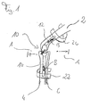
- the device shown in Fig. 1 is for post-operative treatment in the event of injury of the anterior cruciate ligament.
- This device comprises two joints 10, one of which 1, however, only one is shown, as well as two coupling elements 20 and 22.
- the joints 10 are arranged medially and laterally and via the coupling elements 20 and 22 connected together.
- Each of the joints 10 comprises two in the form of joint rails 12 and 14 formed stabilizing elements, of which the hinge rail 12th runs approximately parallel to the femur 2, while the joint splint 14 approximately runs parallel to the lower leg bones (tibia 4 and fibula 6).
- the coupling element 14 runs dorsally around the thigh, while the joint splint 16 the lower leg bones circulates ventrally.
- FIG Movements represented by the symbols A after treatment of injuries of the anterior cruciate ligament 8 can be prevented.
- the device can be connected to the respective Operating conditions are adapted by the coupling elements 20 and 22nd moved along the joint rails 12 and 14 and locked in the desired position are, as shown by the double arrows B in Fig. 1.
- the embodiment of the invention shown in FIG. 2 has in addition to the on the basis of the 1 already explained elements also a compression device designated overall by 30 on, which is releasably attached to the articulated rails 12 and 14. To can be surface fasteners or pockets provided in the compression device can be used to accommodate the joint rails.
- the compression device has a bandage body 32 and a gel insert designated 40 in total on the knee joint in the area of the kneecap.
- the bandage body 32 rotates the parts of the thigh and lower leg adjacent to the knee joint and can be provided with surface fasteners 34 or 36 can be set.
- the gel insert shown in Fig. 3 includes a gel pad 42 and a textile strip 44 holding the gel cushion 42. In the area of the upper and lower Surface adhesive fasteners 46 are provided on the edge of the textile strip 44, with which the Gel insert on the bandage body 32 can be fixed.
- FIG. 2 they are made of a thermoplastic Plastic coupling elements 20 and 22 anatomically shaped and have a flat contact surface for the limbs adjacent to the knee joint on.
- the embodiment shown in the drawing has a modular structure overall, so that the joints 10, coupling elements 20 and 22 and the compression device 30 are releasably connected. Therefore, all individual parts of the in Fig. 2nd device shown to be adapted to the respective operating conditions become.
- the compression device 30 is also modular built up so that the gel insert and the bandage body are exchanged depending on the application can be.
- Fig. 4 shows schematically one way of realizing the displaceability of the Coupling elements 20 and 22 along the articulated rails 12 and 14, respectively, which in FIGS. 1 and 2 is indicated by the double arrows B.
- the elongated holes are generally designated by the reference number 52.
- a snap button 54 is provided on the articulated rail 12, which has mushroom-shaped structure. The trunk of the snap button 54 fits through Elongated holes 52, both in the narrow section 48 and in the wide Section 50.
- the head of the snap button 54 only fits through the wide section 50, but not through the narrow section 48 of the elongated holes 52 Condition are the coupling elements 20 and 22 along the hinge rails 12 or 14 slidably by the snap button 54 along the narrow portion 48 of the Slot 52 is moved.
- the snap button 54 can be designed as a screw, which is screwed into a corresponding thread in the joint rail 12 or 14, whereby a locking of the coupling element 20 or 22 in the desired relative position to the joint rail 12 or 14 is possible because the underside of the head of the A button of a region of the coupling element 20 surrounding the elongated hole 52 or 22 clamps.
- the embodiment shown in FIGS. 1 to 4 can the invention, for example, for the postoperative treatment of injuries to the anterior cruciate ligament.
- the The invention is also not limited to the knee orthoses shown in the drawing. Rather, the basic idea of the modular structure and the variable attachment of individual Device elements also for therapies and prophylaxis for other joints, such as ankles, because the basic idea of the modular structure is the Therapy principles of all ligament injuries of the joints are taken into account. To do this, the Product can only be adapted to the anatomical requirements.
Abstract
Die Erfindung betrifft eine Vorrichtung zur medizinischen Versorgung und Prophylaxe von Gelenkverletzungen, mit mindestens einem mindestens zwei gelenkig miteinander verbundene Stabilisierungselemente (12,14) aufweisenden Gelenk (10) und mindestens einem an mindestens einem der Stabilisierungselemente befestigten und an das zu versorgende Gelenk angrenzendes Körperglied zumindest teilweise umlaufenden, vorzugsweise starren Kopplungselement (20,22), wobei die Lage des Kopplungselementes bezüglich der Gelenkachse einstellbar ist.The invention relates to a device for medical care and prophylaxis of joint injuries, with at least one joint (10) having at least two stabilizing elements (12, 14) connected to one another and at least one limb attached to at least one of the stabilizing elements and adjacent to the joint to be treated partially circumferential, preferably rigid coupling element (20, 22), the position of the coupling element with respect to the joint axis being adjustable.
Description
Die Erfindung betrifft eine Vorrichtung zur medizinischen Versorgung von Gelenkverletzungen, mit mindestens einem mindestens zwei gelenkig miteinander verbundene Stabilisierungselemente aufweisenden Gelenk und mindestens einem an mindestens einem der Stabilisierungselemente befestigten und ein an das zu versorgende Gelenk angrenzendes Körperglied zumindest teilweise umlaufenden, vorzugsweise starren Kopplungselement.The invention relates to a device for the medical care of joint injuries, with at least one at least two stabilizing elements articulated to one another having joint and at least one on at least one of the Stabilizing elements attached and an adjacent to the joint to be supplied Body member at least partially encircling, preferably rigid coupling element.
Derartige Vorrichtungen werden beispielsweise in Form von sog. Orthesen zur medizinischen Versorgung von Knieverletzungen eingesetzt. Dabei können diese Knieorthesen in der präoperativen und postoperativen Phase sowie in der Rehabilitation und Prophylaxe verwendet werden. Beim Einsatz der bekannten Knieorthesen dienen die gelenkig miteinander verbundenen Stabilisierungselemente zur Rotationsstabilisierung der über das mindestens eine Kopplungselement daran gekoppelten, an das zu versorgende Gelenk angrenzenden Körperglieder bei Beanspruchungen des zu versorgenden Gelenkes. Zu diesem Zweck ist den Stabilisierungselementen bekannter Knieorthesen üblicherweise eine Begrenzungseinrichtung zugeordnet, mit der die Schwenkbewegung des einen Stabilisierungselementes bezüglich dem anderen Stabilisierungselement um die Gelenkachse begrenzt werden kann. Zusammenwirkend mit dem Kopplungselement kann so eine Begrenzung der Flexion und Extension des zu versorgenden Gelenkes erreicht werden.Such devices are used, for example, in the form of so-called orthoses for medical purposes Treatment of knee injuries used. These knee braces can be used in the preoperative and postoperative phase as well as in rehabilitation and prophylaxis be used. When using the known knee orthoses, they are articulated with one another connected stabilizing elements for rotational stabilization of the at least one coupling element coupled thereto, adjacent to the joint to be supplied Limbs of the body when the joint to be supplied is stressed. To this The purpose of the stabilizing elements of known knee orthoses is usually one Assigned limiting device with which the pivoting movement of the one stabilizing element with respect to the other stabilizing element about the hinge axis can be limited. In cooperation with the coupling element, there can be a limitation the flexion and extension of the joint to be treated can be achieved.
Bei handelsüblichen Orthesen wird durch Bereitstellung von zwei jeweils zweigelenkig miteinander verbundene Stabilisierungselemente aufweisenden Gelenken an jeweils einer Seite des zu versorgenden Gelenkes (beispielsweise lateral und medial) eine besonders gute Stabilisierung erreicht, wobei die Stabilisierungselemente der beidseits des zu versorgenden Gelenkes angeordneten Gelenke der Vorrichtung üblicherweise über mindestens ein Kopplungselement miteinander verbunden sind. Dabei weisen handelsübliche Orthesen mindestens zwei Kopplungselemente auf, von denen jedes an einem der Stabilisierungselemente befestigt ist, wobei die Kopplungselemente die an das zu versorgende Gelenk angrenzenden Körperglieder auf einander entgegengesetzten Seiten, beispielsweise dorsal und ventral, umlaufen.In the case of commercially available orthoses, two are provided with two joints each interconnected stabilizing elements having joints on one One side of the joint to be treated (for example laterally and medially) good stabilization achieved, the stabilizing elements on both sides of the supply Articulated joints of the device usually over at least a coupling element are connected to each other. Standard orthoses show at least two coupling elements, each on one of the stabilizing elements is attached, wherein the coupling elements to the joint to be supplied adjacent limbs on opposite sides, for example dorsally and ventrally, circulate.
Trotz dieser aufwendigen Stabilisierungsmaßnahmen kann es beim Einsatz herkömmlicher Vorrichtungen der eingangs beschriebenen Art noch zu unerwünschten oder schädlichen Beanspruchungen des zu versorgenden Gelenkes kommen.Despite these complex stabilization measures, it can be used more traditionally Devices of the type described above are still undesirable or harmful Stresses on the joint to be supplied come.
Angesichts dieser Probleme im Stand der Technik liegt der Erfindung die Aufgabe zugrunde, eine Vorrichtung zur medizinischen Versorgung von Gelenkverletzungen bereitzustellen, mit der unerwünschte Belastungen des zu versorgenden Gelenkes zuverlässig verhindert werden können.In view of these problems in the prior art, the invention is based on the object to provide a device for medical care of joint injuries, with the undesirable loads of the joint to be supplied reliably can be prevented.
Erfindungsgemäß wird diese Aufgabe durch eine Weiterbildung der bekannten Vorrichtungen gelöst, die im wesentlichen dadurch gekennzeichnet ist, daß die Lage des Kopplungselementes bezüglich der Gelenkachse einstellbar ist.According to the invention, this object is achieved by developing the known devices solved, which is essentially characterized in that the location of the Coupling element is adjustable with respect to the hinge axis.
Diese Erfindung geht auf die Erkenntnis zurück, daß die im Stand der Technik beobachteten Probleme in erster Linie auf die in einigen Fällen mangelhafte Ankopplung der an das zu versorgende Gelenk angrenzenden Körperglieder an die Stabilisierungselemente zurückzuführen sind. Diese mangelhafte Ankopplung hat wiederum zur Folge, daß es noch zu unkontrollierten Bewegungen dieser Körperglieder kommen kann, welche eine unerwünschte Beanspruchung des zu versorgenden Gelenkes verursachen können. Durch die erfindungsgemäße Weiterbildung der bekannten Vorrichtungen kann diese mangelhafte Ankopplung verbessert werden, weil durch die Einstellung der Lage des Kopplungselementes bezüglich der Gelenkachse eine individuelle Anpassung der Vorrichtung an den Körperbau des zu behandelnden Patienten vorgenommen werden kann. Diese Anpassung ermöglicht eine besonders wirkungsvolle Ankopplung der Bewegung der an das zu versorgende Gelenk angrenzenden Körperglieder an die Stabilisierungselemente und mithin eine zuverlässige Vermeidung unerwünschter Belastungen des zu versorgenden Gelenkes.This invention is based on the knowledge that those observed in the prior art Problems primarily due to the poor coupling in some cases the joint to be supplied adjacent limbs to the stabilizing elements are due. This inadequate coupling in turn means that it is still uncontrolled movements of these limbs can occur, which is an undesirable Can cause stress on the joint to be supplied. Through the Further development of the known devices according to the invention can be defective Coupling can be improved because of the adjustment of the position of the coupling element an individual adaptation of the device to the Physique of the patient to be treated can be made. This adjustment enables a particularly effective coupling of the movement of the to be supplied Joint adjacent limbs to the stabilizing elements and therefore one reliable avoidance of undesirable loads on the joint to be supplied.
Wie im Zusammenhang mit aus dem Stand der Technik bekannten Vorrichtungen bereits erläutert, hat es sich im Sinn einer besonders wirkungsvollen Ankopplung der Körperglieder an die erfindungsgemäße Vorrichtung als besonders günstig erwiesen, wenn mindestens zwei Kopplungselemente vorgesehen sind, von denen jedes an einem der Stabilisierungselemente des Gelenkes der Vorrichtung befestigt ist. Diese Ankopplung kann weiter verbessert werden, wenn die Kopplungselemente die an das zu versorgende Gelenk angrenzenden Körperglieder auf einander entgegengesetzten Seiten umlaufen. Bei Einsatz einer erfindungsgemäßen Vorrichtung in Form einer Knieorthese hat es sich als besonders günstig erwiesen, wenn eines der Kopplungselemente den Oberschenkelknochen dorsal umläuft, während ein anderes Kopplungselement die Unterschenkelknochen (Tibia und Fibula) ventral umläuft.As in connection with devices known from the prior art explained, it has been in the sense of a particularly effective coupling of the limbs to the device according to the invention proved to be particularly favorable if at least two coupling elements are provided, each on one of the stabilizing elements the hinge of the device is attached. This coupling can can be further improved if the coupling elements are connected to the joint to be supplied circumscribe adjacent limbs on opposite sides. When in use a device according to the invention in the form of a knee orthosis has been found to be special Conveniently proven if one of the coupling elements dorsally the femur orbits the lower leg bones (tibia and Fibula) revolves ventrally.
Wenngleich die Einstellung der Lage der Kopplungselemente bezüglich der Gelenkachse auch dann vorgenommen werden kann, wenn die Kopplungselemente unverlierbar an den Stabilisierungselementen befestigt sind und die Einstellung durch eine Verschiebung der Kopplungselemente längs den Stabilisierungselementen in einer senkrecht zur Gelenkachse verlaufenden Richtung vorgenommen wird, hat es sich im Hinblick auf den Erhalt einer besonders guten Anpassung der erfindungsgemäßen Vorrichtung an die jeweiligen Einsatzbedingungen als besonders vorteilhaft erwiesen, wenn mindestens ein Kopplungselement lösbar mit dem mindestens einen Stabilisierungselement verbunden ist. In diesem Fall kann nicht nur die Lage des Kopplungselementes bezüglich des Stabilisierungselementes zur Anpassung an die jeweiligen Einsatzbedingungen eingestellt werden, sondern auch ein Austausch von Kopplungselementen vorgenommen werden. Das kann beispielsweise dann erforderlich werden, wenn die Form des Kopplungselementes keine zufriedenstellende Ankopplung an das entsprechende Körperglied ermöglicht und aus diesem Grund ein anders geformtes Kopplungselement benutzt werden muß.Although the adjustment of the position of the coupling elements with respect to the axis of the joint can also be made if the coupling elements are captive are attached to the stabilizing elements and adjustment by displacement of the coupling elements along the stabilizing elements in a perpendicular to Joint axis extending direction is made, it has with regard to the Obtaining a particularly good adaptation of the device according to the invention to the respective Operating conditions proved to be particularly advantageous if at least one coupling element is detachably connected to the at least one stabilizing element. In in this case, not only the position of the coupling element with respect to the stabilizing element be adjusted to adapt to the respective operating conditions, but also an exchange of coupling elements can be made. That can for example, be required if the shape of the coupling element is none allows satisfactory coupling to and from the corresponding limb Because a differently shaped coupling element must be used.
Wie eingangs bereits im Zusammenhang mit herkömmlichen Vorrichtungen zur medizinischen Versorgung von Gelenkverletzungen erläutert, hat es sich im Hinblick auf den Erhalt einer besonders zuverlässigen Stabilisierung des zu versorgenden Gelenkes als zweckmäßig erwiesen, wenn zwei koaxial zueinander verlaufende Gelenkachsen aufweisende Gelenke vorgesehen sind. Beim Einsatz einer erfindungsgemäßen Vorrichtung in Form einer Knieorthese kann eines dieser Gelenke medial angeordnet sein, während das andere lateral angeordnet ist. Dabei können diese Gelenke über mindestens ein, vorzugsweise zwei beidseits der Gelenkachse angeordnete Kopplungselemente miteinander verbunden sein, wobei diese Verbindung in besonders vorteilhafter Ausgestaltung der Erfindung jeweils lösbar ausgeführt ist. Auch bei den erfindungsgemäßen Vorrichtungen kann mindestens einem der Gelenke eine Begrenzungseinrichtung zugeordnet sein, mit der eine Schwenkbewegung des einen Stabilisierungselementes bezüglich dem anderen Stabilisierungselement um die Gelenkachse begrenzt wird, um so eine Begrenzung von Flexion und Extension der über die Kopplungselemente an die Gelenke gekoppelten Körperglieder zu erreichen.As already mentioned in connection with conventional devices for medical Care for joint injuries has been explained with regard to Obtaining a particularly reliable stabilization of the joint to be supplied as Proven useful if two coaxial joint axes Joints are provided. When using a device according to the invention in In the form of a knee orthosis, one of these joints can be arranged medially, while the another is arranged laterally. These joints can have at least one, preferably two coupling elements arranged on both sides of the joint axis are connected to one another be, this connection in a particularly advantageous embodiment of the invention is designed to be detachable. Can also with the devices according to the invention At least one of the joints can be assigned a limiting device with which one Pivotal movement of one stabilizing element with respect to the other stabilizing element is limited around the axis of the joint so as to limit flexion and Extension of the limbs coupled to the joints via the coupling elements to reach.
Zusätzlich zu den bislang erläuterten Elementen kann eine erfindungsgemäße Vorrichtung auch noch weitere funktionale Elemente, wie etwa eine das zu versorgende Gelenk und/oder mindestens ein an das zu versorgende Gelenk angrenzendes Körperglied umlaufende, vorzugsweise lösbar mit einem der Stabilisierungselemente und/oder dem mindestens einen Kopplungselement verbundene Kompressionseinrichtung, aufweisen. Eine beispielsweise in Form eines Bandagenelementes vorliegende Kompressionseinrichtung kann eingesetzt werden, um Schwellungen entgegenzuwirken und/oder eine Stimulanz der Sensomotorik im Bereich des zu versorgenden Gelenkes herbeizuführen. Im Sinne einer besonders günstigen Anpassung an die jeweiligen Einsatzbedingungen kann die Kompressionseinrichtung zwei oder mehr vorzugsweise lösbar miteinander verbundene Kompressionselemente aufweisen. Dabei kann die lösbare Verbindung in besonders vorteilhafter Ausgestaltung der Erfindung mit Hilfe von Flächenhaftverschlüssen hergestellt werden. Bei einer insbesondere für die Versorgung von Knieverletzungen einsetzbaren Vorrichtung weist die Kompressionseinrichtung neben einem Bandagenkörper auch noch mindestens einen Geleinsatz auf, welcher sich besonders gut an die jeweilige Gelenkform anpaßt. Mit einem derartigen Geleinsatz kann beispielsweise die Patella stabilisiert und einer Patellalateralisation entgegengewirkt werden.In addition to the elements explained so far, a device according to the invention can also other functional elements, such as a joint to be supplied and / or at least one limb adjacent to the joint to be treated circumferential, preferably detachable with one of the stabilizing elements and / or the have at least one coupling element connected compression device. A compression device, for example in the form of a bandage element can be used to counteract swelling and / or stimulation the sensorimotor system in the area of the joint to be supplied. For the purpose of a particularly favorable adaptation to the respective operating conditions can Compression device two or more, preferably detachably connected to each other Have compression elements. The detachable connection can be particularly advantageous Embodiment of the invention made using surface fasteners become. When used in particular for the care of knee injuries The compression device also has a device in addition to a bandage body at least one gel insert, which adapts particularly well to the respective joint shape adapts. With such a gel insert, for example, the patella can be stabilized and counteracting patellar lateralization.
Der Bandagenkörper einer erfindungsgemäßen Vorrichtung kann beispielsweise in Form eines Textillaminates vorliegen.The bandage body of a device according to the invention can, for example, in Form of a textile laminate.
Gemäß einem weiteren Gesichtspunkt der Erfindung kann eine besonders gute Anpassung einer erfindungsgemäßen Vorrichtung mit mindestens einem mindestens zwei gelenkig miteinander verbundene Stabilisierungselemente aufweisenden Gelenk, mindestens einem mit mindestens einem Stabilisierungselement verbundenen Kopplungselement und mindestens einer mit dem Gelenk und/oder dem Kopplungselement verbundenen Kompressionseinrichtung an die jeweilige Benutzungsbedingungen erreicht werden, wenn alle Verbindungen zwischen dem Stabilisierungselement, dem Kopplungselement und der Kompressionseinrichtung lösbar sind, weil durch die so erreichte Modularität der Gesamtvorrichtung sämtliche Elemente zum Erhalt einer idealen Anpassung an die jeweiligen Einsatzbedingungen ausgetauscht werden können. Im Sinne einer besonders einfachen Anpassung an die jeweiligen Einsatzbedingungen hat es sich als besonders günstig erwiesen, wenn mindestens ein Kopplungselement zumindest teilweise aus thermoplastischem Kunststoff besteht. Zusätzlich oder teilweise kann das Kopplungselement aber auch Teile aus faserverstärktem Kunststoff aufweisen, um so eine besonders hohe Stabilität zu erhalten. Das Stabilisierungselement der erfindungsgemäßen Vorrichtung kann aus Aluminium, Carbon und/oder Glasfasern bestehen. Dabei können die Stabilisierungselemente der erfindungsgemäßen Vorrichtung in besonders vorteilhafter Ausgestaltung anatomisch vorgeformt sein.According to a further aspect of the invention, particularly good adaptation can be achieved a device according to the invention with at least one at least two articulated joint having stabilizing elements, at least a coupling element connected to at least one stabilizing element and at least one connected to the joint and / or the coupling element Compression device to the respective conditions of use can be achieved if all connections between the stabilizing element, the coupling element and the Compression device can be solved because of the modularity of the overall device achieved in this way all elements to obtain an ideal adaptation to the respective operating conditions can be exchanged. In the sense of a particularly simple adjustment it has proven to be particularly favorable to the respective operating conditions, if at least one coupling element is at least partially made of thermoplastic Plastic is made. Additionally or partially, the coupling element can also be parts have made of fiber-reinforced plastic in order to obtain a particularly high stability. The stabilizing element of the device according to the invention can be made of aluminum, Carbon and / or glass fibers exist. The stabilizing elements can Device according to the invention anatomically preformed in a particularly advantageous embodiment his.
Nachstehend wird die Erfindung unter Bezugnahme auf die Zeichnung, auf die hinsichtlich aller erfindungswesentlichen und in der Beschreibung nicht besonders hervorgehobenen Einzelheiten verwiesen wird, erläutert. In der Zeichnung zeigt:
- Fig. 1
- eine schematische Seitenansicht einer erfindungsgemäßen Vorrichtung,
- Fig. 2
- eine erfindungsgemäße Knieorthese mit modularem Aufbau,
- Fig. 3
- einen Geleinsatz für die Knieorthese nach Fig. 1 und
- Fig. 4
- schematisch ein Detail der Vorrichtung nach Fig. 1.
- Fig. 1
- 2 shows a schematic side view of a device according to the invention,
- Fig. 2
- a knee orthosis according to the invention with a modular structure,
- Fig. 3
- a gel insert for the knee brace according to Fig. 1 and
- Fig. 4
- schematically shows a detail of the device of FIG. 1st
Die in Fig. 1 dargestellte Vorrichtung ist zur postoperativen Behandlung bei Verletzung
des vorderen Kreuzbandes gedacht. Diese Vorrichtung umfaßt zwei Gelenke 10, von denen
in Fig. 1 jedoch nur eines dargestellt ist, sowie zwei Kopplungselemente 20 und 22.
Die Gelenke 10 sind medial und lateral angeordnet und über die Kopplungselemente 20
und 22 miteinander verbunden. Jedes der Gelenke 10 umfaßt zwei in Form von Gelenkschienen
12 und 14 gebildete Stabilisierungselemente, von denen die Gelenkschiene 12
etwa parallel zum Oberschenkelknochen 2 verläuft, während die Gelenkschiene 14 etwa
parallel zu den Unterschenkelknochen (Tibia 4 und Fibula 6) verläuft. Das Kopplungselement
14 umläuft den Oberschenkel dorsal, während die Gelenkschiene 16 die Unterschenkelknochen
ventral umläuft. Mit der in Fig. 1 dargestellten Anordnung können die in Fig. 1
durch die Symbole A dargestellten Bewegungen nach Behandlungen von Verletzungen
des vorderen Kreuzbandes 8 verhindert werden. Dabei kann die Vorrichtung an die jeweiligen
Einsatzbedingungen angepaßt werden, indem die Kopplungselemente 20 und 22
längs den Gelenkschienen 12 bzw. 14 verschoben und in der gewünschten Stellung arretiert
werden, wie durch die Doppelpfeile B in Fig. 1 dargestellt.The device shown in Fig. 1 is for post-operative treatment in the event of injury
of the anterior cruciate ligament. This device comprises two
Die in Fig. 2 dargestellte Ausführungsform der Erfindung weist neben den anhand der
Fig. 1 bereits erläuterten Elemente auch noch eine insgesamt mit 30 bezeichnete Kompressionseinrichtung
auf, die lösbar an den Gelenkschienen 12 und 14 befestigt ist. Dazu
können Flächenhaftverschlüsse oder in der Kompressionseinrichtung vorgesehene Taschen
zur Aufnahme der Gelenkschienen eingesetzt werden. Die Kompressionseinrichtung
weist einen Bandagenkörper 32 sowie einen insgesamt mit 40 bezeichneten Geleinsatz
auf, der im Bereich der Kniescheibe am Kniegelenk anliegt. Der Bandagenkörper 32 umläuft
die an das Kniegelenk angrenzenden Teile des Oberschenkels und Unterschenkels
und kann mit Hilfe von an seinen Rändern vorgesehenen Flächenhaftverschlüssen 34 bzw.
36 festgelegt werden. Der in Fig. 3 dargestellte Geleinsatz umfaßt ein Gelkissen 42 sowie
einen das Gelkissen 42 haltenden Textilstreifen 44. Im Bereich des oberen und unteren
Randes des Textilstreifens 44 sind Flächenhaftverschlüsse 46 vorgesehen, mit denen der
Geleinsatz am Bandagenkörper 32 festgelegt werden kann.The embodiment of the invention shown in FIG. 2 has in addition to the on the basis of the
1 already explained elements also a compression device designated overall by 30
on, which is releasably attached to the articulated
Wie in Fig. 2 besonders deutlich zu erkennen ist, sind die aus einem thermoplastischen
Kunststoff hergestellten Kupplungselemente 20 und 22 anatomisch geformt und
weisen eine flächige Anlagefläche für die an das Kniegelenk angrenzenden Körperglieder
auf. Die in der Zeichnung dargestellte Ausführungsform ist insgesamt modular aufgebaut,
so daß die Gelenke 10, Kupplungselemente 20 und 22 sowie die Kompressionseinrichtung
30 lösbar miteinander verbunden sind. Daher können sämtliche Einzelteile der in Fig. 2
dargestellten Vorrichtung zur Anpassung an die jeweiligen Einsatzbedingungen ausgetauscht
werden. Darüber hinaus ist auch noch die Kompressionseinrichtung 30 modular
aufgebaut, so daß der Geleinsatz und der Bandagenkörper je nach Einsatzgebiet ausgetauscht
werden können.As can be seen particularly clearly in FIG. 2, they are made of a thermoplastic
Fig. 4 zeigt schematisch eine Möglichkeit der Realisierung der Verschiebbarkeit der
Kopplungselemente 20 und 22 längs der Gelenkschienen 12 bzw. 14, die in den Fig. 1 und
2 durch die Doppelpfeile B angedeutet ist. Dazu sind Langlöcher, beispielsweise an dem
Kopplungselement 20, vorgesehen, die einen schmaleren Abschnitt 48 und einen weiteren
Abschnitt 50 aufweisen. Die Langlöcher sind insgesamt mit der Bezugszahl 52 bezeichnet.
Beispielsweise an der Gelenkschiene 12 ist passend dazu ein Einrastknopf 54 vorgesehen,
der pilzförmige Struktur hat. Dabei paßt der Stamm des Einrastknopfes 54 durch die
Langlöcher 52, und zwar sowohl in dem schmalen Abschnitt 48 als auch in dem weiten
Abschnitt 50. Der Kopf des Einrastknopfes 54 paßt hingegen nur durch den weiten Abschnitt
50, nicht aber durch den schmalen Abschnitt 48 der Langlöcher 52. In angebrachtem
Zustand sind dadurch die Kopplungselemente 20 und 22 längs den Gelenkschienen
12 bzw. 14 verschieblich, indem der Einrastknopf 54 längs dem schmalen Abschnitt 48 des
Langlochs 52 verschoben wird. Der Einrastknopf 54 kann als Schraube ausgestaltet sein,
die in ein entsprechendes Gewinde in der Gelenkschiene 12 bzw. 14 eingeschraubt wird,
wodurch eine Arretierung des Kopplungselementes 20 bzw. 22 in der gewünschten Relativstellung
zu der Gelenkschiene 12 bzw. 14 möglich ist, weil die Unterseite des Kopfes des
Einrastknopfes einen das Langloch 52 umgebenden Bereich des Kopplungselementes 20
bzw. 22 festklemmt.Fig. 4 shows schematically one way of realizing the displaceability of the
Wie vorstehend erläutert, kann die anhand der Fig. 1 bis 4 dargestellte Ausführungsform der Erfindung beispielsweise zur postoperativen Behandlung von Verletzungen des vorderen Kreuzbandes eingesetzt werden. Daneben können Vorrichtungen der in den Fig. 1 bis 4 dargestellten Art aber auch zur posttraumatischen und postoperativen Versorgung anderer Knieverletzungen, im Rahmen der Rehabilitation sowie zur Rezidivprophylaxe eingesetzt werden, was nur durch den modularen Aufbau ermöglicht wird. Im übrigen ist die Erfindung auch nicht auf die in der Zeichnung dargestellten Knieorthesen beschränkt. Vielmehr kann die Grundidee des modularen Aufbaus und der variablen Anbringung einzelner Vorrichtungselemente auch für Therapien und Prophylaxen bei anderen Gelenken, wie etwa Fußgelenken, eingesetzt werden, weil die Grundidee des modularen Aufbaus die Therapieprinzipien aller Ligamentverletzungen der Gelenke berücksichtigt. Dazu muß das Produkt lediglich den anatomischen Erfordernissen angepaßt werden.As explained above, the embodiment shown in FIGS. 1 to 4 can the invention, for example, for the postoperative treatment of injuries to the anterior cruciate ligament. In addition, devices of the type shown in FIGS. 1 to 4 shown type but also for post-traumatic and post-operative care other knee injuries, used in the context of rehabilitation and for relapse prevention what is only made possible by the modular structure. Otherwise, the The invention is also not limited to the knee orthoses shown in the drawing. Rather, the basic idea of the modular structure and the variable attachment of individual Device elements also for therapies and prophylaxis for other joints, such as ankles, because the basic idea of the modular structure is the Therapy principles of all ligament injuries of the joints are taken into account. To do this, the Product can only be adapted to the anatomical requirements.
Claims (13)
Applications Claiming Priority (2)
| Application Number | Priority Date | Filing Date | Title |
|---|---|---|---|
| DE2000157462 DE10057462A1 (en) | 2000-11-20 | 2000-11-20 | Orthosis, in particular to be used after knee operation, comprising adjustable fastening elements |
| DE10057462 | 2000-11-20 |
Publications (2)
| Publication Number | Publication Date |
|---|---|
| EP1208822A2 true EP1208822A2 (en) | 2002-05-29 |
| EP1208822A3 EP1208822A3 (en) | 2002-06-05 |
Family
ID=7663930
Family Applications (1)
| Application Number | Title | Priority Date | Filing Date |
|---|---|---|---|
| EP01127583A Withdrawn EP1208822A3 (en) | 2000-11-20 | 2001-11-19 | Apparatus for medical treatment of injured joint |
Country Status (3)
| Country | Link |
|---|---|
| EP (1) | EP1208822A3 (en) |
| DE (1) | DE10057462A1 (en) |
| ES (1) | ES2176132T1 (en) |
Cited By (2)
| Publication number | Priority date | Publication date | Assignee | Title |
|---|---|---|---|---|
| US9125787B2 (en) | 2011-09-30 | 2015-09-08 | Covidien Lp | Compression garment having a foam layer |
| US9402779B2 (en) | 2013-03-11 | 2016-08-02 | Covidien Lp | Compression garment with perspiration relief |
Families Citing this family (1)
| Publication number | Priority date | Publication date | Assignee | Title |
|---|---|---|---|---|
| DE102009027730A1 (en) | 2009-07-15 | 2011-01-27 | Evonik Degussa Gmbh | Procedure and use of amino-functional resins for dismutation of halosilanes and for removal of foreign metals |
Citations (7)
| Publication number | Priority date | Publication date | Assignee | Title |
|---|---|---|---|---|
| FR2593391A1 (en) * | 1986-01-30 | 1987-07-31 | Valat Eric | Knee-protection device |
| US4982732A (en) * | 1990-02-06 | 1991-01-08 | Orthopedic Technology, Inc. | Orthopedic rehabilitation knee brace |
| US5154690A (en) * | 1990-03-05 | 1992-10-13 | Tokyo Eizai Laboratory Company, Ltd. | Supporter |
| US5277697A (en) * | 1990-08-17 | 1994-01-11 | Hanger Orthopedic Group, Inc. | Patella-femoral brace |
| DE4418806A1 (en) * | 1994-05-30 | 1995-12-14 | Bock Orthopaed Ind | Knee brace |
| US5797864A (en) * | 1996-11-14 | 1998-08-25 | Generation Ii Orthotics, Inc. | Multi-purpose brace |
| US5817040A (en) * | 1995-08-24 | 1998-10-06 | Restorative Care Of America Incorporated | Knee and elbow orthosis |
Family Cites Families (8)
| Publication number | Priority date | Publication date | Assignee | Title |
|---|---|---|---|---|
| US4938207A (en) * | 1986-10-20 | 1990-07-03 | Alexander C. Vargo | Knee brace having plurality of fluid filled chambers surrounding knee |
| US5018514A (en) * | 1987-06-11 | 1991-05-28 | Brace Technologies, Inc. | Knee brace |
| US5025782A (en) * | 1990-02-12 | 1991-06-25 | Ambulatory Traction Inc. | Adjustable rack and pinion knee brace |
| US5063916A (en) * | 1990-06-01 | 1991-11-12 | Minnesota Mining And Manufacturing Company | Knee brace having freecentric locking hinge |
| DE4140554A1 (en) * | 1991-12-09 | 1993-06-17 | Biedermann Motech Gmbh | KNEE ORTHESIS |
| EP0809478B1 (en) * | 1995-02-15 | 2002-05-29 | dj Orthopedics, LLC | Knee brace having an inflatable pad circumscribing the patella |
| US5891071A (en) * | 1995-12-07 | 1999-04-06 | Lenox Hill, A Division Fo Dobi-Symplex | Leg brace |
| DE19605734C2 (en) * | 1996-02-16 | 2000-01-20 | Beiersdorf Ag | Knee joint orthosis with different lateral and medial orthotic joint |
-
2000
- 2000-11-20 DE DE2000157462 patent/DE10057462A1/en not_active Withdrawn
-
2001
- 2001-11-19 ES ES01127583T patent/ES2176132T1/en active Pending
- 2001-11-19 EP EP01127583A patent/EP1208822A3/en not_active Withdrawn
Patent Citations (7)
| Publication number | Priority date | Publication date | Assignee | Title |
|---|---|---|---|---|
| FR2593391A1 (en) * | 1986-01-30 | 1987-07-31 | Valat Eric | Knee-protection device |
| US4982732A (en) * | 1990-02-06 | 1991-01-08 | Orthopedic Technology, Inc. | Orthopedic rehabilitation knee brace |
| US5154690A (en) * | 1990-03-05 | 1992-10-13 | Tokyo Eizai Laboratory Company, Ltd. | Supporter |
| US5277697A (en) * | 1990-08-17 | 1994-01-11 | Hanger Orthopedic Group, Inc. | Patella-femoral brace |
| DE4418806A1 (en) * | 1994-05-30 | 1995-12-14 | Bock Orthopaed Ind | Knee brace |
| US5817040A (en) * | 1995-08-24 | 1998-10-06 | Restorative Care Of America Incorporated | Knee and elbow orthosis |
| US5797864A (en) * | 1996-11-14 | 1998-08-25 | Generation Ii Orthotics, Inc. | Multi-purpose brace |
Non-Patent Citations (2)
| Title |
|---|
| JOHN H ET AL: "DER EINSATZ VON KNIEORTHESEN AUS ORTHOPAEDIETECHNISCHER SICHT USE OF KNEE-BRACES IN TECHNICAL RESPECT" MEDIZINISCH ORTHOPADISCHE TECHNIK, GENTNER VERLAG. STUTTGART, DE, Bd. 115, Nr. 1, 1995, Seiten 33-36, XP000489727 ISSN: 0340-5508 * |
| RIEDER TH ET AL: "DIE LANGE KNIEORTHESE - WEITERENTWICKLUNG AUF DER BASIS BEWAHRTER PRINZIPIEN" MEDIZINISCH ORTHOPADISCHE TECHNIK, GENTNER VERLAG. STUTTGART, DE, Bd. 109, Nr. 5, 1. September 1989 (1989-09-01), Seiten 189-190,192-193, XP000084496 ISSN: 0340-5508 * |
Cited By (2)
| Publication number | Priority date | Publication date | Assignee | Title |
|---|---|---|---|---|
| US9125787B2 (en) | 2011-09-30 | 2015-09-08 | Covidien Lp | Compression garment having a foam layer |
| US9402779B2 (en) | 2013-03-11 | 2016-08-02 | Covidien Lp | Compression garment with perspiration relief |
Also Published As
| Publication number | Publication date |
|---|---|
| EP1208822A3 (en) | 2002-06-05 |
| DE10057462A1 (en) | 2002-05-23 |
| ES2176132T1 (en) | 2002-12-01 |
Similar Documents
| Publication | Publication Date | Title |
|---|---|---|
| DE69913179T2 (en) | Knee brace equipped with sagittal regulation | |
| EP0164374B1 (en) | Orthopedic device for the knee joint | |
| EP0627205B1 (en) | Ankle brace | |
| DE60129962T2 (en) | Body support device | |
| DE112012004113B4 (en) | Orthosis for the correction of upper arm fractures | |
| DE102009038517B4 (en) | Modular system for assembling an orthosis for a knee and method for converting an orthosis from this modular system | |
| DE2528583B2 (en) | Device for the surgical treatment of bones and joints | |
| EP1588678A1 (en) | Modular hip orthosis | |
| EP1179325A1 (en) | Ankle joint bandage | |
| EP0917864A2 (en) | Minimal orthesis for the treatment of osteoporosis | |
| DE60205192T2 (en) | Joint splint for controlling and regulating the flexion of the knee joint | |
| EP3713526A1 (en) | Limb orthosis, in particular knee brace | |
| DE4013693C2 (en) | ||
| DE102006011465A1 (en) | Knees weight relieving device for treating arthrosis, has supports connecting upper and lower sealing units, where upper unit sits below small protuberance in thigh, which is arranged in area of buttock muscle or gluteus maximus muscle | |
| EP0832623B1 (en) | Spreader orthosis | |
| EP1208822A2 (en) | Apparatus for medical treatment of injured joint | |
| DE202007012383U1 (en) | Saw jig for performing a bone resection | |
| EP0067319A2 (en) | Knee splint | |
| EP0751754B1 (en) | Knee orthesis | |
| CH596826A5 (en) | Surgical braces for fractured bones | |
| DE2714272C3 (en) | Spreader for the treatment of hip dysplasia | |
| AT402687B (en) | SWIVELABLE CONNECTING SWIVELING KNEE GUIDE RAILS | |
| DE3340021A1 (en) | Joint manipulator | |
| DE202005010491U1 (en) | Foot orthotic has front blade with strap to big toe and rear blade with strap to foot arch | |
| EP3854358A1 (en) | Knee joint bandage |
Legal Events
| Date | Code | Title | Description |
|---|---|---|---|
| PUAI | Public reference made under article 153(3) epc to a published international application that has entered the european phase |
Free format text: ORIGINAL CODE: 0009012 |
|
| PUAL | Search report despatched |
Free format text: ORIGINAL CODE: 0009013 |
|
| AK | Designated contracting states |
Kind code of ref document: A2 Designated state(s): AT BE CH CY DE DK ES FI FR GB GR IE IT LI LU MC NL PT SE TR |
|
| AX | Request for extension of the european patent |
Free format text: AL;LT;LV;MK;RO;SI |
|
| AK | Designated contracting states |
Kind code of ref document: A3 Designated state(s): AT BE CH CY DE DK ES FI FR GB GR IE IT LI LU MC NL PT SE TR |
|
| AX | Request for extension of the european patent |
Free format text: AL;LT;LV;MK;RO;SI |
|
| GBC | Gb: translation of claims filed (gb section 78(7)/1977) | ||
| EL | Fr: translation of claims filed | ||
| TCNL | Nl: translation of patent claims filed | ||
| 17P | Request for examination filed |
Effective date: 20021205 |
|
| AKX | Designation fees paid |
Designated state(s): AT BE CH CY DE DK ES FI FR GB GR IE IT LI LU MC NL PT SE TR |
|
| 17Q | First examination report despatched |
Effective date: 20040707 |
|
| STAA | Information on the status of an ep patent application or granted ep patent |
Free format text: STATUS: THE APPLICATION IS DEEMED TO BE WITHDRAWN |
|
| 18D | Application deemed to be withdrawn |
Effective date: 20050318 |