EP1210032B1 - Slidable vascular filter - Google Patents
Slidable vascular filter Download PDFInfo
- Publication number
- EP1210032B1 EP1210032B1 EP99945357A EP99945357A EP1210032B1 EP 1210032 B1 EP1210032 B1 EP 1210032B1 EP 99945357 A EP99945357 A EP 99945357A EP 99945357 A EP99945357 A EP 99945357A EP 1210032 B1 EP1210032 B1 EP 1210032B1
- Authority
- EP
- European Patent Office
- Prior art keywords
- distal
- proximal
- mandrel
- filter
- slider
- Prior art date
- Legal status (The legal status is an assumption and is not a legal conclusion. Google has not performed a legal analysis and makes no representation as to the accuracy of the status listed.)
- Expired - Lifetime
Links
Images


Classifications
-
- A—HUMAN NECESSITIES
- A61—MEDICAL OR VETERINARY SCIENCE; HYGIENE
- A61F—FILTERS IMPLANTABLE INTO BLOOD VESSELS; PROSTHESES; DEVICES PROVIDING PATENCY TO, OR PREVENTING COLLAPSING OF, TUBULAR STRUCTURES OF THE BODY, e.g. STENTS; ORTHOPAEDIC, NURSING OR CONTRACEPTIVE DEVICES; FOMENTATION; TREATMENT OR PROTECTION OF EYES OR EARS; BANDAGES, DRESSINGS OR ABSORBENT PADS; FIRST-AID KITS
- A61F2/00—Filters implantable into blood vessels; Prostheses, i.e. artificial substitutes or replacements for parts of the body; Appliances for connecting them with the body; Devices providing patency to, or preventing collapsing of, tubular structures of the body, e.g. stents
- A61F2/01—Filters implantable into blood vessels
- A61F2/0108—Both ends closed, i.e. legs gathered at both ends
-
- A—HUMAN NECESSITIES
- A61—MEDICAL OR VETERINARY SCIENCE; HYGIENE
- A61F—FILTERS IMPLANTABLE INTO BLOOD VESSELS; PROSTHESES; DEVICES PROVIDING PATENCY TO, OR PREVENTING COLLAPSING OF, TUBULAR STRUCTURES OF THE BODY, e.g. STENTS; ORTHOPAEDIC, NURSING OR CONTRACEPTIVE DEVICES; FOMENTATION; TREATMENT OR PROTECTION OF EYES OR EARS; BANDAGES, DRESSINGS OR ABSORBENT PADS; FIRST-AID KITS
- A61F2/00—Filters implantable into blood vessels; Prostheses, i.e. artificial substitutes or replacements for parts of the body; Appliances for connecting them with the body; Devices providing patency to, or preventing collapsing of, tubular structures of the body, e.g. stents
- A61F2/01—Filters implantable into blood vessels
- A61F2/011—Instruments for their placement or removal
-
- A—HUMAN NECESSITIES
- A61—MEDICAL OR VETERINARY SCIENCE; HYGIENE
- A61F—FILTERS IMPLANTABLE INTO BLOOD VESSELS; PROSTHESES; DEVICES PROVIDING PATENCY TO, OR PREVENTING COLLAPSING OF, TUBULAR STRUCTURES OF THE BODY, e.g. STENTS; ORTHOPAEDIC, NURSING OR CONTRACEPTIVE DEVICES; FOMENTATION; TREATMENT OR PROTECTION OF EYES OR EARS; BANDAGES, DRESSINGS OR ABSORBENT PADS; FIRST-AID KITS
- A61F2/00—Filters implantable into blood vessels; Prostheses, i.e. artificial substitutes or replacements for parts of the body; Appliances for connecting them with the body; Devices providing patency to, or preventing collapsing of, tubular structures of the body, e.g. stents
- A61F2/01—Filters implantable into blood vessels
- A61F2002/016—Filters implantable into blood vessels made from wire-like elements
-
- A—HUMAN NECESSITIES
- A61—MEDICAL OR VETERINARY SCIENCE; HYGIENE
- A61F—FILTERS IMPLANTABLE INTO BLOOD VESSELS; PROSTHESES; DEVICES PROVIDING PATENCY TO, OR PREVENTING COLLAPSING OF, TUBULAR STRUCTURES OF THE BODY, e.g. STENTS; ORTHOPAEDIC, NURSING OR CONTRACEPTIVE DEVICES; FOMENTATION; TREATMENT OR PROTECTION OF EYES OR EARS; BANDAGES, DRESSINGS OR ABSORBENT PADS; FIRST-AID KITS
- A61F2230/00—Geometry of prostheses classified in groups A61F2/00 - A61F2/26 or A61F2/82 or A61F9/00 or A61F11/00 or subgroups thereof
- A61F2230/0002—Two-dimensional shapes, e.g. cross-sections
- A61F2230/0004—Rounded shapes, e.g. with rounded corners
- A61F2230/0006—Rounded shapes, e.g. with rounded corners circular
-
- A—HUMAN NECESSITIES
- A61—MEDICAL OR VETERINARY SCIENCE; HYGIENE
- A61F—FILTERS IMPLANTABLE INTO BLOOD VESSELS; PROSTHESES; DEVICES PROVIDING PATENCY TO, OR PREVENTING COLLAPSING OF, TUBULAR STRUCTURES OF THE BODY, e.g. STENTS; ORTHOPAEDIC, NURSING OR CONTRACEPTIVE DEVICES; FOMENTATION; TREATMENT OR PROTECTION OF EYES OR EARS; BANDAGES, DRESSINGS OR ABSORBENT PADS; FIRST-AID KITS
- A61F2250/00—Special features of prostheses classified in groups A61F2/00 - A61F2/26 or A61F2/82 or A61F9/00 or A61F11/00 or subgroups thereof
- A61F2250/0058—Additional features; Implant or prostheses properties not otherwise provided for
- A61F2250/0096—Markers and sensors for detecting a position or changes of a position of an implant, e.g. RF sensors, ultrasound markers
- A61F2250/0098—Markers and sensors for detecting a position or changes of a position of an implant, e.g. RF sensors, ultrasound markers radio-opaque, e.g. radio-opaque markers
Definitions
- the present invention provides a medical device which can employed in a minimally invasive medical procedure, e.g., by deploying it in a blood vessel through a catheter. While a variety of such medical devices can be made in accordance with the invention, the invention is particularly useful as a filter for use in a blood vessel or other channel in a patient's body.
- Filters can be deployed in channels or vessels in patient's bodies in a variety of medical procedures or in treating certain conditions. For example, rotating burrs are used in removing atheroma from the lumen of patients' blood vessels. These burrs can effectively dislodge the atheroma, but the dislodged material will simply float downstream with the flow of blood through the vessel. Filters can be used to capture such dislodged material before it is allowed to drift too far downstream, possibly occluding blood flow through a more narrow vessel.
- this reference teaches a trap which can be used to filter particles from blood or other fluid moving through a body vessel.
- this trap includes a basket 270 which can be deployed and retracted through a catheter or the like, making it particularly suitable for use in minimally invasive procedures such as angioplasty or atherectomy procedures.
- the fact that this trap is optimally carried on a mandrel 260 further enhances its utility as most common angioplasty balloons and atherectomy devices are used in conjunction with such mandrels. While this trap is very useful and shows great promise in many common procedures, it may be possible to improve the ease with which it may be deployed and/or retracted.
- occlusion devices can be used to occlude an arterial vessel or a septal defect. Some of these occlusion devices may radially expand into an enlarged configuration wherein they substantially fill the lumen of the vessel or extend over the margins on either side of a septal defect.
- WO-A-98 39053 shows a collapsible medical device according to the preamble of claim 1.
- the present invention provides a medical device which can easily be deployed and retracted during a minimally invasive medical procedure.
- the invention provides a collapsible medical device in accordance with claim 1.
- the invention provides a filter system which may be temporarily deployed in a channel of a patient's body, and having the features of claim 11.
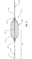
- FIGs 1 and 2 are schematic illustrations of one medical device in accordance with the present invention.
- This medical device comprises a filter system 10 which can be deployed in a channel in a patient's body.
- this filter can be used in any channel in a patient's body, including blood vessels, the urinary tract or biliary tract and airways.
- This filter system 10 is optimally designed to be deployed in a patient's vessel in a minimally invasive procedure, such as by introducing the filter system into a blood vessel through an introducing catheter (not shown in Figures 1 and 2).
- the filter system 10 of the invention generally includes a mandrel 20 and a filter 50.
- the mandrel 20 can be thought of as having a primary function of positioning and controlling the deployment of the filter 50 while the filter can be considered the primary therapeutic or functional element of the system 10.
- the mandrel 20 should be fairly flexible to allow the device to be deployed in a curving body passageway without kinking or otherwise inhibiting suitable deployment of the filter 50. While the mandrel can be formed of any material having any dimension suitable for the task for which the filter system 10 is to be employed, in most circumstances, the mandrel 20 will comprise an elongate metal wire. In one particularly preferred embodiment, the mandrel 20 is formed of nitinol, a roughly stoichiometric alloy of nickel and titanium having excellent "superelastic" properties. The use of nitinol in medical guidewires and related applications is well known in the art and need not be discussed in detail here. If so desired, the distal-most length of the mandrel may include a flexible helically wound coil 22 extending thereover. The use of such helical coils to enhance flexibility of the distal tip is well known in the guidewire art.
- the mandrel 20 has an enlarged diameter stop 40 attached thereto.
- the stop 40 is spaced proximally from the distal tip 25 of the mandrel 20.
- the stop 40 is spaced proximally of the proximal end of the helical coil 22 of the mandrel. This permits the distal slider 60 of the filter 50 to slide relatively freely and unencumbered along the length of the mandrel distally of the stop.
- the stop 40 can be formed of any desired material and can be attached to the mandrel 20 in any desired fashion.
- the stop should be attached to the mandrel relatively securely, though, as the stop will, be used to urge the filter 50 within the lumen of the vessel in which the system 10 is to be deployed.
- the stop 40 may comprise a standard radiopaque marker band which has been securely crimped on the mandrel 20 and/or attached to the mandrel using an adhesive or solder.
- the precise length and shape of the stop 40 is not critical.
- the drawings illustrate the stop 40 as a relatively short cylindrical body attached about the circumference of the mandrel. However, the stop 40 may have a more bulbous shape and could, in theory, even be formed integrally with the mandrel.
- the stop 40 effectively divides the mandrel into distal and proximal lengths.
- the distal length 30 of the mandrel can be thought of as that length which extends distally from the stop 40 to the distal tip 25 of the mandrel.
- the proximal portion 35 of the mandrel 20 can be thought of as comprising the length of the mandrel extending proximally from the stop 40 to the proximal end of the mandrel.
- the filter 50 shown in Figures 1-5 has an elongate, generally tubular body 52 which extends from a distal slider 60 proximally to a proximal slider 65.
- the body 52 of the filter can be formed of any material suitable for the application at hand.
- the filter body 52 typically comprises a length of a braided tubular fabric.
- the use of a tubular braid of nitinol to make medical devices is described in some detail in International Publication No. WO 96/01591.
- this process can employ a tubular braid of a fabric comprising two sets of nitinol wires wrapped helically about a mandrel, with one set of wires being wrapped spirally about the mandrel in one direction and the other set being wrapped in the other direction.
- This braid is then placed in contact with a molding surface of a molding element which defines the shape of the desired functional element.
- the body 52 of the filter 50 desirably is made of a fairly flexible, resilient material.
- the filter 52 desirably has a radially expanded configuration, e.g., the shape shown in Figures 1-3, which the device will tend to resiliently assume in the absence of any countervailing biasing force.
- a body 52 formed of a nitinol tubular braid which has been heat set into the desired shape should suit this purpose well.
- the body 52 of the filter 50 assumes a generally tubular shape having tapered proximal and distal ends.
- the outer diameter of the generally cylindrical middle length of the body 52 should be sized to substantially fill the lumen of a vessel to ensure that the filter will effectively trap any emboli which may be entrained in the patient's bloodstream.
- an alternative configuration of a filter body 152 is illustrated in Figures 7 and 8 and medical devices intended to achieve different clinical objectives are shown in Figures 11 and 12.
- a variety of other filter shapes, as well as shapes of other types of medical devices should be readily apparent to one of ordinary skill in the art in light of the present teachings.
- the filter 50 is attached to or carried by the mandrel 20 by means of a proximal slider 65 attached to the body 52 adjacent its proximal end and a distal slider 60 attached adjacent the distal end of the body 52.
- the distal slider 60 should be free to slide along at least a proximal portion of the distal length 30 of the mandrel while the proximal slider 65 should be free to slide along at least a distal portion of the proximal length 35 of the mandrel.
- the stop 40 of the mandrel effectively defines a limit on the range of motion of these sliders 60, 65.
- each slider 60, 65 should be slidable along its respective length of the mandrel, the sliders can take any desired shape.
- each slider comprises a relatively thin ring which is carried about the mandrel.
- the thin ring can be attached to the body 52 in any desired fashion, such as by crimping or swaging the fabric of the body between two layers of the ring or soldering, welding or otherwise adhering the fabric to the ring.
- the structure of one suitable distal slider is schematically illustrated in a more detailed cross section in Figure 6.
- the proximal slider may have substantially the same configuration, but is not shown in this view simply for purposes of clarity.
- the distal slider 60 comprises a relatively rigid annular ring 61 having an inner component 61 a and an outer component 61b.
- One or both components of the ring 61 is preferably formed of a radiopaque material to enable a physician to better visualize the position of the slider 60 during a procedure.
- the inner component 61 a of the ring is received within the outer component 61b and defines an annular space therebetween.
- the inner diameter of the inner component is larger than the outer diameter of the mandrel 20 to facilitate sliding of the ring 61 with respect thereto.
- Movement of the slider 60 with respect to the mandrel can be further facilitated by coating one or both of the inner surface of the inner component 61 a and the outer surface of the mandrel 20 with a friction-reducing coating, such as Teflon or a lubricious hydrophilic coating.
- a friction-reducing coating such as Teflon or a lubricious hydrophilic coating.
- a distal length of the fabric of the body 52 is received in the annular space between the interior and exterior components 61a and 61b of the ring.
- the fabric is held in place in this space in any suitable manner, e.g. by means of a suitable solder or adhesive or by crimping the fabric between the inner and outer components.
- Figure 6 schematically illustrates both approaches, with the fabric being frictionally grasped between the two components of the ring 61 and held in place by a weldment or adhesive connection 62 at the distal end of the ring.
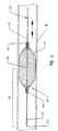
- FIGs 3-5 schematically illustrate the filter system 10 of Figures 1 and 2 in partial cross section.
- the filter 50 is shown in cross section while the mandrel 20 and its components are shown in side view. This is intended to better illustrate the interaction of the stop 40 of the mandrel and the sliders 60, 65 of the filter 50.
- the filter 50 is shown in its radially expanded configuration, which it will tend to assume in the absence of any countervailing biasing force.
- the stop 40 of the mandrel is positioned within the body 52 of the filter and is not exerting any biasing force on either of the sliders 60, 65.
- the mandrel 20 can be moved proximally and distally with respect to the filter 50 without substantially affecting the shape or position of the filter.
- the limits of this range of free movement of the mandrel with respect to the filter are generally defined by the relationship between the stop 40 and the sliders 60, 65.
- the mandrel can be moved from a distal position wherein the stop 40 abuts but does not exert any force on the distal slider 60 and a proximal position wherein the stop 40 abuts, but does not exert any significant force on, the proximal slider 65.
- the filter 50 (or any other functional element which is carried by the mandrel) to be fairly precisely positioned within a patient's vessel and retain that position even if the guidewire is moved slightly during use. This can be advantageous in circumstances where other devices are exchanged over the guidewire (e.g., during angioplasty and atherectomy procedures).
- the inner diameter of the generally annular collars defining the sliders 60, 65 is desirably larger than the outer diameter of the mandrel, as mentioned above. However, the inner diameter of these sliders should be smaller than the outer diameter of the stop 40. In this fashion, the stop serves to limit movement of the sliders. As a consequence, the stop 40 serves as an effective limit on proximal movement of the distal slider 60 and distal movement of the proximal slider 65. Apart from this relationship with the slider 40 and the fact that both sliders are indirectly linked to one another by the body 52 of the filter, the proximal and distal sliders are slidable along the mandrel essentially independently of one another.
- Resilient tubular braids tend to assume a radially reduced profile upon axial elongation. This property and some of its implications are discussed in International Publication No. WO 96/01591, mentioned previously.
- this distal force acts against the restorative force of the resilient braid, which would otherwise bias the braid into its expanded configuration ( Figure 3).
- the body 52 By overcoming this restorative force with a countervailing distal force, the body 52 will tend to both axially elongate and assume a radially reduced profile. This, in turn, reduces the force with which the body engages the wall of the vessel V and reduces friction between the filter 50 and the vessel.
- urging the mandrel distally to move the filter 50 distally will, at the same time, reduce friction between the filter and the vessel wall to further facilitate advancement of the filter along the vessel's lumen.
- This requires less force to push the filter distally, enabling the mandrel to be smaller and reducing the outer diameter of the collapsed device, making deployment in smaller vessels feasible.
- the reduced friction between the filter and the vessel wall limits damage to the intima of the vessel, permitting the filter to be deployed and moved with a minimum of trauma.
- Figure 5 is similar to Figure 4, but schematically illustrates what happens upon proximal retraction of the mandrel.
- the stop 40 of the mandrel abuts against and exerts a proximal biasing force on, the proximal slider 65 of the filter 50.
- this proximal biasing force will act against the restorative force of the body 52 to axially elongate and radially reduce that body. This permits the device to be withdrawn proximally along the lumen of the vessel either for repositioning at a more proximal location or for withdrawal from the patient's body at the end of the procedure.
- the proximal and distal sliders 60, 65 are free to move relatively independently of one another, limited primarily by their indirect link to one another through the body 52 of the filter.
- the proximal slider will slide proximally along the proximal length 35 of the mandrel.
- the distal slider will be free to drift distally along the distal length 30 of the mandrel.
- FIG. 3 Another salient aspect of the device highlighted in Figures 3-5 is that the spacing between the sliders 60 and 65 changes in response to the mandrel acting against one of the sliders.
- the proximal and distal sliders are spaced a first distance from one another, with the body 52 engaging the wall of the vessel.
- the stop 40 of the mandrel urges against one of the sliders, though, the body 52 will tend to axially elongate and the distance between the two sliders will increase.
- Figures 9 and 10 schematically illustrate certain advantages of the present invention when deploying and retrieving the device in a body channel using a catheter.
- Figure 9 schematically shows the device of Figures 1-5 being deployed through a catheter C.
- a length of the mandrel 20 and the entirety of the filter 50 is received within the lumen of the catheter C.
- the mandrel 20 is being urged distally to exit the distal end of the catheter C.
- the stop 40 is exerting a distal biasing force against the distal slider 60 within the relatively close confines of the catheter C.
- the body 52 of the filter 50 will exert an outward force against the interior surface of the catheter C, increasing friction between the filter and the catheter C.
- FIG. 10 schematically illustrates retrieval of the device of Figures 1-5 and 9 which has already been deployed in a patient's vessel.
- the filter 50 is being withdrawn proximally into the lumen of the catheter C. This can be initiated by positioning the distal end of the catheter C just proximal of the proximal slider 65 and then moving the catheter C with respect to the stop 40. This can be accomplished either by urging the catheter C distally or withdrawing the mandrel 20 proximally, as the operator sees fit at the time.
- the catheter C will frictionally engage and will tend to radially compress the body 52 of the filter.
- the slider 65 will be brought in contact with the stop 40. Further movement of the catheter C with respect to the mandrel will urge more of the length of the body 52 into the lumen of the catheter C.
- the distal slider 60 may slide distally along the distal length 30 of the mandrel, permitting the body 52 to axially elongate in response to the radial compression induced by the catheter C.
- the body 52 of the filter will axially elongate and radially reduce in response to movement of the mandrel 20 with respect to the catheter C.
- the stop 40 urges distally against the distal slider 60, effectively pushing the filter 50 distally along the catheter C.
- the stop 40 can be seen as pushing proximally on the proximal slider 65. Again, this biasing force will tend to axially elongate and radially reduce the body 52 of the filter.
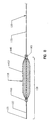
- Figures 7 and 8 illustrate an alternative embodiment of the invention.
- Figures 1-6 refer to a filter system 10 having a mandrel 20;
- Figures 7 and 8 show a filter system 110 having a mandrel 120.
- the primary difference between the filter 150 of Figures 7 and 8 and the filter 50 of Figures 1-6 is the shape of the filter in its fully radially expanded configuration.
- the filter 50 has a generally tubular body with spaced-apart tapered ends.
- the filter 150 of Figures 7 and 8 has a generally umbrella-shaped body 152, with a proximal length of the fabric defining the body being inverted and received within the interior of the distal portion of the fabric.
- the distal slider 160 and proximal slider 165 are positioned much more closely to one another in the fully deployed filter 150, shown in Figure 7, than are the spacers 60, 65 in the fully deployed filter 50, shown in Figures 1-3.
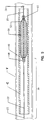
- Figure 8 illustrates the filter 150 in an axially elongated, radially reduced state induced by withdrawing the mandrel 120 proximally.
- the stop 140 will abut and urge proximally against the proximal slider 165.
- this tends to axially elongate the body 52 of that filter 50 without any substantial change in the shape of the filter.
- the filter 150 of Figures 7 and 8 is more complex in its fully deployed, expanded state (shown in Figure 7).
- the proximal length of the fabric which is received within the interior of the distal portion of the fabric will tend to evert.
- the distal portion of the fabric i.e., the outer portion of the fabric shown in Figure 7
- the shape of the interior surface of the umbrella will change first without any significant change in the external shape.
- the body 152 will take on a shape which looks more like the shape of the filter 50 of the previous embodiment.
- proximal slider 165 will further elongate the body until it reaches a shape such as that schematically illustrated in Figure 8. This makes withdrawal of the trap easier, but care should be taken to ensure that any particular material retained within the interior of the umbrella-like body 152 is not inadvertently dumped back into the patient's bloodstream. This can be done, for example, by breaking down trapped thrombus using clot-busting drugs or by aspirating the particulate material through a catheter before proximally withdrawing the mandrel 120.
- a catheter C is urged distally along the proximal length 135 of the mandrel until the distal tip of the catheter (not shown in Figures 7 and 8) is positioned in the interior of the umbrella-like filter body 152. If necessary, any particulate material within that interior can be aspirated through the catheter C and out of the patient's body. Thereafter, the mandrel can be withdrawn proximally, drawing the proximal slider 165 into the interior of the catheter C. As discussed above in connection with Figure 10, this will help collapse the body 152 of the filter into the lumen of the catheter C.
- the catheter C can be held in the same position while the rest of the filter 150 is drawn inside.
- the catheter C and the mandrel can be withdrawn together as a unit a short distance so that the distal tip of the catheter C is positioned slightly proximal of the proximal edge of the deployed filter shown in Figure 7. This will further facilitate drawing the body 152 down into the lumen of the catheter C.
- the catheter, the filter and the mandrel 120 can be withdrawn together as a unit from the patient's body.
- Figure 11 shows a medical device which is similar to the embodiment shown in Figures 1-5, 9 and 10.
- the shape of the body 52' of the plug 50' has a significantly different shape from the body 52 of the filter 50 discussed above. Whereas the majority of the length of the filter 50 would assume a relatively constant diameter if left unconstrained, the body 52' of the plug 50' has a more complex shape. While this device can also be used to filter fluid which is passing through a vessel, its design is particularly well-suited to occlude a vessel either temporarily or permanently.
- a method for making and using a vascular occlusion device having a shape similar to that of the body 52' of Figure 11 is disclosed in International Publication No. WO 96/01591. Briefly, though, this body 52' includes a pair of spaced-apart enlarged diameter sections separated by a central section having a reduced diameter. If so desired, the surface of this device may be coated with a thrombogenic agent or nylon fibers or the like can be attached to the body 52'. Conversely, if the plug 50' or the filter 50 are to be used solely for purposes of filtering fluids passing therethrough and it is preferred that any blood passing through the functional element not clot thereon, the body can be coated with an anti-thrombogenic agent.
- the plug 50' of Figure 11 can be used as a temporary occlusion device and withdrawn at the end of a procedure or treatment course. In other circumstances, though, it may be preferred to more permanently occlude the channel in which the plug 50' is deployed. While the stop 40 abutting against the sliders 60, 65 facilitates deployment and repositioning, the attachment of the stop 40 to the mandrel 20 could effectively prevent one from removing the mandrel from the plug.
- the mandrel 20 can be withdrawn either partially or entirely from the plug in a variety of different manners.
- the proximal portion 35 of the mandrel can be releasably attached to the stop 40, e.g., by means of a threaded engagement therebetween.
- the distal section 30 Without somehow locking the distal section 30 against rotation (e.g., by a splined connection between the distal section 30 and the distal slider 60), though, it can be difficult to disconnect these parts from one another.
- Figure 12 illustrates one preferred embodiment of a stop 40' which may be used to withdraw the mandrel 20 while leaving the filter 50 or plug 50' in place in the patient's body.
- the stop 40 and the proximal slider 65 were both essentially annular in shape, with the relatively constant outer diameter of the stop being greater than the relatively constant inner diameter of the slider. As a consequence, one cannot readily withdraw the stop 40 from within the enclosure of the body 52 of the filter 50.
- the stop 40' of Figure 12 can be withdrawn from the interior of a filter 50, plug 50' or other device having a suitably adapted proximal slider.
- the stop 40' includes an external thread 42' which extends spirally outwardly from the main body 44' of the stop.
- the proximal slider (not shown in this view) has a threaded internal surface which is sized and shaped to mate with the outer thread 42' on the stop 40'. Aside from the spiral slot or keyway shaped to receive the thread 42' of the stop, the inner diameter of the proximal slider should be slightly greater than the outer diameter of the body 44' of the stop but less than the maximum diameter of the stop including the thread 42'. During normal operation, this will ensure that the stop 40' will abut against the proximal slider so the device will operate as described above.
- the mandrel can be withdrawn from the filter or plug by pulling the mandrel proximally until the stop 40 lightly abuts the proximal slider. Rotating the mandrel about its axis will permit the thread 42' to travel along the slot in the proximal slider. In this manner, the stop can be withdrawn through the proximal slider and the mandrel can be completely removed from the patient's body, leaving the medical device in place within the vessel.
- the medical device is introduced into a vessel in a patient's body.
- this would comprise inserting the distal end 25 of the mandrel 20 into the lumen of the patient's vessel V. This may be done either directly or, more commonly, by using an introducer sheath. Such introducer sheaths are commonly used in introducing medical devices for minimally invasive procedures.
- the mandrel can be urged distally to introduce the functional element, i.e., filter 50 in Figures 1-5, into the vessel, as well.
- the filter 50 may be urged distally along the lumen of the vessel V to a predetermined treatment site.
- the treatment site may, for example, simply be a convenient location in a patient's vasculature positioned distally of an obstruction which will be treated with an angioplasty balloon or an atherectomy device.
- the filter 50 can be advanced along the vessel by urging the mandrel distally such that the stop 40 engages the distal slider 60. This exerts a distal biasing force on the distal slider which, in turn, acts against a restorative force of the body 52 of the filter.
- the body 52 will tend to axially elongate and take on a radially reduced profile. This reduces friction between the filter 50 and the wall of the vessel, facilitating advancement therealong.
- the axial force against the mandrel can simply be released. This will permit the body 52 to expand radially and axially contract, drawing the two sliders 60, 65 toward one another along the mandrel. If it is determined that the filter is not precisely positioned in the desired treatment site, it can be readily repositioned by pushing the mandrel distally or withdrawing it proximally and again allowing the filter to self-expand radially and self-contract axially once the mandrel stops acting against the sliders.
- the operator can simply pull proximally on the mandrel to radially contract the device and facilitate proximal movement within the vessel, as shown in Figure 5.
- a catheter may be positioned adjacent a treatment site in a patient's body. This can be done in any desired fashion.
- the mandrel 20 and the catheter can be advanced simultaneously through the patient's vessel.
- the catheter will be positioned at the desired treatment site before the mandrel 20 is inserted into the catheter. This permits the operator to steer the catheter into place without hindrance from the mandrel or to track the catheter over a guidewire if the desired treatment site is positioned in a narrower or more tortuous vessel, after which the guidewire can be removed.
- the distal tip 25 of the mandrel can be inserted into the proximal end (not shown) of the catheter outside the patient's body.
- the catheter will frictionally engage the body 52 of the filter. Further distal urging of the mandrel will cause the stop 40 to exert a distal biasing force on the distal slider 60.
- this distal biasing force will tend to axially elongate and radially reduce the body 52, further facilitating entry of the body into the lumen of the catheter.
- the filter 50 may continue to be urged distally along the length of the catheter.
- the distal urging of the stop 40 against the distal slider 60 will axially elongate and radially reduce the body, reducing friction between the body and the catheter during such advancement.
- the mandrel can be urged distally until the device exits the distal end of the catheter.
- the body will then tend to radially self-expand until it reaches a radially-expanded shape wherein it may engage the walls of the vessel (B in Figure 9).
- the distal tip of the catheter may be positioned distally of the desired treatment site.
- advancement of the mandrel can be stopped when the operator determines by means of the radiopaque sliders 60, 65 that the filter is in the desired treatment site.
- the catheter can be withdrawn proximally while holding the mandrel 20 in place.
- the body will tend to radially self-expand with the distal slider 60 remaining in substantially the same place due to its abutment against the stop 40.
- the mandrel be withdrawn from the patient's body either in part or in its entirety.
- the distal most of those lengths can be detached from one another, leaving the filter 50 and the distal-most length in the patient's body while withdrawing the proximal-most length.
- These lengths can be connected in any fashion known in the art, such as by means of a threaded engagement or by means of a solder which can be melted or softened by application of electrical resistance heating of the mandrel.
- the entire mandrel 20 is withdrawn from the patient's body. This can be done by withdrawing the stop 40 through the proximal slider 65 of the filter.
- One suitable stop 40' is shown in Figure 12. This stop 40', used in conjunction with a specially adapted proximal slider (not shown, but described above) can be used to withdraw the stop through the proximal slider for removal of the mandrel. As explained previously, this can be accomplished by bringing the stop 40' into abutting engagement with the proximal slider then rotating the mandrel 20 about its axis. This will cause the thread 42' extending radially outwardly from the body 44' of the stop to pass along a mating slot in the proximal slider.
- the mandrel After the mandrel has been rotated sufficiently to completely withdraw the stop through the proximal slider, the mandrel can easily be withdrawn from the body by withdrawing the distal portion 30 of the mandrel proximally through the center of the filter body 52 and out of the patient's body entirely.
- the filter 50 can be withdrawn into the lumen of the catheter C either by holding the mandrel stationary and advancing the catheter distally over the filter 50 or by holding the catheter in a fixed position and withdrawing the mandrel 20 proximally.
- the proximal urging of the stop 40 against the proximal slider 65 tends to axially elongate and radially reduce the body 52, both facilitating entry of the body 52 into the lumen of the catheter and reducing friction between the catheter and the length of the body 52 which is already received therein.
Abstract
Description
Claims (17)
- A collapsible medical device, comprising:(a) a mandrel (20, 120) having a distal end (25, 125) and a stop (40, 140, 40') spaced proximally of the distal end, a proximal length (35, 135) of the mandrel extending proximally of the stop and a distal length (30, 130) of the mandrel extending distally of the stop; and(b) a functional element (50, 150, 50') comprising a radially expandable body (52, 152, 52') having a proximal slider (65, 165) and a distal slider (60, 160), the proximal slider being slidably carried along the proximal length of the mandrel and, the proximal and distal sliders being slidable along the mandrel independently of one another such that the distance between the proximal slider and distal slider can be varied to effect different configurations of the functional element, characterized in that the distal slider being slidably carried along the distal length of the mandrel.
- The medical device of Claim 1, wherein the functional element (50, 150, 50') has an expanded configuration and is capable of being collapsed for passage along a lumen, the functional element being adapted to resiliently return toward the expanded configuration in the absence of any biasing force.
- The medical device of Claim 1 or Claim 2, arranged such that the body (52, 152, 52') of the functional element assumes a radially reduced configuration when the distance between the proximal slider and the distal slider is increased.
- The medical device of Claim 3, arranged such that, in use, the stop (40, 140, 40') abuts the proximal slider and exerts a proximal biasing force thereon, such proximal biasing force acting against a restorative force of the body to axially elongate and radially reduce the body.
- The medical device of Claim 3 or 4, arranged such that, in use, the stop (40, 140, 40') abuts the distal slider and exerts a distal biasing force thereon, such distal biasing force acting against a restorative force of the body to axially elongate and radially reduce the body.
- The medical device of any one of the preceding claims, further comprising a control sheath (C), the body being collapsible within the sheath with the proximal and distal sliders spaced from one another.
- The medical device of Claim 6, wherein a wall of the control sheath is arranged to exert a biasing force against a radially restorative force of the body, such biasing force maintaining a space between the proximal and distal sliders.
- The collapsible medical device according to any one of the preceding claims, in which the functional element (50, 150, 50') is formed of a resilient tubular braid which has a preferred radially expanded configuration but will assume a radially reduced profile upon axial elongation.
- The medical device of Claim 8, wherein the stop (40, 140, 40') has an external diameter larger than an internal diameter of either the proximal slider or the distal slider.
- The medical device of Claim 8, wherein the stop (40, 140, 40') is sized to urge distally against the distal slider upon distal urging of the mandrel.
- A filter system for temporary deployment in a channel of a patient's body, comprising the collapsible medical device of any one of Claims 8 to 10 in which the resilient tubular braid forms a filter element (50, 150, 50'), the filter having a collapsed configuration wherein the sliders are spaced from one another a first distance along the mandrel and the filter has a first diameter, and an expanded configuration wherein the sliders are spaced a second, shorter distance along the mandrel and the filter has a second diameter, the first diameter being less than the second diameter.
- The filter system of Claim 11, wherein each of the proximal and distal sliders comprises an annular collar (61) having an inner diameter larger than an outer diameter of the mandrel but smaller than an outer diameter of the stop, the stop thereby serving to limit movement of the sliders.
- The filter system of Claim 11 or Claim 12, wherein the proximal and distal sliders are slidable along the mandrel independently of one another.
- The filter system of any one of Claims 11 to 13, arranged such that, in use, the stop abuts the proximal slider and exerts a proximal biasing force thereon, such proximal biasing force acting against a restorative force of the filter to axially elongate and radially reduce the filter.
- The filter system of any one of Claims 11 to 14, arranged such that, in use, the stop abuts the distal slider and exerts a distal biasing force thereon, such distal biasing force acting against a restorative force of the filter to axially elongate and radially reduce the filter.
- The medical device of any one of the preceding claims, were in the proximal slider comprises a proximal annular ring defining an opening having an inner diameter and the distal slider comprises a distal annular ring defining an opening having an inner diameter and wherein the inner diameter of the openings in a proximal and distal annular rings are substantially equal.
- The medical device of any of the preceding claims, wherein the proximal length of the mandrel has a proximal diameter and the distal length of the mandrel has a distal diameter and wherein the proximal and distal diameters are substantially equal.
Priority Applications (3)
| Application Number | Priority Date | Filing Date | Title |
|---|---|---|---|
| AT03078893T ATE410975T1 (en) | 1999-08-27 | 1999-08-27 | SLIDING VASCULAR FILTER |
| ES99945357T ES2209503T3 (en) | 1999-08-27 | 1999-08-27 | FOLDING MEDICAL DEVICE. |
| EP03078893.9A EP1402848B2 (en) | 1999-08-27 | 1999-08-27 | Slideable vascular filter |
Applications Claiming Priority (1)
| Application Number | Priority Date | Filing Date | Title |
|---|---|---|---|
| PCT/US1999/019942 WO2001015629A1 (en) | 1999-08-27 | 1999-08-27 | Slideable vascular filter |
Related Child Applications (1)
| Application Number | Title | Priority Date | Filing Date |
|---|---|---|---|
| EP03078893.9A Division EP1402848B2 (en) | 1999-08-27 | 1999-08-27 | Slideable vascular filter |
Publications (2)
| Publication Number | Publication Date |
|---|---|
| EP1210032A1 EP1210032A1 (en) | 2002-06-05 |
| EP1210032B1 true EP1210032B1 (en) | 2003-12-17 |
Family
ID=22273499
Family Applications (2)
| Application Number | Title | Priority Date | Filing Date |
|---|---|---|---|
| EP03078893.9A Expired - Lifetime EP1402848B2 (en) | 1999-08-27 | 1999-08-27 | Slideable vascular filter |
| EP99945357A Expired - Lifetime EP1210032B1 (en) | 1999-08-27 | 1999-08-27 | Slidable vascular filter |
Family Applications Before (1)
| Application Number | Title | Priority Date | Filing Date |
|---|---|---|---|
| EP03078893.9A Expired - Lifetime EP1402848B2 (en) | 1999-08-27 | 1999-08-27 | Slideable vascular filter |
Country Status (8)
| Country | Link |
|---|---|
| US (11) | US20020111648A1 (en) |
| EP (2) | EP1402848B2 (en) |
| JP (1) | JP4298949B2 (en) |
| AT (2) | ATE256436T1 (en) |
| AU (1) | AU5796899A (en) |
| DE (2) | DE69939753D1 (en) |
| ES (2) | ES2209503T3 (en) |
| WO (1) | WO2001015629A1 (en) |
Cited By (2)
| Publication number | Priority date | Publication date | Assignee | Title |
|---|---|---|---|---|
| US9592068B2 (en) | 2013-03-15 | 2017-03-14 | Insera Therapeutics, Inc. | Free end vascular treatment systems |
| US10251739B2 (en) | 2013-03-15 | 2019-04-09 | Insera Therapeutics, Inc. | Thrombus aspiration using an operator-selectable suction pattern |
Families Citing this family (279)
| Publication number | Priority date | Publication date | Assignee | Title |
|---|---|---|---|---|
| DE69529338T3 (en) | 1994-07-08 | 2007-05-31 | Ev3 Inc., Plymouth | Intravascular filter device |
| EP0934092A4 (en) | 1997-03-06 | 2008-03-26 | Boston Scient Scimed Inc | Distal protection device and method |
| US7491216B2 (en) | 1997-11-07 | 2009-02-17 | Salviac Limited | Filter element with retractable guidewire tip |
| DE69838952T2 (en) | 1997-11-07 | 2009-01-02 | Salviac Ltd. | EMBOLISM PROTECTION DEVICE |
| US7314477B1 (en) | 1998-09-25 | 2008-01-01 | C.R. Bard Inc. | Removable embolus blood clot filter and filter delivery unit |
| US7713282B2 (en) | 1998-11-06 | 2010-05-11 | Atritech, Inc. | Detachable atrial appendage occlusion balloon |
| US7044134B2 (en) | 1999-11-08 | 2006-05-16 | Ev3 Sunnyvale, Inc | Method of implanting a device in the left atrial appendage |
| US7128073B1 (en) | 1998-11-06 | 2006-10-31 | Ev3 Endovascular, Inc. | Method and device for left atrial appendage occlusion |
| US6171327B1 (en) | 1999-02-24 | 2001-01-09 | Scimed Life Systems, Inc. | Intravascular filter and method |
| US6918921B2 (en) | 1999-05-07 | 2005-07-19 | Salviac Limited | Support frame for an embolic protection device |
| US6964672B2 (en) | 1999-05-07 | 2005-11-15 | Salviac Limited | Support frame for an embolic protection device |
| US20030150821A1 (en) * | 1999-07-16 | 2003-08-14 | Bates Mark C. | Emboli filtration system and methods of use |
| US6544279B1 (en) | 2000-08-09 | 2003-04-08 | Incept, Llc | Vascular device for emboli, thrombus and foreign body removal and methods of use |
| DE69939753D1 (en) | 1999-08-27 | 2008-11-27 | Ev3 Inc | Movable vascular filter |
| US6325815B1 (en) * | 1999-09-21 | 2001-12-04 | Microvena Corporation | Temporary vascular filter |
| US6217589B1 (en) | 1999-10-27 | 2001-04-17 | Scimed Life Systems, Inc. | Retrieval device made of precursor alloy cable and method of manufacturing |
| US6575997B1 (en) | 1999-12-23 | 2003-06-10 | Endovascular Technologies, Inc. | Embolic basket |
| US6402771B1 (en) | 1999-12-23 | 2002-06-11 | Guidant Endovascular Solutions | Snare |
| US6660021B1 (en) | 1999-12-23 | 2003-12-09 | Advanced Cardiovascular Systems, Inc. | Intravascular device and system |
| US7918820B2 (en) | 1999-12-30 | 2011-04-05 | Advanced Cardiovascular Systems, Inc. | Device for, and method of, blocking emboli in vessels such as blood arteries |
| US6695813B1 (en) | 1999-12-30 | 2004-02-24 | Advanced Cardiovascular Systems, Inc. | Embolic protection devices |
| US6540722B1 (en) * | 1999-12-30 | 2003-04-01 | Advanced Cardiovascular Systems, Inc. | Embolic protection devices |
| US20040167567A1 (en) * | 2001-03-23 | 2004-08-26 | Cano Gerald G. | Method and apparatus for capturing objects beyond an operative site in medical procedures |
| GB2369575A (en) | 2000-04-20 | 2002-06-05 | Salviac Ltd | An embolic protection system |
| US6964670B1 (en) | 2000-07-13 | 2005-11-15 | Advanced Cardiovascular Systems, Inc. | Embolic protection guide wire |
| US6537294B1 (en) * | 2000-10-17 | 2003-03-25 | Advanced Cardiovascular Systems, Inc. | Delivery systems for embolic filter devices |
| US6893451B2 (en) * | 2000-11-09 | 2005-05-17 | Advanced Cardiovascular Systems, Inc. | Apparatus for capturing objects beyond an operative site utilizing a capture device delivered on a medical guide wire |
| US6506203B1 (en) | 2000-12-19 | 2003-01-14 | Advanced Cardiovascular Systems, Inc. | Low profile sheathless embolic protection system |
| US6974468B2 (en) | 2001-02-28 | 2005-12-13 | Scimed Life Systems, Inc. | Filter retrieval catheter |
| US6818006B2 (en) * | 2001-04-03 | 2004-11-16 | Medtronic Vascular, Inc. | Temporary intraluminal filter guidewire |
| US6645223B2 (en) * | 2001-04-30 | 2003-11-11 | Advanced Cardiovascular Systems, Inc. | Deployment and recovery control systems for embolic protection devices |
| US6929652B1 (en) * | 2001-06-01 | 2005-08-16 | Advanced Cardiovascular Systems, Inc. | Delivery and recovery systems having steerability and rapid exchange operating modes for embolic protection systems |
| US7338514B2 (en) | 2001-06-01 | 2008-03-04 | St. Jude Medical, Cardiology Division, Inc. | Closure devices, related delivery methods and tools, and related methods of use |
| US7338510B2 (en) * | 2001-06-29 | 2008-03-04 | Advanced Cardiovascular Systems, Inc. | Variable thickness embolic filtering devices and method of manufacturing the same |
| US6599307B1 (en) | 2001-06-29 | 2003-07-29 | Advanced Cardiovascular Systems, Inc. | Filter device for embolic protection systems |
| US20030032941A1 (en) * | 2001-08-13 | 2003-02-13 | Boyle William J. | Convertible delivery systems for medical devices |
| US6638294B1 (en) | 2001-08-30 | 2003-10-28 | Advanced Cardiovascular Systems, Inc. | Self furling umbrella frame for carotid filter |
| US6592606B2 (en) | 2001-08-31 | 2003-07-15 | Advanced Cardiovascular Systems, Inc. | Hinged short cage for an embolic protection device |
| US6802851B2 (en) * | 2001-09-20 | 2004-10-12 | Gordia Neurovascular, Inc. | Stent aneurysm embolization method using collapsible member and embolic coils |
| US6811560B2 (en) * | 2001-09-20 | 2004-11-02 | Cordis Neurovascular, Inc. | Stent aneurysm embolization method and device |
| US6878151B2 (en) * | 2001-09-27 | 2005-04-12 | Scimed Life Systems, Inc. | Medical retrieval device |
| US8262689B2 (en) | 2001-09-28 | 2012-09-11 | Advanced Cardiovascular Systems, Inc. | Embolic filtering devices |
| US20030078614A1 (en) * | 2001-10-18 | 2003-04-24 | Amr Salahieh | Vascular embolic filter devices and methods of use therefor |
| US6887257B2 (en) | 2001-10-19 | 2005-05-03 | Incept Llc | Vascular embolic filter exchange devices and methods of use thereof |
| US6890340B2 (en) | 2001-11-29 | 2005-05-10 | Medtronic Vascular, Inc. | Apparatus for temporary intraluminal protection |
| US7241304B2 (en) | 2001-12-21 | 2007-07-10 | Advanced Cardiovascular Systems, Inc. | Flexible and conformable embolic filtering devices |
| WO2003055412A2 (en) | 2001-12-21 | 2003-07-10 | Salviac Limited | A support frame for an embolic protection device |
| US9204956B2 (en) | 2002-02-20 | 2015-12-08 | C. R. Bard, Inc. | IVC filter with translating hooks |
| US7192434B2 (en) | 2002-03-08 | 2007-03-20 | Ev3 Inc. | Vascular protection devices and methods of use |
| US6773448B2 (en) | 2002-03-08 | 2004-08-10 | Ev3 Inc. | Distal protection devices having controllable wire motion |
| US20030176884A1 (en) | 2002-03-12 | 2003-09-18 | Marwane Berrada | Everted filter device |
| US20030187495A1 (en) | 2002-04-01 | 2003-10-02 | Cully Edward H. | Endoluminal devices, embolic filters, methods of manufacture and use |
| US7976564B2 (en) | 2002-05-06 | 2011-07-12 | St. Jude Medical, Cardiology Division, Inc. | PFO closure devices and related methods of use |
| WO2003097122A2 (en) | 2002-05-14 | 2003-11-27 | Bacchus Vascular, Inc. | Apparatus and method for removing occlusive material within blood vessels |
| US6887258B2 (en) * | 2002-06-26 | 2005-05-03 | Advanced Cardiovascular Systems, Inc. | Embolic filtering devices for bifurcated vessels |
| US7172614B2 (en) * | 2002-06-27 | 2007-02-06 | Advanced Cardiovascular Systems, Inc. | Support structures for embolic filtering devices |
| US7166120B2 (en) | 2002-07-12 | 2007-01-23 | Ev3 Inc. | Catheter with occluding cuff |
| DE10233085B4 (en) | 2002-07-19 | 2014-02-20 | Dendron Gmbh | Stent with guide wire |
| EP1402826B1 (en) * | 2002-08-20 | 2013-06-12 | Nipro Corporation | Thrombus capture catheter |
| US7056328B2 (en) * | 2002-09-18 | 2006-06-06 | Arnott Richard J | Apparatus for capturing objects beyond an operative site utilizing a capture device delivered on a medical guide wire |
| US20040064099A1 (en) * | 2002-09-30 | 2004-04-01 | Chiu Jessica G. | Intraluminal needle injection substance delivery system with filtering capability |
| US7331973B2 (en) * | 2002-09-30 | 2008-02-19 | Avdanced Cardiovascular Systems, Inc. | Guide wire with embolic filtering attachment |
| US7252675B2 (en) * | 2002-09-30 | 2007-08-07 | Advanced Cardiovascular, Inc. | Embolic filtering devices |
| US20040093012A1 (en) | 2002-10-17 | 2004-05-13 | Cully Edward H. | Embolic filter frame having looped support strut elements |
| US20040088000A1 (en) * | 2002-10-31 | 2004-05-06 | Muller Paul F. | Single-wire expandable cages for embolic filtering devices |
| US20040102789A1 (en) * | 2002-11-22 | 2004-05-27 | Scimed Life Systems, Inc. | Selectively locking device |
| US7128752B2 (en) | 2002-12-23 | 2006-10-31 | Syntheon, Llc | Emboli and thrombi filter device and method of using the same |
| US7220271B2 (en) | 2003-01-30 | 2007-05-22 | Ev3 Inc. | Embolic filters having multiple layers and controlled pore size |
| US7323001B2 (en) | 2003-01-30 | 2008-01-29 | Ev3 Inc. | Embolic filters with controlled pore size |
| US20040153119A1 (en) | 2003-01-30 | 2004-08-05 | Kusleika Richard S. | Embolic filters with a distal loop or no loop |
| US6878291B2 (en) | 2003-02-24 | 2005-04-12 | Scimed Life Systems, Inc. | Flexible tube for cartridge filter |
| US7740644B2 (en) | 2003-02-24 | 2010-06-22 | Boston Scientific Scimed, Inc. | Embolic protection filtering device that can be adapted to be advanced over a guidewire |
| US8591540B2 (en) | 2003-02-27 | 2013-11-26 | Abbott Cardiovascular Systems Inc. | Embolic filtering devices |
| US20040172055A1 (en) * | 2003-02-27 | 2004-09-02 | Huter Scott J. | Embolic filtering devices |
| US6902572B2 (en) * | 2003-04-02 | 2005-06-07 | Scimed Life Systems, Inc. | Anchoring mechanisms for intravascular devices |
| US8372112B2 (en) | 2003-04-11 | 2013-02-12 | St. Jude Medical, Cardiology Division, Inc. | Closure devices, related delivery methods, and related methods of use |
| US20040267306A1 (en) | 2003-04-11 | 2004-12-30 | Velocimed, L.L.C. | Closure devices, related delivery methods, and related methods of use |
| US6969396B2 (en) * | 2003-05-07 | 2005-11-29 | Scimed Life Systems, Inc. | Filter membrane with increased surface area |
| US7879062B2 (en) * | 2003-07-22 | 2011-02-01 | Lumen Biomedical, Inc. | Fiber based embolism protection device |
| US7035438B2 (en) * | 2003-07-30 | 2006-04-25 | Xerox Corporation | System and method for measuring and quantizing document quality |
| US9301829B2 (en) | 2003-07-30 | 2016-04-05 | Boston Scientific Scimed, Inc. | Embolic protection aspirator |
| US7735493B2 (en) | 2003-08-15 | 2010-06-15 | Atritech, Inc. | System and method for delivering a left atrial appendage containment device |
| US7892251B1 (en) | 2003-11-12 | 2011-02-22 | Advanced Cardiovascular Systems, Inc. | Component for delivering and locking a medical device to a guide wire |
| US7056286B2 (en) * | 2003-11-12 | 2006-06-06 | Adrian Ravenscroft | Medical device anchor and delivery system |
| US8147561B2 (en) | 2004-02-26 | 2012-04-03 | Endosphere, Inc. | Methods and devices to curb appetite and/or reduce food intake |
| US7931693B2 (en) * | 2004-02-26 | 2011-04-26 | Endosphere, Inc. | Method and apparatus for reducing obesity |
| US8585771B2 (en) | 2004-02-26 | 2013-11-19 | Endosphere, Inc. | Methods and devices to curb appetite and/or to reduce food intake |
| US7988705B2 (en) * | 2004-03-06 | 2011-08-02 | Lumen Biomedical, Inc. | Steerable device having a corewire within a tube and combination with a functional medical component |
| US7678129B1 (en) | 2004-03-19 | 2010-03-16 | Advanced Cardiovascular Systems, Inc. | Locking component for an embolic filter assembly |
| WO2005094283A2 (en) | 2004-03-25 | 2005-10-13 | Hauser David L | Vascular filter device |
| US20060206200A1 (en) | 2004-05-25 | 2006-09-14 | Chestnut Medical Technologies, Inc. | Flexible vascular occluding device |
| WO2010120926A1 (en) | 2004-05-25 | 2010-10-21 | Chestnut Medical Technologies, Inc. | Vascular stenting for aneurysms |
| US8617234B2 (en) | 2004-05-25 | 2013-12-31 | Covidien Lp | Flexible vascular occluding device |
| JP2008502378A (en) | 2004-05-25 | 2008-01-31 | チェストナット メディカル テクノロジーズ インコーポレイテッド | Flexible vascular closure device |
| US8628564B2 (en) | 2004-05-25 | 2014-01-14 | Covidien Lp | Methods and apparatus for luminal stenting |
| US20060020285A1 (en) * | 2004-07-22 | 2006-01-26 | Volker Niermann | Method for filtering blood in a vessel with helical elements |
| US7704267B2 (en) | 2004-08-04 | 2010-04-27 | C. R. Bard, Inc. | Non-entangling vena cava filter |
| WO2006034233A1 (en) * | 2004-09-20 | 2006-03-30 | Cook, Inc. | Anti-thrombus filter having enhanced identifying features |
| WO2006042114A1 (en) | 2004-10-06 | 2006-04-20 | Cook, Inc. | Emboli capturing device having a coil and method for capturing emboli |
| US7794473B2 (en) * | 2004-11-12 | 2010-09-14 | C.R. Bard, Inc. | Filter delivery system |
| US20080147111A1 (en) * | 2005-01-03 | 2008-06-19 | Eric Johnson | Endoluminal Filter With Fixation |
| US20060241677A1 (en) * | 2005-01-03 | 2006-10-26 | Eric Johnson | Methods for maintaining a filtering device within a lumen |
| US8029529B1 (en) | 2005-01-19 | 2011-10-04 | C. R. Bard, Inc. | Retrievable filter |
| US8267954B2 (en) | 2005-02-04 | 2012-09-18 | C. R. Bard, Inc. | Vascular filter with sensing capability |
| ATE539789T1 (en) | 2005-02-18 | 2012-01-15 | Tyco Healthcare | QUICKLY REPLACEABLE CATHETER |
| US8221446B2 (en) | 2005-03-15 | 2012-07-17 | Cook Medical Technologies | Embolic protection device |
| US8945169B2 (en) | 2005-03-15 | 2015-02-03 | Cook Medical Technologies Llc | Embolic protection device |
| US20060224175A1 (en) * | 2005-03-29 | 2006-10-05 | Vrba Anthony C | Methods and apparatuses for disposition of a medical device onto an elongate medical device |
| US9259305B2 (en) | 2005-03-31 | 2016-02-16 | Abbott Cardiovascular Systems Inc. | Guide wire locking mechanism for rapid exchange and other catheter systems |
| US8025668B2 (en) * | 2005-04-28 | 2011-09-27 | C. R. Bard, Inc. | Medical device removal system |
| US7967747B2 (en) * | 2005-05-10 | 2011-06-28 | Boston Scientific Scimed, Inc. | Filtering apparatus and methods of use |
| US8696662B2 (en) * | 2005-05-12 | 2014-04-15 | Aesculap Ag | Electrocautery method and apparatus |
| CA2607580C (en) | 2005-05-12 | 2016-12-20 | C.R. Bard Inc. | Removable embolus blood clot filter |
| AU2005332044B2 (en) | 2005-05-25 | 2012-01-19 | Covidien Lp | System and method for delivering and deploying and occluding device within a vessel |
| US8109962B2 (en) | 2005-06-20 | 2012-02-07 | Cook Medical Technologies Llc | Retrievable device having a reticulation portion with staggered struts |
| US7850708B2 (en) | 2005-06-20 | 2010-12-14 | Cook Incorporated | Embolic protection device having a reticulated body with staggered struts |
| US20080058856A1 (en) * | 2005-06-28 | 2008-03-06 | Venkatesh Ramaiah | Non-occluding dilation device |
| US20080114439A1 (en) * | 2005-06-28 | 2008-05-15 | Venkatesh Ramaiah | Non-occluding dilation device |
| US7766934B2 (en) | 2005-07-12 | 2010-08-03 | Cook Incorporated | Embolic protection device with an integral basket and bag |
| US7771452B2 (en) | 2005-07-12 | 2010-08-10 | Cook Incorporated | Embolic protection device with a filter bag that disengages from a basket |
| US8187298B2 (en) | 2005-08-04 | 2012-05-29 | Cook Medical Technologies Llc | Embolic protection device having inflatable frame |
| CA2616818C (en) | 2005-08-09 | 2014-08-05 | C.R. Bard, Inc. | Embolus blood clot filter and delivery system |
| US8377092B2 (en) | 2005-09-16 | 2013-02-19 | Cook Medical Technologies Llc | Embolic protection device |
| US7972359B2 (en) | 2005-09-16 | 2011-07-05 | Atritech, Inc. | Intracardiac cage and method of delivering same |
| US8632562B2 (en) | 2005-10-03 | 2014-01-21 | Cook Medical Technologies Llc | Embolic protection device |
| US8182508B2 (en) | 2005-10-04 | 2012-05-22 | Cook Medical Technologies Llc | Embolic protection device |
| US20070088382A1 (en) * | 2005-10-13 | 2007-04-19 | Bei Nianjiong J | Embolic protection recovery catheter assembly |
| US8252017B2 (en) | 2005-10-18 | 2012-08-28 | Cook Medical Technologies Llc | Invertible filter for embolic protection |
| US8216269B2 (en) | 2005-11-02 | 2012-07-10 | Cook Medical Technologies Llc | Embolic protection device having reduced profile |
| US8152831B2 (en) | 2005-11-17 | 2012-04-10 | Cook Medical Technologies Llc | Foam embolic protection device |
| CA2630217C (en) | 2005-11-18 | 2016-10-11 | C.R. Bard, Inc. | Vena cava filter with filament |
| US20070135826A1 (en) | 2005-12-01 | 2007-06-14 | Steve Zaver | Method and apparatus for delivering an implant without bias to a left atrial appendage |
| CA2641249C (en) | 2006-02-01 | 2014-08-05 | The Cleveland Clinic Foundation | A method and apparatus for increasing blood flow through an obstructed blood vessel |
| US20070185525A1 (en) * | 2006-02-07 | 2007-08-09 | White Bradley R | Floating on the wire filter wire |
| WO2007100556A1 (en) | 2006-02-22 | 2007-09-07 | Ev3 Inc. | Embolic protection systems having radiopaque filter mesh |
| US20070239198A1 (en) * | 2006-04-03 | 2007-10-11 | Boston Scientific Scimed, Inc. | Filter and wire with distal isolation |
| WO2007133366A2 (en) | 2006-05-02 | 2007-11-22 | C. R. Bard, Inc. | Vena cava filter formed from a sheet |
| US9060835B2 (en) * | 2006-05-26 | 2015-06-23 | Endosphere, Inc. | Conformationally-stabilized intraluminal device for medical applications |
| US9326842B2 (en) | 2006-06-05 | 2016-05-03 | C. R . Bard, Inc. | Embolus blood clot filter utilizable with a single delivery system or a single retrieval system in one of a femoral or jugular access |
| WO2008005898A2 (en) | 2006-06-30 | 2008-01-10 | Ev3 Endovascular, Inc. | Medical devices with amorphous metals and methods therefor |
| JP4483835B2 (en) * | 2006-08-01 | 2010-06-16 | ニプロ株式会社 | Thrombus capture member recovery sheath and thrombus capture catheter |
| US20080065205A1 (en) * | 2006-09-11 | 2008-03-13 | Duy Nguyen | Retrievable implant and method for treatment of mitral regurgitation |
| US20080071307A1 (en) | 2006-09-19 | 2008-03-20 | Cook Incorporated | Apparatus and methods for in situ embolic protection |
| JP2008093295A (en) * | 2006-10-13 | 2008-04-24 | Keisei Ika Kogyo Kk | Capturing body for capturing embolic material |
| US9149609B2 (en) | 2006-10-16 | 2015-10-06 | Embolitech, Llc | Catheter for removal of an organized embolic thrombus |
| US20080147110A1 (en) * | 2006-12-19 | 2008-06-19 | Lalith Hiran Wijeratne | Embolic protection device with distal tubular member for improved torque response |
| US20080188886A1 (en) | 2007-02-02 | 2008-08-07 | Ev3 Inc. | Embolic protection devices having short landing zones |
| US9901434B2 (en) | 2007-02-27 | 2018-02-27 | Cook Medical Technologies Llc | Embolic protection device including a Z-stent waist band |
| US8216209B2 (en) | 2007-05-31 | 2012-07-10 | Abbott Cardiovascular Systems Inc. | Method and apparatus for delivering an agent to a kidney |
| US9364586B2 (en) | 2007-05-31 | 2016-06-14 | Abbott Cardiovascular Systems Inc. | Method and apparatus for improving delivery of an agent to a kidney |
| US9149610B2 (en) | 2007-05-31 | 2015-10-06 | Abbott Cardiovascular Systems Inc. | Method and apparatus for improving delivery of an agent to a kidney |
| US9144509B2 (en) | 2007-05-31 | 2015-09-29 | Abbott Cardiovascular Systems Inc. | Method and apparatus for delivering an agent to a kidney |
| US7867273B2 (en) | 2007-06-27 | 2011-01-11 | Abbott Laboratories | Endoprostheses for peripheral arteries and other body vessels |
| US20110137227A1 (en) * | 2007-07-16 | 2011-06-09 | Mckinley James T | Methods and devices for delivering or delaying lipids within a duodenum |
| US9138307B2 (en) | 2007-09-14 | 2015-09-22 | Cook Medical Technologies Llc | Expandable device for treatment of a stricture in a body vessel |
| US8419748B2 (en) | 2007-09-14 | 2013-04-16 | Cook Medical Technologies Llc | Helical thrombus removal device |
| US8252018B2 (en) | 2007-09-14 | 2012-08-28 | Cook Medical Technologies Llc | Helical embolic protection device |
| US9034007B2 (en) | 2007-09-21 | 2015-05-19 | Insera Therapeutics, Inc. | Distal embolic protection devices with a variable thickness microguidewire and methods for their use |
| EP2211972B1 (en) | 2007-10-26 | 2015-12-23 | Embolitech, LLC | Intravascular guidewire filter system for pulmonary embolism protection and embolism removal or maceration |
| WO2009076482A1 (en) | 2007-12-10 | 2009-06-18 | Incept, Llc | Retrieval apparatus and methods for use |
| US10517617B2 (en) | 2007-12-20 | 2019-12-31 | Angiodynamics, Inc. | Systems and methods for removing undesirable material within a circulatory system utilizing a balloon catheter |
| US11589880B2 (en) | 2007-12-20 | 2023-02-28 | Angiodynamics, Inc. | System and methods for removing undesirable material within a circulatory system utilizing during a surgical procedure |
| US8070694B2 (en) | 2008-07-14 | 2011-12-06 | Medtronic Vascular, Inc. | Fiber based medical devices and aspiration catheters |
| DE102008038195A1 (en) * | 2008-08-19 | 2010-02-25 | Phenox Gmbh | Device for opening occluded blood vessels |
| US9034008B2 (en) | 2008-08-29 | 2015-05-19 | Rapid Medical Ltd. | Device and method involving stabilization during clot removal |
| US9005237B2 (en) | 2008-08-29 | 2015-04-14 | Rapid Medical Ltd. | Device and method for clot capture |
| US8758364B2 (en) | 2008-08-29 | 2014-06-24 | Rapid Medical Ltd. | Device and method for clot engagement and capture |
| US8864792B2 (en) | 2008-08-29 | 2014-10-21 | Rapid Medical, Ltd. | Device and method for clot engagement |
| US8388644B2 (en) | 2008-12-29 | 2013-03-05 | Cook Medical Technologies Llc | Embolic protection device and method of use |
| US20170202657A1 (en) | 2009-01-16 | 2017-07-20 | Claret Medical, Inc. | Intravascular blood filters and methods of use |
| WO2010083527A2 (en) | 2009-01-16 | 2010-07-22 | Claret Medical, Inc. | Intravascular blood filter |
| US9326843B2 (en) | 2009-01-16 | 2016-05-03 | Claret Medical, Inc. | Intravascular blood filters and methods of use |
| US8518073B2 (en) * | 2009-01-29 | 2013-08-27 | Claret Medical, Inc. | Illuminated intravascular blood filter |
| DE102009017050B4 (en) * | 2009-04-09 | 2016-09-01 | Acandis Gmbh & Co. Kg | Device for removing concrements from body vessels |
| US8784467B2 (en) * | 2009-05-15 | 2014-07-22 | Lemaitre Vascular, Inc. | Non-occlusive dilation devices |
| EP2459120A4 (en) * | 2009-07-27 | 2017-11-01 | Claret Medical, Inc. | Dual endovascular filter and methods of use |
| EP3505136A1 (en) | 2009-07-29 | 2019-07-03 | C.R. Bard Inc. | Tubular filter |
| US20110054504A1 (en) * | 2009-08-31 | 2011-03-03 | Boston Scientific Scimed, Inc. | Recanalization device with expandable cage |
| EP3300691B1 (en) | 2009-09-21 | 2021-06-30 | Boston Scientific Scimed, Inc. | Intravascular blood filters |
| US9649211B2 (en) * | 2009-11-04 | 2017-05-16 | Confluent Medical Technologies, Inc. | Alternating circumferential bridge stent design and methods for use thereof |
| EP2496189A4 (en) * | 2009-11-04 | 2016-05-11 | Nitinol Devices And Components Inc | Alternating circumferential bridge stent design and methods for use thereof |
| US20110144689A1 (en) * | 2009-12-15 | 2011-06-16 | Med Institute, Inc. | Occlusion Device |
| EP2539012B1 (en) | 2010-02-23 | 2018-01-24 | Covidien LP | Devices for vascular recanalization |
| JP5827991B2 (en) * | 2010-05-10 | 2015-12-02 | エイチエルティー, インコーポレイテッド | Stentless support structure |
| US10039900B2 (en) | 2010-09-07 | 2018-08-07 | Angiodynamics, Inc. | Fluid delivery and treatment device and method of use |
| US8535371B2 (en) | 2010-11-15 | 2013-09-17 | Endovascular Development AB | Method of positioning a tubular element in a blood vessel of a person |
| WO2012065625A1 (en) | 2010-11-15 | 2012-05-24 | Endovascular Development AB | An assembly with a guide wire and a fixator for attaching to a blood vessel |
| US9345565B2 (en) | 2010-12-30 | 2016-05-24 | Claret Medical, Inc. | Steerable dual filter cerebral protection system |
| US9707374B2 (en) * | 2011-03-14 | 2017-07-18 | Cook Medical Technologies Llc | Infusion system having filtration device and method |
| US10625069B2 (en) * | 2011-03-14 | 2020-04-21 | Cook Medical Technologies, LLC | Infusion system having filtration device and method |
| US9055964B2 (en) * | 2011-03-15 | 2015-06-16 | Angio Dynamics, Inc. | Device and method for removing material from a hollow anatomical structure |
| US10245049B2 (en) * | 2011-06-08 | 2019-04-02 | Cvdevices, Llc | Thrombus removal systems and devices and methods of using the same |
| US10799360B2 (en) | 2011-07-27 | 2020-10-13 | The Cleveland Clinic Foundation | Systems and methods for treating a regurgitant heart valve |
| WO2013016618A2 (en) | 2011-07-27 | 2013-01-31 | The Cleveland Clinic Foundation | Apparatus, system, and method for treating a regurgitant heart valve |
| EP4101399A1 (en) | 2011-08-05 | 2022-12-14 | Route 92 Medical, Inc. | System for treatment of acute ischemic stroke |
| WO2013049448A1 (en) * | 2011-09-29 | 2013-04-04 | Covidien Lp | Vascular remodeling device |
| US8702747B2 (en) * | 2011-10-21 | 2014-04-22 | Cook Medical Technologies Llc | Femoral removal vena cava filter |
| US8758389B2 (en) | 2011-11-18 | 2014-06-24 | Aga Medical Corporation | Devices and methods for occluding abnormal openings in a patient's vasculature |
| ES2949175T3 (en) * | 2012-01-04 | 2023-09-26 | Rapid Medical Ltd | Devices and methods to assist medical treatments |
| US10426501B2 (en) | 2012-01-13 | 2019-10-01 | Crux Biomedical, Inc. | Retrieval snare device and method |
| US10548706B2 (en) | 2012-01-13 | 2020-02-04 | Volcano Corporation | Retrieval snare device and method |
| US10213288B2 (en) | 2012-03-06 | 2019-02-26 | Crux Biomedical, Inc. | Distal protection filter |
| US9888994B2 (en) | 2012-05-15 | 2018-02-13 | Transverse Medical, Inc. | Catheter-based apparatuses and methods |
| EP2849832A1 (en) | 2012-05-16 | 2015-03-25 | Endovascular Development AB | An assembly with a guide tube, a fixator for attaching to a blood vessel, and a pump |
| US9211132B2 (en) * | 2012-06-27 | 2015-12-15 | MicoVention, Inc. | Obstruction removal system |
| US9204887B2 (en) | 2012-08-14 | 2015-12-08 | W. L. Gore & Associates, Inc. | Devices and systems for thrombus treatment |
| US20150238207A1 (en) | 2012-09-24 | 2015-08-27 | Inceptus Medical LLC | Device and method for treating vascular occlusion |
| US9114001B2 (en) | 2012-10-30 | 2015-08-25 | Covidien Lp | Systems for attaining a predetermined porosity of a vascular device |
| US9452070B2 (en) | 2012-10-31 | 2016-09-27 | Covidien Lp | Methods and systems for increasing a density of a region of a vascular device |
| US9943427B2 (en) | 2012-11-06 | 2018-04-17 | Covidien Lp | Shaped occluding devices and methods of using the same |
| US8784434B2 (en) | 2012-11-20 | 2014-07-22 | Inceptus Medical, Inc. | Methods and apparatus for treating embolism |
| US9157174B2 (en) | 2013-02-05 | 2015-10-13 | Covidien Lp | Vascular device for aneurysm treatment and providing blood flow into a perforator vessel |
| US9232991B2 (en) * | 2013-02-19 | 2016-01-12 | Cook Medical Technologies Llc | Apparatus and method for retrieving an implanted device from a body vessel |
| WO2014149941A1 (en) * | 2013-03-15 | 2014-09-25 | Cook Medical Technologies Llc | Cell collector having an expandable mesh |
| US8679150B1 (en) | 2013-03-15 | 2014-03-25 | Insera Therapeutics, Inc. | Shape-set textile structure based mechanical thrombectomy methods |
| US8715314B1 (en) | 2013-03-15 | 2014-05-06 | Insera Therapeutics, Inc. | Vascular treatment measurement methods |
| CA2912886C (en) | 2013-05-14 | 2022-05-17 | Transverse Medical, Inc. | Catheter-based apparatuses and methods |
| EP2999439B1 (en) | 2013-05-22 | 2017-04-05 | Endovascular Development AB | An assembly of a retrievable device and a retrieving element |
| US10010398B2 (en) | 2013-10-01 | 2018-07-03 | Cook Medical Technologies Llc | Filter device, system, and method |
| WO2015061365A1 (en) | 2013-10-21 | 2015-04-30 | Inceptus Medical, Llc | Methods and apparatus for treating embolism |
| US10350098B2 (en) | 2013-12-20 | 2019-07-16 | Volcano Corporation | Devices and methods for controlled endoluminal filter deployment |
| US9265512B2 (en) | 2013-12-23 | 2016-02-23 | Silk Road Medical, Inc. | Transcarotid neurovascular catheter |
| WO2016089451A1 (en) * | 2014-12-02 | 2016-06-09 | Legacy Ventures LLC | Clot retrieval system |
| US9820761B2 (en) | 2014-03-21 | 2017-11-21 | Route 92 Medical, Inc. | Rapid aspiration thrombectomy system and method |
| US20150297250A1 (en) * | 2014-04-16 | 2015-10-22 | Covidien Lp | Systems and methods for catheter advancement |
| WO2015191646A1 (en) | 2014-06-09 | 2015-12-17 | Inceptus Medical, Llc | Retraction and aspiration device for treating embolism and associated systems and methods |
| US9993624B2 (en) * | 2014-08-08 | 2018-06-12 | DePuy Synthes Products, Inc. | Step feature for steerable guidewires |
| EP3213699A4 (en) * | 2014-10-27 | 2018-04-18 | Terumo Kabushiki Kaisha | Medical device |
| US9820844B2 (en) * | 2014-11-07 | 2017-11-21 | Cook Medical Technologies Llc | Double conical IVC filter |
| US10426497B2 (en) | 2015-07-24 | 2019-10-01 | Route 92 Medical, Inc. | Anchoring delivery system and methods |
| WO2016126974A1 (en) | 2015-02-04 | 2016-08-11 | Route 92 Medical, Inc. | Rapid aspiration thrombectomy system and method |
| US11065019B1 (en) | 2015-02-04 | 2021-07-20 | Route 92 Medical, Inc. | Aspiration catheter systems and methods of use |
| US9566144B2 (en) | 2015-04-22 | 2017-02-14 | Claret Medical, Inc. | Vascular filters, deflectors, and methods |
| CA3029186C (en) | 2015-07-24 | 2022-03-15 | Ichor Vascular Inc. | Embolectomy system and methods of making and using same |
| ES2770017T3 (en) | 2015-09-10 | 2020-06-30 | Endovascular Dev Ab | An extensible and recoverable endovascular element |
| US9700332B2 (en) | 2015-10-23 | 2017-07-11 | Inari Medical, Inc. | Intravascular treatment of vascular occlusion and associated devices, systems, and methods |
| US10342571B2 (en) | 2015-10-23 | 2019-07-09 | Inari Medical, Inc. | Intravascular treatment of vascular occlusion and associated devices, systems, and methods |
| EP3364891B1 (en) | 2015-10-23 | 2023-08-09 | Inari Medical, Inc. | Device for intravascular treatment of vascular occlusion |
| US10716915B2 (en) | 2015-11-23 | 2020-07-21 | Mivi Neuroscience, Inc. | Catheter systems for applying effective suction in remote vessels and thrombectomy procedures facilitated by catheter systems |
| WO2017106877A1 (en) | 2015-12-18 | 2017-06-22 | Inari Medical, Inc. | Catheter shaft and associated devices, systems, and methods |
| JP2019508201A (en) | 2016-02-16 | 2019-03-28 | インセラ セラピューティクス,インク. | Suction device and fixed blood flow bypass device |
| CN109640843B (en) | 2016-08-29 | 2022-02-25 | 泰尔茂株式会社 | Medical instrument and treatment method |
| US11229445B2 (en) | 2016-10-06 | 2022-01-25 | Mivi Neuroscience, Inc. | Hydraulic displacement and removal of thrombus clots, and catheters for performing hydraulic displacement |
| EP3528717A4 (en) | 2016-10-24 | 2020-09-02 | Inari Medical, Inc. | Devices and methods for treating vascular occlusion |
| US10709466B2 (en) | 2016-11-23 | 2020-07-14 | Microvention, Inc. | Obstruction removal system |
| EP3544528B1 (en) | 2016-11-23 | 2024-02-28 | Microvention, Inc. | Obstruction removal system |
| CN110392591B (en) | 2017-01-10 | 2022-06-03 | 92号医疗公司 | Aspiration catheter system and method of use |
| EP4052679A1 (en) | 2017-02-22 | 2022-09-07 | Boston Scientific Scimed, Inc. | Systems for protecting the cerebral vasculature |
| CN110831520B (en) | 2017-04-27 | 2022-11-15 | 波士顿科学国际有限公司 | Occlusive medical devices with fabric retention barbs |
| US11234723B2 (en) | 2017-12-20 | 2022-02-01 | Mivi Neuroscience, Inc. | Suction catheter systems for applying effective aspiration in remote vessels, especially cerebral arteries |
| US10478535B2 (en) | 2017-05-24 | 2019-11-19 | Mivi Neuroscience, Inc. | Suction catheter systems for applying effective aspiration in remote vessels, especially cerebral arteries |
| WO2019050765A1 (en) | 2017-09-06 | 2019-03-14 | Inari Medical, Inc. | Hemostasis valves and methods of use |
| US10172634B1 (en) | 2017-10-16 | 2019-01-08 | Michael Bruce Horowitz | Catheter based retrieval device with proximal body having axial freedom of movement |
| US20220104840A1 (en) | 2017-10-16 | 2022-04-07 | Retriever Medical, Inc. | Clot Removal Methods and Devices with Multiple Independently Controllable Elements |
| US20220104839A1 (en) | 2017-10-16 | 2022-04-07 | Retriever Medical, Inc. | Clot Removal Methods and Devices with Multiple Independently Controllable Elements |
| CN111565673A (en) | 2017-10-27 | 2020-08-21 | 波士顿科学医学有限公司 | System and method for protecting cerebral blood vessels |
| US10952741B2 (en) | 2017-12-18 | 2021-03-23 | Boston Scientific Scimed, Inc. | Occlusive device with expandable member |
| US11154390B2 (en) | 2017-12-19 | 2021-10-26 | Claret Medical, Inc. | Systems for protection of the cerebral vasculature during a cardiac procedure |
| WO2019144072A1 (en) | 2018-01-19 | 2019-07-25 | Boston Scientific Scimed, Inc. | Occlusive medical device with delivery system |
| US11154314B2 (en) | 2018-01-26 | 2021-10-26 | Inari Medical, Inc. | Single insertion delivery system for treating embolism and associated systems and methods |
| WO2019210118A1 (en) | 2018-04-26 | 2019-10-31 | Boston Scientific Scimed, Inc. | Systems for protecting the cerebral vasculature |
| US11331104B2 (en) | 2018-05-02 | 2022-05-17 | Boston Scientific Scimed, Inc. | Occlusive sealing sensor system |
| EP3793450A1 (en) | 2018-05-15 | 2021-03-24 | Boston Scientific Scimed, Inc. | Occlusive medical device with charged polymer coating |
| CN115999019A (en) | 2018-05-17 | 2023-04-25 | 92号医疗公司 | Aspiration catheter system and method of use |
| JP2021526445A (en) * | 2018-05-30 | 2021-10-07 | イーラム テクノロジーズ,インコーポレイテッド | Integrated thrombectomy and filter device and usage |
| WO2019237022A1 (en) | 2018-06-08 | 2019-12-12 | Boston Scientific Scimed, Inc. | Occlusive device with actuatable fixation members |
| US11672541B2 (en) | 2018-06-08 | 2023-06-13 | Boston Scientific Scimed, Inc. | Medical device with occlusive member |
| US11382635B2 (en) | 2018-07-06 | 2022-07-12 | Boston Scientific Scimed, Inc. | Occlusive medical device |
| EP3823523A4 (en) | 2018-07-20 | 2022-05-18 | Elum Technologies, Inc. | Neurovascular distal access support catheters, aspiration catheters, or device shafts |
| US11559382B2 (en) | 2018-08-13 | 2023-01-24 | Inari Medical, Inc. | System for treating embolism and associated devices and methods |
| US11351023B2 (en) | 2018-08-21 | 2022-06-07 | Claret Medical, Inc. | Systems and methods for protecting the cerebral vasculature |
| CN112714632A (en) | 2018-08-21 | 2021-04-27 | 波士顿科学医学有限公司 | Barbed protruding member for cardiovascular devices |
| WO2020168091A1 (en) | 2019-02-13 | 2020-08-20 | Emboline, Inc. | Catheter with integrated embolic protection device |
| EP3998962A1 (en) | 2019-07-17 | 2022-05-25 | Boston Scientific Scimed, Inc. | Left atrial appendage implant with continuous covering |
| EP3986284A1 (en) | 2019-08-30 | 2022-04-27 | Boston Scientific Scimed, Inc. | Left atrial appendage implant with sealing disk |
| CA3157521A1 (en) | 2019-10-16 | 2021-04-22 | Inari Medical, Inc. | Systems, devices, and methods for treating vascular occlusions |
| US11617865B2 (en) | 2020-01-24 | 2023-04-04 | Mivi Neuroscience, Inc. | Suction catheter systems with designs allowing rapid clearing of clots |
| US11648020B2 (en) | 2020-02-07 | 2023-05-16 | Angiodynamics, Inc. | Device and method for manual aspiration and removal of an undesirable material |
| US11903589B2 (en) | 2020-03-24 | 2024-02-20 | Boston Scientific Scimed, Inc. | Medical system for treating a left atrial appendage |
Family Cites Families (108)
| Publication number | Priority date | Publication date | Assignee | Title |
|---|---|---|---|---|
| US2024982A (en) * | 1934-12-19 | 1935-12-17 | Harry C Scott | Surgical instrument |
| US3540431A (en) * | 1968-04-04 | 1970-11-17 | Kazi Mobin Uddin | Collapsible filter for fluid flowing in closed passageway |
| US3834394A (en) * | 1969-11-21 | 1974-09-10 | R Sessions | Occlusion device and method and apparatus for inserting the same |
| US3874388A (en) * | 1973-02-12 | 1975-04-01 | Ochsner Med Found Alton | Shunt defect closure system |
| DE2821048C2 (en) | 1978-05-13 | 1980-07-17 | Willy Ruesch Gmbh & Co Kg, 7053 Kernen | Medical instrument |
| US4425908A (en) * | 1981-10-22 | 1984-01-17 | Beth Israel Hospital | Blood clot filter |
| US5067957A (en) * | 1983-10-14 | 1991-11-26 | Raychem Corporation | Method of inserting medical devices incorporating SIM alloy elements |
| US4665906A (en) * | 1983-10-14 | 1987-05-19 | Raychem Corporation | Medical devices incorporating sim alloy elements |
| US5190546A (en) * | 1983-10-14 | 1993-03-02 | Raychem Corporation | Medical devices incorporating SIM alloy elements |
| DK151404C (en) * | 1984-05-23 | 1988-07-18 | Cook Europ Aps William | FULLY FILTER FOR IMPLANTATION IN A PATIENT'S BLOOD |
| US4926858A (en) * | 1984-05-30 | 1990-05-22 | Devices For Vascular Intervention, Inc. | Atherectomy device for severe occlusions |
| US4723549A (en) * | 1986-09-18 | 1988-02-09 | Wholey Mark H | Method and apparatus for dilating blood vessels |
| US4793348A (en) * | 1986-11-15 | 1988-12-27 | Palmaz Julio C | Balloon expandable vena cava filter to prevent migration of lower extremity venous clots into the pulmonary circulation |
| US4873978A (en) * | 1987-12-04 | 1989-10-17 | Robert Ginsburg | Device and method for emboli retrieval |
| FR2624747A1 (en) * | 1987-12-18 | 1989-06-23 | Delsanti Gerard | REMOVABLE ENDO-ARTERIAL DEVICES FOR REPAIRING ARTERIAL WALL DECOLLEMENTS |
| US4921484A (en) * | 1988-07-25 | 1990-05-01 | Cordis Corporation | Mesh balloon catheter device |
| US5152777A (en) * | 1989-01-25 | 1992-10-06 | Uresil Corporation | Device and method for providing protection from emboli and preventing occulsion of blood vessels |
| US5041093A (en) * | 1990-01-31 | 1991-08-20 | Boston Scientific Corp. | Catheter with foraminous anchor |
| US5064434A (en) * | 1990-04-04 | 1991-11-12 | Haber Terry M | Genitourinary implant |
| US5221261A (en) * | 1990-04-12 | 1993-06-22 | Schneider (Usa) Inc. | Radially expandable fixation member |
| US5071407A (en) * | 1990-04-12 | 1991-12-10 | Schneider (U.S.A.) Inc. | Radially expandable fixation member |
| US5171233A (en) * | 1990-04-25 | 1992-12-15 | Microvena Corporation | Snare-type probe |
| US5108419A (en) * | 1990-08-16 | 1992-04-28 | Evi Corporation | Endovascular filter and method for use thereof |
| US5160342A (en) * | 1990-08-16 | 1992-11-03 | Evi Corp. | Endovascular filter and method for use thereof |
| US5341818A (en) * | 1992-12-22 | 1994-08-30 | Advanced Cardiovascular Systems, Inc. | Guidewire with superelastic distal portion |
| US5454788A (en) * | 1991-04-24 | 1995-10-03 | Baxter International Inc. | Exchangeable integrated-wire balloon catheter |
| US5192286A (en) * | 1991-07-26 | 1993-03-09 | Regents Of The University Of California | Method and device for retrieving materials from body lumens |
| US5224945A (en) * | 1992-01-13 | 1993-07-06 | Interventional Technologies, Inc. | Compressible/expandable atherectomy cutter |
| US5490859A (en) † | 1992-11-13 | 1996-02-13 | Scimed Life Systems, Inc. | Expandable intravascular occlusion material removal devices and methods of use |
| US5792157A (en) * | 1992-11-13 | 1998-08-11 | Scimed Life Systems, Inc. | Expandable intravascular occlusion material removal devices and methods of use |
| US5540707A (en) * | 1992-11-13 | 1996-07-30 | Scimed Life Systems, Inc. | Expandable intravascular occlusion material removal devices and methods of use |
| EP0794734B1 (en) † | 1993-04-29 | 2002-08-28 | SciMed Life Systems, Inc. | Expandable intravascular occlusion material removal device |
| US5556389A (en) * | 1994-03-31 | 1996-09-17 | Liprie; Samuel F. | Method and apparatus for treating stenosis or other constriction in a bodily conduit |
| US5634942A (en) * | 1994-04-21 | 1997-06-03 | B. Braun Celsa | Assembly comprising a blood filter for temporary or definitive use and a device for implanting it |
| US5498240A (en) * | 1994-05-27 | 1996-03-12 | Advanced Cardiovascular Systems, Inc. | Intravascular catheter with a replaceable shaft section |
| JPH10503673A (en) * | 1994-06-24 | 1998-04-07 | アドバンスト・カーディオバスキュラー・システムズ・インコーポレイテッド | Catheter with reusable proximal body |
| DE69529338T3 (en) * | 1994-07-08 | 2007-05-31 | Ev3 Inc., Plymouth | Intravascular filter device |
| US6123715A (en) * | 1994-07-08 | 2000-09-26 | Amplatz; Curtis | Method of forming medical devices; intravascular occlusion devices |
| US5681347A (en) * | 1995-05-23 | 1997-10-28 | Boston Scientific Corporation | Vena cava filter delivery system |
| US6312407B1 (en) * | 1995-06-05 | 2001-11-06 | Medtronic Percusurge, Inc. | Occlusion of a vessel |
| FR2737654B1 (en) * | 1995-08-10 | 1997-11-21 | Braun Celsa Sa | FILTRATION UNIT FOR THE RETENTION OF BLOOD CLOTS |
| US5695519A (en) * | 1995-11-30 | 1997-12-09 | American Biomed, Inc. | Percutaneous filter for carotid angioplasty |
| US5853422A (en) * | 1996-03-22 | 1998-12-29 | Scimed Life Systems, Inc. | Apparatus and method for closing a septal defect |
| US6096053A (en) * | 1996-05-03 | 2000-08-01 | Scimed Life Systems, Inc. | Medical retrieval basket |
| US6544276B1 (en) * | 1996-05-20 | 2003-04-08 | Medtronic Ave. Inc. | Exchange method for emboli containment |
| US6050972A (en) * | 1996-05-20 | 2000-04-18 | Percusurge, Inc. | Guidewire inflation system |
| US6270477B1 (en) * | 1996-05-20 | 2001-08-07 | Percusurge, Inc. | Catheter for emboli containment |
| GB9614991D0 (en) | 1996-07-17 | 1996-09-04 | Kverneland Kleep As | Integrated soil cultivating apparatus |
| US5972019A (en) | 1996-07-25 | 1999-10-26 | Target Therapeutics, Inc. | Mechanical clot treatment device |
| US5882329A (en) * | 1997-02-12 | 1999-03-16 | Prolifix Medical, Inc. | Apparatus and method for removing stenotic material from stents |
| US5827324A (en) * | 1997-03-06 | 1998-10-27 | Scimed Life Systems, Inc. | Distal protection device |
| US7094249B1 (en) * | 1997-03-06 | 2006-08-22 | Boston Scientific Scimed, Inc. | Distal protection device and method |
| US6152946A (en) * | 1998-03-05 | 2000-11-28 | Scimed Life Systems, Inc. | Distal protection device and method |
| US5814064A (en) | 1997-03-06 | 1998-09-29 | Scimed Life Systems, Inc. | Distal protection device |
| EP0934092A4 (en) * | 1997-03-06 | 2008-03-26 | Boston Scient Scimed Inc | Distal protection device and method |
| US6974469B2 (en) * | 1997-03-06 | 2005-12-13 | Scimed Life Systems, Inc. | Distal protection device and method |
| WO1998047447A1 (en) * | 1997-04-23 | 1998-10-29 | Dubrul William R | Bifurcated stent and distal protection system |
| US5911734A (en) * | 1997-05-08 | 1999-06-15 | Embol-X, Inc. | Percutaneous catheter and guidewire having filter and medical device deployment capabilities |
| US6676682B1 (en) * | 1997-05-08 | 2004-01-13 | Scimed Life Systems, Inc. | Percutaneous catheter and guidewire having filter and medical device deployment capabilities |
| US5954745A (en) * | 1997-05-16 | 1999-09-21 | Gertler; Jonathan | Catheter-filter set having a compliant seal |
| US6059814A (en) * | 1997-06-02 | 2000-05-09 | Medtronic Ave., Inc. | Filter for filtering fluid in a bodily passageway |
| US6761727B1 (en) * | 1997-06-02 | 2004-07-13 | Medtronic Ave, Inc. | Filter assembly |
| DE19723700A1 (en) | 1997-06-06 | 1998-12-10 | Sherine Med Ag | Device for sealing hollow vessels |
| US5944732A (en) * | 1997-08-27 | 1999-08-31 | Medical Components, Inc. | Subcutaneous tunnelling device and methods of forming a subcutaneous tunnel |
| DE69838952T2 (en) * | 1997-11-07 | 2009-01-02 | Salviac Ltd. | EMBOLISM PROTECTION DEVICE |
| US7491216B2 (en) * | 1997-11-07 | 2009-02-17 | Salviac Limited | Filter element with retractable guidewire tip |
| CA2310088C (en) * | 1997-11-14 | 2008-12-16 | Carl E. Yee | Multi-sheath delivery catheter |
| ATE342697T1 (en) | 1998-04-02 | 2006-11-15 | Salviac Ltd | IMPLANTATION CATHETER |
| US6231588B1 (en) * | 1998-08-04 | 2001-05-15 | Percusurge, Inc. | Low profile catheter for angioplasty and occlusion |
| US6051014A (en) * | 1998-10-13 | 2000-04-18 | Embol-X, Inc. | Percutaneous filtration catheter for valve repair surgery and methods of use |
| US7044134B2 (en) * | 1999-11-08 | 2006-05-16 | Ev3 Sunnyvale, Inc | Method of implanting a device in the left atrial appendage |
| US6171327B1 (en) * | 1999-02-24 | 2001-01-09 | Scimed Life Systems, Inc. | Intravascular filter and method |
| US6245012B1 (en) * | 1999-03-19 | 2001-06-12 | Nmt Medical, Inc. | Free standing filter |
| US6537296B2 (en) | 1999-04-01 | 2003-03-25 | Scion Cardio-Vascular, Inc. | Locking frame, filter and deployment system |
| US6277139B1 (en) | 1999-04-01 | 2001-08-21 | Scion Cardio-Vascular, Inc. | Vascular protection and embolic material retriever |
| US6277138B1 (en) * | 1999-08-17 | 2001-08-21 | Scion Cardio-Vascular, Inc. | Filter for embolic material mounted on expandable frame |
| WO2000067665A1 (en) | 1999-05-07 | 2000-11-16 | Salviac Limited | Support frame for embolic protection device |
| AU3844799A (en) | 1999-05-07 | 2000-11-21 | Salviac Limited | A filter element with retractable guidewire tip |
| US6468291B2 (en) | 1999-07-16 | 2002-10-22 | Baff Llc | Emboli filtration system having integral strut arrangement and methods of use |
| US6179859B1 (en) * | 1999-07-16 | 2001-01-30 | Baff Llc | Emboli filtration system and methods of use |
| US6589263B1 (en) * | 1999-07-30 | 2003-07-08 | Incept Llc | Vascular device having one or more articulation regions and methods of use |
| US6214026B1 (en) * | 1999-07-30 | 2001-04-10 | Incept Llc | Delivery system for a vascular device with articulation region |
| US6179861B1 (en) * | 1999-07-30 | 2001-01-30 | Incept Llc | Vascular device having one or more articulation regions and methods of use |
| US6530939B1 (en) * | 1999-07-30 | 2003-03-11 | Incept, Llc | Vascular device having articulation region and methods of use |
| US6142987A (en) * | 1999-08-03 | 2000-11-07 | Scimed Life Systems, Inc. | Guided filter with support wire and methods of use |
| US6346116B1 (en) * | 1999-08-03 | 2002-02-12 | Medtronic Ave, Inc. | Distal protection device |
| DE69939753D1 (en) * | 1999-08-27 | 2008-11-27 | Ev3 Inc | Movable vascular filter |
| US6325815B1 (en) * | 1999-09-21 | 2001-12-04 | Microvena Corporation | Temporary vascular filter |
| US6371971B1 (en) | 1999-11-15 | 2002-04-16 | Scimed Life Systems, Inc. | Guidewire filter and methods of use |
| US6540722B1 (en) | 1999-12-30 | 2003-04-01 | Advanced Cardiovascular Systems, Inc. | Embolic protection devices |
| US6702834B1 (en) * | 1999-12-30 | 2004-03-09 | Advanced Cardiovascular Systems, Inc. | Embolic protection devices |
| US6361546B1 (en) | 2000-01-13 | 2002-03-26 | Endotex Interventional Systems, Inc. | Deployable recoverable vascular filter and methods for use |
| GB2369575A (en) * | 2000-04-20 | 2002-06-05 | Salviac Ltd | An embolic protection system |
| US6602271B2 (en) * | 2000-05-24 | 2003-08-05 | Medtronic Ave, Inc. | Collapsible blood filter with optimal braid geometry |
| US7285126B2 (en) * | 2000-06-29 | 2007-10-23 | Concentric Medical, Inc. | Systems, methods and devices for removing obstructions from a blood vessel |
| US6740061B1 (en) | 2000-07-28 | 2004-05-25 | Ev3 Inc. | Distal protection device |
| US6616680B1 (en) * | 2000-11-01 | 2003-09-09 | Joseph M. Thielen | Distal protection and delivery system and method |
| US7169165B2 (en) | 2001-01-16 | 2007-01-30 | Boston Scientific Scimed, Inc. | Rapid exchange sheath for deployment of medical devices and methods of use |
| US6537295B2 (en) * | 2001-03-06 | 2003-03-25 | Scimed Life Systems, Inc. | Wire and lock mechanism |
| US20030078614A1 (en) * | 2001-10-18 | 2003-04-24 | Amr Salahieh | Vascular embolic filter devices and methods of use therefor |
| US6890340B2 (en) | 2001-11-29 | 2005-05-10 | Medtronic Vascular, Inc. | Apparatus for temporary intraluminal protection |
| US7192434B2 (en) | 2002-03-08 | 2007-03-20 | Ev3 Inc. | Vascular protection devices and methods of use |
| US6773448B2 (en) * | 2002-03-08 | 2004-08-10 | Ev3 Inc. | Distal protection devices having controllable wire motion |
| US20030176884A1 (en) | 2002-03-12 | 2003-09-18 | Marwane Berrada | Everted filter device |
| US7001406B2 (en) * | 2002-05-23 | 2006-02-21 | Scimed Life Systems Inc. | Cartridge embolic protection filter and methods of use |
| US7166120B2 (en) | 2002-07-12 | 2007-01-23 | Ev3 Inc. | Catheter with occluding cuff |
| US7232452B2 (en) | 2002-07-12 | 2007-06-19 | Ev3 Inc. | Device to create proximal stasis |
| US20040153119A1 (en) * | 2003-01-30 | 2004-08-05 | Kusleika Richard S. | Embolic filters with a distal loop or no loop |
-
1999
- 1999-08-27 DE DE69939753T patent/DE69939753D1/en not_active Expired - Lifetime
- 1999-08-27 WO PCT/US1999/019942 patent/WO2001015629A1/en active IP Right Grant
- 1999-08-27 ES ES99945357T patent/ES2209503T3/en not_active Expired - Lifetime
- 1999-08-27 DE DE69913746T patent/DE69913746T2/en not_active Expired - Lifetime
- 1999-08-27 AT AT99945357T patent/ATE256436T1/en not_active IP Right Cessation
- 1999-08-27 EP EP03078893.9A patent/EP1402848B2/en not_active Expired - Lifetime
- 1999-08-27 AT AT03078893T patent/ATE410975T1/en not_active IP Right Cessation
- 1999-08-27 EP EP99945357A patent/EP1210032B1/en not_active Expired - Lifetime
- 1999-08-27 AU AU57968/99A patent/AU5796899A/en not_active Abandoned
- 1999-08-27 JP JP2001519844A patent/JP4298949B2/en not_active Expired - Fee Related
- 1999-08-27 ES ES03078893T patent/ES2311670T3/en not_active Expired - Lifetime
-
2002
- 2002-01-30 US US10/060,271 patent/US20020111648A1/en not_active Abandoned
- 2002-02-27 US US10/084,263 patent/US6843798B2/en not_active Ceased
-
2005
- 2005-03-16 US US11/081,410 patent/US20050203569A1/en not_active Abandoned
-
2006
- 2006-09-07 US US11/516,990 patent/US20070005104A1/en not_active Abandoned
-
2007
- 2007-08-21 US US11/842,504 patent/US20080033482A1/en not_active Abandoned
-
2008
- 2008-01-25 US US12/020,314 patent/US8956382B2/en not_active Expired - Fee Related
-
2009
- 2009-11-23 US US12/624,055 patent/US8317819B2/en not_active Expired - Fee Related
- 2009-12-02 US US12/629,212 patent/USRE42983E1/en not_active Expired - Lifetime
-
2011
- 2011-02-09 US US13/023,809 patent/US20110130785A1/en not_active Abandoned
-
2012
- 2012-04-30 US US13/459,985 patent/US20120271342A1/en not_active Abandoned
-
2015
- 2015-02-13 US US14/621,442 patent/US9649184B2/en not_active Expired - Fee Related
Cited By (3)
| Publication number | Priority date | Publication date | Assignee | Title |
|---|---|---|---|---|
| US9592068B2 (en) | 2013-03-15 | 2017-03-14 | Insera Therapeutics, Inc. | Free end vascular treatment systems |
| US10251739B2 (en) | 2013-03-15 | 2019-04-09 | Insera Therapeutics, Inc. | Thrombus aspiration using an operator-selectable suction pattern |
| US10335260B2 (en) | 2013-03-15 | 2019-07-02 | Insera Therapeutics, Inc. | Methods of treating a thrombus in a vein using cyclical aspiration patterns |
Also Published As
| Publication number | Publication date |
|---|---|
| ATE410975T1 (en) | 2008-10-15 |
| ES2311670T3 (en) | 2009-02-16 |
| US8317819B2 (en) | 2012-11-27 |
| ATE256436T1 (en) | 2004-01-15 |
| US20050203569A1 (en) | 2005-09-15 |
| USRE42983E1 (en) | 2011-11-29 |
| ES2209503T3 (en) | 2004-06-16 |
| AU5796899A (en) | 2001-03-26 |
| DE69913746D1 (en) | 2004-01-29 |
| US20070005104A1 (en) | 2007-01-04 |
| EP1402848B1 (en) | 2008-10-15 |
| US9649184B2 (en) | 2017-05-16 |
| US8956382B2 (en) | 2015-02-17 |
| EP1402848B2 (en) | 2018-10-24 |
| US20150157442A1 (en) | 2015-06-11 |
| US6843798B2 (en) | 2005-01-18 |
| WO2001015629A1 (en) | 2001-03-08 |
| US20120271342A1 (en) | 2012-10-25 |
| US20020111648A1 (en) | 2002-08-15 |
| JP4298949B2 (en) | 2009-07-22 |
| DE69939753D1 (en) | 2008-11-27 |
| EP1210032A1 (en) | 2002-06-05 |
| US20100069951A1 (en) | 2010-03-18 |
| EP1402848A1 (en) | 2004-03-31 |
| DE69913746T2 (en) | 2004-10-07 |
| JP2003508114A (en) | 2003-03-04 |
| US20110130785A1 (en) | 2011-06-02 |
| US20020123720A1 (en) | 2002-09-05 |
| US20080033482A1 (en) | 2008-02-07 |
| US20080119889A1 (en) | 2008-05-22 |
Similar Documents
| Publication | Publication Date | Title |
|---|---|---|
| EP1210032B1 (en) | Slidable vascular filter | |
| US10939932B1 (en) | Expandable surgical devices and methods for making and using them | |
| US8562637B2 (en) | Temporary vascular filter | |
| US7354445B2 (en) | Embolic containment system with asymmetric frictional control | |
| US7118539B2 (en) | Articulating guide wire for embolic protection and methods of use | |
| US20050090857A1 (en) | Minimally invasive medical device deployment and retrieval system | |
| JP2023169345A (en) | Occlusion retrieval device | |
| JP4440916B2 (en) | Slidable tube filter |
Legal Events
| Date | Code | Title | Description |
|---|---|---|---|
| PUAI | Public reference made under article 153(3) epc to a published international application that has entered the european phase |
Free format text: ORIGINAL CODE: 0009012 |
|
| 17P | Request for examination filed |
Effective date: 20020326 |
|
| AK | Designated contracting states |
Kind code of ref document: A1 Designated state(s): AT BE CH CY DE DK ES FI FR GB GR IE IT LI LU MC NL PT SE |
|
| AX | Request for extension of the european patent |
Free format text: AL;LT;LV;MK;RO;SI |
|
| RAP1 | Party data changed (applicant data changed or rights of an application transferred) |
Owner name: EV3 INC. |
|
| GRAH | Despatch of communication of intention to grant a patent |
Free format text: ORIGINAL CODE: EPIDOS IGRA |
|
| GRAS | Grant fee paid |
Free format text: ORIGINAL CODE: EPIDOSNIGR3 |
|
| GRAA | (expected) grant |
Free format text: ORIGINAL CODE: 0009210 |
|
| AK | Designated contracting states |
Kind code of ref document: B1 Designated state(s): AT BE CH CY DE DK ES FI FR GB GR IE IT LI LU MC NL PT SE |
|
| PG25 | Lapsed in a contracting state [announced via postgrant information from national office to epo] |
Ref country code: LI Free format text: LAPSE BECAUSE OF FAILURE TO SUBMIT A TRANSLATION OF THE DESCRIPTION OR TO PAY THE FEE WITHIN THE PRESCRIBED TIME-LIMIT Effective date: 20031217 Ref country code: FI Free format text: LAPSE BECAUSE OF FAILURE TO SUBMIT A TRANSLATION OF THE DESCRIPTION OR TO PAY THE FEE WITHIN THE PRESCRIBED TIME-LIMIT Effective date: 20031217 Ref country code: CY Free format text: LAPSE BECAUSE OF FAILURE TO SUBMIT A TRANSLATION OF THE DESCRIPTION OR TO PAY THE FEE WITHIN THE PRESCRIBED TIME-LIMIT Effective date: 20031217 Ref country code: CH Free format text: LAPSE BECAUSE OF FAILURE TO SUBMIT A TRANSLATION OF THE DESCRIPTION OR TO PAY THE FEE WITHIN THE PRESCRIBED TIME-LIMIT Effective date: 20031217 Ref country code: BE Free format text: LAPSE BECAUSE OF FAILURE TO SUBMIT A TRANSLATION OF THE DESCRIPTION OR TO PAY THE FEE WITHIN THE PRESCRIBED TIME-LIMIT Effective date: 20031217 Ref country code: AT Free format text: LAPSE BECAUSE OF FAILURE TO SUBMIT A TRANSLATION OF THE DESCRIPTION OR TO PAY THE FEE WITHIN THE PRESCRIBED TIME-LIMIT Effective date: 20031217 |
|
| REG | Reference to a national code |
Ref country code: GB Ref legal event code: FG4D |
|
| REG | Reference to a national code |
Ref country code: CH Ref legal event code: EP |
|
| REG | Reference to a national code |
Ref country code: IE Ref legal event code: FG4D |
|
| REF | Corresponds to: |
Ref document number: 69913746 Country of ref document: DE Date of ref document: 20040129 Kind code of ref document: P |
|
| PG25 | Lapsed in a contracting state [announced via postgrant information from national office to epo] |
Ref country code: SE Free format text: LAPSE BECAUSE OF FAILURE TO SUBMIT A TRANSLATION OF THE DESCRIPTION OR TO PAY THE FEE WITHIN THE PRESCRIBED TIME-LIMIT Effective date: 20040317 Ref country code: GR Free format text: LAPSE BECAUSE OF FAILURE TO SUBMIT A TRANSLATION OF THE DESCRIPTION OR TO PAY THE FEE WITHIN THE PRESCRIBED TIME-LIMIT Effective date: 20040317 Ref country code: DK Free format text: LAPSE BECAUSE OF FAILURE TO SUBMIT A TRANSLATION OF THE DESCRIPTION OR TO PAY THE FEE WITHIN THE PRESCRIBED TIME-LIMIT Effective date: 20040317 |
|
| LTIE | Lt: invalidation of european patent or patent extension |
Effective date: 20031217 |
|
| REG | Reference to a national code |
Ref country code: ES Ref legal event code: FG2A Ref document number: 2209503 Country of ref document: ES Kind code of ref document: T3 |
|
| REG | Reference to a national code |
Ref country code: CH Ref legal event code: PL |
|
| PG25 | Lapsed in a contracting state [announced via postgrant information from national office to epo] |
Ref country code: LU Free format text: LAPSE BECAUSE OF NON-PAYMENT OF DUE FEES Effective date: 20040827 |
|
| PG25 | Lapsed in a contracting state [announced via postgrant information from national office to epo] |
Ref country code: MC Free format text: LAPSE BECAUSE OF NON-PAYMENT OF DUE FEES Effective date: 20040831 |
|
| ET | Fr: translation filed | ||
| PLBE | No opposition filed within time limit |
Free format text: ORIGINAL CODE: 0009261 |
|
| STAA | Information on the status of an ep patent application or granted ep patent |
Free format text: STATUS: NO OPPOSITION FILED WITHIN TIME LIMIT |
|
| 26N | No opposition filed |
Effective date: 20040920 |
|
| NLV4 | Nl: lapsed or anulled due to non-payment of the annual fee |
Effective date: 20050301 |
|
| NLXE | Nl: other communications concerning ep-patents (part 3 heading xe) |
Free format text: A REQUEST FOR RESTORATION TO THE PRIOR STATE (ARTICLE 23 OF THE PATENTS ACT 1995) HAS BEEN FILED ON 20050907. |
|
| NLXE | Nl: other communications concerning ep-patents (part 3 heading xe) |
Free format text: A REQUEST FOR RESTORATION IN THE PRIOR STATE AS PROVIDED FOR IN ARTICLE 23 OF THE PATENTS ACT 1995 HAS BEEN GRANTED, THE RESTORATION OF THE PATENT HAS BEEN ENTERED IN THE PATENT REGISTER |
|
| PG25 | Lapsed in a contracting state [announced via postgrant information from national office to epo] |
Ref country code: PT Free format text: LAPSE BECAUSE OF NON-PAYMENT OF DUE FEES Effective date: 20040517 |
|
| REG | Reference to a national code |
Ref country code: FR Ref legal event code: PLFP Year of fee payment: 18 |
|
| REG | Reference to a national code |
Ref country code: FR Ref legal event code: PLFP Year of fee payment: 19 |
|
| REG | Reference to a national code |
Ref country code: FR Ref legal event code: PLFP Year of fee payment: 20 |
|
| PGFP | Annual fee paid to national office [announced via postgrant information from national office to epo] |
Ref country code: FR Payment date: 20180720 Year of fee payment: 20 Ref country code: ES Payment date: 20180903 Year of fee payment: 20 Ref country code: NL Payment date: 20180725 Year of fee payment: 20 Ref country code: DE Payment date: 20180719 Year of fee payment: 20 Ref country code: IT Payment date: 20180719 Year of fee payment: 20 Ref country code: IE Payment date: 20180723 Year of fee payment: 20 |
|
| PGFP | Annual fee paid to national office [announced via postgrant information from national office to epo] |
Ref country code: GB Payment date: 20180720 Year of fee payment: 20 |
|
| REG | Reference to a national code |
Ref country code: DE Ref legal event code: R071 Ref document number: 69913746 Country of ref document: DE |
|
| REG | Reference to a national code |
Ref country code: NL Ref legal event code: MK Effective date: 20190826 |
|
| REG | Reference to a national code |
Ref country code: GB Ref legal event code: PE20 Expiry date: 20190826 |
|
| REG | Reference to a national code |
Ref country code: IE Ref legal event code: MK9A |
|
| PG25 | Lapsed in a contracting state [announced via postgrant information from national office to epo] |
Ref country code: IE Free format text: LAPSE BECAUSE OF EXPIRATION OF PROTECTION Effective date: 20190827 |
|
| PG25 | Lapsed in a contracting state [announced via postgrant information from national office to epo] |
Ref country code: GB Free format text: LAPSE BECAUSE OF EXPIRATION OF PROTECTION Effective date: 20190826 |
|
| REG | Reference to a national code |
Ref country code: ES Ref legal event code: FD2A Effective date: 20200805 |
|
| PG25 | Lapsed in a contracting state [announced via postgrant information from national office to epo] |
Ref country code: ES Free format text: LAPSE BECAUSE OF EXPIRATION OF PROTECTION Effective date: 20190828 |