EP1214037B1 - Apparatus for conditioning mammalian blood - Google Patents
Apparatus for conditioning mammalian blood Download PDFInfo
- Publication number
- EP1214037B1 EP1214037B1 EP00962115A EP00962115A EP1214037B1 EP 1214037 B1 EP1214037 B1 EP 1214037B1 EP 00962115 A EP00962115 A EP 00962115A EP 00962115 A EP00962115 A EP 00962115A EP 1214037 B1 EP1214037 B1 EP 1214037B1
- Authority
- EP
- European Patent Office
- Prior art keywords
- charge
- flask
- cabinet
- syringe
- patient
- Prior art date
- Legal status (The legal status is an assumption and is not a legal conclusion. Google has not performed a legal analysis and makes no representation as to the accuracy of the status listed.)
- Expired - Lifetime
Links
- 239000008280 blood Substances 0.000 title claims abstract description 64
- 210000004369 blood Anatomy 0.000 title claims abstract description 64
- 230000003750 conditioning effect Effects 0.000 title claims abstract description 12
- 238000000034 method Methods 0.000 claims abstract description 53
- 230000001143 conditioned effect Effects 0.000 claims abstract description 50
- 239000000523 sample Substances 0.000 claims description 31
- 239000007789 gas Substances 0.000 claims description 30
- QVGXLLKOCUKJST-UHFFFAOYSA-N atomic oxygen Chemical compound [O] QVGXLLKOCUKJST-UHFFFAOYSA-N 0.000 claims description 14
- 239000001301 oxygen Substances 0.000 claims description 14
- 229910052760 oxygen Inorganic materials 0.000 claims description 14
- CBENFWSGALASAD-UHFFFAOYSA-N Ozone Chemical compound [O-][O+]=O CBENFWSGALASAD-UHFFFAOYSA-N 0.000 claims description 13
- 229920001169 thermoplastic Polymers 0.000 claims description 8
- 239000004416 thermosoftening plastic Substances 0.000 claims description 8
- 239000000203 mixture Substances 0.000 claims description 7
- 238000012544 monitoring process Methods 0.000 claims 1
- 230000032258 transport Effects 0.000 abstract 1
- 238000011282 treatment Methods 0.000 description 14
- 230000003444 anaesthetic effect Effects 0.000 description 4
- 238000011109 contamination Methods 0.000 description 4
- 238000007789 sealing Methods 0.000 description 4
- 238000010276 construction Methods 0.000 description 3
- 239000012530 fluid Substances 0.000 description 3
- 238000002347 injection Methods 0.000 description 3
- 239000007924 injection Substances 0.000 description 3
- 210000002445 nipple Anatomy 0.000 description 3
- NLJMYIDDQXHKNR-UHFFFAOYSA-K sodium citrate Chemical compound O.O.[Na+].[Na+].[Na+].[O-]C(=O)CC(O)(CC([O-])=O)C([O-])=O NLJMYIDDQXHKNR-UHFFFAOYSA-K 0.000 description 3
- 239000001509 sodium citrate Substances 0.000 description 3
- 239000000654 additive Substances 0.000 description 2
- 230000000996 additive effect Effects 0.000 description 2
- 239000003146 anticoagulant agent Substances 0.000 description 2
- 229940127219 anticoagulant drug Drugs 0.000 description 2
- 238000010923 batch production Methods 0.000 description 2
- 229920001684 low density polyethylene Polymers 0.000 description 2
- 239000004702 low-density polyethylene Substances 0.000 description 2
- 229910052751 metal Inorganic materials 0.000 description 2
- 239000002184 metal Substances 0.000 description 2
- 238000011084 recovery Methods 0.000 description 2
- 241000879887 Cyrtopleura costata Species 0.000 description 1
- 206010021639 Incontinence Diseases 0.000 description 1
- 230000001580 bacterial effect Effects 0.000 description 1
- 210000004204 blood vessel Anatomy 0.000 description 1
- 238000000071 blow moulding Methods 0.000 description 1
- 230000006835 compression Effects 0.000 description 1
- 238000007906 compression Methods 0.000 description 1
- 238000001514 detection method Methods 0.000 description 1
- 238000000502 dialysis Methods 0.000 description 1
- 238000012279 drainage procedure Methods 0.000 description 1
- 231100001261 hazardous Toxicity 0.000 description 1
- 238000003780 insertion Methods 0.000 description 1
- 230000037431 insertion Effects 0.000 description 1
- 238000009434 installation Methods 0.000 description 1
- 239000007788 liquid Substances 0.000 description 1
- 239000000463 material Substances 0.000 description 1
- 210000003205 muscle Anatomy 0.000 description 1
- 238000006213 oxygenation reaction Methods 0.000 description 1
- 230000035515 penetration Effects 0.000 description 1
- 239000004033 plastic Substances 0.000 description 1
- 229920003023 plastic Polymers 0.000 description 1
- 238000002360 preparation method Methods 0.000 description 1
- 230000002265 prevention Effects 0.000 description 1
- 230000005855 radiation Effects 0.000 description 1
- 230000000717 retained effect Effects 0.000 description 1
- 238000010079 rubber tapping Methods 0.000 description 1
- 239000007787 solid Substances 0.000 description 1
- 238000010561 standard procedure Methods 0.000 description 1
- 238000012546 transfer Methods 0.000 description 1
- 210000000707 wrist Anatomy 0.000 description 1
Images


Classifications
-
- A—HUMAN NECESSITIES
- A61—MEDICAL OR VETERINARY SCIENCE; HYGIENE
- A61M—DEVICES FOR INTRODUCING MEDIA INTO, OR ONTO, THE BODY; DEVICES FOR TRANSDUCING BODY MEDIA OR FOR TAKING MEDIA FROM THE BODY; DEVICES FOR PRODUCING OR ENDING SLEEP OR STUPOR
- A61M1/00—Suction or pumping devices for medical purposes; Devices for carrying-off, for treatment of, or for carrying-over, body-liquids; Drainage systems
- A61M1/36—Other treatment of blood in a by-pass of the natural circulatory system, e.g. temperature adaptation, irradiation ; Extra-corporeal blood circuits
- A61M1/3621—Extra-corporeal blood circuits
- A61M1/3626—Gas bubble detectors
-
- A—HUMAN NECESSITIES
- A61—MEDICAL OR VETERINARY SCIENCE; HYGIENE
- A61M—DEVICES FOR INTRODUCING MEDIA INTO, OR ONTO, THE BODY; DEVICES FOR TRANSDUCING BODY MEDIA OR FOR TAKING MEDIA FROM THE BODY; DEVICES FOR PRODUCING OR ENDING SLEEP OR STUPOR
- A61M1/00—Suction or pumping devices for medical purposes; Devices for carrying-off, for treatment of, or for carrying-over, body-liquids; Drainage systems
- A61M1/02—Blood transfusion apparatus
- A61M1/0281—Apparatus for treatment of blood or blood constituents prior to transfusion, e.g. washing, filtering or thawing
-
- A—HUMAN NECESSITIES
- A61—MEDICAL OR VETERINARY SCIENCE; HYGIENE
- A61M—DEVICES FOR INTRODUCING MEDIA INTO, OR ONTO, THE BODY; DEVICES FOR TRANSDUCING BODY MEDIA OR FOR TAKING MEDIA FROM THE BODY; DEVICES FOR PRODUCING OR ENDING SLEEP OR STUPOR
- A61M1/00—Suction or pumping devices for medical purposes; Devices for carrying-off, for treatment of, or for carrying-over, body-liquids; Drainage systems
- A61M1/36—Other treatment of blood in a by-pass of the natural circulatory system, e.g. temperature adaptation, irradiation ; Extra-corporeal blood circuits
- A61M1/3621—Extra-corporeal blood circuits
- A61M1/3623—Means for actively controlling temperature of blood
-
- A—HUMAN NECESSITIES
- A61—MEDICAL OR VETERINARY SCIENCE; HYGIENE
- A61M—DEVICES FOR INTRODUCING MEDIA INTO, OR ONTO, THE BODY; DEVICES FOR TRANSDUCING BODY MEDIA OR FOR TAKING MEDIA FROM THE BODY; DEVICES FOR PRODUCING OR ENDING SLEEP OR STUPOR
- A61M1/00—Suction or pumping devices for medical purposes; Devices for carrying-off, for treatment of, or for carrying-over, body-liquids; Drainage systems
- A61M1/36—Other treatment of blood in a by-pass of the natural circulatory system, e.g. temperature adaptation, irradiation ; Extra-corporeal blood circuits
- A61M1/3681—Other treatment of blood in a by-pass of the natural circulatory system, e.g. temperature adaptation, irradiation ; Extra-corporeal blood circuits by irradiation
-
- A—HUMAN NECESSITIES
- A61—MEDICAL OR VETERINARY SCIENCE; HYGIENE
- A61J—CONTAINERS SPECIALLY ADAPTED FOR MEDICAL OR PHARMACEUTICAL PURPOSES; DEVICES OR METHODS SPECIALLY ADAPTED FOR BRINGING PHARMACEUTICAL PRODUCTS INTO PARTICULAR PHYSICAL OR ADMINISTERING FORMS; DEVICES FOR ADMINISTERING FOOD OR MEDICINES ORALLY; BABY COMFORTERS; DEVICES FOR RECEIVING SPITTLE
- A61J3/00—Devices or methods specially adapted for bringing pharmaceutical products into particular physical or administering forms
- A61J3/002—Compounding apparatus specially for enteral or parenteral nutritive solutions
-
- A—HUMAN NECESSITIES
- A61—MEDICAL OR VETERINARY SCIENCE; HYGIENE
- A61M—DEVICES FOR INTRODUCING MEDIA INTO, OR ONTO, THE BODY; DEVICES FOR TRANSDUCING BODY MEDIA OR FOR TAKING MEDIA FROM THE BODY; DEVICES FOR PRODUCING OR ENDING SLEEP OR STUPOR
- A61M1/00—Suction or pumping devices for medical purposes; Devices for carrying-off, for treatment of, or for carrying-over, body-liquids; Drainage systems
- A61M1/36—Other treatment of blood in a by-pass of the natural circulatory system, e.g. temperature adaptation, irradiation ; Extra-corporeal blood circuits
- A61M1/3687—Chemical treatment
-
- A—HUMAN NECESSITIES
- A61—MEDICAL OR VETERINARY SCIENCE; HYGIENE
- A61M—DEVICES FOR INTRODUCING MEDIA INTO, OR ONTO, THE BODY; DEVICES FOR TRANSDUCING BODY MEDIA OR FOR TAKING MEDIA FROM THE BODY; DEVICES FOR PRODUCING OR ENDING SLEEP OR STUPOR
- A61M1/00—Suction or pumping devices for medical purposes; Devices for carrying-off, for treatment of, or for carrying-over, body-liquids; Drainage systems
- A61M1/36—Other treatment of blood in a by-pass of the natural circulatory system, e.g. temperature adaptation, irradiation ; Extra-corporeal blood circuits
- A61M1/369—Temperature treatment
-
- A—HUMAN NECESSITIES
- A61—MEDICAL OR VETERINARY SCIENCE; HYGIENE
- A61M—DEVICES FOR INTRODUCING MEDIA INTO, OR ONTO, THE BODY; DEVICES FOR TRANSDUCING BODY MEDIA OR FOR TAKING MEDIA FROM THE BODY; DEVICES FOR PRODUCING OR ENDING SLEEP OR STUPOR
- A61M2202/00—Special media to be introduced, removed or treated
- A61M2202/02—Gases
- A61M2202/0216—Ozone
-
- A—HUMAN NECESSITIES
- A61—MEDICAL OR VETERINARY SCIENCE; HYGIENE
- A61M—DEVICES FOR INTRODUCING MEDIA INTO, OR ONTO, THE BODY; DEVICES FOR TRANSDUCING BODY MEDIA OR FOR TAKING MEDIA FROM THE BODY; DEVICES FOR PRODUCING OR ENDING SLEEP OR STUPOR
- A61M2205/00—General characteristics of the apparatus
- A61M2205/05—General characteristics of the apparatus combined with other kinds of therapy
- A61M2205/051—General characteristics of the apparatus combined with other kinds of therapy with radiation therapy
- A61M2205/052—General characteristics of the apparatus combined with other kinds of therapy with radiation therapy infrared
-
- A—HUMAN NECESSITIES
- A61—MEDICAL OR VETERINARY SCIENCE; HYGIENE
- A61M—DEVICES FOR INTRODUCING MEDIA INTO, OR ONTO, THE BODY; DEVICES FOR TRANSDUCING BODY MEDIA OR FOR TAKING MEDIA FROM THE BODY; DEVICES FOR PRODUCING OR ENDING SLEEP OR STUPOR
- A61M2205/00—General characteristics of the apparatus
- A61M2205/05—General characteristics of the apparatus combined with other kinds of therapy
- A61M2205/051—General characteristics of the apparatus combined with other kinds of therapy with radiation therapy
- A61M2205/053—General characteristics of the apparatus combined with other kinds of therapy with radiation therapy ultraviolet
-
- A—HUMAN NECESSITIES
- A61—MEDICAL OR VETERINARY SCIENCE; HYGIENE
- A61M—DEVICES FOR INTRODUCING MEDIA INTO, OR ONTO, THE BODY; DEVICES FOR TRANSDUCING BODY MEDIA OR FOR TAKING MEDIA FROM THE BODY; DEVICES FOR PRODUCING OR ENDING SLEEP OR STUPOR
- A61M2205/00—General characteristics of the apparatus
- A61M2205/12—General characteristics of the apparatus with interchangeable cassettes forming partially or totally the fluid circuit
- A61M2205/123—General characteristics of the apparatus with interchangeable cassettes forming partially or totally the fluid circuit with incorporated reservoirs
-
- A—HUMAN NECESSITIES
- A61—MEDICAL OR VETERINARY SCIENCE; HYGIENE
- A61M—DEVICES FOR INTRODUCING MEDIA INTO, OR ONTO, THE BODY; DEVICES FOR TRANSDUCING BODY MEDIA OR FOR TAKING MEDIA FROM THE BODY; DEVICES FOR PRODUCING OR ENDING SLEEP OR STUPOR
- A61M2205/00—General characteristics of the apparatus
- A61M2205/36—General characteristics of the apparatus related to heating or cooling
- A61M2205/368—General characteristics of the apparatus related to heating or cooling by electromagnetic radiation, e.g. IR waves
-
- A—HUMAN NECESSITIES
- A61—MEDICAL OR VETERINARY SCIENCE; HYGIENE
- A61M—DEVICES FOR INTRODUCING MEDIA INTO, OR ONTO, THE BODY; DEVICES FOR TRANSDUCING BODY MEDIA OR FOR TAKING MEDIA FROM THE BODY; DEVICES FOR PRODUCING OR ENDING SLEEP OR STUPOR
- A61M2205/00—General characteristics of the apparatus
- A61M2205/75—General characteristics of the apparatus with filters
Definitions
- This invention relates to an apparatus for treating mammalian blood by preparing a blood charge, and treating the charge to prepare conditioned charge in preparation for injecting the conditioned charge into a patient as part of a medical procedure.
- the present invention is directed at the problems inherent in the batch process of treating mammalian blood.
- a blood treatment process using batch treatment techniques involves three main steps. Firstly, the blood is sourced either from a donor or from a patient, who will also be the patient receiving the conditioned blood. The blood may be mixed with an anticoagulant and the blood charge must then be transferred to apparatus used to condition the charge. Finally, the conditioned charge has to be collected and prepared for injection into the patient. These steps involve the use of needles (sharps), tubing, valves, syringes and ancillary parts and connectors. At every stage it is important to minimize risk so that the charge is moved and treated without contamination, and so that none of the charge comes into contact with the operator running the procedure.
- United States Patent No. 4,968,483 which issued on November 6, 1990 discloses a prior art blood treatment apparatus which uses an oxygen/ozone gas mixture, ultraviolet radiation and heat as blood stressors to treat or condition an aliquot of blood, prior to reinjection into a patient.
- Prior art apparatus suffer the disadvantage in that in their use, there exists repeated opportunities where an operator may be accidentally exposed to contaminated blood.
- the separate step involved in treating or conditioning a blood sample ex vivo increases the possibility that a conditioned blood sample may be administered to the wrong patient.
- US-A-5,466,229 discloses a collection system comprising a fluid collection chamber and a vacuum pump, along with various control devices, attached to a carrier.
- the collection system is connected to a fluid collection pad or appliance worn by an incontinent individual.
- the container has several closable ports in upper surfaces for the insertion and removal of an inlet connector having a one-way valve, a control connector having a liquid level sensor, a vacuum sensor and/or a pump shut-off valve, and a vacuum connector including a bacterial filter associated therewith.
- Located in a surface is a valved drainage port, which may also be vented, the vent being opened only during the drainage procedure.
- US-A-3,946,731 discloses an apparatus for the extracorporeal treatment of blood.
- the apparatus can carry through automatically such functions as dialysis and oxygenation compensating, in the process, for changes in the condition of a patient.
- the apparatus is constructed so that the ducting through which blood and other fluids flow can be caused to act as valves and pumps by suitably applied pressure.
- apparatus for conditioning mammalian blood for subsequent use in a medical procedure including:
- the hereinafter described preferred embodiment of apparatus includes a cabinet for use in conditioning mammalian blood for subsequent use in a medical procedure.
- a blood charge is conditioned in a flask and the cabinet has a front defining a front recess and a top defining a depression adjacent to the front recess:
- a door is hinged for movement between an open position and a dosed position in which the front recess and the depression are covered by the door to create a secure environment, and a lock is coupled to the cabinet and to the door to lock the door in the closed position.
- a cavity extends downwardly from the top depression within the secure environment, and is adapted to receive the uask.
- a control system is coupled to the door lock to sense the condition of the door to establish that the flask is securely positioned in the cabinet and that the door is locked before the charge is conditioned. The charge can then be conditioned in the flask securely within the cabinet.
- the preferred embodiment of apparatus includes a flask assembly for use in apparatus having a cabinet made to receive the flask assembly for conditioning mammalian blood.
- the flask assembly includes a flask in the form of an envelope defining a substantially enclosed volume, and including a top and a bottom.
- the top has an access opening and an outlet, and a connector assembly is coupled to the top of the flask.
- a probe extends from the connector assembly, through the access opening and has a top end and a leading end.
- the probe is sealed in the access opening and defines an input lumen for transporting a blood charge to the bottom of the flask, an output lumen for transporting conditioned charge from the bottom of the flask out of the flask, and a gas lumen for feeding gas into the flask to condition the charge when a charge is in the flask.
- the connector assembly includes outlet tubing coupled to the outlet to lead spent gas out of the flask, and inlet tubing coupled to the gas lumen.
- a pair of gas connectors is coupled to the platform and connected to the respective gas inlet tubing and to the gas outlet tubing to make gas connections when the flask assembly is mounted in the apparatus.
- the preferred embodiment of apparatus is usable for treating mammalian blood in a blood charge to provide a conditioned charge for giving to a patient in a medical procedure.
- the process includes the steps of providing an automatic apparatus for treating the blood charge to create the conditioned charge, and for presenting the conditioned charge ready for use.
- the apparatus has a secure environment, a door controlling access to the environment, a flask, and stressors arranged to operate on a charge in the flask in the controlled environment.
- the blood charge is transported into the secure environment through thermoplastic inlet tubing for deposit in the flask, and the tubing is then sealed and severed.
- the part of the inlet tubing outside the secure environment is removed and the operation of the automatic apparatus is initiated so that the stressors will operate on the charge for a predetermined period, thereby stressing the charge in the flask while maintaining the secure environment.
- the apparatus is then given time to transport the conditioned charge from the flask to a receiver, and the door is opened to provide access to the receiver for use to give the conditioned charge to the patient.
- apparatus designated generally by the numeral 20, includes a cabinet 21 having a front 22 and an inclined top 24.
- a hinged door 26 is attached to the cabinet 21 to one side of the front to move about vertical hinges 28 between an open position shown in Figure 1, and a closed position (not shown) where it covers a front recess 30 and a top depression 32.
- the door is equipped with a locking bar 34 which engages in a recess 36 where it can be retained to hold the door in the closed and locked position to create a secure environment inside the cabinet 21.
- the apparatus 20 is shown after it has been prepared for use to condition a blood charge in a accordance with the process of the invention.
- the apparatus 20 will be described in this position to provide a general understanding of the apparatus and then in more detail with reference to the process and subsequent Figures.
- the cabinet 21 is designed to be secure while the charge is being conditioned, as will be explained.
- the apparatus 20 includes an identification system 37 so that the apparatus 20 can be used by an operator only after a patient has been designated and identified by the apparatus by way of a discrete smart card (not shown) which has to be inserted by the patient in a first slot 38. A second smart card is inserted by the operator in a second slot 40. The patient keeps the patient's smart card so that the apparatus can be used only by the operator in the presence of the patient until the apparatus is ready to treat another charge.
- the smart cards can be used to store data developed during operation of the apparatus and can become a permanent record of the procedure.
- a third slot 42 in a printer door 44 will produce a printed record of the treatment as required.
- the operator controls the apparatus using a graphical display terminal (GDT) 46 having a touch screen interface pad overlaid on the GDT.
- GDT graphical display terminal
- the GDT serves to interrogate the operator to ensure that every required step is completed in the required sequence. Errors and instructions are also available on the GDT.
- the door 26 can be moved into a locked and closed position to cover the front recess 30 and the top depression 32.
- a sterile flask assembly designated generally by the numeral 48
- An input syringe 50, and an output syringe 52 have been removed from the assembly 48 ready for use.
- the input syringe 50 is used to source a charge and pass the charge through thermoplastic inlet tubing 54 to a flask 56 which can be seen in Figure 2.
- the conditioned charge is drawn through outlet tubing 58 from the flask 56 into the syringe 52 by an actuator 60, as will be explained later.
- the charge is sourced and passed by syringe 50 to the flask 56 ( Figure 2).
- treatment takes place in the flask 56 and then the conditioned charge is drawn automatically from the flask into the output syringe 52 ready for injection into the patient. All of these steps are controlled by the apparatus 20 in such a way that there is a limited risk of contamination of the charge, and of exposing the charge to the operator.
- the patient is identified by the identification system 37 in such a way that if the charge is sourced from the patient for subsequent return to that patient, the treated charge will be available only when the patient presents his/her smart card to thereby ensure that the right patient gets the charge.
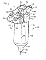
- FIG. 1 Reference is next made to Figure 2 to describe the main features of the flask assembly 48 as it would appear in a sterile condition ready for placement in the cabinet 21 ( Figure 1).
- the flask assembly 48 will be supplied in a sterile container which will also include most of the items needed for the procedure. These will include needles, tubing, gauze etc. as is commonly done in medical procedures requiring sterile items for the procedure.
- the assembly 48 is made up of two main parts, namely the flask 56 and a connector assembly 62 which serves to carry components used in the treatment procedure.
- the assembly 48 is shown as it would be placed in the cabinet 21 ( Figure 1), with the input syringe 50 and output syringe 52 mounted side-by-side on the connector assembly 62.
- the assembly 62 is shown from the back as opposed to from the front in Figure 1.
- the connector assembly includes an overhanging portion 64 which will meet parts of the apparatus contained in the cabinet 21 when the flask assembly 48 is lowered downwardly into the cabinet 21.
- electrical and gas connections are made automatically when the assembly 48 moves into its final position in the cabinet 21.
- the overhanging portion 64 provides clearance under the portion 64 to allow the inlet tubing 54 to be fed from the input syringe 50 to a supply probe 65 ( Figures 3 and 4).
- the syringes 50 and 52 are conveniently stored on the connector assembly 62 between a central shaped mound 66 ( Figure 1) and respective locators 68 and 70 which are sufficiently flexible to allow the syringes to be engaged and held in place. Further location is provided by respective channel portions 72, 74 which receive respective flanges 76, 78 on the syringes 50 and 52. This interengagement locates the syringes 50, 52 longitudinally but does not interfere with vertical removal of the syringes 50, 52.
- the flask assembly 48 is located in the cabinet 21 by a shelf 80 having an opening 81 for the flask 56, and below the shelf, a locator 82 having an opening 84 which is also proportioned to receive the flask 56 loosely.
- the connector assembly 62 rests on the shelf 80 about the opening 84 to locate the flask assembly 48 vertically and in proper relationship with two of the stressors to which the charge is to be subjected.
- One of these stressors is heat supplied by an infrared (IR) heater 86, another is ultraviolet (UV) light provided by an UV radiator 88 positioned about the flask 52.
- IR infrared
- UV ultraviolet
- the overhanging portion 64 of the connector assembly 62 brings electrical connectors and gas supply connections together as will be explained after describing Figure 4.
- Figure 3 also shows the shape of the flask 56. It extends about a longitudinal axis 89 and has a generally cylindrical main portion 90. A transitional portion 92 extends from the portion 90 to a cup 94 proportioned to receive about 12 ccs of charge from the input syringe 50 ( Figure 1).
- the supply probe 65 will be described more fully with reference to Figure 5. For the moment it is sufficient to understand that the function of the probe 65 is to supply charge to and remove conditioned charge from the flask 56. Also, a mixture of ozone and oxygen is fed through a lumen in the probe 65 and a temperature sensor is provided in the probe 65. Heat from the IR heater 86 causes the charge to heat and that together with the gas supply, causes the charge to bubble and fill the flask 56. The large surface area so formed is then subject to UV light from the radiator 88. These stressors are used to condition the charge before it is delivered by the apparatus to the output syringe 52, ( Figure 1).
- the probe 65 is located centrally in the cup 94 by a solid extension 96 at the end of the probe 65.
- the extension fits closely inside a cylindrical socket 98 formed in the bottom of the flask 58, and extending from the cup 94.
- the extension 96 is placed in the socket 98 during assembly and the socket is crimped from the outside to retain the extension 96 in the socket 98 and to thereby secure the supply probe 65 in the flask 56.
- the flask 56 is essentially an envelope made by blow moulding a parazon of low density polyethylene (LDPE) and has an internal volume that is about 70 times that of the charge.
- LDPE low density polyethylene
- the walls are translucent to allow penetration of the UV light stressor.
- Figure 4 is an exploded view of the flask assembly 48 with the syringes 50 and 52 included.
- This assembly includes parts of several systems. Firstly an input system made of parts associated with receiving a charge and placing it in the flask 56 ready for conditioning it. Next, an output system is made up of parts related to extracting the conditioned charge from the flask 56, and lastly, parts related to gas supply and recovery system.
- the charge is received in the input syringe 50 which is connected by the thermoplastic tubing 54 to an elbow 102 forming part of the probe 65.
- This elbow leads to an intake lumen 104 formed in an extruded main body 106 which can be seen in the cross-sectional view, Figure 5. This view is taken on line 5-5 of Figure 4.
- the intake lumen 104 extends to a leading end 108 of the probe adjacent the extension 96. Consequently, the charge can be fed into the cup 94 of the flask 56 by actuating the syringe 50 to move the charge through the inlet tubing 54, through the elbow 102, and then via the lumen 104 into the cup 94.
- the second set of parts is related to removing the conditioned charge.
- the syringe 52 is the prime mover so that when it is actuated, the charge is drawn from the cup 94 into a return lumen 109 at the end 108 of the probe 65. The charge then passes through the lumen 109 leaving via an elbow 110 which in turn leads to outlet tubing 58 and to the syringe 52.
- the third set of parts mentioned above relate to a gas supply and recovery system that creates ozone from oxygen and supplies and removes an ozone/oxygen mixture.
- Oxygen from a replaceable oxygen supply cartridge 114 passes through an ozone generator (not shown) built into the cabinet 21 ( Figure 1). Connections to the flask assembly 48 are made automatically when the assembly 48 is lowered into the cabinet as described previously.
- a pair of nipples 116 engage in suitable receptors (not shown) in the cabinet.
- the nipple that can be seen in Figure 4 is connected to gas exhaust tubing 118 which leads to an in-line filter 120 having fittings for sealably connecting to a cup 122 formed in a top 124 of the flask 56.
- the exhaust gas from the process is carried by these parts to an exhaust system as is conventional when using ozone.
- the connector assembly 62 includes a moulded platform 126 shaped to carry the various components. As indicated in Figure 4, the outlet filter 120 is normally mounted in a holder 128 shaped to receive the disk-shaped filter 120.
- the connection to the gas supply is made using the hidden nipple 116 which supplies gas to a gas inlet tubing 130.
- the tubing 130 directs gas to an in-line filter 132 which is associated with standard connections to send the gas to a gas supply tubing 134.
- the filter 132 is arranged to engage in a support 137 formed in the platform 126, and an elbow 135 on the probe 65 is connected to the tubing 134 to lead the gas to a gas lumen 136 in the extruded probe main body 106.
- This lumen like the intake lumen 104 and return lumen 109, leads to the end 108 of the main body which will be submerged in charge when the charge is entered through the lumen 104.
- the probe 65 also locates a temperature sensor 138 exposed near the end 108 through a side opening 140 cut into the side of the main body 106.
- a sterile sleeve 142 of very thin filmic plastics material encloses the sensor, but because the sleeve 142 is thin, there is a rapid temperature transfer to allow the sensor 138 to respond quickly to changes in temperature.
- the sensor 138 is connected by two wires in the form of a conductive ribbon 144 which extends through a larger lumen 146 (Figure 5) in the probe 46, and then to a connector 148 mounted on the platform 126.
- This connector 148 is adapted to engage a corresponding sliding connector 150 ( Figure 3) mounted in the shelf 80 of the cabinet 21.
- the connector 150 cooperates with the connector 148 to connect the temperature sensor 138 to a control system indicated generally at 151 in Figure 1 and contained in the cabinet 21 ( Figure 1).
- the connectors 148,150 to the temperature sensor 138 preferably include a 4-point electrical connection (two connections to each contact) to ensure that electrical connections to the sensor 138 are made securely, and to permit the detection of a bad connection.
- the assembled supply probe 65 is passed through a receiver 152 formed in the top 124 of the flask 56, and the extension 96 at the leading end of the probe 65 is manoeuvred into the socket 98 under the cup 94 of the flask 56.
- the socket 98 is then crimped from the outside sufficiently to positively locate the extension, and hence the probe, relative to the flask 56.
- a seal 154 under a collar 156 on the outer end of the main body 106 is brought to bear against the receiver 152 and held in compression while the socket 98 is crimped. As a result the probe is sealed in the flask with a gas tight seal.
- the platform 126 and the parts mounted on the platform are attached to a cover 158. This is done by the use of two self-tapping screws 160 (one of which is shown) which pass through openings 162 and engage in respective bosses 164 formed in the platform 126.
- the sub-assembly of the platform 126 and the cover 158 is then attached to the flask 56 using snap-fitting structure 166 formed on the flask 56 and on the cover 158.
- This structure is discontinuous around the flask so that there is only one way to attach the sub-assembly to the flask 56 thereby ensuring that the parts line up correctly to engage the cup 122 on the flask 56 and to provide the necessary clearance under the overhanging portion 64 of the connector assembly 62 for the various tubing, gas connections and electrical connections.
- the flask assembly 48 then receives the syringe locators 68 and 70 which snap into respective slots 168, 170 formed in the top of the cover 158.
- the outlet tubing 58 is then fed through an opening 172 at the back of the cover 158 and attached to the syringe 52.
- the inlet tubing 54 is attached to the syringe 50 and the syringes are engaged on the cover 158 to be held in place (as previously described) by the combinations of the mound 66 with the respective locators 68 and 70.
- the completed flask assembly 48 is sterilized and packaged for use as mentioned earlier.
- the process in general is designed to source suitable mammalian blood either by using compatible blood or by using blood taken from a patient who is to receive the treated blood. This process will be described for the latter case but is not to be limited to that case.
- the apparatus must be readied for use by placing the operator's smart card in the slot 40.
- the operator's smart card may only be effective if used in conjunction with a personal identification number (PIN) input via the GDT 46.
- PIN personal identification number
- a patient's smart card, which may be included with the package containing the flask assembly 48, is given to the patient for the patient to place the card in the slot 38.
- the GDT 46 then proceeds to present instruction, error messages, and comments as the procedure progresses.
- the input syringe 50 is lifted from its position on the connector assembly 62 and placed conveniently with the inlet tubing 54 passing through a heat sealer 174 which is attached to the cabinet 21 for use to seal and sever the inlet tubing 54 as will be explained.
- the inlet tubing 54 has a locator 176 mounted on the tubing to position the inlet tubing 54 in the sealer 174.
- the output syringe 52 is then removed in similar fashion and placed vertically as shown in Figure 1.
- the syringe 52 is located in a fixed mount 178 using the flange 78 and a syringe operator 180 extends downwardly and is engaged in an actuator 182 which can be driven along a slide 184 by a motor and drive (not shown) in the cabinet.
- the actuator 182 that receives the syringe operator 180 is intentionally oversized in the vertical dimension to allow easy installation of the output syringe 52 and removal of the output syringe 52 without affecting the position of the syringe operator 180 relative to the body of the output syringe 52. This operation will be described with reference to removing a conditioned charge.
- the outlet tubing 58 associated with the syringe 52 is led through a second heat sealer 186, and a locator 188 on the tubing 58 positions the outlet tubing in the sealer 186.
- This sealer 186 will be used after the conditioned charge is drawn into the syringe 52, as will be explained.
- the heat seal locators 176,188 allow the user to accurately and repeatably position the thermoplastic tubing 54,58 for proper automatic sealing and severing.
- the locators 176,188 thus ensure that the tubes 54,58 are not misaligned or inserted improperly in the sealers 174,186, and allow the control system to detect that the tubing 54,58 is properly placed.
- the locators 176,188 minimize the likelihood that tubing 54,58 will get caught in the door by controlling the length and positioning of tubing inside the cabinet.
- the locators 176,188 consist of two pieces of metal film positioned in an opposing orientation along each side of the tube. The metal film advantageously allows quick sealing of the tubes 54,58 and the prevention of contamination. It is to be appreciated, however, that other tube locator constructions are also possible.
- a message on the GDT 46 ( Figure 1) reminds the operator to close the door 26 and the door lock bar 34 is engaged.
- the control system 151 Figure 1) activates the door so that the cabinet can be opened only by using the two smart cards. Consequently the smart card carried by the patient is necessary so that no one other than the patient can cooperate with the operator to get into the cabinet 21.
- the patient's smart card is preferably attached to the patient's wrist in a semi-permanent fashion using a suitable band of the type commonly used in hospitals.
- a T-connector 190 includes a valve controlled by a selector 192 which connects the body of the syringe to either an in-line port 194, or a side port 196 at right angles to the axis of the body.
- the inlet tubing 54 is attached to the port 196 and the port 194 is available.
- a needle (not shown) is attached to port 194 and about 2 ccs of an anti coagulant (preferably sodium citrate) is drawn into the syringe.
- the needle is discarded into a sharps container and then a tubing assembly 198 ( Figure 1) is attached to the in-line port 194.
- This assembly 198 includes a one-way valve 200, to avoid back flow, and at its leading end an angel wing collector set 202 is ready for engagement into the patient to collect blood.
- the collector set is used to draw 10 ccs of blood into the syringe 50 where it is mixed with the sodium citrate by rocking the syringe gently to create a blood charge for treatment in the process according to the invention.
- the selector 192 on the T-connector 190 is operated to connect the body of the syringe 50 with the side port 196 leaving the tubing assembly attached but inoperable.
- the syringe 50 is then inverted (i.e. placed with the T-connector uppermost) and about 3 to 4 ccs of sterile air are drawn from the flask 56 into the syringe.
- the syringe 50 is then again inverted so that the air is above the charge and the syringe is then operated to drive the charge through the inlet tubing 54 and into the flask 56 driven by the air in the syringe.
- the inlet tubing is cleaned out as the air follows the charge.
- the syringe 50 has to be separated from the cabinet 21 to which it is connected by the inlet tubing 54. This is achieved by operating the heat sealer 186 which seals and severs the tubing under the influence of heat.
- the control system 151 in the cabinet 21 takes over and starts the IR heater 86 ( Figure 3) to elevate the temperature of the charge.
- This is one example of a process known generally as "stressing" the charge and the IR radiator is known as a “stressor”.
- the temperature is elevated to about 42.5°C and is controlled from a reading originating with the temperature sensor 138.
- the control system activates a second stressor.
- An ozone generator sends an oxygen/ozone mixture into the flask 56 through the probe 65 as described earlier.
- the UV light source 88 (third stressor) is activated so that the heated charge is simultaneously stressed by the ozone/oxygen mixture and by the UV light simultaneously for about 3 minutes.
- the bubbled charge fills the flask and is then allowed to settle and cool for about 7 minutes so that bubbles in the charge will tend to settle.
- the GDT 46 ( Figure 1) will respond to the control system to give the operator a message that the smart cards will be needed to withdraw the conditioned charge.
- the door 26 ( Figure 1) will not open until the charge is available in the output syringe 52 even if the cards are inserted at this stage.
- the door 26 will remain dosed unless the cards are inserted.
- the apparatus will commence the step of moving the charge from the flask 56 (Figure 3) to the output syringe 52 ( Figure 1). This is done automatically by the actuator 182 seen in Figure 1, which draws the operator 180 downwardly.
- a knocker 204 is then driven to tap the syringe at a rate of about 1 Hertz to break any resident bubbles.
- the knocker consists of an impact tool 205 mounted in the recess 30 of the cabinet, and driven to strike the syringe 52 gently thereby deflecting the syringe sideways to store energy in a coil spring 207 positioned on the opposite side of the syringe from the tool 205.
- the energy in the spring then causes the spring to rebound thereby pushing the syringe back into contact with the impact tool 305 ready for the next impact.
- the frequency can be varied and will to some extent depend on the geometry and mass of the parts. However, it has been found that a frequency of 1 Hertz with a spring having a spring rate of between about 0.1 to 5N° provides good results.
- the actuator 182 and bubble detector are operated to express some of the contents of the syringe 52 back into the outlet tubing 58 until there remains a volume of 9 to 10 ccs of conditioned charge. If following the operation of the actuator 182, there are still bubbles in the syringe 52 after the knocking process, the control system will detect this, via the bubble detector, and repeat the knocking process until the bubbles are gone, with the bubbles removed in a closed loop.
- a sensor (not shown) in the heat sealer 186 tells the control system in the cabinet 21 that the system is ready to seal the outlet tubing 58 in similar fashion to the seal made on the inlet tubing 54 as previously described.
- the actuator 182 into which the plunger end of the operator 180 is inserted has been designed to be intentionally wide in the vertical direction. This configuration allows the user to easily insert the plunger end of the operator 180, but, more importantly, it allows the user to remove the syringe 52 without affecting the operator 180. This ensures that no undue force will be exerted on the operator 180 which could result in the operator 180 moving and causing a leak of blood.
- the process has now reached a critical point. If the patient has not inserted the patient's smart card by now, the apparatus will wait only for a predetermined time (usually about 20 minutes) before aborting the process. If the process is to be aborted, a message will appear on the GDT 46 ( Figure 1) and the control system will cause the actuator 180 to drive the syringe operator 182 so that the conditioned charge is returned to the flask 56 before shutting down the process. Once this is done the operator can open the door 26 using only the operator's card so that the flask 56 and its contents can be discarded to ready the apparatus 20 for a new process.
- the sealing sealer 186 is a heat sealer which will seal and sever the tubing 58, the door 26 will open, and the output syringe 52 is then available for removal from the cabinet 21.
- the patient must be prepared for the injection of about 8 to 9 ccs of conditioned charge. Normally [local anaesthetic is optional], the patient will be anaesthetized in the gluteal muscles using a suitable needle and performing the standard procedure for ensuring that the needle has not been inserted into a blood vessel. Next, the anaesthetic syringe is removed and the needle is left in the patient.
- the output syringe 52 is then taken to the anaesthetic needle and after discarding the remaining tubing 58 from the heat sealing operation, the output syringe 52 is attached to the anaesthetic needle and the conditioned charge is fed into the patient slowly. After this procedure, the output syringe and attached needle are discarded.
- the apparatus can then be prepared for the next procedure by removing the remains of the flask assembly 48.
- the process can be used to treat mammalian blood in a blood charge to provide a conditioned charge for giving to a patient in a medical procedure.
- the process includes the steps of providing an automatic apparatus for treating the blood charge to create the conditioned charge, and for presenting the conditioned charge ready for use.
- the apparatus has a secure environment, a door controlling access to the environment, a flask, and stressors arranged to operate on a charge in the flask in the controlled environment.
- the blood charge is transported into the secure environment through thermoplastic inlet tubing for deposit in the flask, and the tubing is then sealed and severed.
- the part of the inlet tubing outside the secure environment is removed and the operation of the automatic apparatus is initiated so that the stressors will operate on the charge for a predetermined period, thereby stressing the charge in the flask while maintaining the secure environment.
- the apparatus is then given time to transport the conditioned charge from the flask to a receiver, and the door is opened to provide access to the receiver for use to give the conditioned charge to the patient.
- Improved control can be provided by the preferred use of smart cards, as explained, and by the use of thermoplastic tubing and heat sealers to ensure that the secure environment is maintained. Also, the process can be enhanced by use of the knocker to reduce the time needed to dissipate the bubbles in the conditioned charge.
- the invention claimed is useful in practicing procedures in which mammalian blood is to be conditioned for subsequently giving to a patient for treating or preventing various medical conditions.
Abstract
Description
Claims (28)
- Apparatus (20) for conditioning mammalian blood for subsequent use in a medical procedure, the apparatus including:a cabinet (21) having a secure environment and a door (26) providing the only access to the secure environment;an input system (50, 54) for transporting a blood charge from a source to the cabinet;a flask (56) removably contained in said secure environment and coupled to the input system (50, 54) to receive said charge;stressors (86, 88, 114) coupled to the cabinet and positioned for operation to create a conditioned charge in the flask, said stressors comprising an oxygen source (114) removably coupled to the cabinet (21) and an ozone generator coupled to the oxygen source to generate an ozone/oxygen mixture for delivery to the flask (56);an output system (52, 58) coupled to the flask (56) and including a receiver (52) for the conditioned charge; anda control system (151) contained in the cabinet (21) and operable upon closing the door (26) to lock the door and to then automatically condition the charge and to cause the charge to move from the flask (56) to the receiver (52), whereby a charge from the input system (50, 54) is conditioned and delivered to the receiver, the door is then unlocked and the conditioned charge is ready to be removed and used to complete the medical procedure.
- Apparatus as claimed in claim 1 in which the input system includes an input syringe (50) operable to draw blood to form at least part of said charge, and input tubing (54) connecting the input syringe to the flask (56) to transport the charge into the flask.
- Apparatus as claimed in claim 2 in which the input tubing (54) is thermoplastic tubing, and in which the cabinet (21) includes a first heat sealer (174) operable to seal and sever the input tubing, whereby the input syringe (50) can be separated from the cabinet and flask (56) for subsequent disposal.
- Apparatus as claimed in claim 2 or claim 3 in which the input syringe (50) includes a valved T-connector (190) having first and second ports (194, 196) so that the first port is available to draw the charge and the second port is attached to the input tubing (54) for use to transport the charge to the flask (56).
- Apparatus as claimed in any one of the preceding claims in which the flask (56) has an internal volume significantly greater than the volume of the charge to permit the charge to bubble thereby increasing the surface area available for the stressors (86, 88, 114) to condition the charge.
- Apparatus as claimed in any one of claims 1 to 4 in which the flask (56) includes a main portion (90) defining an internal volume to receive the charge and a connector assembly (62) coupled to the main portion.
- Apparatus as claimed in claim 6 and further including a probe (65) coupled to the connector assembly (62) and contained in the main portion (90), the probe extending to a leading end and having an input lumen (104) coupled to the input system to deliver the charge into the internal volume and an output lumen (109) coupled to the output system for delivering the conditioned charge to the output system.
- Apparatus as claimed in claim 7 in which the probe (65) further includes a gas lumen (136) coupled to one of said stressors (86, 88,114) for delivering a gas stressor to the charge to cause the charge to bubble.
- Apparatus as claimed in claim 7 or claim 8 in which the probe (65) further includes a further lumen (146) and a temperature sensor (138) positioned in the further lumen for monitoring the temperature of the charge.
- Apparatus as claimed in claim 9 in which said further lumen (146) ends adjacent said leading end at a side opening (140) and in which the temperature sensor (138) terminates in the side opening for better thermal contact with the charge.
- Apparatus as claimed in claim 9 or claim 10 and further including a filmic sleeve (142) surrounding the temperature sensor (138) to avoid contact between the sensor and the charge.
- Apparatus as claimed in any one of claims 9 to 11 in which the probe (65) further includes an extension (96) engaged in said further lumen (146) at the leading end of the probe and extending downwardly, and in which the flask (56) includes a socket (98) at the bottom of the main portion (90) and extending downwardly to accommodate at least part of said extension to locate the probe in the main portion of the flask.
- Apparatus as claimed in claim 12 in which the socket (98) is crimped to hold the extension (96) in the socket.
- Apparatus as claimed in any one of claims 7 to 13 in which the lumens (104, 109, 146) extend to the leading end.
- Apparatus as claimed in any one of the preceding claims in which said stressors further comprise an infrared source (86) positioned in the cabinet (21) under the flask (56) for radiating the charge to heat the charge in the flask.
- Apparatus as claimed in any one of the preceding claims in which said stressors further comprise an ultraviolet source (88) positioned in the cabinet (21) for subjecting the charge to ultraviolet light to stress the charge in the flask (56).
- Apparatus as claimed in any one of the preceding claims in which the cabinet (21) includes a cavity (81) for receiving the flask in a downward movement, the cavity being positioned to locate the flask in relation to the stressors (104, 109, 146).
- Apparatus as claimed in any one of the preceding claims in which the cabinet (21) includes a front recess (30), and a top depression (32) above the recess, the door (26) being shaped to cover both the front recess and the depression when the door is in the closed position.
- Apparatus as claimed in any one of the preceding claims in which the receiver is an output syringe (28).
- Apparatus as claimed in claim 19 and further including an actuator (182) attached to the cabinet (21) and positioned to operate the output syringe (28) as directed by the control system (151) to first draw the conditioned charge from the flask (56) and to then be used to inject the charge into the patient.
- Apparatus as claimed in claim 19 or 20 and further including thermoplastic output tubing (58) connecting the flask (56) to the output syringe (52) to transport the conditioned charge to the output syringe.
- Apparatus as claimed in claim 21 and further including a second heat sealer (186) attached to the cabinet (21) and positioned to be operated by the control system (151) to seal and sever the output tubing (58) between the flask (56) and the output syringe (52).
- Apparatus as claimed in any one of claims 19 to 22 and further including a knocker (204) attached to the cabinet (21) and positioned to rap the output syringe (52) to dissipate any bubbles in the conditioned charge contained by the output syringe.
- Apparatus as claimed in any one of the preceding claims in which the control system (151) includes an identification system (37) for recognising a first identifier carried by the operator, and a second identifier carried by the patient, the identification system being adapted to recognise and to then permit the operator to operate the apparatus.
- Apparatus as claimed in any one of claims 1 to 23 and further including an operator card reader (40) for reading discrete information on a card used to identify the operator of the apparatus (20) to prevent unauthorized use.
- Apparatus as claimed in claim 25 and further including a patient card reader (38) for reading discrete information on a patient card used to identify the patient so that the patient can be identified by presentation of the patient card to the patient card reader.
- Apparatus as claimed in any one of the preceding claims and further including a printer (42, 44) for providing a printout of data relating to the procedure for an individual patient.
- Apparatus as claimed in any one of the preceding claims in which the control system includes a graphic display interface (46) for the operator.
Applications Claiming Priority (3)
| Application Number | Priority Date | Filing Date | Title |
|---|---|---|---|
| US15421599P | 1999-09-16 | 1999-09-16 | |
| US154215P | 1999-09-16 | ||
| PCT/CA2000/001078 WO2001019318A1 (en) | 1999-09-16 | 2000-09-15 | Apparatus and process for conditioning mammalian blood |
Publications (2)
| Publication Number | Publication Date |
|---|---|
| EP1214037A1 EP1214037A1 (en) | 2002-06-19 |
| EP1214037B1 true EP1214037B1 (en) | 2004-04-07 |
Family
ID=22550473
Family Applications (1)
| Application Number | Title | Priority Date | Filing Date |
|---|---|---|---|
| EP00962115A Expired - Lifetime EP1214037B1 (en) | 1999-09-16 | 2000-09-15 | Apparatus for conditioning mammalian blood |
Country Status (14)
| Country | Link |
|---|---|
| US (4) | US6736788B1 (en) |
| EP (1) | EP1214037B1 (en) |
| JP (1) | JP2003509124A (en) |
| AT (1) | ATE263540T1 (en) |
| AU (1) | AU776660B2 (en) |
| CA (1) | CA2381730A1 (en) |
| DE (1) | DE60009724T2 (en) |
| DK (1) | DK1214037T3 (en) |
| ES (1) | ES2214314T3 (en) |
| IL (1) | IL148636A (en) |
| NZ (1) | NZ517806A (en) |
| PT (1) | PT1214037E (en) |
| WO (1) | WO2001019318A1 (en) |
| ZA (1) | ZA200202085B (en) |
Families Citing this family (31)
| Publication number | Priority date | Publication date | Assignee | Title |
|---|---|---|---|---|
| AU6683498A (en) * | 1997-03-03 | 1998-09-22 | Medical Solutions, Inc. | Method and apparatus for pressure infusion and temperature control of infused liquids |
| US7090658B2 (en) * | 1997-03-03 | 2006-08-15 | Medical Solutions, Inc. | Temperature sensing device for selectively measuring temperature at desired locations along an intravenous fluid line |
| US7041941B2 (en) * | 1997-04-07 | 2006-05-09 | Patented Medical Solutions, Llc | Medical item thermal treatment systems and method of monitoring medical items for compliance with prescribed requirements |
| US6467953B1 (en) | 1999-03-30 | 2002-10-22 | Medical Solutions, Inc. | Method and apparatus for monitoring temperature of intravenously delivered fluids and other medical items |
| US6719715B2 (en) | 1999-09-16 | 2004-04-13 | Vasogen Ireland Limited | Apparatus and process for conditioning organic fluid |
| US6802892B2 (en) * | 1999-09-16 | 2004-10-12 | Vasogen Ireland Limited | Apparatus and process for conditioning organic fluid |
| US7238171B2 (en) * | 2001-03-12 | 2007-07-03 | Medical Solutions, Inc. | Method and apparatus for controlling pressurized infusion and temperature of infused liquids |
| US8226605B2 (en) | 2001-12-17 | 2012-07-24 | Medical Solutions, Inc. | Method and apparatus for heating solutions within intravenous lines to desired temperatures during infusion |
| NZ540349A (en) * | 2002-11-26 | 2007-04-27 | Vasogen Ireland Ltd | Medical treatment control system |
| US20050154368A1 (en) * | 2003-11-21 | 2005-07-14 | Vasogen Ireland Limited | Medical material handling systems |
| US7611504B1 (en) | 2004-03-09 | 2009-11-03 | Patented Medical Solutions Llc | Method and apparatus for facilitating injection of medication into an intravenous fluid line while maintaining sterility of infused fluids |
| CN103381277B (en) | 2005-04-21 | 2015-11-25 | 联邦高等教育系统匹兹堡大学 | Paracorporeal respiratory assist lung |
| US20060270997A1 (en) * | 2005-05-19 | 2006-11-30 | Vasogen Ireland Limited | Permission-based material dispenser |
| US20060264778A1 (en) * | 2005-05-19 | 2006-11-23 | Vasogen Ireland Limited | Verification method and system for medical treatment |
| US7740611B2 (en) * | 2005-10-27 | 2010-06-22 | Patented Medical Solutions, Llc | Method and apparatus to indicate prior use of a medical item |
| US8487738B2 (en) * | 2006-03-20 | 2013-07-16 | Medical Solutions, Inc. | Method and apparatus for securely storing medical items within a thermal treatment system |
| US8226293B2 (en) * | 2007-02-22 | 2012-07-24 | Medical Solutions, Inc. | Method and apparatus for measurement and control of temperature for infused liquids |
| US8961471B2 (en) * | 2007-12-12 | 2015-02-24 | Minimus Spine, Inc. | Syringe device, system and method for delivering ozone gas |
| US8425487B2 (en) | 2009-07-01 | 2013-04-23 | Fresenius Medical Care Holdings, Inc. | Drug vial spikes, fluid line sets, and related systems |
| DE102010008479A1 (en) * | 2010-02-18 | 2011-08-18 | Fresenius Medical Care Deutschland GmbH, 61352 | A method of handling patient data, medical treatment device and computer readable storage medium |
| MX356030B (en) | 2011-01-31 | 2018-05-09 | Fresenius Medical Care Holdings Inc | Preventing over-delivery of drug. |
| WO2012108984A1 (en) | 2011-02-08 | 2012-08-16 | Fresenius Medical Care Holdings, Inc. | Magnetic sensors and related systems and methods |
| ITMI20111439A1 (en) * | 2011-07-29 | 2013-01-30 | Paolo Benatti | APPARATUS FOR THE OZONIZATION OF BIOLOGICAL FLUIDS, PARTICULARLY FOR BLOOD. |
| US9211381B2 (en) | 2012-01-20 | 2015-12-15 | Medical Solutions, Inc. | Method and apparatus for controlling temperature of medical liquids |
| US9144646B2 (en) | 2012-04-25 | 2015-09-29 | Fresenius Medical Care Holdings, Inc. | Vial spiking devices and related assemblies and methods |
| WO2014126964A1 (en) | 2013-02-15 | 2014-08-21 | Medical Solutions, Inc. | Plural medical item warming system and method for warming a plurality of medical items to desired temperatures |
| EP3220298A1 (en) | 2016-03-14 | 2017-09-20 | Fenwal, Inc. | Cell processing system and method with process parameter control |
| EP3249563B1 (en) | 2016-05-27 | 2021-08-11 | Fenwal, Inc. | Cell processing system and method with preliminary process evaluation |
| US10654000B2 (en) | 2016-07-13 | 2020-05-19 | Fenwal, Inc. | Cell processing system and method with centralized data management, monitoring and/or control |
| FR3066381B1 (en) * | 2017-05-16 | 2019-06-28 | Robocath | PROTECTIVE ENVELOPE FOR A ROBOTIC MODULE FOR DRIVING AN ELONGATED MEDICAL DEVICE WITH A GUIDE TRACK |
| CN109824170B (en) * | 2019-03-12 | 2021-07-06 | 四川国润和洁环境科技有限公司 | Domestic sewage treatment device |
Family Cites Families (41)
| Publication number | Priority date | Publication date | Assignee | Title |
|---|---|---|---|---|
| DE1068428C2 (en) | 1957-05-21 | 1960-04-21 | Hermann Dr Med Jentjens | Process and device for the production of oxygenated blood |
| CH456885A (en) | 1967-10-20 | 1968-05-31 | Nestle Sa | Apparatus for the preparation of infant foods |
| US3946731A (en) * | 1971-01-20 | 1976-03-30 | Lichtenstein Eric Stefan | Apparatus for extracorporeal treatment of blood |
| IE40006B1 (en) * | 1973-09-07 | 1979-02-14 | Lichtenstein Eric Stefan | Automated apparatus for monitoring of physiological parameters and control of fluid therapy including extracorporealcirculation of blood |
| DE2456932A1 (en) | 1974-12-02 | 1976-06-10 | Gebhard Roggors | Magnetic field oxygenation enclosure - for gas exchange between blood and a gas atmosphere in a magnetic field |
| US4585441A (en) * | 1984-09-17 | 1986-04-29 | Minnesota Mining And Manufacturing Company | IV fluid control system with fluid runaway prevention |
| US4578056A (en) * | 1984-10-29 | 1986-03-25 | Extracorporeal Medical Specialties, Inc. | Patient photopheresis treatment apparatus and method |
| US4596547A (en) * | 1984-10-29 | 1986-06-24 | Mcneilab, Inc. | Valve apparatus for photoactivation patient treatment system |
| DE8704467U1 (en) | 1987-01-15 | 1988-05-26 | Quarzlampenfabrik Dr.-Ing. Felix W. Mueller Gmbh & Co Kg, 4300 Essen, De | |
| US4878891A (en) * | 1987-06-25 | 1989-11-07 | Baylor Research Foundation | Method for eradicating infectious biological contaminants in body tissues |
| EP0339924B1 (en) * | 1988-04-29 | 1995-03-29 | Medizone International, Inc. | Apparatus for the controlled generation and administration of ozone |
| US5104373A (en) * | 1988-09-22 | 1992-04-14 | American Immuno Tech, Inc. | Method and apparatus for extracorporeal blood treatment |
| US5037390A (en) * | 1989-12-28 | 1991-08-06 | Kenneth Raines | System and method for mixing parenteral nutrition solutions |
| US5254080A (en) * | 1990-03-14 | 1993-10-19 | Minnesota Mining And Manufacturing Company | Quick-changeover apparatus for handling medical fluid |
| US5935092A (en) * | 1990-12-20 | 1999-08-10 | Baxter International Inc. | Systems and methods for removing free and entrained contaminants in plasma |
| US5591457A (en) | 1992-02-07 | 1997-01-07 | Vasogen Inc | Method of inhibiting the aggregation of blood platelets and stimulating the immune systems of a human |
| US5980954A (en) | 1992-02-07 | 1999-11-09 | Vasogen Ireland Limited | Treatment of autoimmune diseases |
| DE69332087T2 (en) * | 1992-02-07 | 2002-10-24 | Inc Etobicocke Vasogen | METHOD FOR INCREASING THE NITROGEN OXIDE CONCENTRATION IN BLOOD |
| US5354000A (en) * | 1992-05-05 | 1994-10-11 | Glenn Albert Wright | Sharps disposal system |
| DE4323295C1 (en) | 1993-07-12 | 1995-02-09 | Manfred R Dr Hamm | Dosing device |
| US5466229A (en) * | 1993-08-06 | 1995-11-14 | Davstar, Inc. | Fluid collection system |
| US5746708A (en) * | 1993-12-22 | 1998-05-05 | Baxter International Inc. | Peristaltic pump tube holder with pump tube shield and cover |
| JP3364311B2 (en) * | 1994-03-15 | 2003-01-08 | シスメックス株式会社 | Quantitation device |
| US5713856A (en) * | 1995-03-13 | 1998-02-03 | Alaris Medical Systems, Inc. | Modular patient care system |
| DK0768886T3 (en) * | 1995-05-05 | 2003-12-01 | Vasogen Ireland Ltd | Endothelial lining effects and treatment of vasospastic disorders |
| US5540898A (en) | 1995-05-26 | 1996-07-30 | Vasogen Inc. | Ozone generator with in-line ozone sensor |
| US5628727A (en) * | 1995-08-15 | 1997-05-13 | Hakky; Said I. | Extracorporeal virioncidal apparatus |
| US6146354A (en) * | 1996-05-24 | 2000-11-14 | Horizon Medical Products | Asymmetrical multi-lumen apheresis catheter with balanced flow rates |
| WO1998001760A2 (en) * | 1996-07-05 | 1998-01-15 | Beckman Coulter, Inc. | Automated sample processing system |
| US5687717A (en) * | 1996-08-06 | 1997-11-18 | Tremont Medical, Inc. | Patient monitoring system with chassis mounted or remotely operable modules and portable computer |
| US5800721A (en) * | 1996-08-30 | 1998-09-01 | Baxter International Inc. | Combined cardiotomy fluid and venous blood reservoir |
| US6190609B1 (en) * | 1996-11-19 | 2001-02-20 | Baxter International Inc. | Methods and apparatus for inactivating contaminants in biological fluid |
| US6268119B1 (en) * | 1997-01-24 | 2001-07-31 | Asahi Medical Co., Ltd. | Method for separating cells |
| US6544162B1 (en) * | 1997-04-25 | 2003-04-08 | Washington State University Research Foundation | Semi-continuous, small volume centrifugal blood separator and method of using therefor |
| US5893838A (en) * | 1997-08-15 | 1999-04-13 | Therox, Inc. | System and method for high pressure delivery of gas-supersaturated fluids |
| AU741181B2 (en) * | 1997-09-12 | 2001-11-22 | Centre De Recherche Du Centre Hospitalier De L'universite De Montreal | Treatment of stress and preconditioning against stress |
| FR2786876B1 (en) * | 1998-12-03 | 2001-08-31 | Nicolas Bara | REFRIGERATED ENCLOSURE FOR STORING ARTICLES PROVIDED WITH MEANS FOR CONTROLLING THE CONTENT OF THE SPEAKER |
| US6113566A (en) * | 1998-12-15 | 2000-09-05 | Foundation For Blood Irradiation Inc. | Ultraviolet blood irradiation method and apparatus |
| US6719715B2 (en) * | 1999-09-16 | 2004-04-13 | Vasogen Ireland Limited | Apparatus and process for conditioning organic fluid |
| US6802892B2 (en) * | 1999-09-16 | 2004-10-12 | Vasogen Ireland Limited | Apparatus and process for conditioning organic fluid |
| US6613280B2 (en) * | 2001-03-20 | 2003-09-02 | Therox, Inc. | Disposable cartridge for producing gas-enriched fluids |
-
2000
- 2000-09-15 JP JP2001522956A patent/JP2003509124A/en active Pending
- 2000-09-15 IL IL148636A patent/IL148636A/en not_active IP Right Cessation
- 2000-09-15 DE DE60009724T patent/DE60009724T2/en not_active Expired - Fee Related
- 2000-09-15 NZ NZ517806A patent/NZ517806A/en unknown
- 2000-09-15 EP EP00962115A patent/EP1214037B1/en not_active Expired - Lifetime
- 2000-09-15 ES ES00962115T patent/ES2214314T3/en not_active Expired - Lifetime
- 2000-09-15 AT AT00962115T patent/ATE263540T1/en not_active IP Right Cessation
- 2000-09-15 WO PCT/CA2000/001078 patent/WO2001019318A1/en active IP Right Grant
- 2000-09-15 DK DK00962115T patent/DK1214037T3/en active
- 2000-09-15 PT PT00962115T patent/PT1214037E/en unknown
- 2000-09-15 CA CA002381730A patent/CA2381730A1/en not_active Abandoned
- 2000-09-15 AU AU73975/00A patent/AU776660B2/en not_active Ceased
- 2000-09-15 US US09/662,706 patent/US6736788B1/en not_active Expired - Fee Related
-
2002
- 2002-03-13 ZA ZA200202085A patent/ZA200202085B/en unknown
-
2004
- 2004-04-20 US US10/827,329 patent/US7128873B2/en not_active Expired - Fee Related
-
2005
- 2005-12-06 US US11/294,443 patent/US7273586B2/en not_active Expired - Fee Related
- 2005-12-06 US US11/294,384 patent/US7250137B2/en not_active Expired - Fee Related
Also Published As
| Publication number | Publication date |
|---|---|
| IL148636A0 (en) | 2002-09-12 |
| DE60009724D1 (en) | 2004-05-13 |
| DK1214037T3 (en) | 2004-08-02 |
| US7128873B2 (en) | 2006-10-31 |
| US6736788B1 (en) | 2004-05-18 |
| US20060073069A1 (en) | 2006-04-06 |
| EP1214037A1 (en) | 2002-06-19 |
| ZA200202085B (en) | 2003-08-27 |
| JP2003509124A (en) | 2003-03-11 |
| ES2214314T3 (en) | 2004-09-16 |
| DE60009724T2 (en) | 2005-04-28 |
| PT1214037E (en) | 2004-08-31 |
| US20040199097A1 (en) | 2004-10-07 |
| AU7397500A (en) | 2001-04-17 |
| US7250137B2 (en) | 2007-07-31 |
| NZ517806A (en) | 2003-09-26 |
| CA2381730A1 (en) | 2001-03-22 |
| US20060084905A1 (en) | 2006-04-20 |
| IL148636A (en) | 2007-05-15 |
| ATE263540T1 (en) | 2004-04-15 |
| AU776660B2 (en) | 2004-09-16 |
| WO2001019318A1 (en) | 2001-03-22 |
| US7273586B2 (en) | 2007-09-25 |
Similar Documents
| Publication | Publication Date | Title |
|---|---|---|
| EP1214037B1 (en) | Apparatus for conditioning mammalian blood | |
| US6719715B2 (en) | Apparatus and process for conditioning organic fluid | |
| US4713051A (en) | Cassette for surgical irrigation and aspiration and sterile package therefor | |
| US6802892B2 (en) | Apparatus and process for conditioning organic fluid | |
| US7662139B2 (en) | Pump cassette with spiking assembly | |
| WO1983002063A1 (en) | Refillable medication infusion apparatus | |
| AU2002242529A1 (en) | Apparatus and process for conditioning and de-bubbling organic fluid | |
| JP2008545463A (en) | Sample management unit | |
| JP7228520B2 (en) | Apparatus and method for automatically venting and filling catheters | |
| EP0459600A1 (en) | Apparatus for exchanging and irradiating tubing connections | |
| CN114668922A (en) | Medical liquid pumping and injecting auxiliary device |
Legal Events
| Date | Code | Title | Description |
|---|---|---|---|
| PUAI | Public reference made under article 153(3) epc to a published international application that has entered the european phase |
Free format text: ORIGINAL CODE: 0009012 |
|
| 17P | Request for examination filed |
Effective date: 20020325 |
|
| AK | Designated contracting states |
Kind code of ref document: A1 Designated state(s): AT BE CH CY DE DK ES FI FR GB GR IE IT LI LU MC NL PT SE |
|
| AX | Request for extension of the european patent |
Free format text: AL;LT;LV;MK;RO;SI |
|
| RIN1 | Information on inventor provided before grant (corrected) |
Inventor name: DAYMAN, JEFF Inventor name: VOAKES, MURRAY Inventor name: NEWMAN, DUNCAN Inventor name: TREADWELL, SIMON Inventor name: MOORE, PAUL Inventor name: WORONA, TARAS Inventor name: MUIRHEAD, ALLEN Inventor name: MONTGOMERY, SONYA |
|
| 17Q | First examination report despatched |
Effective date: 20030124 |
|
| GRAP | Despatch of communication of intention to grant a patent |
Free format text: ORIGINAL CODE: EPIDOSNIGR1 |
|
| RTI1 | Title (correction) |
Free format text: APPARATUS FOR CONDITIONING MAMMALIAN BLOOD |
|
| RIN1 | Information on inventor provided before grant (corrected) |
Inventor name: WORONA, TARAS Inventor name: PORTER, THOMAS Inventor name: MUIRHEAD, ALLEN Inventor name: TREADWELL, SIMON Inventor name: NEWMAN, DUNCAN Inventor name: DAYMAN, JEFF Inventor name: VOAKES, MURRAY Inventor name: MOORE, PAUL Inventor name: CHONG, CARLTON Inventor name: LIAO, LIUNG, SEN Inventor name: MONTGOMERY, SONYA |
|
| GRAS | Grant fee paid |
Free format text: ORIGINAL CODE: EPIDOSNIGR3 |
|
| GRAA | (expected) grant |
Free format text: ORIGINAL CODE: 0009210 |
|
| AK | Designated contracting states |
Kind code of ref document: B1 Designated state(s): AT BE CH CY DE DK ES FI FR GB GR IE IT LI LU MC NL PT SE |
|
| PG25 | Lapsed in a contracting state [announced via postgrant information from national office to epo] |
Ref country code: FI Free format text: LAPSE BECAUSE OF FAILURE TO SUBMIT A TRANSLATION OF THE DESCRIPTION OR TO PAY THE FEE WITHIN THE PRESCRIBED TIME-LIMIT Effective date: 20040407 Ref country code: CY Free format text: LAPSE BECAUSE OF FAILURE TO SUBMIT A TRANSLATION OF THE DESCRIPTION OR TO PAY THE FEE WITHIN THE PRESCRIBED TIME-LIMIT Effective date: 20040407 |
|
| REG | Reference to a national code |
Ref country code: GB Ref legal event code: FG4D |
|
| REG | Reference to a national code |
Ref country code: CH Ref legal event code: EP |
|
| REF | Corresponds to: |
Ref document number: 60009724 Country of ref document: DE Date of ref document: 20040513 Kind code of ref document: P |
|
| REG | Reference to a national code |
Ref country code: IE Ref legal event code: FG4D |
|
| REG | Reference to a national code |
Ref country code: GR Ref legal event code: EP Ref document number: 20040402076 Country of ref document: GR |
|
| REG | Reference to a national code |
Ref country code: SE Ref legal event code: TRGR |
|
| REG | Reference to a national code |
Ref country code: DK Ref legal event code: T3 |
|
| REG | Reference to a national code |
Ref country code: PT Ref legal event code: SC4A Free format text: AVAILABILITY OF NATIONAL TRANSLATION Effective date: 20040630 |
|
| PG25 | Lapsed in a contracting state [announced via postgrant information from national office to epo] |
Ref country code: LU Free format text: LAPSE BECAUSE OF NON-PAYMENT OF DUE FEES Effective date: 20040915 |
|
| REG | Reference to a national code |
Ref country code: ES Ref legal event code: FG2A Ref document number: 2214314 Country of ref document: ES Kind code of ref document: T3 |
|
| LTIE | Lt: invalidation of european patent or patent extension |
Effective date: 20040407 |
|
| PG25 | Lapsed in a contracting state [announced via postgrant information from national office to epo] |
Ref country code: MC Free format text: LAPSE BECAUSE OF NON-PAYMENT OF DUE FEES Effective date: 20040930 |
|
| REG | Reference to a national code |
Ref country code: CH Ref legal event code: NV Representative=s name: R. A. EGLI & CO. PATENTANWAELTE |
|
| ET | Fr: translation filed | ||
| PLBE | No opposition filed within time limit |
Free format text: ORIGINAL CODE: 0009261 |
|
| STAA | Information on the status of an ep patent application or granted ep patent |
Free format text: STATUS: NO OPPOSITION FILED WITHIN TIME LIMIT |
|
| 26N | No opposition filed |
Effective date: 20050110 |
|
| PGFP | Annual fee paid to national office [announced via postgrant information from national office to epo] |
Ref country code: IE Payment date: 20070913 Year of fee payment: 8 Ref country code: DE Payment date: 20070913 Year of fee payment: 8 |
|
| PGFP | Annual fee paid to national office [announced via postgrant information from national office to epo] |
Ref country code: DK Payment date: 20070914 Year of fee payment: 8 |
|
| PGFP | Annual fee paid to national office [announced via postgrant information from national office to epo] |
Ref country code: AT Payment date: 20070912 Year of fee payment: 8 Ref country code: CH Payment date: 20070913 Year of fee payment: 8 |
|
| PGFP | Annual fee paid to national office [announced via postgrant information from national office to epo] |
Ref country code: GB Payment date: 20070912 Year of fee payment: 8 |
|
| PGFP | Annual fee paid to national office [announced via postgrant information from national office to epo] |
Ref country code: ES Payment date: 20071024 Year of fee payment: 8 Ref country code: IT Payment date: 20070928 Year of fee payment: 8 Ref country code: NL Payment date: 20070903 Year of fee payment: 8 Ref country code: SE Payment date: 20070905 Year of fee payment: 8 |
|
| PGFP | Annual fee paid to national office [announced via postgrant information from national office to epo] |
Ref country code: BE Payment date: 20071120 Year of fee payment: 8 |
|
| PGFP | Annual fee paid to national office [announced via postgrant information from national office to epo] |
Ref country code: FR Payment date: 20070914 Year of fee payment: 8 |
|
| PGFP | Annual fee paid to national office [announced via postgrant information from national office to epo] |
Ref country code: GR Payment date: 20070813 Year of fee payment: 8 |
|
| REG | Reference to a national code |
Ref country code: PT Ref legal event code: MM4A Free format text: LAPSE DUE TO NON-PAYMENT OF FEES Effective date: 20090316 |
|
| BERE | Be: lapsed |
Owner name: *VASOGEN IRELAND LTD Effective date: 20080930 |
|
| REG | Reference to a national code |
Ref country code: CH Ref legal event code: PL |
|
| REG | Reference to a national code |
Ref country code: DK Ref legal event code: EBP |
|
| GBPC | Gb: european patent ceased through non-payment of renewal fee |
Effective date: 20080915 |
|
| PG25 | Lapsed in a contracting state [announced via postgrant information from national office to epo] |
Ref country code: NL Free format text: LAPSE BECAUSE OF NON-PAYMENT OF DUE FEES Effective date: 20090401 Ref country code: PT Free format text: LAPSE BECAUSE OF NON-PAYMENT OF DUE FEES Effective date: 20090316 |
|
| NLV4 | Nl: lapsed or anulled due to non-payment of the annual fee |
Effective date: 20090401 |
|
| REG | Reference to a national code |
Ref country code: IE Ref legal event code: MM4A |
|
| REG | Reference to a national code |
Ref country code: FR Ref legal event code: ST Effective date: 20090529 |
|
| PG25 | Lapsed in a contracting state [announced via postgrant information from national office to epo] |
Ref country code: IE Free format text: LAPSE BECAUSE OF NON-PAYMENT OF DUE FEES Effective date: 20080915 Ref country code: BE Free format text: LAPSE BECAUSE OF NON-PAYMENT OF DUE FEES Effective date: 20080930 |
|
| PG25 | Lapsed in a contracting state [announced via postgrant information from national office to epo] |
Ref country code: IT Free format text: LAPSE BECAUSE OF NON-PAYMENT OF DUE FEES Effective date: 20080915 Ref country code: DE Free format text: LAPSE BECAUSE OF NON-PAYMENT OF DUE FEES Effective date: 20090401 Ref country code: AT Free format text: LAPSE BECAUSE OF NON-PAYMENT OF DUE FEES Effective date: 20080915 |
|
| PG25 | Lapsed in a contracting state [announced via postgrant information from national office to epo] |
Ref country code: FR Free format text: LAPSE BECAUSE OF NON-PAYMENT OF DUE FEES Effective date: 20080930 Ref country code: CH Free format text: LAPSE BECAUSE OF NON-PAYMENT OF DUE FEES Effective date: 20080930 Ref country code: LI Free format text: LAPSE BECAUSE OF NON-PAYMENT OF DUE FEES Effective date: 20080930 |
|
| REG | Reference to a national code |
Ref country code: ES Ref legal event code: FD2A Effective date: 20080916 |
|
| PG25 | Lapsed in a contracting state [announced via postgrant information from national office to epo] |
Ref country code: GR Free format text: LAPSE BECAUSE OF NON-PAYMENT OF DUE FEES Effective date: 20090402 Ref country code: GB Free format text: LAPSE BECAUSE OF NON-PAYMENT OF DUE FEES Effective date: 20080915 |
|
| PGFP | Annual fee paid to national office [announced via postgrant information from national office to epo] |
Ref country code: PT Payment date: 20070913 Year of fee payment: 8 |
|
| PG25 | Lapsed in a contracting state [announced via postgrant information from national office to epo] |
Ref country code: ES Free format text: LAPSE BECAUSE OF NON-PAYMENT OF DUE FEES Effective date: 20080916 |
|
| PG25 | Lapsed in a contracting state [announced via postgrant information from national office to epo] |
Ref country code: DK Free format text: LAPSE BECAUSE OF NON-PAYMENT OF DUE FEES Effective date: 20090331 |
|
| PG25 | Lapsed in a contracting state [announced via postgrant information from national office to epo] |
Ref country code: SE Free format text: LAPSE BECAUSE OF NON-PAYMENT OF DUE FEES Effective date: 20080916 |