EP1214914A2 - Locking screw for implants - Google Patents
Locking screw for implants Download PDFInfo
- Publication number
- EP1214914A2 EP1214914A2 EP01890340A EP01890340A EP1214914A2 EP 1214914 A2 EP1214914 A2 EP 1214914A2 EP 01890340 A EP01890340 A EP 01890340A EP 01890340 A EP01890340 A EP 01890340A EP 1214914 A2 EP1214914 A2 EP 1214914A2
- Authority
- EP
- European Patent Office
- Prior art keywords
- thread
- screw
- locking screw
- locking
- head
- Prior art date
- Legal status (The legal status is an assumption and is not a legal conclusion. Google has not performed a legal analysis and makes no representation as to the accuracy of the status listed.)
- Granted
Links
Images
Classifications
-
- A—HUMAN NECESSITIES
- A61—MEDICAL OR VETERINARY SCIENCE; HYGIENE
- A61B—DIAGNOSIS; SURGERY; IDENTIFICATION
- A61B17/00—Surgical instruments, devices or methods, e.g. tourniquets
- A61B17/56—Surgical instruments or methods for treatment of bones or joints; Devices specially adapted therefor
- A61B17/58—Surgical instruments or methods for treatment of bones or joints; Devices specially adapted therefor for osteosynthesis, e.g. bone plates, screws, setting implements or the like
- A61B17/68—Internal fixation devices, including fasteners and spinal fixators, even if a part thereof projects from the skin
- A61B17/84—Fasteners therefor or fasteners being internal fixation devices
- A61B17/86—Pins or screws or threaded wires; nuts therefor
- A61B17/8625—Shanks, i.e. parts contacting bone tissue
- A61B17/863—Shanks, i.e. parts contacting bone tissue with thread interrupted or changing its form along shank, other than constant taper
-
- A—HUMAN NECESSITIES
- A61—MEDICAL OR VETERINARY SCIENCE; HYGIENE
- A61B—DIAGNOSIS; SURGERY; IDENTIFICATION
- A61B17/00—Surgical instruments, devices or methods, e.g. tourniquets
- A61B17/56—Surgical instruments or methods for treatment of bones or joints; Devices specially adapted therefor
- A61B17/58—Surgical instruments or methods for treatment of bones or joints; Devices specially adapted therefor for osteosynthesis, e.g. bone plates, screws, setting implements or the like
- A61B17/68—Internal fixation devices, including fasteners and spinal fixators, even if a part thereof projects from the skin
- A61B17/72—Intramedullary pins, nails or other devices
- A61B17/7233—Intramedullary pins, nails or other devices with special means of locking the nail to the bone
- A61B17/725—Intramedullary pins, nails or other devices with special means of locking the nail to the bone with locking pins or screws of special form
Definitions
- the invention relates to a locking screw for Implants, e.g. Intramedullary nails, especially tibia intramedullary nails, which penetrates an opening or recess in the implant can be screwed into a bone wall, the locking screw in their middle the opening or Recess through the area of the implant as threadless Bolt is formed, the outer diameter of the contour the opening or the recess in the implant essentially corresponds to and greater than or equal to the outer diameter of the thread at the free end of the locking screw and with the locking screw between the middle area and the screw head another thread with the diameter of the central region has an outer diameter exceeding.
- Implants e.g. Intramedullary nails, especially tibia intramedullary nails, which penetrates an opening or recess in the implant can be screwed into a bone wall, the locking screw in their middle the opening or Recess through the area of the implant as threadless Bolt is formed, the outer diameter of the contour the opening or the recess in the implant essentially corresponds
- Locking screws are used to place implants in their desired Hold position.
- Intramedullary nails and in particular tibia intramedullary nails serve such locking screws fixing the intramedullary nail in the proximal and in the distal area, being stressed after setting of the bone as transverse forces from the locking screws must be included.
- For an effective locking are such screws through appropriate openings or holes in the proximal or distal area of an intramedullary nail put through and screwed to the bone.
- a effective determination and absorption of the forces can only then be guaranteed if the diameter of the screw with the clear width of the opening agrees, which in particular to ensure the required rotational stability and essential for relieving the bone under stress Meaning is.
- the formation of a thread in the area of the engagement of the locking screws into the corresponding recess of the implant but leads to a weakening of the locking screws and a notch load, which places high demands on strength the locking screw.
- Such locking screws therefore usually have to be oversized to to be able to safely absorb the desired transverse forces and it must therefore usually a correspondingly oversized Threads are screwed into the bone.
- the one made for this purpose Training therefore always provides that the threadless section essentially the core diameter of one of the two threads corresponds, so that such screws as locking screws are unsuitable because the unthreaded section is smaller Diameter than the screw diameter is offset. After this Pushing such a screw through a corresponding one Breakthrough of an implant would always be a game here Remain inside the opening, which is the desired one Locking prevented.
- the invention now aims to use the screw-in forces to significantly reduce such locking screws and in particular to ensure that even if only the second thread, which is between the threadless Bolts arranged in the middle area and the head of the screw is screwed in without support from the first thread should be securely anchored.
- the locking screw according to the invention essentially in that the transition area between the middle threadless area of the screw and the further thread as a tap with free space for the Removal of cut material with a truncated cone Envelope surface is formed, the generatrix with the Axis of the screw an angle of less than 35 °, preferably less than 25 °. Because now the transition area between the middle threadless area of the Screw and the other thread designed as a tap is when the generatrix of the frustoconical Envelope surface of this tap with the axis at an angle of less than 35 °, also secure screwing in then ensured when the front end of the locking screw does not yet intervene in bone material and therefore not is available to support the screw-in movement.
- the screw according to the invention is particularly preferred further developed in that the angle is less than 20 ° and is preferably about 15 °.
- the end facing away from the head can also be used in a conventional manner be designed as a tap, with a particular gentle and safe screwing in succeeds when the training is such that the end region facing away from the head the screw is also designed as a tap, the generatrix of the envelope with the axis is a smaller one Angle than that between the generators and the axis of the in Have the following thread cutter in the axial direction, preferably the angle in the end region facing away from the head is smaller than 25 ° and preferably about 10 °. Overall, it results by observing the criteria according to the invention a special easy and safe screwing in of the locking screw.
- the implant After inserting the locking screw through the corresponding one The implant is drilled immediately a screw connection to the posterior cortex, whereby at the same time or before screwing into the opposite cortex a screw connection in the one adjacent to the screw head Area with a correspondingly larger diameter immediately can be made self-tapping.
- the locking screw can be used for special cases at the same time also perform the function of a clamping screw, so that the fixation of splinters simultaneously with the locking of one Implant can be made.
- the Training must be taken so that the thread pitch of the Screw head adjacent other thread smaller than that Thread pitch of the thread selected at the free end of the screw is.
- Such locking screws can be manufactured Realize particularly simply in that the core diameter further thread the diameter of the threadless corresponds to the middle area, thereby screwing in at the same time the locking screw without additional hole in the bones are made possible in one operation.
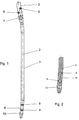
- FIG. 1 shows a side view of a tibia nail
- Fig. 2 shows a section through the distal end region of the tibia nail
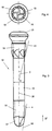
- Fig. 3 is a view of an inventive Locking or clamping screw
- Fig. 4 is a view in Direction of arrow IV of Fig. 3 on the locking screw or clamping screw.
- a Tibialmarknagel 1 is shown, the axis is indicated by dash-dotted lines with 2.
- the axis of the tibia marker nail 1 is here cranked several times and in the direction to the proximal end 3 as well as towards the distal End 4 inclined in the same direction to axis 2 in the central area of the Tibiamarknagels.
- the proximal end has intersecting bores 5 and 6 for the rotation lock.
- the proximal End area provided an elongated hole 7, through which another Locking screw can be inserted, due to the design of the opening as an elongated hole 7 here axial movement of the tibia marker nail 1 and thus dynamization is made possible.
- the distal end 4 again has two bores 8 and 9 with essentially perpendicular to the axis 2 of the bore axis to accommodate locking screws.
- the end region in FIG. 1 is 10 inclined to the rear Bore indicated, which in section in the illustration Fig. 2 is clearly visible.
- this bore 10 is at an angle of approximately 10 ° inclined to the axis 11 of the distal region 4 of the tibia nail arranged so that there is an overall inclination to axis 2 results in the middle area of the tibia nail of about 15 °.
- the holes or perforations 5, 6, 7, 8, 9 and 10 can now conventional locking screws or tension screws be guided to secure anchorage in this way to ensure the tibia nail and, if necessary, additionally Fix splinters successfully.
- suitable tension or locking screw according to the invention is in the 3 and 4 are shown.
- FIG. 3 shows a locking screw 12 which following a screw head 13, a first threaded section 14, a central threadless bolt section 15 and has a terminal threaded portion 16. Outdoors The end of the locking screw is connected to the thread 16 a cutting head 17 is provided, in which, as in particular 4 shows free spaces 18 between threaded sections trained for the removal of the cut material to screw the screw into the bone splitter or to lighten the cortex.
- the middle section 15 of the locking screw is here threadless and has an outer diameter a, which corresponds to the clear cross-section of the tibial nail essentially corresponds.
- the end thread is formed with an outer diameter, which maximum this diameter a of the threadless Area in the middle part, with a definition in Bones on the side opposite the free end the correspondingly larger diameter thread 14 is guaranteed. If the locking screw 12 as a clamping screw to be used, the thread 14 must be smaller Slope as the thread 16 so that when Screwing in a tightening of bone fragments towards the central, threadless region 15 of screw 12 he follows.
- the two are threading portions of threads 14 and 16 in accordance formed with the invention acute-angled.
- the angle, that of the generatrix 19 of the angle-cutting section of the thread 16 with the axis 20 of the screw included is here designated ⁇ and is approximately 10 °.
- For the Angle ⁇ between the generatrix 21 of the thread cutting Section of the thread 14 and the axis 20 was a value of chosen about 15 °.
Abstract
Description
Die Erfindung bezieht sich auf eine Verriegelungsschraube für Implantate, wie z.B. Marknägel, insbesondere Tibiamarknägel, welche eine Durchbrechung oder Ausnehmung des Implantates durchsetzend in eine Knochenwand einschraubbar ist, wobei die Verriegelungsschraube in ihrem mittleren die Durchbrechung oder Ausnehmung des Implantates durchsetzenden Bereich als gewindeloser Bolzen ausgebildet ist, dessen Außendurchmesser der Kontur der Durchbrechung oder der Ausnehmung im Implantat im wesentlichen entspricht und größer oder gleich dem Außendurchmesser des Gewindes am freien Ende der Verriegelungsschraube ist und wobei die Verriegelungsschraube zwischen dem mittleren Bereich und dem Schraubenkopf ein weiteres Gewinde mit dem Durchmesser des mittleren Bereiches übersteigendem Außendurchmesser aufweist.The invention relates to a locking screw for Implants, e.g. Intramedullary nails, especially tibia intramedullary nails, which penetrates an opening or recess in the implant can be screwed into a bone wall, the locking screw in their middle the opening or Recess through the area of the implant as threadless Bolt is formed, the outer diameter of the contour the opening or the recess in the implant essentially corresponds to and greater than or equal to the outer diameter of the thread at the free end of the locking screw and with the locking screw between the middle area and the screw head another thread with the diameter of the central region has an outer diameter exceeding.
Verriegelungsschrauben dienen dazu, Implantate in ihrer gewünschten Position zu halten. Beispielsweise im Zusammenhang mit Marknägeln und insbesondere Tibiamarknägel dienen derartige Verriegelungsschrauben der Festlegung des Marknagels im proximalen und im distalen Bereich, wobei nach der Festlegung Belastungen des Knochens als Querkräfte von den Verriegelungsschrauben aufgenommen werden müssen. Für eine wirkungsvolle Verriegelung werden derartige Schrauben durch entsprechende Durchbrechungen bzw. Bohrungen im proximalen bzw. distalen Bereich eines Marknagels hindurchgesteckt und mit dem Knochen verschraubt. Eine wirksame Festlegung und Aufnahme der Kräfte kann hiebei nur dann gewährleistet sein, wenn der Durchmesser der Schraube mit der lichten Weite der Durchbrechung übereinstimmt, was insbesondere für die Gewährleistung der erforderlichen Rotationsstabilität und für die Entlastung des Knochens bei Belastung von wesentlicher Bedeutung ist. Verriegelungsschrauben, mit welchen derartige Implantate, wie beispielsweise Tibiamarknägel, festgelegt werden, weisen üblicherweise über ihre gesamte axiale Länge ein durchgehendes Gewinde auf, sodaß der Gewindeaußendurchmesser bzw. Schraubenaußendurchmesser im Bereich der Durchbrechung des Implantates und insbesondere des Tibiamarknagels an der Innenwand der entsprechenden Durchbrechung bzw. Bohrung des Implantates anliegt, um die Kräfte als Scherkräfte aufnehmen zu können. Die Ausbildung eines Gewindes im Bereich des Eingriffes der Verriegelungsschrauben in die entsprechende Ausnehmung des Implantates führt aber zu einer Schwächung der Verriegelungsschrauben und zu einer Kerbbelastung, welche hohe Ansprüche an die Festigkeit der Verriegelunggschraube stellt. Derartige Verriegelungsschrauben müssen daher in der Regel überdimensioniert werden, um die gewünschten Querkräfte sicher aufnehmen zu können und es muß daher in aller Regel auch ein entsprechend überdimensioniertes Gewinde in den Knochen eingeschraubt werden. Bedingt durch die erforderlichen Festigkeitseigenschaften und insbesondere die geforderte Aufnahme der Querkräfte durch die Verriegelungsschrauben werden zu allem Überfluß beispielsweise bei der Festlegung und Verriegelung von Tibiamarknägel im proximalen und im distalen Bereich Schrauben unterschiedlicher Durchmesser eingesetzt, um diesen Belastungen gerecht werden zu können.Locking screws are used to place implants in their desired Hold position. For example in connection with Intramedullary nails and in particular tibia intramedullary nails serve such locking screws fixing the intramedullary nail in the proximal and in the distal area, being stressed after setting of the bone as transverse forces from the locking screws must be included. For an effective locking are such screws through appropriate openings or holes in the proximal or distal area of an intramedullary nail put through and screwed to the bone. A effective determination and absorption of the forces can only then be guaranteed if the diameter of the screw with the clear width of the opening agrees, which in particular to ensure the required rotational stability and essential for relieving the bone under stress Meaning is. Locking screws with which such Implants, such as tibia intramedullary nails are usually over their entire axial length continuous thread, so that the outer thread diameter or screw outer diameter in the area of the opening of the Implant and especially the tibial nail on the inner wall the corresponding opening or hole in the implant is present in order to be able to absorb the forces as shear forces. The formation of a thread in the area of the engagement of the locking screws into the corresponding recess of the implant but leads to a weakening of the locking screws and a notch load, which places high demands on strength the locking screw. Such locking screws therefore usually have to be oversized to to be able to safely absorb the desired transverse forces and it must therefore usually a correspondingly oversized Threads are screwed into the bone. Due to the required strength properties and in particular the required absorption of the transverse forces by the locking screws are to make everything abundant, for example, when determining and locking of tibia markers in the proximal and in the distal area screws of different diameters are used, in order to be able to cope with these burdens.
Im Zusammenhang mit sogenannten Spannschrauben, mit welchen es gelingt, Knochensplitter unmittelbar miteinander zu verbinden und gegeneinander zu spannen, ist es bereits bekannt derartige Spannschrauben mit einem mittleren gewindelosen Teilbereich auszustatten. Dieser mittlere gewindelose Teilbereich, wie er beispielsweise den Ausbildungen, wie sie in der EP 695 537 A1 oder EP 856 293 A1 beschrieben und gezeigt sind, zu entnehmen ist, dient aber in erster Linie der Lösung fertigungstechnischer Probleme, da eine derartige Spannschraube über ihre axiale Länge Teilbereiche mit unterschiedlicher Gewindesteigung aufweisen muß, um ein Spannen von Knochenteilen gegeneinander zu ermöglichen, und die Herstellung derartiger unterschiedlicher Gewindesteigung am leichtesten unter Zwischenschaltung eines gewindelosen Abschnittes möglich ist. Die zu diesem Zwecke getroffene Ausbildungn sieht daher immer vor, daß der gewindelose Abschnitt im wesentlichen dem Kerndurchmesser eines der beiden Gewinde entspricht, sodaß derartige Schrauben als Verriegelungsschrauben nicht geeignet sind, da der gewindelose Abschnitt auf geringerem Durchmesser als der Schraubendurchmesser abgesetzt ist. Nach dem Durchstecken einer derartigen Schraube durch eine entsprechende Durchbrechung eines Implantates würde hier immer ein Spiel im Inneren der Durchbrechung verbleiben, welches die gewünschte Verriegelung verhindert.In connection with so-called tension screws, with which it succeeds in connecting bone fragments directly to one another and to tension against each other, it is already known such To equip the clamping screws with a medium threadless section. This middle threadless section, as for example the training as in EP 695 537 A1 or EP 856 293 A1 are described and shown, it can be seen but primarily serves to solve manufacturing problems, because such a tension screw over its axial length Have partial areas with different thread pitch must, in order to enable the clamping of bone parts against each other, and the production of such different thread pitches easiest with the interposition of a threadless Section is possible. The one made for this purpose Training therefore always provides that the threadless section essentially the core diameter of one of the two threads corresponds, so that such screws as locking screws are unsuitable because the unthreaded section is smaller Diameter than the screw diameter is offset. After this Pushing such a screw through a corresponding one Breakthrough of an implant would always be a game here Remain inside the opening, which is the desired one Locking prevented.
Aus der US-A 5 019 079 ist eine Verriegelungsschraube der eingangs genannten Art bekanntgeworden, bei welcher allerdings entsprechend vorgebohrte Öffnungen vorhanden sein müssen, um ein sicheres Einschrauben zu ermöglichen. Insbesondere bei Verwendung derartiger Verriegelungsschrauben für Tibiamarknägel ist es in der Folge erforderlich, daß dem Kopf bzw. dem Betätigungswerkzeug der Schraube abgewandte Ende in eine Innenwand eines Hohlknochens einzuschrauben, wobei bedingt durch anatomische Gegebenheiten in manchen Fällen hier bereits vor dem Zeitpunkt, zu welchem das dem Werkzeug bzw. dem Kopf abgewandte Ende in die Innenwand eingeschraubt werden kann, das größere Gewinde in die Außenwand des Knochens eingeschraubt werden muß. In diesen Fällen wird dieser Einschraubvorgang nicht durch die Spannkräfte des endständigen Gewindes unterstützt und es hat sich gezeigt, daß in Fällen, in welchen das dem Kopf abgewandte Ende noch nicht in die Innenwand eines Knochens eingreift, das weitere Einschrauben derartiger Schrauben nicht ohne weiteres gelingt.From US-A 5 019 079 is a locking screw at the beginning mentioned type became known, in which, however, accordingly Pre-drilled openings must be in place to accommodate a enable safe screwing in. Especially when used such locking screws for tibia mark nails it is subsequently required that the head or the actuating tool the end facing away from the screw in an inner wall of a Screw in the hollow bone, due to anatomical Circumstances in some cases even before the time to which the end facing away from the tool or the head into the The larger thread can be screwed into the inner wall The outer wall of the bone must be screwed in. In these This screwing process is not affected by the clamping forces of the terminal thread and it has been shown that in cases where the end facing away from the head is still does not interfere with the inner wall of a bone, the other It is not easy to screw in such screws.
Die Erfindung zielt nun darauf ab, die Einschraubkräfte bei Verwendung derartiger Verriegelungsschrauben wesentlich zu verringern und insbesondere sicherzustellen, daß auch dann, wenn lediglich das zweite Gewinde, welches zwischen dem gewindelosen Bolzen im mittleren Bereich und dem Kopf der Schraube angeordnet ist, ohne Unterstützung durch das erste Gewinde eingeschraubt werden soll, eine sichere Verankerung ermöglicht wird.The invention now aims to use the screw-in forces to significantly reduce such locking screws and in particular to ensure that even if only the second thread, which is between the threadless Bolts arranged in the middle area and the head of the screw is screwed in without support from the first thread should be securely anchored.
Zur Lösung dieser Aufgabe besteht die erfindungsgemäße Verriegelungsschraube im wesentlichen darin, daß der Übergangsbereich zwischen dem mittleren gewindelosen Bereich der Schraube und dem weiteren Gewinde als Gewindeschneider mit Freiräumen für den Abtransport von geschnittenem Material mit einer kegelstumpfförmigen Hüllfläche ausgebildet ist, deren Erzeugende mit der Achse der Schraube einen Winkel von kleiner als 35°, vorzugsweise kleiner als 25°, einschließen. Dadurch, daß nun der Übergangsbereich zwischen dem mittleren gewindelosen Bereich der Schraube und dem weiteren Gewinde als Gewindeschneider ausgebildet ist, wird dann, wenn die Erzeugenden der kegelstumpfförmigen Hüllfläche dieses Gewindeschneiders mit der Achse einen Winkel von kleiner als 35° einschließen, ein sicheres Einschrauben auch dann gewährleistet, wenn das vordere Ende der Verriegelungsschraube noch nicht in Knochenmaterial eingreift und daher nicht zur Unterstützung der Einschraubbewegung zur Verfügung steht. Die Einhaltung eines derartigen spitzen Winkels hat sich als wesentlich für die Praxis herausgestellt und unterscheidet sich grundsätzlich von den bekannten Gewindeenden, welche üblicherweise Winkel von 45° oder größer zwischen den Erzeugenden der Hüllfläche und der Achse der Schraube aufweisen. Insgesamt wird mit einer derartigen Ausbildung das Einschrauben wesentlich erleichtert und gleichzeitig die Gefahr einer überflüssigen Zerstörung von Knochenmaterial wesentlich herabgesetzt.To solve this problem, the locking screw according to the invention essentially in that the transition area between the middle threadless area of the screw and the further thread as a tap with free space for the Removal of cut material with a truncated cone Envelope surface is formed, the generatrix with the Axis of the screw an angle of less than 35 °, preferably less than 25 °. Because now the transition area between the middle threadless area of the Screw and the other thread designed as a tap is when the generatrix of the frustoconical Envelope surface of this tap with the axis at an angle of less than 35 °, also secure screwing in then ensured when the front end of the locking screw does not yet intervene in bone material and therefore not is available to support the screw-in movement. Compliance with such an acute angle has proven to be emphasized in practice and differs significantly basically from the known thread ends, which are usually An angle of 45 ° or greater between the generators of the Have envelope surface and the axis of the screw. Overall will with such training screwing essential relieved and at the same time the risk of unnecessary Destruction of bone material significantly reduced.
In besonders bevorzugter Weise ist die erfindungsgemäße Schraube dahingehend weitergebildet, daß der Winkel kleiner 20° und vorzugsweise etwa 15° beträgt.The screw according to the invention is particularly preferred further developed in that the angle is less than 20 ° and is preferably about 15 °.
Auch das dem Kopf abgewandte Ende kann in konventioneller Weise als Gewindeschneider ausgebildet sein, wobei ein besonders schonendes und sicheres Einschrauben dann gelingt, wenn die Ausbildung so getroffen ist, daß der dem Kopf abgewandte Endbereich der Schraube gleichfalls als Gewindeschneider ausgebildet ist, dessen Erzeugende der Hüllfläche mit der Achse einen kleineren Winkel als der zwischen den Erzeugenden und der Achse des in Achsrichtung folgenden Gewindeschneiders aufweisen, wobei vorzugsweise der Winkel im dem Kopf abgewandten Endbereich kleiner als 25° und vorzugsweise etwa 10° beträgt. Insgesamt ergibt sich durch Einhaltung der erfindungsgemäßen Kriterien ein besonders leichtes und sicheres Einschrauben der Verriegelungsschraube. Nach einem Durchstecken der Verriegelungsschraube durch die entsprechende Aufnahmebohrung des Implantates gelingt unmittelbar eine Verschraubung mit der hinterliegenden Kortikalis, wobei gleichzeitig oder aber vor dem Einschrauben in die Gegenkortikalis eine Verschraubung in dem den Schraubenkopf benachbarten Bereich mit entsprechend größerem Durchmesser unmittelbar selbstschneidend vorgenommen werden kann.The end facing away from the head can also be used in a conventional manner be designed as a tap, with a particular gentle and safe screwing in succeeds when the training is such that the end region facing away from the head the screw is also designed as a tap, the generatrix of the envelope with the axis is a smaller one Angle than that between the generators and the axis of the in Have the following thread cutter in the axial direction, preferably the angle in the end region facing away from the head is smaller than 25 ° and preferably about 10 °. Overall, it results by observing the criteria according to the invention a special easy and safe screwing in of the locking screw. After inserting the locking screw through the corresponding one The implant is drilled immediately a screw connection to the posterior cortex, whereby at the same time or before screwing into the opposite cortex a screw connection in the one adjacent to the screw head Area with a correspondingly larger diameter immediately can be made self-tapping.
Die Verriegelungsschraube kann für spezielle Fälle gleichzeitig auch die Funktion einer Spannschraube erfüllen, sodaß die Fixierung von Splittern gleichzeitig mit der Verriegelung eines Implantates vorgenommen werden kann. Zu diesem Zwecke kann die Ausbildung so getroffen sein, daß die Gewindesteigung des dem Schraubenkopf benachbarten weiteren Gewindes kleiner als die Gewindesteigung des Gewindes am freien Ende der Schraube gewählt ist.The locking screw can be used for special cases at the same time also perform the function of a clamping screw, so that the fixation of splinters simultaneously with the locking of one Implant can be made. For this purpose the Training must be taken so that the thread pitch of the Screw head adjacent other thread smaller than that Thread pitch of the thread selected at the free end of the screw is.
Für den üblichen Einsatz als Verriegelungsschraube mit entsprechend paßgenauem Eingriff in die Durchbrechung des Implantates kann aber die Ausbildung in konventioneller Weise so gebildet sein, daß die Gewindesteigungen der beiden Gewindeabschnitte gleich gewählt sind.For the usual use as a locking screw with precise fit in the opening of the implant but can be formed in a conventional manner be that the thread pitches of the two threaded sections are chosen equal.
Herstellungstechnisch lassen sich derartige Verriegelungsschrauben besonders einfach dadurch realisieren, daß der Kerndurchmesser des weiteren Gewindes dem Durchmesser des gewindelosen mittleren Bereiches entspricht, wodurch gleichzeitig das Einschrauben der Verriegelungsschraube ohne zusätzliche Bohrung in den Knochen in einem Arbeitsgang ermöglicht wird.Such locking screws can be manufactured Realize particularly simply in that the core diameter further thread the diameter of the threadless corresponds to the middle area, thereby screwing in at the same time the locking screw without additional hole in the bones are made possible in one operation.
Die Erfindung wird nachfolgend anhand eines in der Zeichnung
schematisch dargestellten Ausführungsbeispieles näher erläutert,
wobei in der Zeichnung als Beispiel für den Einsatz einer
Verriegelungsschraube ein Tibiamarknagel gewählt wird. In der
Zeichnung zeigen Fig. 1 eine Seitenansicht eines Tibianagels,
Fig. 2 einen Schnitt durch den distalen Endbereich des Tibianagels
nach Fig. 1, Fig. 3 eine Ansicht einer erfindungsgemäßen
Verriegelungs- oder Spannschraube und Fig. 4 eine Ansicht in
Richtung des Pfeiles IV der Fig. 3 auf die Verriegelungsschraube
bzw. Spannschraube. The invention is described below with reference to a drawing
schematically illustrated embodiment,
being in the drawing as an example of the use of a
Locking screw a tibial nail is selected. In the
1 shows a side view of a tibia nail,
Fig. 2 shows a section through the distal end region of the
In Fig. 1 ist ein Tibiamarknagel 1 dargestellt, dessen Achse
strichpunktiert mit 2 bezeichnet ist. Die Achse des Tibiamarknagels
1 ist hiebei mehrfach gekröpft ausgebildet und in Richtung
zum proximalen Ende 3 ebenso wie in Richtung zum distalen
Ende 4 gleichsinnig geneigt zur Achse 2 im mittleren Bereich des
Tibiamarknagels.In Fig. 1 a
Das proximale Ende weist einander kreuzende Bohrungen 5 und 6
für die Rotationsverriegelung auf. Zusätzlich ist im proximalen
Endbereich ein Langloch 7 vorgesehen, über welches eine weitere
Verriegelungsschraube eingebracht werden kann, wobei aufgrund
der Ausgestaltung der Durchbrechung als Langloch 7 hier eine
axiale Bewegung des Tibiamarknagels 1 und damit eine Dynamisierung
ermöglicht wird.The proximal end has intersecting
Das distale Ende 4 weist wiederum zwei Bohrungen 8 und 9 mit im
wesentlichen orthogonal zur Achse 2 verlaufender Bohrungsachse
für die Aufnahme von Verriegelungsschrauben auf. Im distalen
Endbereich ist in Fig. 1 mit 10 eine nach hinten geneigte
Bohrung angedeutet, welche im Schnitt in der Darstellung nach
Fig. 2 deutlich ersichtlich ist.The
In Fig. 2 ist diese Bohrung 10 unter einem Winkel von etwa 10°
zur Achse 11 des distalen Bereiches 4 des Tibianagels geneigt
angeordnet, sodaß sich insgesamt eine Gesamtneigung zur Achse 2
im mittleren Bereich des Tibianagels von etwa 15° ergibt. Durch
die Bohrungen bzw. Durchbrechungen 5, 6, 7, 8, 9 und 10 können
nun konventionelle Verriegelungsschrauben oder aber Spannschrauben
geführt werden, um auf diese Weise eine sichere Verankerung
des Tibianagels zu gewährleisten und gegebenenfalls zusätzlich
Splitter erfolgreich zu fixieren. Eine für die Verwendung mit
einem derartigen Tibiamarknagel nach den Fig. 1 und 2 geeignete
erfindungsgemäße Spann- bzw. Verriegelungsschraube ist in den
Fig. 3 und 4 dargestellt. In Fig. 2, this
In Fig. 3 ist eine Verriegelungsschraube 12 ersichtlich, welche
im Anschluß an einen Schraubenkopf 13 einen ersten Gewindeabschnitt
14, einen mittleren gewindelosen Bolzenabschnitt 15
und einen endständigen Gewindeabschnitt 16 aufweist. Am freien
Ende der Verriegelungsschraube ist im Anschluß an das Gewinde 16
ein Schneidkopf 17 vorgesehen, bei welchem, wie sich insbesondere
aus Fig. 4 ergibt, zwischen Gewindeabschnitten Freiräume 18
für den Abtransport des geschnittenen Materials ausgebildet
sind, um ein Einschrauben der Schraube im Knochensplitter bzw.
die Kortikalis zu erleichtern.3 shows a
Der mittlere Abschnitt 15 der Verriegelungsschraube ist hiebei
gewindelos ausgebildet und weist einen Außendurchmesser a auf,
welcher dem lichten Querschnitt der Durchbrechungen des Tibiamarknagels
im wesentlichen entspricht. Um die Durchführung der
Verriegelungsschrauben durch die Durchbrechungen zu ermöglichen,
ist das endständige Gewinde mit einem Außendurchmesser ausgebildet,
welcher maximal diesem Durchmesser a des gewindelosen
Bereiches im mittleren Teil entspricht, wobei eine Festlegung im
Knochen an der dem freien Ende gegenüberliegenden Seite durch
das entsprechend größeren Durchmesser aufweisende Gewinde 14
gewährleistet ist. Wenn die Verriegelungsschraube 12 als Spannschraube
eingesetzt werden soll, muß das Gewinde 14 mit geringerer
Steigung als das Gewinde 16 ausgebildet sein, sodaß beim
Einschrauben ein Anziehen von Knochensplittern in Richtung zum
mittleren, gewindelos ausgebildeten Bereich 15 der Schraube 12
erfolgt.The
Wie sich nun unmittelbar aus Fig. 3 ergibt, sind die beiden
gewindeschneidenden Abschnitte der Gewinde 14 und 16 in Übereinstimmung
mit der Erfindung spitzwinkelig ausgebildet. Der Winkel,
der von der Erzeugenden 19 des winkelschneidenden Abschnittes
des Gewindes 16 mit der Achse 20 der Schraube eingeschlossen
wird, ist hiebei mit α bezeichnet und beträgt etwa 10°. Für den
Winkel β zwischen den Erzeugenden 21 des gewindeschneidenden
Abschnittes des Gewindes 14 und der Achse 20 wurde ein Wert von
etwa 15° gewählt.As can be seen directly from FIG. 3, the two are
threading portions of
Claims (7)
Priority Applications (1)
| Application Number | Priority Date | Filing Date | Title |
|---|---|---|---|
| AT01890340T ATE266977T1 (en) | 2000-12-18 | 2001-12-17 | LOCKING SCREW FOR IMPLANTS |
Applications Claiming Priority (2)
| Application Number | Priority Date | Filing Date | Title |
|---|---|---|---|
| AT2000923U | 2000-12-18 | ||
| AT9232000 | 2000-12-18 |
Publications (3)
| Publication Number | Publication Date |
|---|---|
| EP1214914A2 true EP1214914A2 (en) | 2002-06-19 |
| EP1214914A3 EP1214914A3 (en) | 2003-07-16 |
| EP1214914B1 EP1214914B1 (en) | 2004-05-19 |
Family
ID=3502936
Family Applications (1)
| Application Number | Title | Priority Date | Filing Date |
|---|---|---|---|
| EP01890340A Expired - Lifetime EP1214914B1 (en) | 2000-12-18 | 2001-12-17 | Locking screw for implants |
Country Status (3)
| Country | Link |
|---|---|
| EP (1) | EP1214914B1 (en) |
| AT (1) | ATE266977T1 (en) |
| DE (1) | DE50102314D1 (en) |
Cited By (11)
| Publication number | Priority date | Publication date | Assignee | Title |
|---|---|---|---|---|
| WO2004078049A1 (en) | 2003-03-07 | 2004-09-16 | Synthes Ag Chur | Locking screw for an intramedullary nail |
| EP1935361A1 (en) * | 2006-12-19 | 2008-06-25 | Zimmer Technology, Inc. | Bone fixing system |
| US7892234B2 (en) | 2004-06-22 | 2011-02-22 | Synthes Usa, Llc | Intramedullary nail |
| US8066706B2 (en) | 2004-06-30 | 2011-11-29 | Synthes Usa, Llc | Surgical nail |
| US8221419B2 (en) | 2003-08-29 | 2012-07-17 | Synthes Usa, Llc | Intramedullary nail |
| US8465489B2 (en) | 2003-06-12 | 2013-06-18 | Synthes Usa, Llc | Surgical nail |
| US8808292B2 (en) | 2008-11-11 | 2014-08-19 | Zimmer Gmbh | Orthopedic screw |
| CN104173099A (en) * | 2014-08-29 | 2014-12-03 | 南华大学 | Locking screw of minimally invasive lumbosacral vertebrae locking axial fusion internal fixation system |
| US9237909B2 (en) | 2003-07-30 | 2016-01-19 | DePuy Synthes Products, Inc. | Surgical nail |
| US9737347B2 (en) | 2003-06-12 | 2017-08-22 | DePuy Synthes Products, Inc. | Surgical nail |
| US9918757B2 (en) | 2001-10-17 | 2018-03-20 | DePuy Synthes Products, Inc. | Bone fixation system |
Citations (3)
| Publication number | Priority date | Publication date | Assignee | Title |
|---|---|---|---|---|
| US5019079A (en) | 1989-11-20 | 1991-05-28 | Zimmer, Inc. | Bone screw |
| EP0695537A1 (en) | 1994-07-05 | 1996-02-07 | Amp Developpement | Threaded head screw device for setting two bone fragments |
| EP0856293A1 (en) | 1997-02-04 | 1998-08-05 | Patrice Francois Diebold | Bone screw for connecting small bone fragments |
Family Cites Families (2)
| Publication number | Priority date | Publication date | Assignee | Title |
|---|---|---|---|---|
| FR2766355A1 (en) * | 1997-07-25 | 1999-01-29 | Objectif Implants France | Prosthesis medullary shank, e.g. femoral shank of hip prosthesis |
| FR2787989B1 (en) * | 1998-12-30 | 2001-07-13 | Depuy France | SELF-COMPRESSIVE OSTEOSYNTHESIS SCREW FOR SMALL BONE SURGERY |
-
2001
- 2001-12-17 AT AT01890340T patent/ATE266977T1/en not_active IP Right Cessation
- 2001-12-17 EP EP01890340A patent/EP1214914B1/en not_active Expired - Lifetime
- 2001-12-17 DE DE50102314T patent/DE50102314D1/en not_active Expired - Fee Related
Patent Citations (3)
| Publication number | Priority date | Publication date | Assignee | Title |
|---|---|---|---|---|
| US5019079A (en) | 1989-11-20 | 1991-05-28 | Zimmer, Inc. | Bone screw |
| EP0695537A1 (en) | 1994-07-05 | 1996-02-07 | Amp Developpement | Threaded head screw device for setting two bone fragments |
| EP0856293A1 (en) | 1997-02-04 | 1998-08-05 | Patrice Francois Diebold | Bone screw for connecting small bone fragments |
Cited By (16)
| Publication number | Priority date | Publication date | Assignee | Title |
|---|---|---|---|---|
| US10271881B2 (en) | 2001-10-17 | 2019-04-30 | DePuy Synthes Products, Inc. | Bone fixation system |
| US9918757B2 (en) | 2001-10-17 | 2018-03-20 | DePuy Synthes Products, Inc. | Bone fixation system |
| US8888779B2 (en) | 2003-03-07 | 2014-11-18 | DePuy Synthes Products, LLC | Locking screw for an intramedullary nail |
| AU2003206600B2 (en) * | 2003-03-07 | 2007-08-23 | Synthes Gmbh | Locking screw for an intramedullary nail |
| EP2263584A3 (en) * | 2003-03-07 | 2011-04-27 | Synthes GmbH | Locking screw for an intramedullary nail |
| WO2004078049A1 (en) | 2003-03-07 | 2004-09-16 | Synthes Ag Chur | Locking screw for an intramedullary nail |
| US9737347B2 (en) | 2003-06-12 | 2017-08-22 | DePuy Synthes Products, Inc. | Surgical nail |
| US8465489B2 (en) | 2003-06-12 | 2013-06-18 | Synthes Usa, Llc | Surgical nail |
| US9237909B2 (en) | 2003-07-30 | 2016-01-19 | DePuy Synthes Products, Inc. | Surgical nail |
| US8221419B2 (en) | 2003-08-29 | 2012-07-17 | Synthes Usa, Llc | Intramedullary nail |
| US9814500B2 (en) | 2003-08-29 | 2017-11-14 | DePuy Synthes Products, Inc. | Intramedullary nail |
| US7892234B2 (en) | 2004-06-22 | 2011-02-22 | Synthes Usa, Llc | Intramedullary nail |
| US8066706B2 (en) | 2004-06-30 | 2011-11-29 | Synthes Usa, Llc | Surgical nail |
| EP1935361A1 (en) * | 2006-12-19 | 2008-06-25 | Zimmer Technology, Inc. | Bone fixing system |
| US8808292B2 (en) | 2008-11-11 | 2014-08-19 | Zimmer Gmbh | Orthopedic screw |
| CN104173099A (en) * | 2014-08-29 | 2014-12-03 | 南华大学 | Locking screw of minimally invasive lumbosacral vertebrae locking axial fusion internal fixation system |
Also Published As
| Publication number | Publication date |
|---|---|
| EP1214914A3 (en) | 2003-07-16 |
| ATE266977T1 (en) | 2004-06-15 |
| DE50102314D1 (en) | 2004-06-24 |
| EP1214914B1 (en) | 2004-05-19 |
Similar Documents
| Publication | Publication Date | Title |
|---|---|---|
| DE3936703C2 (en) | ||
| EP1677693B1 (en) | Bone plate | |
| EP1096892B1 (en) | Osteosynthesis screw, especially for application by a translaminar vertebral screw | |
| EP0260222B1 (en) | Implant set for osteosynthesis | |
| EP1940306B1 (en) | Thread-forming screw | |
| EP0561295B1 (en) | Externally fastened intramedullary nail | |
| EP0369266B1 (en) | Bone screw | |
| DE60206700T2 (en) | Fastening device for bone parts | |
| EP0654248B1 (en) | Load transfer member for osteosynthesis | |
| DE60213800T2 (en) | Nail and screw for surgical fixation system | |
| DE2807364A1 (en) | BONE SCREW | |
| AT507271B1 (en) | KNOCHENSCHRAUBENSET | |
| DE19829228C1 (en) | Bone fracture fixture with locking-nail with through-hole | |
| DE69726572T2 (en) | Thread-cutting anchoring element | |
| EP0209685A2 (en) | Fixation element for osteosynthesis | |
| CH666176A5 (en) | DEVICE FOR TREATING A BONE AND NAIL FOR SUCH A DEVICE. | |
| EP0917449A1 (en) | Device for attaching fractured hip-joint heads | |
| WO2002038054A2 (en) | Bone screw | |
| EP1214914B1 (en) | Locking screw for implants | |
| EP1415604A1 (en) | Bone fixationsystem | |
| DE19831338C2 (en) | bone screw | |
| DE102005058496A1 (en) | Dental implant, has body provided with external thread that comprises two threads that are superimposed on each other in partial area of external thread, where one of threads has smaller distance from pitch to pitch than other thread | |
| WO2004000146A1 (en) | Bone screw | |
| DE102014208012B3 (en) | osteosynthesis | |
| DE3538238A1 (en) | Osteosynthesis fixing element |
Legal Events
| Date | Code | Title | Description |
|---|---|---|---|
| PUAI | Public reference made under article 153(3) epc to a published international application that has entered the european phase |
Free format text: ORIGINAL CODE: 0009012 |
|
| AK | Designated contracting states |
Kind code of ref document: A2 Designated state(s): AT BE CH CY DE DK ES FI FR GB GR IE IT LI LU MC NL PT SE TR |
|
| AX | Request for extension of the european patent |
Free format text: AL;LT;LV;MK;RO;SI |
|
| PUAL | Search report despatched |
Free format text: ORIGINAL CODE: 0009013 |
|
| AK | Designated contracting states |
Designated state(s): AT BE CH CY DE DK ES FI FR GB GR IE IT LI LU MC NL PT SE TR |
|
| AX | Request for extension of the european patent |
Extension state: AL LT LV MK RO SI |
|
| 17P | Request for examination filed |
Effective date: 20030719 |
|
| GRAP | Despatch of communication of intention to grant a patent |
Free format text: ORIGINAL CODE: EPIDOSNIGR1 |
|
| GRAS | Grant fee paid |
Free format text: ORIGINAL CODE: EPIDOSNIGR3 |
|
| GRAA | (expected) grant |
Free format text: ORIGINAL CODE: 0009210 |
|
| AKX | Designation fees paid |
Designated state(s): AT BE CH CY DE DK ES FI FR GB GR IE IT LI LU MC NL PT SE TR |
|
| RAP1 | Party data changed (applicant data changed or rights of an application transferred) |
Owner name: RUPRECHTER, EVA Owner name: BERNSTEINER, HELGA MAG., |
|
| RIN1 | Information on inventor provided before grant (corrected) |
Inventor name: BERNSTEINER, HERBERT Inventor name: RUPRECHTER, EVA Inventor name: HERTZ, HARALD PRIMARIUS |
|
| AK | Designated contracting states |
Kind code of ref document: B1 Designated state(s): AT BE CH CY DE DK ES FI FR GB GR IE IT LI LU MC NL PT SE TR |
|
| PG25 | Lapsed in a contracting state [announced via postgrant information from national office to epo] |
Ref country code: TR Free format text: LAPSE BECAUSE OF FAILURE TO SUBMIT A TRANSLATION OF THE DESCRIPTION OR TO PAY THE FEE WITHIN THE PRESCRIBED TIME-LIMIT Effective date: 20040519 Ref country code: IE Free format text: LAPSE BECAUSE OF FAILURE TO SUBMIT A TRANSLATION OF THE DESCRIPTION OR TO PAY THE FEE WITHIN THE PRESCRIBED TIME-LIMIT Effective date: 20040519 Ref country code: FI Free format text: LAPSE BECAUSE OF FAILURE TO SUBMIT A TRANSLATION OF THE DESCRIPTION OR TO PAY THE FEE WITHIN THE PRESCRIBED TIME-LIMIT Effective date: 20040519 Ref country code: CY Free format text: LAPSE BECAUSE OF FAILURE TO SUBMIT A TRANSLATION OF THE DESCRIPTION OR TO PAY THE FEE WITHIN THE PRESCRIBED TIME-LIMIT Effective date: 20040519 Ref country code: NL Free format text: LAPSE BECAUSE OF FAILURE TO SUBMIT A TRANSLATION OF THE DESCRIPTION OR TO PAY THE FEE WITHIN THE PRESCRIBED TIME-LIMIT Effective date: 20040519 Ref country code: FR Free format text: LAPSE BECAUSE OF FAILURE TO SUBMIT A TRANSLATION OF THE DESCRIPTION OR TO PAY THE FEE WITHIN THE PRESCRIBED TIME-LIMIT Effective date: 20040519 Ref country code: IT Free format text: LAPSE BECAUSE OF FAILURE TO SUBMIT A TRANSLATION OF THE DESCRIPTION OR TO PAY THE FEE WITHIN THE PRESCRIBED TIME-LIMIT;WARNING: LAPSES OF ITALIAN PATENTS WITH EFFECTIVE DATE BEFORE 2007 MAY HAVE OCCURRED AT ANY TIME BEFORE 2007. THE CORRECT EFFECTIVE DATE MAY BE DIFFERENT FROM THE ONE RECORDED. Effective date: 20040519 |
|
| REG | Reference to a national code |
Ref country code: GB Ref legal event code: FG4D Free format text: NOT ENGLISH |
|
| REG | Reference to a national code |
Ref country code: CH Ref legal event code: EP |
|
| REG | Reference to a national code |
Ref country code: IE Ref legal event code: FG4D Free format text: GERMAN |
|
| REF | Corresponds to: |
Ref document number: 50102314 Country of ref document: DE Date of ref document: 20040624 Kind code of ref document: P |
|
| PG25 | Lapsed in a contracting state [announced via postgrant information from national office to epo] |
Ref country code: SE Free format text: LAPSE BECAUSE OF FAILURE TO SUBMIT A TRANSLATION OF THE DESCRIPTION OR TO PAY THE FEE WITHIN THE PRESCRIBED TIME-LIMIT Effective date: 20040819 Ref country code: GR Free format text: LAPSE BECAUSE OF FAILURE TO SUBMIT A TRANSLATION OF THE DESCRIPTION OR TO PAY THE FEE WITHIN THE PRESCRIBED TIME-LIMIT Effective date: 20040819 Ref country code: DK Free format text: LAPSE BECAUSE OF FAILURE TO SUBMIT A TRANSLATION OF THE DESCRIPTION OR TO PAY THE FEE WITHIN THE PRESCRIBED TIME-LIMIT Effective date: 20040819 |
|
| PG25 | Lapsed in a contracting state [announced via postgrant information from national office to epo] |
Ref country code: ES Free format text: LAPSE BECAUSE OF FAILURE TO SUBMIT A TRANSLATION OF THE DESCRIPTION OR TO PAY THE FEE WITHIN THE PRESCRIBED TIME-LIMIT Effective date: 20040830 |
|
| REG | Reference to a national code |
Ref country code: CH Ref legal event code: NV Representative=s name: OK PAT AG PATENTE MARKEN LIZENZEN |
|
| GBT | Gb: translation of ep patent filed (gb section 77(6)(a)/1977) |
Effective date: 20040826 |
|
| NLV1 | Nl: lapsed or annulled due to failure to fulfill the requirements of art. 29p and 29m of the patents act | ||
| PG25 | Lapsed in a contracting state [announced via postgrant information from national office to epo] |
Ref country code: LU Free format text: LAPSE BECAUSE OF NON-PAYMENT OF DUE FEES Effective date: 20041217 Ref country code: AT Free format text: LAPSE BECAUSE OF NON-PAYMENT OF DUE FEES Effective date: 20041217 |
|
| REG | Reference to a national code |
Ref country code: IE Ref legal event code: FD4D |
|
| PG25 | Lapsed in a contracting state [announced via postgrant information from national office to epo] |
Ref country code: BE Free format text: LAPSE BECAUSE OF NON-PAYMENT OF DUE FEES Effective date: 20041231 Ref country code: MC Free format text: LAPSE BECAUSE OF NON-PAYMENT OF DUE FEES Effective date: 20041231 |
|
| PLBE | No opposition filed within time limit |
Free format text: ORIGINAL CODE: 0009261 |
|
| STAA | Information on the status of an ep patent application or granted ep patent |
Free format text: STATUS: NO OPPOSITION FILED WITHIN TIME LIMIT |
|
| 26N | No opposition filed |
Effective date: 20050222 |
|
| EN | Fr: translation not filed | ||
| BERE | Be: lapsed |
Owner name: *RUPRECHTER EVA Effective date: 20041231 Owner name: *BERNSTEINER HELGA MAG. Effective date: 20041231 |
|
| PGFP | Annual fee paid to national office [announced via postgrant information from national office to epo] |
Ref country code: GB Payment date: 20061213 Year of fee payment: 6 |
|
| PGFP | Annual fee paid to national office [announced via postgrant information from national office to epo] |
Ref country code: CH Payment date: 20061221 Year of fee payment: 6 |
|
| PGFP | Annual fee paid to national office [announced via postgrant information from national office to epo] |
Ref country code: DE Payment date: 20061229 Year of fee payment: 6 |
|
| BERE | Be: lapsed |
Owner name: *BERNSTEINER HELGA MAG. Effective date: 20041231 Owner name: *RUPRECHTER EVA Effective date: 20041231 |
|
| PG25 | Lapsed in a contracting state [announced via postgrant information from national office to epo] |
Ref country code: PT Free format text: LAPSE BECAUSE OF NON-PAYMENT OF DUE FEES Effective date: 20041019 |
|
| REG | Reference to a national code |
Ref country code: CH Ref legal event code: PL |
|
| GBPC | Gb: european patent ceased through non-payment of renewal fee |
Effective date: 20071217 |
|
| PG25 | Lapsed in a contracting state [announced via postgrant information from national office to epo] |
Ref country code: LI Free format text: LAPSE BECAUSE OF NON-PAYMENT OF DUE FEES Effective date: 20071231 Ref country code: CH Free format text: LAPSE BECAUSE OF NON-PAYMENT OF DUE FEES Effective date: 20071231 Ref country code: DE Free format text: LAPSE BECAUSE OF NON-PAYMENT OF DUE FEES Effective date: 20080701 |
|
| PG25 | Lapsed in a contracting state [announced via postgrant information from national office to epo] |
Ref country code: GB Free format text: LAPSE BECAUSE OF NON-PAYMENT OF DUE FEES Effective date: 20071217 |