EP1214986A1 - Ultrasonic atomizer - Google Patents
Ultrasonic atomizer Download PDFInfo
- Publication number
- EP1214986A1 EP1214986A1 EP00127359A EP00127359A EP1214986A1 EP 1214986 A1 EP1214986 A1 EP 1214986A1 EP 00127359 A EP00127359 A EP 00127359A EP 00127359 A EP00127359 A EP 00127359A EP 1214986 A1 EP1214986 A1 EP 1214986A1
- Authority
- EP
- European Patent Office
- Prior art keywords
- ultrasonic atomizer
- substrate board
- substrate
- piezoelectric vibrator
- liquid
- Prior art date
- Legal status (The legal status is an assumption and is not a legal conclusion. Google has not performed a legal analysis and makes no representation as to the accuracy of the status listed.)
- Withdrawn
Links
Images


Classifications
-
- B—PERFORMING OPERATIONS; TRANSPORTING
- B05—SPRAYING OR ATOMISING IN GENERAL; APPLYING FLUENT MATERIALS TO SURFACES, IN GENERAL
- B05B—SPRAYING APPARATUS; ATOMISING APPARATUS; NOZZLES
- B05B17/00—Apparatus for spraying or atomising liquids or other fluent materials, not covered by the preceding groups
- B05B17/04—Apparatus for spraying or atomising liquids or other fluent materials, not covered by the preceding groups operating with special methods
- B05B17/06—Apparatus for spraying or atomising liquids or other fluent materials, not covered by the preceding groups operating with special methods using ultrasonic or other kinds of vibrations
- B05B17/0607—Apparatus for spraying or atomising liquids or other fluent materials, not covered by the preceding groups operating with special methods using ultrasonic or other kinds of vibrations generated by electrical means, e.g. piezoelectric transducers
- B05B17/0638—Apparatus for spraying or atomising liquids or other fluent materials, not covered by the preceding groups operating with special methods using ultrasonic or other kinds of vibrations generated by electrical means, e.g. piezoelectric transducers spray being produced by discharging the liquid or other fluent material through a plate comprising a plurality of orifices
- B05B17/0646—Vibrating plates, i.e. plates being directly subjected to the vibrations, e.g. having a piezoelectric transducer attached thereto
-
- D—TEXTILES; PAPER
- D06—TREATMENT OF TEXTILES OR THE LIKE; LAUNDERING; FLEXIBLE MATERIALS NOT OTHERWISE PROVIDED FOR
- D06F—LAUNDERING, DRYING, IRONING, PRESSING OR FOLDING TEXTILE ARTICLES
- D06F75/00—Hand irons
- D06F75/08—Hand irons internally heated by electricity
- D06F75/22—Hand irons internally heated by electricity with means for supplying liquid to the article being ironed
Definitions
- the invention relates to an ultrasonic atomizer for production of a liquid spray.
- Ultrasonic atomizers are used when the to generating spray mist high demands especially in relation distribution as homogeneous as possible or as possible good meterability. Possible areas of application are e.g. use in painting equipment, air humidification systems, medical devices - where a medical effective aerosol generated in a certain dosage - but also household appliances, such as Iron, in those to generate particularly good work success Ultrasonic atomizers are used to make a to produce water mist that supports the ironing process.
- EP 1 005 917 A1 describes an inhaler with an ultrasonic atomizer described. This consists of a first and a second substrate, and a vibration generator.
- the two substrates and the vibrator are essentially three-dimensional, specially designed bodies.
- the first substrate which is the outlet device for the atomized liquid is very important elaborately designed to the excited main vibration mode optimal support.
- the invention is therefore based on the object of an ultrasonic atomizer indicate which one is easy to manufacture, a favorable radiation behavior with regard to the to be generated Has spray mist and covers a wide range of uses.
- the task is performed by an ultrasonic atomizer solved with a piezoelectric transducer, at which the piezoelectric transducer as a whole-surface table is formed and connected to a substrate board.
- the invention is Ultrasonic atomizer easy to manufacture because it is used to manufacture the essential components of which do not require any special manufacturing steps in which one or more components of the atomizer a complicated three-dimensional geometric shape is given.
- Ultrasonic atomizer not limited to applications, where a relatively small amount of liquid is atomized shall be.
- Ultrasound atomizer understood a plate-like structure which are two flat, parallel interfaces having. Furthermore, this plate-like structure is said to be one have a small thickness compared to its length.
- a board is called the whole area if on one of the Interfaces two with respect to the center of gravity of the panel the opposite edge points always by a straight line Route can be connected, the routes being completely in of the respective area. Minor irregularities on The edge of the respective interface should not be considered become.
- the substrate board advantageously has at least one recess on.
- the targeted geometric design of the recess in the substrate board allows to set the vibration modes of the Formed consisting of piezoelectric vibrator and thus connected substrate board.
- the working frequency of the ultrasonic atomizer targeted to a frequency range far from the hearing limit away to avoid acoustic impairments to avoid during operation.
- the variation in the size and geometric shape of the recess the substrate board also allows targeted influence to take on the size of the atomization process resulting liquid droplets.
- the geometry of the piezoelectric transducer represents the Variation of the geometry of the recess of the substrate plate one technically easy to accomplish task.
- the recess advantageously extends over the geometric one Center of gravity of the substrate board with elliptical, circular or regular polynomial cross section of the substrate plate so about the center. This will make the adjustment to the desired vibration mode particularly easily.
- the piezoelectric vibrator and / or the substrate plate formed as at least essentially round plates.
- the vibrations along the surface of the piezoelectric Schwingers particularly homogeneous.
- the substrate board's job is to set certain vibration modes to stimulate or suppress is one in many Advantageous in terms of symmetrical shape of the substrate board, to achieve this effect as homogeneously as possible.
- round boards are easy to manufacture.
- Both the piezoelectric vibrator is advantageous as well as the substrate board as a round board, the substrate panel having a central hole.
- the symmetry properties come of the components involved are particularly good and complementary to unfolding.
- there is a middle one Hole can be easily made as a recess in the substrate board.
- Steel is a material that can be easily procured or manufactured is. Furthermore, a large number of simple ones and easy processing options for steel.
- the piezoelectric vibrator on the substrate board is advantageous glued on, especially the transducer and substrate board largely glued together.
- An adhesive connection is easy to produce and offers at Ultrasonic atomizer according to the invention the advantage that the most homogeneous possible distribution of the adhesive layer in comparison the vibrations of the piezoelectric vibrator connected to the substrate panel be little affected.
- the substrate board has at least one hole and this is closed by at least one aid.
- the aid has a thickness which is clear is below the thickness of the substrate board.
- Closing the hole in the substrate board with a tool offers the advantage that the especially in operation without Liquid heat generated by the piezoelectric vibrator can be dissipated more easily because the heat on the with aids in contact with the piezoelectric vibrator passes over and is distributed over its surface. If the surface of the aid is at least somewhat larger than the cross section of the hole, the heat input is improved, because the surface of the aid is directly related to the environment communicates. In operation with liquid offers the aid also has the advantage of corrosion protection of the piezoelectric transducer when the feed the liquid to be atomized from that facing away from the transducer Side of the substrate board. Then she kicks no longer in direct contact with the surface of the piezoelectric Oscillator.
- the aid is advantageously a plastic film and / or a paint and / or a metal foil.
- the ultrasonic atomizer in an iron is advantageous used to generate a spray.
- the substrate board 12 has a recess 14 center hole. Both the piezoelectric vibrator 10 as well as the substrate board 12 are in this embodiment designed as round plates.
- the piezoelectric vibrator 10 and the substrate panel 12 form a sandwich arrangement and are preferably glued together flat.
- the one to be atomized This sandwich arrangement is on a liquid Not shown in FIG 1 way can be supplied.
- the substrate board 12 has through openings 16, through which, when operating the ultrasonic atomizer, the one to be atomized or pass through already atomized liquid can.
- the recess 14 of the substrate board 12 can be of geometrical sizes such as. Target length, width, area or diameter be designed so that the one is not closer shown excitation device consisting of excited unit with piezoelectric vibrator 10 and substrate board 12 with a desired working frequency swings.
- FIG. 2 shows a side view of FIG. 2 along the section II-II.
- the passage openings 16 are of a perforated film 18, which is perforated in the present exemplary embodiment Ring disc is covered.
- the not shown Holes in the perforated film 18 preferably have a diameter of approx. 50 ⁇ m. The purpose of these holes is that no liquid can pass through it if the ultrasonic atomizer is not actuated, i.e. the piezoelectric Vibrator is not excited.
- the perforated film 18 is preferably glued flat to the substrate board 12.
- FIG. 3 shows an ultrasonic atomizer 19. This is connected with a tank housing 29, which consists of two by one Partition 31 separate rooms (30, 32) there. In both There is clearing during the operation of the ultrasonic atomizer 16 liquid 34.
- the liquid in the working space 32 is the one which the next time you press a button, not shown Actuator of the ultrasonic atomizer 16 is used for atomization. A particularly good atomization result is obtained if one is possible in the work area 32 even distribution of pressure in the liquid prevails.
- liquid from the storage room 30 are specifically transported to the work area 32 in order to be there occurring during the operation of the ultrasonic atomizer 16 Compensate for pressure fluctuations in the liquid.
- the ultrasonic atomizer 19 further comprises an entire surface piezoelectric vibrator 20, which is on a substrate board 22, which in the present embodiment is designed as a disc, is glued on.
- the substrate board 22 has a central hole, which with a Aid 35, for example closed with a varnish is.
- the thickness of the aid 35 should be compared to the thickness the substrate board 22 may be small.
- the substrate panel 22 also has passage openings 26, which with a annular perforated film 28 or a porous washer are.
- the ultrasonic atomizer 19 is now operated by a Actuating device, not shown, is operated, so the piezoelectric vibrator 20 also experiences Excitation device, not shown, an electrical Excitation which is the unit which is made of piezoelectric Vibrator and substrate panel 22 is made to vibrate. With this excitation, the liquid is atomized into Liquid droplets that are small enough to pass through the Holes of the perforated film 28 to reach and through the passage openings 26 to be ejected in the R direction.
- the tool 35 with which the central hole of the substrate board is closed, then especially improves the Heat dissipation of the piezoelectric vibrator 20 when there is no liquid 34 in the tank housing 29 and the ultrasonic atomizer 19 is operated anyway. Furthermore offers closing the central hole of the substrate board by means of the aid 35 the advantage that the forces which is on the border between piezoelectric vibrator and Substrate board occur, are reduced and so the sensitivity to breakage is reduced.
- the iron 40 includes an ultrasonic atomizer, which is fed with liquid from a tank housing 46 and a perforated film 54, a substrate board 52 and a piezoelectric Contains transducer 48.
- the piezoelectric Vibrator 48 is connected via a connecting line 50 from one Excitation device, not shown, controlled and closed Vibrations stimulated.
- the ultrasonic atomizer or at least whose excitation device is also not one Actuator shown actuates what to swing of the piezoelectric vibrator 48 leads.
- Vibrations form in the tank housing 46 near the piezoelectric vibrator 48 or the substrate board 52 Water droplets that are small enough to not pass through holes of the perforated film 54 to pass through. The water droplets can then pass through the openings of the substrate board 52 and are passed through the openings 44 of the soleplate 42 in the direction of the ironing Ejected good things.
Abstract
Description
Die Erfindung betrifft einen Ultraschallzerstäuber zur Erzeugung eines Flüssigkeits-Sprühnebels.The invention relates to an ultrasonic atomizer for production of a liquid spray.
Ultraschallzerstäuber werden dann eingesetzt, wenn an den zu erzeugenden Sprühnebel hohe Anforderungen besonders in Bezug auf eine möglichst homogene Verteilung oder eine möglichst gute Dosierbarkeit gestellt werden. Mögliche Einsatzgebiete sind hierbei z.B. der Einsatz in Lackiergeräten, Luftbefeuchtungseinrichtungen, medizinischen Geräten - bei denen ein medizinisch wirksames Aerosol in einer bestimmten Dosierung erzeugt werden soll -, aber auch Haushaltsgeräte, wie z.B. Bügeleisen, bei denen zur Erzeugung eines besonders guten Arbeiterfolgs Ultraschallzerstäuber eingesetzt werden, um einen den Bügelprozess unterstützenden Wassernebel zu erzeugen.Ultrasonic atomizers are used when the to generating spray mist high demands especially in relation distribution as homogeneous as possible or as possible good meterability. Possible areas of application are e.g. use in painting equipment, air humidification systems, medical devices - where a medical effective aerosol generated in a certain dosage - but also household appliances, such as Iron, in those to generate particularly good work success Ultrasonic atomizers are used to make a to produce water mist that supports the ironing process.
In der DE 197 35 214 C2 ist ein Bügeleisen gezeigt, welches u.a. eine piezo-elektrische Zerstäubungseinrichtung aufweist. Das piezoelektrische Element der piezoelektrischen Zerstäubungseinrichtung weist dabei eine Anzahl von gezielt angebrachten Öffnungen auf. Die Herstellung eines derartigen piezoelektrischen Elements erfordert daher einen entsprechend aufwendigen Herstellungsprozess.DE 197 35 214 C2 shows an iron which et al has a piezoelectric atomizing device. The piezoelectric element of the piezoelectric atomizer has a number of targeted ones Openings on. The manufacture of such a piezoelectric Elements therefore requires one accordingly complex manufacturing process.
In der EP 1 005 917 A1 ist ein Inhalator mit einem Ultraschallzerstäuber beschrieben. Dieser besteht aus einem ersten und einem zweiten Substrat, sowie aus einem Schwingungserzeuger.EP 1 005 917 A1 describes an inhaler with an ultrasonic atomizer described. This consists of a first and a second substrate, and a vibration generator.
Die beiden Substrate, sowie der Schwinger sind dabei im Wesentlichen dreidimensionale, speziell ausgestaltete Körper. Besonders das erste Substrat, welches die Auslasseinrichtung für die zerstäubte Flüssigkeit beinhaltet, ist dabei sehr aufwendig ausgestaltet, um die angeregte Hauptschwingungsmode optimal zu unterstützen.The two substrates and the vibrator are essentially three-dimensional, specially designed bodies. Especially the first substrate, which is the outlet device for the atomized liquid is very important elaborately designed to the excited main vibration mode optimal support.
Nachteilig dabei ist, dass die Fertigung eines derartig gestalteten Ultraschallzerstäubers aufwendig ist, weil dabei insbesondere komplizierte dreidimensionale Substratkörper hergestellt werden müssen, welche eine ganz bestimmte, genau einzuhaltende Geometrie aufweisen müssen, um den Zerstäubungs-Erfolg sicher zu stellen.The disadvantage here is that the production of such a design Ultrasonic atomizer is expensive because of it especially complicated three-dimensional substrate bodies have to be made, which is a very specific one, exactly geometry must be observed to ensure the atomization success make sure.
In der EP 0 689 879 A1 ist ein Ultraschallzerstäuber beschrieben,
welcher sich besonders für medizinische Anwendungen
eignet, bei denen eine relativ geringe Flüssigkeitsmenge
zerstäubt werden muss. Dazu ist insbesondere ein speziell
gestalteter Koppelkörper vorgesehen, um eine gute Benetzung
mit möglichst wenig zu zerstäubender Medikamentenflüssigkeit
zu gewährleisten.An ultrasonic atomizer is described in
Nachteilig dabei ist, dass dieser Ultraschallzerstäuber nicht zur Zerstäubung von größeren Flüssigkeitsmengen geeignet ist.The disadvantage here is that this ultrasonic atomizer is not is suitable for atomizing larger quantities of liquid.
Der Erfindung liegt daher die Aufgabe zugrunde, einen Ultraschallzerstäuber anzugeben, welcher einfach zu fertigen ist, ein günstiges Abstrahlverhalten bezüglich des zu erzeugenden Sprühnebels aufweist sowie einen breiten Einsatzbereich abdeckt.The invention is therefore based on the object of an ultrasonic atomizer indicate which one is easy to manufacture, a favorable radiation behavior with regard to the to be generated Has spray mist and covers a wide range of uses.
Erfindungsgemäß wird die Aufgabe durch einen Ultraschallzerstäuber mit einem piezoelektrischen Schwinger gelöst, bei welchem der piezoelektrische Schwinger als ganzflächige Tafel ausgebildet und mit einer Substrat-Tafel verbunden ist.According to the invention, the task is performed by an ultrasonic atomizer solved with a piezoelectric transducer, at which the piezoelectric transducer as a whole-surface table is formed and connected to a substrate board.
Im Gegensatz zum Stand der Technik ist der erfindungsgemäße Ultraschallzerstäuber einfach herstellbar, da es zur Herstellung dessen wesentlicher Bestandteile keiner speziellen Herstellungsschritte bedarf, in welchen einem oder mehreren Bestandteilen des Zerstäubers eine komplizierte dreidimensionale geometrische Form verliehen wird.In contrast to the prior art, the invention is Ultrasonic atomizer easy to manufacture because it is used to manufacture the essential components of which do not require any special manufacturing steps in which one or more components of the atomizer a complicated three-dimensional geometric shape is given.
Insbesondere ist der Einsatzbereich des erfindungsgemäßen Ultraschallzerstäubers nicht eingeschränkt auf Anwendungen, bei denen eine relativ geringe Flüssigkeitsmenge zerstäubt werden soll.In particular, the field of application of the invention Ultrasonic atomizer not limited to applications, where a relatively small amount of liquid is atomized shall be.
Unter Tafel soll im Zusammenhang mit dem erfindungsgemäßen Ultraschallzerstäuber ein plattenartiges Gebilde verstanden werden, welches zwei plane, zueinander parallele Grenzflächen aufweist. Des Weiteren soll dieses plattenartige Gebilde eine im Vergleich zu dessen Längenausdehnung geringe Dicke aufweisen.Under blackboard should in connection with the invention Ultrasound atomizer understood a plate-like structure which are two flat, parallel interfaces having. Furthermore, this plate-like structure is said to be one have a small thickness compared to its length.
Eine Tafel wird ganzflächig genannt, wenn auf einer der Grenzflächen zwei bezüglich des Schwerpunkts der Tafel einander der gegenüberliegenden Randpunkte stets durch eine gerade Strecke verbindbar sind, wobei die Strecken vollständig in der jeweiligen Fläche liegen. Geringe Unregelmäßigkeiten am Rand der jeweiligen Grenzfläche sollen dabei nicht beachtet werden.A board is called the whole area if on one of the Interfaces two with respect to the center of gravity of the panel the opposite edge points always by a straight line Route can be connected, the routes being completely in of the respective area. Minor irregularities on The edge of the respective interface should not be considered become.
Vorteilhaft weist die Substrat-Tafel wenigstens eine Aussparung auf.The substrate board advantageously has at least one recess on.
Die gezielte geometrische Gestaltung der Aussparung der Substrat-Tafel gestattet es, festgelegte Schwingungs-Modes des Gebildes bestehend aus piezoelektrischem Schwinger und damit verbundener Substrat-Tafel anzuregen.The targeted geometric design of the recess in the substrate board allows to set the vibration modes of the Formed consisting of piezoelectric vibrator and thus connected substrate board.
So ist es z.B. möglich, die Arbeitsfrequenz des Ultraschallzerstäuber gezielt in ein Frequenzgebiet weit von der Hörgrenze entfernt zu legen, um so akustische Beeinträchtigungen beim Betrieb zu vermeiden. So it is e.g. possible the working frequency of the ultrasonic atomizer targeted to a frequency range far from the hearing limit away to avoid acoustic impairments to avoid during operation.
Die Variation der Größe und geometrischen Gestalt der Aussparung der Substrat-Tafel erlaubt darüber hinaus, gezielt Einfluss zu nehmen auf die Größe der beim Zerstäubungsprozess entstehenden Flüssigkeitströpfchen. Im Vergleich zur Variation der Geometrie des piezoelektrischen Schwingers stellt die Variation der Geometrie der Aussparung der Substrat-Tafel eine technisch leicht zu bewerkstelligende Aufgabe dar.The variation in the size and geometric shape of the recess the substrate board also allows targeted influence to take on the size of the atomization process resulting liquid droplets. Compared to the variation the geometry of the piezoelectric transducer represents the Variation of the geometry of the recess of the substrate plate one technically easy to accomplish task.
Vorteilhaft erstreckt sich die Aussparung über den geometrischen Schwerpunkt der Substrat-Tafel bei elliptischem, kreisförmigem oder regulär-polynomem Querschnitt der Substrat-Tafel also über den Mittelpunkt. Dadurch wird die Anpassung an den gewünschten Schwingungsmodus besonders einfach.The recess advantageously extends over the geometric one Center of gravity of the substrate board with elliptical, circular or regular polynomial cross section of the substrate plate so about the center. This will make the adjustment to the desired vibration mode particularly easily.
In weiterer vorteilhafter Ausgestaltung der Erfindung sind der piezoelektrische Schwinger und/oder die Substrat-Tafel als wenigstens im Wesentlichen runde Tafeln ausgebildet.In a further advantageous embodiment of the invention the piezoelectric vibrator and / or the substrate plate formed as at least essentially round plates.
Dadurch, dass die runde Form vielfältige Symmetrien aufweist, sind die Schwingungen entlang der Oberfläche des piezoelektrischen Schwingers besonders homogen. Dasselbe gilt bei der Verwendung einer im Wesentlichen runden Substrat-Tafel. Da die Substrat-Tafel die Aufgabe hat, bestimmte Schwingungs-Modes anzuregen bzw. zu unterdrücken, ist eine in vielfältiger Hinsicht symmetrische Form der Substrat-Tafel vorteilhaft, um diesen Effekt möglichst homogen zu erzielen. Außerdem sind runde Tafeln leicht herstellbar.Because the round shape has multiple symmetries, are the vibrations along the surface of the piezoelectric Schwingers particularly homogeneous. The same applies to the Use a substantially round substrate board. There the substrate board's job is to set certain vibration modes to stimulate or suppress is one in many Advantageous in terms of symmetrical shape of the substrate board, to achieve this effect as homogeneously as possible. Moreover round boards are easy to manufacture.
Vorteilhaft sind dabei sowohl der piezoelektrische Schwinger als auch die Substrat-Tafel als jeweils runde Tafel ausgebildet, wobei die Substrat-Tafel ein mittiges Loch aufweist.Both the piezoelectric vibrator is advantageous as well as the substrate board as a round board, the substrate panel having a central hole.
In dieser Ausgestaltung der Erfindung kommen die Symmetrieeigenschaften der beteiligten Bestandteile besonders gut und sich ergänzend zur Entfaltung. Darüber hinaus ist ein mittiges Loch als Aussparung der Substrat-Tafel leicht ausführbar. In this embodiment of the invention, the symmetry properties come of the components involved are particularly good and complementary to unfolding. In addition, there is a middle one Hole can be easily made as a recess in the substrate board.
In weiterer vorteilhafter Ausgestaltung der Erfindung besteht die Substrat-Tafel aus Stahl.In a further advantageous embodiment of the invention the steel substrate board.
Stahl ist ein Werkstoff, welcher leicht beschaffbar bzw. herstellbar ist. Des Weiteren ist eine große Anzahl an einfachen und problemlosen Verarbeitungsmöglichkeiten für Stahl bekannt.Steel is a material that can be easily procured or manufactured is. Furthermore, a large number of simple ones and easy processing options for steel.
Vorteilhaft ist der piezoelektrische Schwinger auf die Substrat-Tafel aufgeklebt, insbesondere sind Schwinger und Substrat-Tafel großflächig miteinander verklebt.The piezoelectric vibrator on the substrate board is advantageous glued on, especially the transducer and substrate board largely glued together.
Eine Klebeverbindung ist leicht herstellbar und bietet beim erfindungsgemäßen Ultraschallzerstäuber den Vorteil, dass bei einer möglichst homogenen Verteilung der Klebeschicht im Vergleich zu einer punktuellen Verbindung die Schwingungen des mit der Substrat-Tafel verbundenen piezoelektrischen Schwingers wenig beeinträchtigt werden.An adhesive connection is easy to produce and offers at Ultrasonic atomizer according to the invention the advantage that the most homogeneous possible distribution of the adhesive layer in comparison the vibrations of the piezoelectric vibrator connected to the substrate panel be little affected.
In weiterer vorteilhafter Ausgestaltung der Erfindung weist die Substrat-Tafel wenigstens ein Loch auf und dieses ist durch mindestens ein Hilfsmittel geschlossen.In a further advantageous embodiment of the invention the substrate board has at least one hole and this is closed by at least one aid.
Das Hilfsmittel weist dabei eine Dicke auf, welche deutlich unterhalb der Dicke der Substrat-Tafel liegt.The aid has a thickness which is clear is below the thickness of the substrate board.
Das Schließen des Lochs der Substrat-Tafel durch ein Hilfsmittel bietet den Vorteil, dass die besonders im Betrieb ohne Flüssigkeit entstehende Wärme des piezoelektrischen Schwingers leichter abgeführt werden kann, da die Wärme auf das mit dem piezoelektrischen Schwinger in Kontakt stehende Hilfsmittel übergeht und sich über dessen Oberfläche verteilt. Falls die Oberfläche des Hilfsmittels zumindest etwas größer ist als der Querschnitt des Lochs, ist die Wärmezufuhr verbessert, da die Oberfläche des Hilfsmittels direkt mit der Umgebung in Verbindung steht. Im Betrieb mit Flüssigkeit bietet das Hilfsmittel darüber hinaus den Vorteil eines Korrosionsschutzes des piezoelektrischen Schwingers, wenn die Zufuhr der zu zerstäubenden Flüssigkeit von der dem Schwinger abgewandten Seite der Substrat-Tafel her erfolgt. Sie tritt dann nicht mehr in direkten Kontakt zur Oberfläche des piezoelektrischen Schwingers.Closing the hole in the substrate board with a tool offers the advantage that the especially in operation without Liquid heat generated by the piezoelectric vibrator can be dissipated more easily because the heat on the with aids in contact with the piezoelectric vibrator passes over and is distributed over its surface. If the surface of the aid is at least somewhat larger than the cross section of the hole, the heat input is improved, because the surface of the aid is directly related to the environment communicates. In operation with liquid offers the aid also has the advantage of corrosion protection of the piezoelectric transducer when the feed the liquid to be atomized from that facing away from the transducer Side of the substrate board. Then she kicks no longer in direct contact with the surface of the piezoelectric Oscillator.
Vorteilhaft ist das Hilfsmittel eine Kunststofffolie und/oder ein Lack und/oder eine Metallfolie.The aid is advantageously a plastic film and / or a paint and / or a metal foil.
Die vorher genannten Hilfsmittel gestatten ein besonders leichtes Schließen des Loches ohne großen Aufwand.The aids mentioned above allow a special one easy closing of the hole without much effort.
Vorteilhaft wird der Ultraschallzerstäuber in einem Bügeleisen zur Erzeugung eines Sprühnebels verwendet.The ultrasonic atomizer in an iron is advantageous used to generate a spray.
Die nachfolgenden Zeichnungen veranschaulichen vier Ausführungsbeispiele der Erfindung. Es zeigen:
- FIG 1
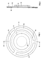
- eine Draufsicht eines piezoelektrischen Schwingers, der mit einer Substrat-Tafel verbunden ist,
- FIG 2
- eine Seitenansicht des in FIG 1 dargestellten, mit einer Substrat-Tafel verbundenen piezoelektrischen Schwingers,
- FIG 3
- einen Längsschnitt durch einen Ultraschallzerstäuber und
- FIG 4
- eine Explosions-Zeichnung eines elektrischen Bügeleisens mit einem Ultraschallzerstäuber.
- FIG. 1
- a plan view of a piezoelectric vibrator, which is connected to a substrate board,
- FIG 2
- 2 shows a side view of the piezoelectric vibrator shown in FIG. 1 connected to a substrate board,
- FIG 3
- a longitudinal section through an ultrasonic atomizer and
- FIG 4
- an exploded view of an electric iron with an ultrasonic atomizer.
In FIG 1 ist ein ganzflächiger piezoelektrischer Schwinger 10
dargestellt, welcher mit einer Substrat-Tafel 12 verbunden
ist. Die Substrat-Tafel 12 weist als eine Aussparung 14 ein
mittiges Loch auf. Sowohl der piezoelektrische Schwinger 10
als auch die Substrat-Tafel 12 sind in dieser Ausführungsform
als runde Tafeln ausgebildet. Der piezoelektrische Schwinger
10 und die Substrat-Tafel 12 bilden eine Sandwich-Anordnung
und sind bevorzugt flächig miteinander verklebt. Die zu zerstäubende
Flüssigkeit ist dieser Sandwich-Anordnung auf eine
in FIG 1 nicht näher dargestellt Weise zuführbar. Vorteilhaft
besitzt die Substrat-Tafel 12 Durchtrittsöffnungen 16, durch
welche beim Betrieb des Ultraschallzerstäubers die zu zerstäubende
oder bereits zerstäubte Flüssigkeit hindurchtreten
kann.1 shows a whole-
Die Aussparung 14 der Substrat-Tafel 12 kann in ihren Geometriegrößen
wie z.B. Länge, Breite, Fläche oder Durchmesser gezielt
so gestaltet werden, dass die über eine nicht näher
dargestellte Erregereinrichtung angeregte Einheit bestehend
aus piezoelektrischem Schwinger 10 und Substrat-Tafel 12 mit
einer gewünschten Arbeitsfrequenz schwingt.The
FIG 2 zeigt eine Seitenansicht der FIG 2 längs des Schnitts
II-II. Die Durchtrittsöffnungen 16 sind von einer Lochfolie
18, welche im vorliegenden Ausführungsbeispiel als gelochte
Ringscheibe ausgeführt ist, bedeckt. Die nicht näher dargestellten
Löcher der Lochfolie 18 haben bevorzugt einen Durchmesser
von ca. 50 µm. Der Sinn dieser Löcher besteht darin,
dass durch diese keine Flüssigkeit hindurchtreten kann, wenn
der Ultraschallzerstäuber nicht betätigt ist, also der piezoelektrische
Schwinger nicht angeregt ist. Die Lochfolie 18
ist mit der Substrat-Tafel 12 bevorzugt flächig verklebt.2 shows a side view of FIG. 2 along the section
II-II. The
FIG 3 zeigt einen Ultraschallzerstäuber 19. Dieser ist verbunden
mit einem Tankgehäuse 29, welches aus zwei durch eine
Trennwand 31 getrennten Räumen (30, 32) besteht. In beiden
Räumen befindet sich beim Betrieb des Ultraschallzerstäubers
16 Flüssigkeit 34. Die Flüssigkeit im Arbeitsraum 32 ist diejenige,
welche bei der nächsten Betätigung einer nicht dargestellten
Betätigungseinrichtung des Ultraschallzerstäubers 16
zur Zerstäubung benutzt wird. Ein besonders gutes Zerstäubungsergebnis
erhält man, wenn im Arbeitsraum 32 eine möglichst
gleichmäßige Verteilung des Drucks in der Flüssigkeit
vorherrscht. Um eine derartige Druckverteilung zu gewährleisten,
kann mit Hilfe der Fördereinrichtung 33, welche bevorzugt
als Pumpe ausgebildet ist, Flüssigkeit vom Vorratsraum
30 gezielt in den Arbeitsraum 32 befördert werden, um dort
während des Betriebs des Ultraschallzerstäubers 16 auftretende
Druckschwankungen in der Flüssigkeit auszugleichen.3 shows an
Der Ultraschallzerstäuber 19 umfasst weiterhin einen ganzflächigen
piezoelektrischen Schwinger 20, welcher auf eine Substrat-Tafel
22, welche im vorliegenden Ausführungsbeispiel
als Scheibe ausgebildet ist, aufgeklebt ist. Die Substrat-Tafel
22 weist ein mittiges Loch auf, welches mit einem
Hilfsmittel 35, beispielsweise mit einem Lack verschlossen
ist. Die Dicke des Hilfsmittels 35 soll im Vergleich zur Dicke
der Substrat-Tafel 22 klein sein. Die Substrat-Tafel 22
weist weiterhin Durchtrittsöffnungen 26 auf, welche mit einer
ringförmigen Lochfolie 28 oder einer porösen Ringscheibe bedeckt
sind.The
Wird nun der Ultraschallzerstäuber 19 betrieben, indem eine
nicht dargestellte Betätigungseinrichtung betätigt wird, so
erfährt der piezoelektrische Schwinger 20 durch eine ebenfalls
nicht dargestellte Erregereinrichtung eine elektrische
Anregung, welche die Einheit, welche aus piezoelektrischem
Schwinger und Substrat-Tafel 22 besteht, zum Schwingen anregt.
Durch diese Anregung wird die Flüssigkeit zerstäubt in
Flüssigkeitströpfchen, welche klein genug sind, um durch die
Löcher der Lochfolie 28 zu gelangen und durch die Durchtrittsöffnungen
26 in Richtung R ausgestoßen zu werden.If the
Das Hilfsmittel 35, mit welcher das mittige Loch der Substrat-Tafel
verschlossen ist, verbessert besonders dann die
Wärmeabfuhr des piezoelektrischen Schwingers 20, wenn sich
keine Flüssigkeit 34 im Tankgehäuse 29 befindet und der Ultraschallzerstäuber
19 trotzdem betätigt wird. Weiterhin bietet
das Verschließen des mittigen Lochs der Substrat-Tafel
mittels des Hilfsmittels 35 den Vorteil, dass die Kräfte,
welche an der Grenze zwischen piezoelektrischem Schwinger und
Substrat-Tafel auftreten, reduziert sind und so die Bruchempfindlichkeit
herabgesetzt ist. The
FIG 4 zeigt ein elektrisches Bügeleisen 40, welches über eine
Anschlussleitung 41 mit elektrischer Energie versorgt wird.
Das Bügeleisen 40 umfasst einen Ultraschallzerstäuber, welcher
aus einem Tankgehäuse 46 mit Flüssigkeit gespeist wird
und eine Lochfolie 54, eine Substrat-Tafel 52 und einen piezoelektrischen
Schwinger 48 enthält. Der piezoelektrische
Schwinger 48 wird über eine Anschlussleitung 50 von einer
nicht dargestellten Erregereinrichtung angesteuert und zu
Schwingungen angeregt. Der Ultraschallzerstäuber bzw. mindestens
dessen Erregereinrichtung wird über eine ebenfalls nicht
dargestellte Betätigungseinrichtung betätigt, was zum Schwingen
des piezoelektrischen Schwingers 48 führt. Durch diese
Schwingungen bilden sich im Tankgehäuse 46 in der Nähe des
piezoelektrischen Schwingers 48 bzw. der Substrat-Tafel 52
Wassertröpfchen, welche klein genug sind, um durch die nicht
näher dargestellten Löcher der Lochfolie 54 hindurchzutreten.
Die Wassertröpfchen können dann durch die Durchtrittsöffnungen
der Substrat-Tafel 52 hindurchgelangen und werden durch
die Durchbrüche 44 der Bügelsohle 42 in Richtung des zu bügelnden
Gutes ausgestoßen.4 shows an
Claims (10)
dadurch gekennzeichnet, dass
der piezoelektrische Schwinger (10) als ganzflächige Tafel ausgebildet und mit einer Substrat-Tafel (12) verbunden ist.Ultrasonic atomizer (16) with a piezoelectric oscillator (10),
characterized in that
the piezoelectric vibrator (10) is designed as a full-surface panel and is connected to a substrate panel (12).
dadurch gekennzeichnet, dass
die Substrat-Tafel (12) wenigstens eine Aussparung (14) aufweist.Ultrasonic atomizer according to claim 1,
characterized in that
the substrate board (12) has at least one recess (14).
dadurch gekennzeichnet, dass
der piezoelektrische Schwinger (10) und/oder die Substrat-Tafel (12) als wenigstens im Wesentlichen runde Tafeln (12) ausgebildet sind.Ultrasonic atomizer according to one of claims 1 or 2,
characterized in that
the piezoelectric vibrator (10) and / or the substrate plate (12) are designed as at least substantially round plates (12).
dadurch gekennzeichnet, dass
der piezoelektrische Schwinger (10) und die Substrat-Tafel (12) als jeweils runde Tafel ausgebildet sind und die Substrat-Tafel (12) ein mittiges Loch aufweist.Ultrasonic atomizer according to claim 3,
characterized in that
the piezoelectric vibrator (10) and the substrate plate (12) are each designed as a round plate and the substrate plate (12) has a central hole.
dadurch gekennzeichnet, dass
die Substrat-Tafel (12) aus Stahl besteht.Ultrasonic atomizer according to one of claims 1 to 4,
characterized in that
the substrate board (12) consists of steel.
dadurch gekennzeichnet, dass
der piezoelektrische Schwinger (10) auf die Substrat-Tafel (12) aufgeklebt ist.Ultrasonic atomizer according to one of claims 1 to 5,
characterized in that
the piezoelectric vibrator (10) is glued to the substrate board (12).
dadurch gekennzeichnet, dass
die Substrat-Tafel (12) wenigstens ein Loch aufweist und dieses durch mindestens ein Hilfsmittel (35) geschlossen ist.Ultrasonic atomizer according to one of claims 2 to 6,
characterized in that
the substrate board (12) has at least one hole and this is closed by at least one auxiliary means (35).
dadurch gekennzeichnet, dass
das Hilfsmittel (35) eine Kunststofffolie und/oder ein Lack und/oder eine Metallfolie ist.Ultrasonic atomizer according to claim 7,
characterized in that
the aid (35) is a plastic film and / or a lacquer and / or a metal film.
Priority Applications (7)
| Application Number | Priority Date | Filing Date | Title |
|---|---|---|---|
| EP00127359A EP1214986A1 (en) | 2000-12-13 | 2000-12-13 | Ultrasonic atomizer |
| EP01991768A EP1341615B1 (en) | 2000-12-13 | 2001-11-29 | Ultrasonic vaporiser |
| JP2002549390A JP2004515353A (en) | 2000-12-13 | 2001-11-29 | Ultrasonic atomizer |
| DE50102639T DE50102639D1 (en) | 2000-12-13 | 2001-11-29 | ultrasonic nebulizer |
| AT01991768T ATE269167T1 (en) | 2000-12-13 | 2001-11-29 | ULTRASONIC ATOMIZER |
| PCT/EP2001/013983 WO2002047828A1 (en) | 2000-12-13 | 2001-11-29 | Ultrasonic vaporiser |
| US10/461,912 US20040256482A1 (en) | 2000-12-13 | 2003-06-13 | Ultrasonic atomizer and steam iron with the ultrasonic atomizer |
Applications Claiming Priority (1)
| Application Number | Priority Date | Filing Date | Title |
|---|---|---|---|
| EP00127359A EP1214986A1 (en) | 2000-12-13 | 2000-12-13 | Ultrasonic atomizer |
Publications (1)
| Publication Number | Publication Date |
|---|---|
| EP1214986A1 true EP1214986A1 (en) | 2002-06-19 |
Family
ID=8170658
Family Applications (2)
| Application Number | Title | Priority Date | Filing Date |
|---|---|---|---|
| EP00127359A Withdrawn EP1214986A1 (en) | 2000-12-13 | 2000-12-13 | Ultrasonic atomizer |
| EP01991768A Expired - Lifetime EP1341615B1 (en) | 2000-12-13 | 2001-11-29 | Ultrasonic vaporiser |
Family Applications After (1)
| Application Number | Title | Priority Date | Filing Date |
|---|---|---|---|
| EP01991768A Expired - Lifetime EP1341615B1 (en) | 2000-12-13 | 2001-11-29 | Ultrasonic vaporiser |
Country Status (6)
| Country | Link |
|---|---|
| US (1) | US20040256482A1 (en) |
| EP (2) | EP1214986A1 (en) |
| JP (1) | JP2004515353A (en) |
| AT (1) | ATE269167T1 (en) |
| DE (1) | DE50102639D1 (en) |
| WO (1) | WO2002047828A1 (en) |
Cited By (2)
| Publication number | Priority date | Publication date | Assignee | Title |
|---|---|---|---|---|
| EP1386672A1 (en) * | 2002-08-02 | 2004-02-04 | PARI GmbH Spezialisten für effektive Inhalation | Fluid droplet production apparatus |
| CN102995370A (en) * | 2012-10-30 | 2013-03-27 | 吴江新劲纺织有限公司 | Quick ironing device |
Families Citing this family (14)
| Publication number | Priority date | Publication date | Assignee | Title |
|---|---|---|---|---|
| US7517568B2 (en) * | 2004-03-23 | 2009-04-14 | The Clorox Company | Packaging for dilute hypochlorite |
| EP1604701B1 (en) * | 2004-06-09 | 2010-12-15 | Microflow Engineering SA | Improved modular liquid spray system |
| US20060251784A1 (en) * | 2005-05-03 | 2006-11-09 | Sells Joel M | Method for cooking meat using steam |
| US20060251785A1 (en) * | 2005-05-06 | 2006-11-09 | Stefania Fraccon | Method for cooking food using steam |
| US20070227930A1 (en) * | 2006-03-28 | 2007-10-04 | Bromberg Steven E | Antimicrobial Product Combination |
| US7867534B2 (en) | 2006-10-18 | 2011-01-11 | Whirlpool Corporation | Cooking appliance with steam generator |
| US7789278B2 (en) * | 2007-04-12 | 2010-09-07 | The Clorox Company | Dual chamber aerosol container |
| US8207477B2 (en) | 2007-11-26 | 2012-06-26 | Whirlpool Corporation | Method for cooking vegetables using steam |
| EP2418318A1 (en) * | 2010-08-12 | 2012-02-15 | Koninklijke Philips Electronics N.V. | Iron featuring liquid phase garment moisturization |
| GB2485553B (en) * | 2010-11-17 | 2014-01-22 | Richards Morphy N I Ltd | Electric iron with nozzle for water mist |
| CA2834171C (en) | 2011-05-13 | 2019-07-30 | Unilever Plc | Spraying device |
| CA159445S (en) | 2014-09-26 | 2015-06-09 | Richards Morphy N I Ltd | Iron |
| US20210053085A1 (en) * | 2018-04-03 | 2021-02-25 | Sunshine Lake Pharma Co., Ltd. | Microporous atomization plate |
| WO2023077295A1 (en) * | 2021-11-03 | 2023-05-11 | 深圳摩尔雾化健康医疗科技有限公司 | Atomization device and atomizer |
Citations (6)
| Publication number | Priority date | Publication date | Assignee | Title |
|---|---|---|---|---|
| JPS61259779A (en) * | 1985-05-14 | 1986-11-18 | Matsushita Electric Ind Co Ltd | Ultrasonic atomizing apparatus |
| EP0614055A1 (en) * | 1993-03-04 | 1994-09-07 | Mario Bonzi | Device for humidifying and ionizing air |
| EP0689879A1 (en) | 1994-06-29 | 1996-01-03 | Siemens Aktiengesellschaft | Ultrasonic atomizer |
| DE19735214C2 (en) | 1996-08-24 | 1998-07-09 | Rowenta Werke Gmbh | Electric iron with an iron soleplate |
| US5823428A (en) * | 1994-06-23 | 1998-10-20 | The Technology Partnership Plc | Liquid spray apparatus and method |
| EP1005917A1 (en) | 1998-12-01 | 2000-06-07 | Microflow Engineering SA | Inhaler with ultrasonic wave nebuliser having nozzle openings superposed on peaks of a standing wave pattern |
Family Cites Families (9)
| Publication number | Priority date | Publication date | Assignee | Title |
|---|---|---|---|---|
| US2855244A (en) * | 1955-06-03 | 1958-10-07 | Bendix Aviat Corp | Sonic liquid-spraying and atomizing apparatus |
| SE349676B (en) * | 1971-01-11 | 1972-10-02 | N Stemme | |
| AU553251B2 (en) * | 1981-10-15 | 1986-07-10 | Matsushita Electric Industrial Co., Ltd. | Arrangement for ejecting liquid |
| US4545561A (en) * | 1982-07-30 | 1985-10-08 | Mcdonnell Douglas Corporation | Piezoelectric valve operator |
| DE3616713A1 (en) * | 1986-05-20 | 1987-11-26 | Siemens Ag | ULTRASONIC MHZ SWINGERS, IN PARTICULAR FOR LIQUID SPRAYING |
| DE69206824C5 (en) * | 1991-12-04 | 2009-07-09 | The Technology Partnership PLC, Melbourn, Royston | DEVICE AND METHOD FOR PRODUCING FLUID FLUIDS |
| GB9903433D0 (en) * | 1999-02-15 | 1999-04-07 | The Technology Partnership Plc | Droplet generation method and device |
| EP1159078B1 (en) * | 1999-03-08 | 2004-12-15 | S. C. Johnson & Son, Inc. | Improved attachment method for piezoelectric elements |
| FR2816963B1 (en) * | 2000-11-22 | 2003-01-24 | Rowenta Werke Gmbh | CORDLESS IRON WITH PIEZOELECTRIC WATER ATOMIZER |
-
2000
- 2000-12-13 EP EP00127359A patent/EP1214986A1/en not_active Withdrawn
-
2001
- 2001-11-29 JP JP2002549390A patent/JP2004515353A/en not_active Withdrawn
- 2001-11-29 AT AT01991768T patent/ATE269167T1/en not_active IP Right Cessation
- 2001-11-29 WO PCT/EP2001/013983 patent/WO2002047828A1/en active IP Right Grant
- 2001-11-29 EP EP01991768A patent/EP1341615B1/en not_active Expired - Lifetime
- 2001-11-29 DE DE50102639T patent/DE50102639D1/en not_active Expired - Lifetime
-
2003
- 2003-06-13 US US10/461,912 patent/US20040256482A1/en not_active Abandoned
Patent Citations (7)
| Publication number | Priority date | Publication date | Assignee | Title |
|---|---|---|---|---|
| JPS61259779A (en) * | 1985-05-14 | 1986-11-18 | Matsushita Electric Ind Co Ltd | Ultrasonic atomizing apparatus |
| EP0614055A1 (en) * | 1993-03-04 | 1994-09-07 | Mario Bonzi | Device for humidifying and ionizing air |
| US5823428A (en) * | 1994-06-23 | 1998-10-20 | The Technology Partnership Plc | Liquid spray apparatus and method |
| EP0689879A1 (en) | 1994-06-29 | 1996-01-03 | Siemens Aktiengesellschaft | Ultrasonic atomizer |
| DE19735214C2 (en) | 1996-08-24 | 1998-07-09 | Rowenta Werke Gmbh | Electric iron with an iron soleplate |
| US6035563A (en) * | 1996-08-24 | 2000-03-14 | Rowenta-Werke Gmbh | Electric iron with a soleplate and piezoelectric sprayer |
| EP1005917A1 (en) | 1998-12-01 | 2000-06-07 | Microflow Engineering SA | Inhaler with ultrasonic wave nebuliser having nozzle openings superposed on peaks of a standing wave pattern |
Non-Patent Citations (1)
| Title |
|---|
| PATENT ABSTRACTS OF JAPAN vol. 011, no. 115 (C - 415) 10 April 1987 (1987-04-10) * |
Cited By (6)
| Publication number | Priority date | Publication date | Assignee | Title |
|---|---|---|---|---|
| EP1386672A1 (en) * | 2002-08-02 | 2004-02-04 | PARI GmbH Spezialisten für effektive Inhalation | Fluid droplet production apparatus |
| WO2004014569A1 (en) * | 2002-08-02 | 2004-02-19 | Pari GmbH Spezialisten für effektive Inhalation | Fluid droplet production apparatus and method |
| US7931212B2 (en) | 2002-08-02 | 2011-04-26 | Pari Pharma Gmbh | Fluid droplet production apparatus and method |
| US20110155768A1 (en) * | 2002-08-02 | 2011-06-30 | Pari Pharma Gmbh | Fluid droplet production apparatus and method |
| US8511581B2 (en) | 2002-08-02 | 2013-08-20 | Pari Pharma Gmbh | Fluid droplet production apparatus and method |
| CN102995370A (en) * | 2012-10-30 | 2013-03-27 | 吴江新劲纺织有限公司 | Quick ironing device |
Also Published As
| Publication number | Publication date |
|---|---|
| JP2004515353A (en) | 2004-05-27 |
| WO2002047828A1 (en) | 2002-06-20 |
| ATE269167T1 (en) | 2004-07-15 |
| EP1341615A1 (en) | 2003-09-10 |
| DE50102639D1 (en) | 2004-07-22 |
| EP1341615B1 (en) | 2004-06-16 |
| US20040256482A1 (en) | 2004-12-23 |
Similar Documents
| Publication | Publication Date | Title |
|---|---|---|
| EP1341615B1 (en) | Ultrasonic vaporiser | |
| DE102009001867B4 (en) | Medical liquid droplet separator | |
| DE102009026636B4 (en) | A method of welding a membrane to a carrier in the manufacture of a membrane nebulizer | |
| DE4142320A1 (en) | ULTRASONIC SPRAYER | |
| WO2020021109A1 (en) | Cleaning device | |
| AT512219B1 (en) | atomizer | |
| DE10392996T5 (en) | Shower head improvements | |
| EP2044968A1 (en) | Fluid vaporiser | |
| DE60111863T2 (en) | LASER WELDING | |
| DE202012105005U1 (en) | Nebulizing structure with an improved spray perforated disc and its fogging device | |
| WO2001039944A1 (en) | Method for modifying wooden surfaces by electrical discharges at atmospheric pressure | |
| DE3034196C2 (en) | Soundproofing panels in double sandwich construction and process for their production | |
| DE19532105A1 (en) | Surface treating three=dimensional workpieces | |
| EP3592486B1 (en) | Electron beam installation and method for working powdered material | |
| WO2004048001A1 (en) | Ultrasonic standing wave spraying arrangement | |
| DD294609A5 (en) | METHOD FOR PRODUCING HIGH-ENERGY ELECTRONIC WALLS WITH HIGH PERFORMANCE | |
| DE2901712C2 (en) | ||
| DE102005024518A1 (en) | Substrate coating method, involves spraying liquid under pressure through nozzle on substrate, where liquid is activated for vibration, which effects monodispersive decay of liquid jet leaving from nozzle | |
| DE102019106163A1 (en) | NOZZLE ARRANGEMENT FOR APPLYING FLUIDS AND METHOD FOR MANUFACTURING A BASIC BODY OF SUCH A NOZZLE ARRANGEMENT | |
| DE102008062619B4 (en) | A microwave plasma source and method of forming a linearly elongated plasma at atmospheric pressure conditions | |
| EP1633493B1 (en) | Standing ultrasonic wave spraying arrangement | |
| DE665941C (en) | Device for atomizing liquids | |
| DE102013004543A1 (en) | Ultrasonic nebulizer | |
| DE102015108444A1 (en) | 3D printing device and 3D printing process | |
| DE10309994B4 (en) | PKF elements for vibrating conveyor system with piezo drive |
Legal Events
| Date | Code | Title | Description |
|---|---|---|---|
| PUAI | Public reference made under article 153(3) epc to a published international application that has entered the european phase |
Free format text: ORIGINAL CODE: 0009012 |
|
| AK | Designated contracting states |
Kind code of ref document: A1 Designated state(s): AT BE CH CY DE DK ES FI FR GB GR IE IT LI LU MC NL PT SE TR |
|
| AX | Request for extension of the european patent |
Free format text: AL;LT;LV;MK;RO;SI |
|
| AKX | Designation fees paid | ||
| REG | Reference to a national code |
Ref country code: DE Ref legal event code: 8566 |
|
| STAA | Information on the status of an ep patent application or granted ep patent |
Free format text: STATUS: THE APPLICATION IS DEEMED TO BE WITHDRAWN |
|
| 18D | Application deemed to be withdrawn |
Effective date: 20021220 |