EP1216937A1 - Corrugated flight module - Google Patents
Corrugated flight module Download PDFInfo
- Publication number
- EP1216937A1 EP1216937A1 EP01811230A EP01811230A EP1216937A1 EP 1216937 A1 EP1216937 A1 EP 1216937A1 EP 01811230 A EP01811230 A EP 01811230A EP 01811230 A EP01811230 A EP 01811230A EP 1216937 A1 EP1216937 A1 EP 1216937A1
- Authority
- EP
- European Patent Office
- Prior art keywords
- belt
- link ends
- intermediate portion
- openings
- module
- Prior art date
- Legal status (The legal status is an assumption and is not a legal conclusion. Google has not performed a legal analysis and makes no representation as to the accuracy of the status listed.)
- Granted
Links
Images


Classifications
-
- B—PERFORMING OPERATIONS; TRANSPORTING
- B65—CONVEYING; PACKING; STORING; HANDLING THIN OR FILAMENTARY MATERIAL
- B65G—TRANSPORT OR STORAGE DEVICES, e.g. CONVEYORS FOR LOADING OR TIPPING, SHOP CONVEYOR SYSTEMS OR PNEUMATIC TUBE CONVEYORS
- B65G17/00—Conveyors having an endless traction element, e.g. a chain, transmitting movement to a continuous or substantially-continuous load-carrying surface or to a series of individual load-carriers; Endless-chain conveyors in which the chains form the load-carrying surface
- B65G17/06—Conveyors having an endless traction element, e.g. a chain, transmitting movement to a continuous or substantially-continuous load-carrying surface or to a series of individual load-carriers; Endless-chain conveyors in which the chains form the load-carrying surface having a load-carrying surface formed by a series of interconnected, e.g. longitudinal, links, plates, or platforms
- B65G17/08—Conveyors having an endless traction element, e.g. a chain, transmitting movement to a continuous or substantially-continuous load-carrying surface or to a series of individual load-carriers; Endless-chain conveyors in which the chains form the load-carrying surface having a load-carrying surface formed by a series of interconnected, e.g. longitudinal, links, plates, or platforms the surface being formed by the traction element
-
- B—PERFORMING OPERATIONS; TRANSPORTING
- B65—CONVEYING; PACKING; STORING; HANDLING THIN OR FILAMENTARY MATERIAL
- B65G—TRANSPORT OR STORAGE DEVICES, e.g. CONVEYORS FOR LOADING OR TIPPING, SHOP CONVEYOR SYSTEMS OR PNEUMATIC TUBE CONVEYORS
- B65G17/00—Conveyors having an endless traction element, e.g. a chain, transmitting movement to a continuous or substantially-continuous load-carrying surface or to a series of individual load-carriers; Endless-chain conveyors in which the chains form the load-carrying surface
- B65G17/30—Details; Auxiliary devices
- B65G17/32—Individual load-carriers
-
- B—PERFORMING OPERATIONS; TRANSPORTING
- B65—CONVEYING; PACKING; STORING; HANDLING THIN OR FILAMENTARY MATERIAL
- B65G—TRANSPORT OR STORAGE DEVICES, e.g. CONVEYORS FOR LOADING OR TIPPING, SHOP CONVEYOR SYSTEMS OR PNEUMATIC TUBE CONVEYORS
- B65G2201/00—Indexing codes relating to handling devices, e.g. conveyors, characterised by the type of product or load being conveyed or handled
- B65G2201/02—Articles
-
- B—PERFORMING OPERATIONS; TRANSPORTING
- B65—CONVEYING; PACKING; STORING; HANDLING THIN OR FILAMENTARY MATERIAL
- B65G—TRANSPORT OR STORAGE DEVICES, e.g. CONVEYORS FOR LOADING OR TIPPING, SHOP CONVEYOR SYSTEMS OR PNEUMATIC TUBE CONVEYORS
- B65G2201/00—Indexing codes relating to handling devices, e.g. conveyors, characterised by the type of product or load being conveyed or handled
- B65G2201/06—Articles and bulk
Definitions
- the present invention relates to modular conveyor belts and more specifically to modular conveying belts having upstanding flights for holding material on a moving belt.
- Upstanding flights for holding material on a modular conveyor belt are typically formed with either flat planar surfaces or with vertical ribs.
- the flat planar surfaces have some drawbacks including the fact that wet particles tend to cling to the flat surfaces.
- vertical ribs In order to prevent the conveyed items from clinging to the flight modules, vertical ribs have been added to the planar flights. The vertical ribs prevent wet food particles such as sliced carrots from sticking to the flights.
- these type of flights have been harder to clean because of the corners created by the ribs. Particles may become trapped in the corners created by the ribs and may resist being removed by sprayed water.
- the surface of the flight module must also be easy to clean so that it is suitable for conveying food items and the like.
- U.S. Patent No. 4,832,183 to Lapeyre relates to an endless loop conveyor belt having a module with a conveying member.
- the top side of each module defines an area for attaching a conveying member and the conveying member has a bottom side or attaching portion which cooperates with the area on the top side of the base member of the module.
- the conveying members may include openings, vertical pins and spikes.
- U.S. Patent No. 4,213,527 to Lapeyre et al. describes a chain link conveyor comprising interlinked modules.
- Fig. 11 shows a flight module having a vertically undulated surface useful for picking up both processed fruit and conveying it along the conveyor. The undulated surface is described as preventing the fruit from sticking to the module.
- U.S. Patent No. 5,490,591 to Faulkner relates to an endless loop conveyor formed of interlinked modules. The use of a reversed-bend cleat having a product-carrying surface and a product-releasing surface is shown.
- U.S. Patent No. 5,165,514 to Faulkner describes conveyor belt modules comprising a flight projection having a forward face and a rearward face and first and second end connectors.
- the connectors cooperate with those on an adjacent module to maintain alignment of the faces in side-by-side flights.
- U.S. Patent No. 2,884,935 to Fox relates to a conveyor type dishwasher having upstanding fingers.
- an upstanding flight module having a shape that provides high strength/rigidity relative to its weight (thereby reducing manufacturing costs and improving performance), that is easy to clean, and that prevents the items being conveyed from sticking to the surface of the flights.
- the present invention meets the above-described need by providing a flight module for use in a modular conveying belt according to independent Claim 1 and a modular conveying belt according to independent Claim 7.
- Preferred embodiments are defined in the dependent claims.
- the flight module includes an intermediate portion having an upstanding wall that extends therefrom.
- the upstanding wall is corrugated in a direction transverse to the direction of belt travel.
- the corrugation provides rigidity to withstand impacts from either the top or the front of the module.
- the rigidity and impact resistance of the flight modules provides strength for loading material onto the belts.
- the corrugation provides for equal strength at a reduced thickness in comparison to other flight modules. Accordingly, the corrugated design reduces the material costs associated with manufacturing the flight modules.
- the corrugated shape of the flight modules also eliminates the flat surfaces that are associated with straight-wall designs and that create problems with wet particles clinging to the flat surfaces. Finally, since the corrugated flights have all smooth and rounded surfaces they are easier to clean than the ribbed flights.
- a first plurality of link ends extend outwardly from the intermediate portion and have openings defined therein that are transverse to the direction of belt travel.
- a second plurality of link ends extend outwardly from the intermediate portion in a direction opposite to the first plurality of link ends.
- the second plurality of link ends also have openings defined therein that are transverse to the direction of belt travel.
- the link ends are arranged such that the openings in respective link ends are capable of aligning when a pair of adjacent belt modules are juxtaposed.
- a pivot rod journaled in the aligned apertures of the side-by-side and end-to-end connected modules forms a hinge between adjacent rows. Rows of belt modules are connected together to form an endless conveyor belt capable of articulating about a drive sprocket.
- the present invention may be used with open grid belts or flat belts. Also, the flight modules of the present invention may be used with both straight-running and radius belts.
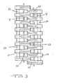
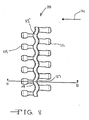
- a modular conveying belt 10 is formed from the juxtaposition of belt modules 13, 16, and 19.
- the direction of belt travel is indicated by arrow 20, however, the belt 10 of the present invention may also travel in the opposite direction.
- Module 16 is commonly referred to as a flight module.
- An upstanding wall or flight 22 holds the materials (not shown) that are being conveyed on the moving belt 10 to prevent them from slipping.
- the module 16 of the present invention has vertical openings 25 for use in an open grid style belt.
- the belt modules 13, 16, and 19 are preferably manufactured from plastic or other materials suitable for use with the conveying of food items.
- the plastic modules are preferably thermoformed through a plastic molding process as known to those of ordinary skill in the art.
- Plastic belts are relatively inexpensive, easy to clean and durable. Also, because they do not corrode and are light-weight, they are used widely, especially in conveying food products.
- the modules 13, 16, and 19 shown in Fig. 1 are arranged in end-to-end fashion to form the belt 10. The individual modules 13, 16, or 19 can also be placed alongside like modules to form belts 10 of varying widths.
- a plurality of first link ends 28 are disposed on the left hand side of module 13 and a plurality of second link ends 31 are disposed on the right hand side of module 13.
- module 16 also includes a plurality of first link ends 34 and a plurality of second link ends 37.
- module 19 also includes a plurality of first link ends 40 and a plurality of second link ends 43 in the same orientation.
- the second link ends 31 have a plurality of apertures 49 defined therein.
- the apertures 49 are capable of aligning with apertures 46 disposed in the first plurality of link ends 34 disposed on the adjacent module 16.
- a pivot rod 52 shown in phantom lines is capable of being journaled in the aligned apertures of the end-to-end connected modules 13 and 16 and forms a hinge between adjacent rows.
- Rows of belt modules 13, 16, and 19 are connected together to form an endless conveyor belt 10 capable of articulating about a drive sprocket (not shown).
- Modules 13, 16, and 19 have intermediate sections 60, 63, and 66, respectively.
- the intermediate sections 60 and 66 corresponding to modules 13 and 19 extend transverse to the direction 20 of belt travel.
- Modules 13 and 19 do not have an upstanding wall or flight 22.
- the intermediate sections 60 and 66 for these modules are substantially flat and are defined by substantially straight walls 70 between successive link ends.
- the intermediate section 63 disposed on module 16 contains the upstanding wall or flight 22.
- the upstanding wall 22 is disposed substantially perpendicular to a planar surface defined by the belt modules 13, 16, and 19.
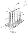
- belt module 16 is isolated and the upstanding wall or flight 22 is shown in greater detail.
- the flight 22 has a middle section 71 that is substantially straight.
- the flight 22 also has a plurality of curved sections 74 that form a corrugated shape.
- Stabilizer bars 76 are connected between the link ends to provide stability.
- the bars 76 are disposed toward the intermediate section such that adjacent link ends have clearance to intercalate.
- a top wall portion 73 of the middle section 71 is approximately straight along a longitudinal axis 79 that is disposed perpendicular to the direction of belt travel.
- the top edge 82 of the flight 22 is rounded.
- Other shapes for the top of the flight 22 may also be suitable.
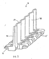
- the straight middle section 71 is not required and as best shown in Fig. 7 the curved sections 74 of the flight 22 may extend all the way to the top surface 82 of the flight 22.
- the lower wall portion 86 has a corrugated shape as shown in Figs. 2 and 5. As shown in Fig. 2, the wall portion 86 alternates between edges 85 of the respective vertical openings 25.
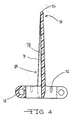
- the corrugated flight 22 is shown in cross-section.
- the flight 22 includes a vertical wall 90 having the curved section 74 that is corrugated such that section 74 curves inward and outward alternating between concave and convex.
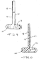
- an alternate embodiment of the present invention comprises a belt module 100 suitable for use in a radius belt (not shown) capable of following a curved path.
- a radius belt has round openings and elongated openings that allow adjoining belt modules to collapse or to fan out depending on which way the belt turns. Accordingly, the side of the belt on the inside of the curve collapses and the side of the belt on the outside of the curve fans out.
- Belt module 100 has a round opening 103 and an elongated slot 106 (Fig. 9). The slot 106 is elongated in the direction of belt travel.
- the belt module 100 also includes a first set of link ends 109 and a second set of link ends 112 connected by an intermediate section 115.
- the second set of link ends 112 are disposed on the opposite side of the intermediate section 115 from the first set of link ends 109.
- the intermediate section 115 includes a vertical flight 118 (best shown in Figs. 9 and 10).
- the vertical flight 118 is curved in corrugated fashion along a longitudinal axis of the link module 100 that is disposed transverse to the direction of belt travel indicated by arrow 121.
- the flight 118 includes a pair of opposed curved surfaces 124 and 127 that form an alternating or corrugated pattern.
Abstract
Description
- The present invention relates to modular conveyor belts and more specifically to modular conveying belts having upstanding flights for holding material on a moving belt.
- Upstanding flights for holding material on a modular conveyor belt are typically formed with either flat planar surfaces or with vertical ribs. The flat planar surfaces have some drawbacks including the fact that wet particles tend to cling to the flat surfaces. In order to prevent the conveyed items from clinging to the flight modules, vertical ribs have been added to the planar flights. The vertical ribs prevent wet food particles such as sliced carrots from sticking to the flights. However, these type of flights have been harder to clean because of the corners created by the ribs. Particles may become trapped in the corners created by the ribs and may resist being removed by sprayed water.
- Another consideration in the design of upstanding flight modules is that the flights must have sufficient strength to withstand relatively heavy impacts associated with the loading of the materials to be conveyed onto the belt.
- Finally, the surface of the flight module must also be easy to clean so that it is suitable for conveying food items and the like.
- There have been many attempts at providing upstanding flights for holding material on a moving modular belt. U.S. Patent No. 4,832,183 to Lapeyre relates to an endless loop conveyor belt having a module with a conveying member. The top side of each module defines an area for attaching a conveying member and the conveying member has a bottom side or attaching portion which cooperates with the area on the top side of the base member of the module. The conveying members may include openings, vertical pins and spikes.
- U.S. Patent No. 4,213,527 to Lapeyre et al. describes a chain link conveyor comprising interlinked modules. Fig. 11 shows a flight module having a vertically undulated surface useful for picking up both processed fruit and conveying it along the conveyor. The undulated surface is described as preventing the fruit from sticking to the module.
- U.S. Patent No. 5,490,591 to Faulkner relates to an endless loop conveyor formed of interlinked modules. The use of a reversed-bend cleat having a product-carrying surface and a product-releasing surface is shown.
- U.S. Patent No. 5,165,514 to Faulkner describes conveyor belt modules comprising a flight projection having a forward face and a rearward face and first and second end connectors. The connectors cooperate with those on an adjacent module to maintain alignment of the faces in side-by-side flights.
- U.S. Patent No. 2,884,935 to Fox relates to a conveyor type dishwasher having upstanding fingers.
- Despite these efforts, there remains a need for an upstanding flight module having a shape that provides high strength/rigidity relative to its weight (thereby reducing manufacturing costs and improving performance), that is easy to clean, and that prevents the items being conveyed from sticking to the surface of the flights.
- The present invention meets the above-described need by providing a flight module for use in a modular conveying belt according to
independent Claim 1 and a modular conveying belt according to independent Claim 7. Preferred embodiments are defined in the dependent claims. - The flight module includes an intermediate portion having an upstanding wall that extends therefrom. The upstanding wall is corrugated in a direction transverse to the direction of belt travel. The corrugation provides rigidity to withstand impacts from either the top or the front of the module. The rigidity and impact resistance of the flight modules provides strength for loading material onto the belts. Also, the corrugation provides for equal strength at a reduced thickness in comparison to other flight modules. Accordingly, the corrugated design reduces the material costs associated with manufacturing the flight modules. The corrugated shape of the flight modules also eliminates the flat surfaces that are associated with straight-wall designs and that create problems with wet particles clinging to the flat surfaces. Finally, since the corrugated flights have all smooth and rounded surfaces they are easier to clean than the ribbed flights.
- In one embodiment of the invention, a first plurality of link ends extend outwardly from the intermediate portion and have openings defined therein that are transverse to the direction of belt travel. A second plurality of link ends extend outwardly from the intermediate portion in a direction opposite to the first plurality of link ends. The second plurality of link ends also have openings defined therein that are transverse to the direction of belt travel. The link ends are arranged such that the openings in respective link ends are capable of aligning when a pair of adjacent belt modules are juxtaposed. A pivot rod journaled in the aligned apertures of the side-by-side and end-to-end connected modules forms a hinge between adjacent rows. Rows of belt modules are connected together to form an endless conveyor belt capable of articulating about a drive sprocket.
- The present invention may be used with open grid belts or flat belts. Also, the flight modules of the present invention may be used with both straight-running and radius belts.
- The invention is illustrated in the drawings in which like reference characters designate the same or similar parts throughout the figures of which:
- Fig. 1 is a top plan view of a modular conveying belt containing a flight module of the present invention;
- Fig. 2 is a top plan view of a flight module of the present invention;
- Fig. 3 is a bottom plan view of the flight module;
- Fig. 4 is a cross-sectional view taken along lines 4-4 of Fig. 2;
- Fig. 5 is a partial perspective view of the flight module;
- Fig. 6 is a top plan view of an alternate embodiment of the flight module of the present invention;
- Fig. 7 is a perspective view of the flight module shown in Fig. 6;
- Fig. 8 is a top plan view of an alternate embodiment of the flight module for use with a radius belt;
- Fig. 9 is an end view of the flight module of Fig. 8; and,
- Fig. 10 is a cross-sectional view taken along lines 10-10 of Fig. 8.
-
- Referring to Figs. 1-10, and initially to Fig. 1, a
modular conveying belt 10 is formed from the juxtaposition ofbelt modules 13, 16, and 19. For reference purposes, the direction of belt travel is indicated byarrow 20, however, thebelt 10 of the present invention may also travel in the opposite direction.Module 16 is commonly referred to as a flight module. An upstanding wall orflight 22 holds the materials (not shown) that are being conveyed on the movingbelt 10 to prevent them from slipping. Themodule 16 of the present invention hasvertical openings 25 for use in an open grid style belt. Thebelt modules 13, 16, and 19 are preferably manufactured from plastic or other materials suitable for use with the conveying of food items. The plastic modules are preferably thermoformed through a plastic molding process as known to those of ordinary skill in the art. Plastic belts are relatively inexpensive, easy to clean and durable. Also, because they do not corrode and are light-weight, they are used widely, especially in conveying food products. Themodules 13, 16, and 19 shown in Fig. 1 are arranged in end-to-end fashion to form thebelt 10. Theindividual modules 13, 16, or 19 can also be placed alongside like modules to formbelts 10 of varying widths. - With reference to the orientation of Fig. 1, a plurality of first link ends 28 are disposed on the left hand side of module 13 and a plurality of second link ends 31 are disposed on the right hand side of module 13. Similarly,
module 16 also includes a plurality of first link ends 34 and a plurality of second link ends 37. Finally, module 19 also includes a plurality of first link ends 40 and a plurality of second link ends 43 in the same orientation. - With reference to module 13, the second link ends 31 have a plurality of
apertures 49 defined therein. Theapertures 49 are capable of aligning withapertures 46 disposed in the first plurality of link ends 34 disposed on theadjacent module 16. Apivot rod 52 shown in phantom lines is capable of being journaled in the aligned apertures of the end-to-end connectedmodules 13 and 16 and forms a hinge between adjacent rows. Rows ofbelt modules 13, 16, and 19 are connected together to form anendless conveyor belt 10 capable of articulating about a drive sprocket (not shown). -
Modules 13, 16, and 19 haveintermediate sections 60, 63, and 66, respectively. The intermediate sections 60 and 66 corresponding to modules 13 and 19 extend transverse to thedirection 20 of belt travel. Modules 13 and 19 do not have an upstanding wall orflight 22. The intermediate sections 60 and 66 for these modules are substantially flat and are defined by substantially straight walls 70 between successive link ends. In contrast, theintermediate section 63 disposed onmodule 16 contains the upstanding wall orflight 22. Theupstanding wall 22 is disposed substantially perpendicular to a planar surface defined by thebelt modules 13, 16, and 19. - In Figs. 2-3,
belt module 16 is isolated and the upstanding wall orflight 22 is shown in greater detail. Theflight 22 has a middle section 71 that is substantially straight. Theflight 22 also has a plurality ofcurved sections 74 that form a corrugated shape. - Stabilizer bars 76 are connected between the link ends to provide stability. The
bars 76 are disposed toward the intermediate section such that adjacent link ends have clearance to intercalate. - With reference to Figs. 4-5, a
top wall portion 73 of the middle section 71 is approximately straight along alongitudinal axis 79 that is disposed perpendicular to the direction of belt travel. Thetop edge 82 of theflight 22 is rounded. Other shapes for the top of theflight 22 may also be suitable. As shown in Figs. 6-7 for straight-running belt modules and in Figs. 8-10 for radius belt modules, the straight middle section 71 is not required and as best shown in Fig. 7 thecurved sections 74 of theflight 22 may extend all the way to thetop surface 82 of theflight 22. Returning to Fig. 5, thelower wall portion 86 has a corrugated shape as shown in Figs. 2 and 5. As shown in Fig. 2, thewall portion 86 alternates betweenedges 85 of the respectivevertical openings 25. - In Fig. 4 the
corrugated flight 22 is shown in cross-section. As shown, theflight 22 includes avertical wall 90 having thecurved section 74 that is corrugated such thatsection 74 curves inward and outward alternating between concave and convex. - In Figs. 8-10, an alternate embodiment of the present invention comprises a
belt module 100 suitable for use in a radius belt (not shown) capable of following a curved path. As known to those of ordinary skill in the art, a radius belt has round openings and elongated openings that allow adjoining belt modules to collapse or to fan out depending on which way the belt turns. Accordingly, the side of the belt on the inside of the curve collapses and the side of the belt on the outside of the curve fans out.Belt module 100 has around opening 103 and an elongated slot 106 (Fig. 9). Theslot 106 is elongated in the direction of belt travel. - The
belt module 100 also includes a first set of link ends 109 and a second set of link ends 112 connected by an intermediate section 115. The second set of link ends 112 are disposed on the opposite side of the intermediate section 115 from the first set of link ends 109. The intermediate section 115 includes a vertical flight 118 (best shown in Figs. 9 and 10). Thevertical flight 118 is curved in corrugated fashion along a longitudinal axis of thelink module 100 that is disposed transverse to the direction of belt travel indicated by arrow 121. Theflight 118 includes a pair of opposedcurved surfaces - While the invention has been described in connection with certain embodiments, it is not intended to limit the scope of the invention to the particular forms set forth, but, on the contrary, it is intended to cover such alternatives, modifications, and equivalents as may be included within the spirit and scope of the invention as defined by the appended claims.
Claims (11)
- A flight module (16; 100) for use in an endless modular conveying belt (10) capable of articulating about a sprocket in a direction (20; 121) of belt travel, comprising:an intermediate portion (63; 115) having an upstanding wall (22; 118) extending therefrom, the upstanding wall (22; 118) being corrugated in a direction transverse to the direction (20; 121) of belt travel;a first plurality of link ends (34; 109) extending outwardly from the intermediate portion (63; 115) and having openings (46; 103) transverse to the direction (20; 121) of belt travel defined therein; and,a second plurality of link ends (37; 112) extending outwardly from the intermediate portion (63; 115) in a direction opposite to the first plurality of link ends (34; 109) and having openings (106) transverse to the direction (20; 121) of belt travel defined therein.
- The flight module (16) of Claim 1, wherein the module (16) further comprises vertical openings (25) defined therein.
- The flight module of Claim 1, wherein the module has a flat, solid top surface.
- The flight module (100) of Claim 1, wherein at least one of the openings (106) is elongated in the direction (20; 121) of belt travel such that the flight module (100) is capable of being intercalated into a modular belt for use with a curved pathway.
- The flight module (16) of Claim 1, wherein the corrugated portion (86) is disposed between the intermediate portion (63) and a substantially straight portion (73) disposed on the upstanding wall (22) at the side opposite from the intermediate portion (63).
- The flight module (16; 100) of Claim 1, wherein the intermediate portion (63; 115) has a beveled section capable of engaging with the sprocket.
- A modular conveying belt (10) capable of articulating about a sprocket in a direction (20; 121) of belt travel, the modular conveying belt (10) comprising:a plurality of belt modules (13, 19) having an intermediate portion (60, 66) and having a plurality of first link ends (28, 40) extending outwardly from the intermediate portion (60, 66) in the direction (20; 121) of belt travel and having a plurality of second link ends (31, 43) extending outwardly from the intermediate portion (60, 66) in the opposite direction, the first and second link ends having openings (49) transverse to the direction (20; 121) of belt travel defined therein;at least one flight module (16; 100) having an intermediate portion (63; 115) that is corrugated in a direction transverse to the direction (20; 121) of belt travel and having a plurality of first link ends (34; 109) extending outwardly from the intermediate portion (63; 115) in the direction (20; 121) of belt travel and having a plurality of second link ends (37; 112) extending outwardly from the intermediate portion (63; 115) in the opposite direction, the first and second link ends having openings (46; 103, 106) transverse to the direction (20; 121) of belt travel defined therein;a pivot rod (52) extending transverse to the direction (20; 121) of belt travel through the openings (46; 103) in the first link ends (28, 34, 40; 109) of one of the plurality of modules (13, 16, 19; 100) and extending through the openings (49; 106) in the second link ends (31, 37, 43; 112) of an adjacent module (13, 16, 19; 100) such that the first and second link ends of the adjacent modules (13, 16, 19; 100) are intercalated into adjacent hinged rows.
- The modular conveying belt (10) of Claim 7, wherein the belt modules (13, 19) and the flight module (16; 100) have flush grid openings.
- The modular conveying belt of Claim 7, wherein the belt modules and the flight module are flat top.
- The modular conveying belt of Claim 7, wherein one of the openings (106) in the link ends is slotted in the direction (121) of belt travel so that the modular conveying belt is capable of following a curved path.
- The modular conveying belt (10) of Claim 7, wherein the belt is a straight-running belt.
Applications Claiming Priority (2)
| Application Number | Priority Date | Filing Date | Title |
|---|---|---|---|
| US745630 | 2000-12-21 | ||
| US09/745,630 US6382404B1 (en) | 2000-12-21 | 2000-12-21 | Corrugated flight module |
Publications (2)
| Publication Number | Publication Date |
|---|---|
| EP1216937A1 true EP1216937A1 (en) | 2002-06-26 |
| EP1216937B1 EP1216937B1 (en) | 2005-05-25 |
Family
ID=24997545
Family Applications (1)
| Application Number | Title | Priority Date | Filing Date |
|---|---|---|---|
| EP01811230A Expired - Lifetime EP1216937B1 (en) | 2000-12-21 | 2001-12-14 | Corrugated flight module |
Country Status (9)
| Country | Link |
|---|---|
| US (1) | US6382404B1 (en) |
| EP (1) | EP1216937B1 (en) |
| JP (1) | JP4263399B2 (en) |
| CN (1) | CN1192955C (en) |
| AT (1) | ATE296251T1 (en) |
| CA (1) | CA2340292C (en) |
| DE (1) | DE60111006T2 (en) |
| DK (1) | DK1216937T3 (en) |
| ES (1) | ES2239660T3 (en) |
Cited By (1)
| Publication number | Priority date | Publication date | Assignee | Title |
|---|---|---|---|---|
| EP2628684A2 (en) | 2012-02-15 | 2013-08-21 | MediSeal GmbH | Device for transporting packages which cannot be freely stacked, in particular stick packs, to a transport container |
Families Citing this family (32)
| Publication number | Priority date | Publication date | Assignee | Title |
|---|---|---|---|---|
| US6554129B2 (en) * | 2001-03-08 | 2003-04-29 | The Laitram Corporation | Attachments in modular conveyor belts |
| US6467610B1 (en) * | 2001-10-02 | 2002-10-22 | The Laitram Corporation | Modular conveyor belts with pin-retained attachments |
| US7314132B2 (en) * | 2002-02-26 | 2008-01-01 | Span Tech Llc | Rodless conveyor belt or chain |
| US20040007448A1 (en) | 2002-07-12 | 2004-01-15 | Luis Cediel | Module for a modular conveyor belt having antimicrobial characteristics and method of manufacture |
| JP3616624B2 (en) * | 2002-10-03 | 2005-02-02 | 株式会社椿本チエイン | Conveyor chain |
| US6695135B1 (en) * | 2003-01-06 | 2004-02-24 | Laitram, L.L.C. | Flexible flight modules in modular plastic conveyor belts |
| CA2475559C (en) * | 2003-07-24 | 2008-09-09 | Habasit Ag | Rod retaining snap rod with enlarged retaining ring |
| US6811021B1 (en) | 2003-11-06 | 2004-11-02 | Laitram, L.L.C. | Plastic conveyor belt modules with unitary sideguards |
| JP3954040B2 (en) * | 2004-04-28 | 2007-08-08 | 株式会社椿本チエイン | Conveyor chain |
| DE102004021262A1 (en) * | 2004-04-30 | 2005-11-17 | Sander Hansen A/S | Pasteur with conveyor |
| US7111725B2 (en) * | 2004-10-13 | 2006-09-26 | Laitram, L.L.C | Non-skid modular plastic conveyor belt |
| AU2006216497B2 (en) * | 2005-02-24 | 2011-07-21 | Laitram, L.L.C. | Modular screen belt |
| US7494006B2 (en) * | 2005-06-07 | 2009-02-24 | Laitram, L.L.C. | Modular conveyor belts and attachments |
| DE202006003445U1 (en) * | 2006-03-02 | 2007-07-12 | Big Dutchman International Gmbh | Conveying device for shock-sensitive products |
| DE102006019928A1 (en) * | 2006-04-28 | 2007-11-08 | Elringklinger Ag | shielding |
| US7198148B1 (en) * | 2006-06-28 | 2007-04-03 | Habasit Ag | Modular conveyor belt with cam flights |
| US8028823B2 (en) * | 2007-02-23 | 2011-10-04 | Laitram, L.L.C. | Stacked attachments for modular conveyor belts |
| US7686159B2 (en) * | 2007-11-15 | 2010-03-30 | Habasit Ag | Exchangeable attachment and attachment holder for modular belts |
| US9708126B2 (en) * | 2011-01-27 | 2017-07-18 | Laitram, L.L.C. | Conveyor belt and module with magnets |
| ITBO20110349A1 (en) * | 2011-06-16 | 2012-12-17 | O A M Societa Per Azioni | DEVICE FOR STABLE OBJECT HOUSING. |
| US8678180B2 (en) * | 2012-07-25 | 2014-03-25 | Laitram, L.L.C. | Modular conveyor belt with extended raised ribs |
| US9382070B2 (en) | 2012-10-24 | 2016-07-05 | Big Dutchman International Gmbh | Conveyor and method to convey animal products in an agricultural business |
| WO2014066556A1 (en) | 2012-10-25 | 2014-05-01 | Solus Industrial Innovations, Llc | Device and method for controlling the wear of the rail of a conveyor |
| CN105263828B (en) | 2012-11-29 | 2017-04-26 | 雷勃电气美国公司 | Side-flexing conveyor and conveyor belts |
| ES2523470B1 (en) * | 2013-04-22 | 2015-05-20 | Magdalena NÚÑEZ BAJO | TRANSPORT CHAIN TRANSFER SYSTEM WITH GROOVED PUSHERS |
| DE202014007282U1 (en) | 2014-09-12 | 2015-12-16 | Big Dutchman International Gmbh | metering |
| US9663298B2 (en) * | 2014-12-18 | 2017-05-30 | Laitram, L.L.C. | Conveyor belt module with shaped bottom surface |
| US9540177B1 (en) | 2015-08-05 | 2017-01-10 | Laitram, L.L.C. | Conveyor belt and modules with flights at the hinge |
| DE202016105370U1 (en) | 2016-09-27 | 2018-01-02 | Big Dutchman International Gmbh | Feeding device for poultry |
| US10065802B1 (en) * | 2017-04-17 | 2018-09-04 | Laitram, L.L.C. | Modular conveyor belt integrating a high density array of rollers |
| WO2021143992A1 (en) * | 2020-01-16 | 2021-07-22 | Ammeraal Beltech Modular A/S | Hygienic product support |
| DE102020121224B4 (en) | 2020-08-12 | 2023-06-15 | ASMPT GmbH & Co. KG | Continuous disposal of component tape waste from a placement machine |
Citations (11)
| Publication number | Priority date | Publication date | Assignee | Title |
|---|---|---|---|---|
| US549591A (en) | 1895-11-12 | Well-packing | ||
| FR938353A (en) * | 1946-12-27 | 1948-09-13 | Conveyor for sheets of cardboard or other sheet material | |
| US2884935A (en) | 1956-07-11 | 1959-05-05 | Hobart Mfg Co | Dishwasher |
| GB1044184A (en) * | 1963-07-26 | 1966-09-28 | Baker Perkins Ltd | Improvements in and relating to conveying apparatus |
| US4213527A (en) | 1977-01-17 | 1980-07-22 | The Laitram Corporation | Chain link conveyors |
| US4821872A (en) * | 1983-01-12 | 1989-04-18 | The Laitram Corporation | Lightweight modular conveyor belt |
| US4832183A (en) | 1984-08-20 | 1989-05-23 | The Laitram Corporation | Conveyor belt having insertable & selectable conveying member |
| US5165514A (en) | 1992-02-06 | 1992-11-24 | Faulkner William G | Conveyor flight assembly |
| DE4220872A1 (en) * | 1992-06-25 | 1994-01-13 | Karl Hartmann | Channel type section conveyor belt with corrugated sidewalls - has troughs of corrugations sloping upwards to corrugated top edges and lying between stiffening sides which form hollow spaces outside |
| EP0663354A1 (en) * | 1994-01-18 | 1995-07-19 | The Laitram Corporation | Conveyor belt |
| US6079543A (en) * | 1998-06-18 | 2000-06-27 | Kvp Falcon Plastic Belting, Inc. | Lane-divided plastic conveyor belt |
Family Cites Families (24)
| Publication number | Priority date | Publication date | Assignee | Title |
|---|---|---|---|---|
| US2774460A (en) | 1953-03-16 | 1956-12-18 | Lewis Refrigeration & Supply C | Quick-freeze conveyors |
| US2856064A (en) | 1953-05-29 | 1958-10-14 | Ton Tex Corp | Conveyor flight belt |
| US3245518A (en) | 1962-06-07 | 1966-04-12 | Automatic Canteen Co | Belt with integrally molded teeth and vanes |
| US3288271A (en) | 1964-10-08 | 1966-11-29 | Burford Company | Conveyer |
| US3269523A (en) | 1965-01-19 | 1966-08-30 | Arbee Corp | Link belt riders |
| US3870141A (en) | 1970-08-13 | 1975-03-11 | Laitram Corp | Modular belt |
| DE2100364B1 (en) | 1971-01-07 | 1972-06-29 | Conrad Scholtz Ag, 2000 Hamburg | Conveyor belt with corrugated side walls |
| US3921376A (en) | 1974-07-29 | 1975-11-25 | Walter David Hofer | Snap-on tine tooth |
| DE2602613C3 (en) | 1976-01-24 | 1983-12-01 | Karl 4130 Moers Hartmann | Conveyor belt with corrugated side walls |
| US4170281A (en) | 1977-06-30 | 1979-10-09 | The Laitram Corporation | Extrudable flexible modular tooth driven conveyor belt |
| USD293037S (en) | 1985-03-05 | 1987-12-01 | Ross Capawana | Conveyor cleat |
| US4729469A (en) | 1985-11-15 | 1988-03-08 | Lapeyre James M | Flat top conveyor belt |
| US5413211A (en) | 1988-07-18 | 1995-05-09 | William Faulkner | Conveyor incorporating curved surface flight links |
| US5020656A (en) | 1988-07-18 | 1991-06-04 | Faulkner William G | Flat top conveyor |
| US4989718A (en) | 1989-08-23 | 1991-02-05 | Hartness International, Inc. | Surge control method and apparatus |
| US5050728A (en) | 1990-02-05 | 1991-09-24 | Wahpeton Canvas Co., Inc. | Swather belt connector |
| US5143203A (en) | 1991-05-14 | 1992-09-01 | Merrill Iron & Steel, Inc. | Granular material transfer apparatus |
| US5165522A (en) | 1991-05-28 | 1992-11-24 | Rexnord Corporation | Collector flight attachment link for collector apparatus |
| DE4244760C2 (en) | 1992-07-17 | 1994-11-03 | Scholtz Conrad Gmbh | Pocket conveyor |
| US5333723A (en) | 1993-06-28 | 1994-08-02 | Rich Dennis E | Accumulator paddle apparatus |
| US5490591A (en) | 1995-01-04 | 1996-02-13 | Faulkner; William G. | Conveyor with cleats having a product-carrying surface and an opposite product-releasing surface |
| US5469956A (en) | 1995-01-20 | 1995-11-28 | The Laitram Corporation | Modular conveyor belt and flight members therefor |
| US5975283A (en) | 1996-05-02 | 1999-11-02 | Long-Airdox Company | Vertical belt conveyor system |
| US5967296A (en) * | 1997-03-06 | 1999-10-19 | Dolan; Rex H. | Transfer conveyor |
-
2000
- 2000-12-21 US US09/745,630 patent/US6382404B1/en not_active Expired - Lifetime
-
2001
- 2001-03-08 CA CA002340292A patent/CA2340292C/en not_active Expired - Fee Related
- 2001-09-28 CN CNB011411627A patent/CN1192955C/en not_active Expired - Fee Related
- 2001-12-14 EP EP01811230A patent/EP1216937B1/en not_active Expired - Lifetime
- 2001-12-14 DE DE60111006T patent/DE60111006T2/en not_active Expired - Lifetime
- 2001-12-14 ES ES01811230T patent/ES2239660T3/en not_active Expired - Lifetime
- 2001-12-14 AT AT01811230T patent/ATE296251T1/en active
- 2001-12-14 DK DK01811230T patent/DK1216937T3/en active
- 2001-12-20 JP JP2001386989A patent/JP4263399B2/en not_active Expired - Fee Related
Patent Citations (11)
| Publication number | Priority date | Publication date | Assignee | Title |
|---|---|---|---|---|
| US549591A (en) | 1895-11-12 | Well-packing | ||
| FR938353A (en) * | 1946-12-27 | 1948-09-13 | Conveyor for sheets of cardboard or other sheet material | |
| US2884935A (en) | 1956-07-11 | 1959-05-05 | Hobart Mfg Co | Dishwasher |
| GB1044184A (en) * | 1963-07-26 | 1966-09-28 | Baker Perkins Ltd | Improvements in and relating to conveying apparatus |
| US4213527A (en) | 1977-01-17 | 1980-07-22 | The Laitram Corporation | Chain link conveyors |
| US4821872A (en) * | 1983-01-12 | 1989-04-18 | The Laitram Corporation | Lightweight modular conveyor belt |
| US4832183A (en) | 1984-08-20 | 1989-05-23 | The Laitram Corporation | Conveyor belt having insertable & selectable conveying member |
| US5165514A (en) | 1992-02-06 | 1992-11-24 | Faulkner William G | Conveyor flight assembly |
| DE4220872A1 (en) * | 1992-06-25 | 1994-01-13 | Karl Hartmann | Channel type section conveyor belt with corrugated sidewalls - has troughs of corrugations sloping upwards to corrugated top edges and lying between stiffening sides which form hollow spaces outside |
| EP0663354A1 (en) * | 1994-01-18 | 1995-07-19 | The Laitram Corporation | Conveyor belt |
| US6079543A (en) * | 1998-06-18 | 2000-06-27 | Kvp Falcon Plastic Belting, Inc. | Lane-divided plastic conveyor belt |
Cited By (4)
| Publication number | Priority date | Publication date | Assignee | Title |
|---|---|---|---|---|
| EP2628684A2 (en) | 2012-02-15 | 2013-08-21 | MediSeal GmbH | Device for transporting packages which cannot be freely stacked, in particular stick packs, to a transport container |
| EP2628684A3 (en) * | 2012-02-15 | 2013-08-28 | MediSeal GmbH | Device for transporting packages which cannot be freely stacked, in particular stick packs, to a transport container |
| EP2746171A1 (en) | 2012-02-15 | 2014-06-25 | MediSeal GmbH | Compartment group for the transport of packages that cannot be freely stacked, in particular stickpacks |
| US8863936B2 (en) | 2012-02-15 | 2014-10-21 | Mediseal Gmbh | Apparatus for transporting packagings that are not freely stackable, in particular stickpacks, to a transport container |
Also Published As
| Publication number | Publication date |
|---|---|
| CA2340292C (en) | 2004-08-10 |
| CN1192955C (en) | 2005-03-16 |
| ES2239660T3 (en) | 2005-10-01 |
| JP2002211728A (en) | 2002-07-31 |
| DE60111006T2 (en) | 2006-05-04 |
| JP4263399B2 (en) | 2009-05-13 |
| CA2340292A1 (en) | 2002-06-21 |
| DE60111006D1 (en) | 2005-06-30 |
| EP1216937B1 (en) | 2005-05-25 |
| ATE296251T1 (en) | 2005-06-15 |
| CN1359837A (en) | 2002-07-24 |
| US6382404B1 (en) | 2002-05-07 |
| DK1216937T3 (en) | 2005-08-08 |
Similar Documents
| Publication | Publication Date | Title |
|---|---|---|
| EP1216937B1 (en) | Corrugated flight module | |
| CA2340288C (en) | Radius conveyor belt | |
| EP1687221B1 (en) | Plastic conveyor belt modules comprising sideguards | |
| US6467610B1 (en) | Modular conveyor belts with pin-retained attachments | |
| US6766901B2 (en) | Snap-on side guards | |
| US7980385B2 (en) | Plastic conveyor belts and modules with lateral channels | |
| US6948613B2 (en) | Module with high friction conveying surface | |
| WO2006021111A1 (en) | Belt module with oblong pivot hole | |
| US6516944B2 (en) | Module with alternating, offset cross-rib | |
| CA2340290C (en) | Modular radius conveyor belt | |
| EP1270454A1 (en) | Flush grid belt module | |
| MXPA06005080A (en) | Plastic conveyor belt modules comprising sideguards |
Legal Events
| Date | Code | Title | Description |
|---|---|---|---|
| PUAI | Public reference made under article 153(3) epc to a published international application that has entered the european phase |
Free format text: ORIGINAL CODE: 0009012 |
|
| AK | Designated contracting states |
Kind code of ref document: A1 Designated state(s): AT BE CH CY DE DK ES FI FR GB GR IE IT LI LU MC NL PT SE TR |
|
| AX | Request for extension of the european patent |
Free format text: AL;LT;LV;MK;RO;SI |
|
| 17P | Request for examination filed |
Effective date: 20020610 |
|
| AKX | Designation fees paid |
Designated state(s): AT BE CH CY DE DK ES FI FR GB GR IE IT LI LU MC NL PT SE TR |
|
| GRAP | Despatch of communication of intention to grant a patent |
Free format text: ORIGINAL CODE: EPIDOSNIGR1 |
|
| GRAS | Grant fee paid |
Free format text: ORIGINAL CODE: EPIDOSNIGR3 |
|
| GRAA | (expected) grant |
Free format text: ORIGINAL CODE: 0009210 |
|
| AK | Designated contracting states |
Kind code of ref document: B1 Designated state(s): AT BE CH CY DE DK ES FI FR GB GR IE IT LI LU MC NL PT SE TR |
|
| PG25 | Lapsed in a contracting state [announced via postgrant information from national office to epo] |
Ref country code: CH Free format text: LAPSE BECAUSE OF FAILURE TO SUBMIT A TRANSLATION OF THE DESCRIPTION OR TO PAY THE FEE WITHIN THE PRESCRIBED TIME-LIMIT Effective date: 20050525 Ref country code: FI Free format text: LAPSE BECAUSE OF FAILURE TO SUBMIT A TRANSLATION OF THE DESCRIPTION OR TO PAY THE FEE WITHIN THE PRESCRIBED TIME-LIMIT Effective date: 20050525 Ref country code: BE Free format text: LAPSE BECAUSE OF FAILURE TO SUBMIT A TRANSLATION OF THE DESCRIPTION OR TO PAY THE FEE WITHIN THE PRESCRIBED TIME-LIMIT Effective date: 20050525 Ref country code: LI Free format text: LAPSE BECAUSE OF FAILURE TO SUBMIT A TRANSLATION OF THE DESCRIPTION OR TO PAY THE FEE WITHIN THE PRESCRIBED TIME-LIMIT Effective date: 20050525 Ref country code: TR Free format text: LAPSE BECAUSE OF FAILURE TO SUBMIT A TRANSLATION OF THE DESCRIPTION OR TO PAY THE FEE WITHIN THE PRESCRIBED TIME-LIMIT Effective date: 20050525 |
|
| REG | Reference to a national code |
Ref country code: GB Ref legal event code: FG4D |
|
| REG | Reference to a national code |
Ref country code: CH Ref legal event code: EP |
|
| REG | Reference to a national code |
Ref country code: IE Ref legal event code: FG4D |
|
| REG | Reference to a national code |
Ref country code: SE Ref legal event code: TRGR |
|
| REF | Corresponds to: |
Ref document number: 60111006 Country of ref document: DE Date of ref document: 20050630 Kind code of ref document: P |
|
| REG | Reference to a national code |
Ref country code: DK Ref legal event code: T3 |
|
| PG25 | Lapsed in a contracting state [announced via postgrant information from national office to epo] |
Ref country code: GR Free format text: LAPSE BECAUSE OF FAILURE TO SUBMIT A TRANSLATION OF THE DESCRIPTION OR TO PAY THE FEE WITHIN THE PRESCRIBED TIME-LIMIT Effective date: 20050825 |
|
| REG | Reference to a national code |
Ref country code: ES Ref legal event code: FG2A Ref document number: 2239660 Country of ref document: ES Kind code of ref document: T3 |
|
| PG25 | Lapsed in a contracting state [announced via postgrant information from national office to epo] |
Ref country code: PT Free format text: LAPSE BECAUSE OF FAILURE TO SUBMIT A TRANSLATION OF THE DESCRIPTION OR TO PAY THE FEE WITHIN THE PRESCRIBED TIME-LIMIT Effective date: 20051027 |
|
| REG | Reference to a national code |
Ref country code: CH Ref legal event code: PL |
|
| PG25 | Lapsed in a contracting state [announced via postgrant information from national office to epo] |
Ref country code: CY Free format text: LAPSE BECAUSE OF FAILURE TO SUBMIT A TRANSLATION OF THE DESCRIPTION OR TO PAY THE FEE WITHIN THE PRESCRIBED TIME-LIMIT Effective date: 20051214 Ref country code: IE Free format text: LAPSE BECAUSE OF NON-PAYMENT OF DUE FEES Effective date: 20051214 |
|
| PG25 | Lapsed in a contracting state [announced via postgrant information from national office to epo] |
Ref country code: MC Free format text: LAPSE BECAUSE OF NON-PAYMENT OF DUE FEES Effective date: 20051231 Ref country code: LU Free format text: LAPSE BECAUSE OF NON-PAYMENT OF DUE FEES Effective date: 20051231 |
|
| ET | Fr: translation filed | ||
| PLBE | No opposition filed within time limit |
Free format text: ORIGINAL CODE: 0009261 |
|
| STAA | Information on the status of an ep patent application or granted ep patent |
Free format text: STATUS: NO OPPOSITION FILED WITHIN TIME LIMIT |
|
| 26N | No opposition filed |
Effective date: 20060228 |
|
| REG | Reference to a national code |
Ref country code: IE Ref legal event code: MM4A |
|
| PGFP | Annual fee paid to national office [announced via postgrant information from national office to epo] |
Ref country code: DK Payment date: 20121221 Year of fee payment: 12 |
|
| PGFP | Annual fee paid to national office [announced via postgrant information from national office to epo] |
Ref country code: GB Payment date: 20121219 Year of fee payment: 12 Ref country code: SE Payment date: 20121221 Year of fee payment: 12 |
|
| PGFP | Annual fee paid to national office [announced via postgrant information from national office to epo] |
Ref country code: AT Payment date: 20121220 Year of fee payment: 12 |
|
| PGFP | Annual fee paid to national office [announced via postgrant information from national office to epo] |
Ref country code: DE Payment date: 20130128 Year of fee payment: 12 |
|
| REG | Reference to a national code |
Ref country code: DE Ref legal event code: R119 Ref document number: 60111006 Country of ref document: DE |
|
| REG | Reference to a national code |
Ref country code: DK Ref legal event code: EBP Effective date: 20131231 |
|
| REG | Reference to a national code |
Ref country code: SE Ref legal event code: EUG |
|
| REG | Reference to a national code |
Ref country code: AT Ref legal event code: MM01 Ref document number: 296251 Country of ref document: AT Kind code of ref document: T Effective date: 20131214 |
|
| GBPC | Gb: european patent ceased through non-payment of renewal fee |
Effective date: 20131214 |
|
| PG25 | Lapsed in a contracting state [announced via postgrant information from national office to epo] |
Ref country code: SE Free format text: LAPSE BECAUSE OF NON-PAYMENT OF DUE FEES Effective date: 20131215 |
|
| REG | Reference to a national code |
Ref country code: DE Ref legal event code: R119 Ref document number: 60111006 Country of ref document: DE Effective date: 20140701 |
|
| PG25 | Lapsed in a contracting state [announced via postgrant information from national office to epo] |
Ref country code: DE Free format text: LAPSE BECAUSE OF NON-PAYMENT OF DUE FEES Effective date: 20140701 |
|
| PG25 | Lapsed in a contracting state [announced via postgrant information from national office to epo] |
Ref country code: AT Free format text: LAPSE BECAUSE OF NON-PAYMENT OF DUE FEES Effective date: 20131214 Ref country code: GB Free format text: LAPSE BECAUSE OF NON-PAYMENT OF DUE FEES Effective date: 20131214 |
|
| PG25 | Lapsed in a contracting state [announced via postgrant information from national office to epo] |
Ref country code: DK Free format text: LAPSE BECAUSE OF NON-PAYMENT OF DUE FEES Effective date: 20131231 |
|
| REG | Reference to a national code |
Ref country code: FR Ref legal event code: PLFP Year of fee payment: 15 |
|
| REG | Reference to a national code |
Ref country code: FR Ref legal event code: PLFP Year of fee payment: 16 |
|
| REG | Reference to a national code |
Ref country code: FR Ref legal event code: PLFP Year of fee payment: 17 |
|
| PGFP | Annual fee paid to national office [announced via postgrant information from national office to epo] |
Ref country code: FR Payment date: 20201223 Year of fee payment: 20 |
|
| PGFP | Annual fee paid to national office [announced via postgrant information from national office to epo] |
Ref country code: NL Payment date: 20201221 Year of fee payment: 20 |
|
| PGFP | Annual fee paid to national office [announced via postgrant information from national office to epo] |
Ref country code: ES Payment date: 20210219 Year of fee payment: 20 |
|
| PGFP | Annual fee paid to national office [announced via postgrant information from national office to epo] |
Ref country code: IT Payment date: 20201224 Year of fee payment: 20 |
|
| REG | Reference to a national code |
Ref country code: NL Ref legal event code: MK Effective date: 20211213 |
|
| REG | Reference to a national code |
Ref country code: ES Ref legal event code: FD2A Effective date: 20220405 |
|
| PG25 | Lapsed in a contracting state [announced via postgrant information from national office to epo] |
Ref country code: ES Free format text: LAPSE BECAUSE OF EXPIRATION OF PROTECTION Effective date: 20211215 |