EP1219310A2 - Catheters comprising reduced friction polyamides - Google Patents
Catheters comprising reduced friction polyamides Download PDFInfo
- Publication number
- EP1219310A2 EP1219310A2 EP01310443A EP01310443A EP1219310A2 EP 1219310 A2 EP1219310 A2 EP 1219310A2 EP 01310443 A EP01310443 A EP 01310443A EP 01310443 A EP01310443 A EP 01310443A EP 1219310 A2 EP1219310 A2 EP 1219310A2
- Authority
- EP
- European Patent Office
- Prior art keywords
- catheter
- present
- balloon
- materials
- polyamide
- Prior art date
- Legal status (The legal status is an assumption and is not a legal conclusion. Google has not performed a legal analysis and makes no representation as to the accuracy of the status listed.)
- Granted
Links
Images


Classifications
-
- A—HUMAN NECESSITIES
- A61—MEDICAL OR VETERINARY SCIENCE; HYGIENE
- A61L—METHODS OR APPARATUS FOR STERILISING MATERIALS OR OBJECTS IN GENERAL; DISINFECTION, STERILISATION OR DEODORISATION OF AIR; CHEMICAL ASPECTS OF BANDAGES, DRESSINGS, ABSORBENT PADS OR SURGICAL ARTICLES; MATERIALS FOR BANDAGES, DRESSINGS, ABSORBENT PADS OR SURGICAL ARTICLES
- A61L29/00—Materials for catheters, medical tubing, cannulae, or endoscopes or for coating catheters
- A61L29/04—Macromolecular materials
- A61L29/049—Mixtures of macromolecular compounds
Definitions
- the present invention relates generally to materials and methods for medical devices.
- polymers are used to make many different medical devices, including catheters, sheaths, grafts, balloons, catheter sheath introducers, and other medical devices used in the body of a patient.
- Such polymers used for medical devices include nylons, polyethylenes, polyesters, polyurethanes, and polyamides.
- polyamide-12 in the form of a homopolymer has been used for a variety of medical devices, some types of which are referred to as nylon-12.
- Another material in the polyamide family that has been used includes polyamide-12 in a copolymer with other materials, including polyether block amide (PEBA).
- PEBA polyether block amide
- polyamide-12 may be blended with PEBA to produce a material having a desired flexibility for a given application.
- PEBA generally has physical properties that are less than optimal for certain applications, including relatively high friction, a relatively high level of gels, and the absence of amide functional groups when the material is made with relatively high flexibility or low durometers.
- polyamide made in a coextrusion with high-density polyethylene (HDPE), which results in a multiple layer device.
- HDPE high-density polyethylene
- United States patent number 5,538,510 describes multilayer coextrusions of polyamides with high-density polyethylene. The resulting structure has relatively low friction on the high-density polyethylene layer, while the polyamide layer can be bonded to other polyamide materials by application of heat and pressure. It is desirable to develop such a material having these properties that is available for certain applications in a selective range of flexibilities.
- the materials of the present invention provide a unique combination of physical properties that are advantageous for use in medical devices for maneuvering through the circulatory system. The properties of high-strength, capability of bonding to other polyamides, and kink resistance are retained. In addition, several physical properties and benefits are provided by the materials of the present invention, including low friction, functional groups to bond to low friction surfaces, a range of flexibilities, and low gel counts.
- this copolymer preferably uses disruption of the crystallinity of the polyamide to increase flexibility to a desired level.
- This method of increasing flexibility is in contrast to and more effective than PEBA, for example, which is also a copolymer.
- PEBA uses flexible linkages for flexibility.
- maleated polyethylene is preferably HDPE, with the addition of the maleic anhydride.
- the polyethylene component of the blended polymers of the present invention is as described in United States patent number 5,538,510, entitled “Catheter Having Coextruded Tubing,” issued to Fontirroche, et al. on July 23, 1996, which is incorporated by reference. More specifically, the preferred polyethylene component of the blended polymer materials of the present invention is high-density polyethylene modified with maleic anhydride.
- the medical devices of the present invention incorporate a unique family of polymers including a polymer blend of polyamide and maleated polyethylene. These novel polymer blends present several advantageous features for medical devices, including flexibility and low friction, as well as strength, column stiffness, and the capability of being produced in a range of different flexibilities.
- a primary advantage of the present invention is the novel and unique combination of the following properties: flexibility, lubricity, and the compatibility of the various polymer constituents of the materials of the present invention.
- compatibility generally refers to the tendency of different polymer constituents to bond or heat-fuse with each other.
- Another primary advantage is increased lubricity, when compared with other flexible polyamides, and in particular when compared with PEBA.
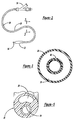
- the blended polymer materials of the present invention may be used to construct a centering balloon catheter for intravascular radiation therapy, which may be similar to that shown in Figures 6-10.
- the centering balloon catheter 10 may generally include a flexible catheter shaft 12 defining an inflation lumen 14, a proximal hub 16, and a centering balloon 18 at the distal end 20 of the catheter 10. The uniform effective radius of the centering balloon 18 provides the centering effect.
- a possible design for allowing such blood flow is to form the balloon in a spiral shape, as illustrated in figure 6.
- the smallest diameter portion of the spiral balloon is slightly larger than the outer diameter of the catheter shaft, yet the largest diameter portion of the spiral balloon 18 is large enough to contact the blood vessel wall.
- the resulting spiral channel will tend to allow blood flow in a spiral path from a position upstream of the balloon to a position downstream.
- a centering balloon prefferably has the following physical properties: relatively high flexibility; relatively low friction; capable of maintaining the desired spiral configuration when the balloon is pressurized; capable of being heat-bonded to the catheter shaft; and a tendency for the folds of the pleated balloon to refrain from sticking to each other, or tacking, during the processes of sterilization, shipping, or storage.
- the blended materials of the present invention can successfully meet all of these specifications and properties.
- centering balloons were made according to the following formula: 45 percent Rilsan® 67.33, 45 percent Grilamid® CF62BSE, and 10 percent Plexar® PX-209. These materials are available from the following suppliers: Rilsan from Atofina Chemicals in Philadelphia, Pennsylvania; Grilamid from EMS-CHEMIE in Charlotte, North Carolina, and Plexar from Equistar in Houston, Texas.
- This blended polymer made according to the principles of the present invention was tested and found to perform better than other commonly used polyamides and polyethylene. When formed into a balloon, the material is stronger, has a lower coefficient of friction, and a better spiral shape memory than polyethylene, PEBA, and has a flexibility similar to either of the copolyamides used to make the blended material.
- the melting temperatures of each constituent of a polymer of the present invention are believed to preferably be selected within approximately 30°C of each other.
- a catheter shaft can be enhanced by using the blended polymer materials of the present invention.
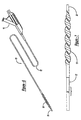
- a balloon catheter for intravascular angioplasty which may be similar to that shown in Figures 2-5.
- the balloon catheter 24 may generally include a flexible catheter shaft 26 defining an inflation lumen 28, a proximal hub 30, and a balloon 32 at the distal end 34 of the catheter.
- a proximal hub 30 defining an inflation lumen 28
- a proximal hub 30 defining an inflation lumen 28
- a balloon 32 at the distal end 34 of the catheter.
- many variations and other features are known in the art.
- a tubular inner body or guidewire tube 36 of a catheter shaft can be enhanced by using the blended polymer materials of the present invention, because it is desirable to form a tubular inner body or guidewire tube 36 of greater flexibility than is possible from a polyamide homopolymer alone. Moreover, the blended polymer materials of the present invention tend to exhibit less friction and more lubricity when advancing or withdrawing the catheter in a body passage, or when advancing or withdrawing a guidewire in a guidewire lumen defined by the catheter shaft.
- a single lumen or multiple lumen shaft member of the blended polymer materials of the present invention including forming a single lumen or multiple lumen shaft member of the blended polymer materials of the present invention.
- Another possible arrangement is combining a first shaft member made of a blended polymer material of the present invention with a second shaft member, perhaps made of another polymer or metal material.
- Yet another possible arrangement is to form a shaft member as a coextrusion of a blended polymer material of the present invention with another material.
- the materials and constituents of the present invention used for this Example of a balloon catheter shaft may of course preferably have the same features, specifications and properties, as the constituents from the same suppliers as in the first Example.
- microcatheter having a relatively low coefficient of friction, because many of the larger catheters may be made with materials having relatively high friction. Accordingly, it is desirable to form all or a portion of the shaft of a microcatheter of the blended polymer materials of the present invention.
- microcatheter shaft member as a coextrusion of a blended polymer material of the present invention with another material.
Abstract
Description
- The present invention relates generally to materials and methods for medical devices.
- A variety of polymers are used to make many different medical devices, including catheters, sheaths, grafts, balloons, catheter sheath introducers, and other medical devices used in the body of a patient. Such polymers used for medical devices include nylons, polyethylenes, polyesters, polyurethanes, and polyamides.
- Several desirable features for such polymers include in particular flexibility and low friction, as well as strength, the capability of being produced in a range of different flexibilities, and column stiffness.
- Of the polyamide materials, polyamide-12 in the form of a homopolymer has been used for a variety of medical devices, some types of which are referred to as nylon-12. Another material in the polyamide family that has been used includes polyamide-12 in a copolymer with other materials, including polyether block amide (PEBA). Also, polyamide-12 may be blended with PEBA to produce a material having a desired flexibility for a given application. However, PEBA generally has physical properties that are less than optimal for certain applications, including relatively high friction, a relatively high level of gels, and the absence of amide functional groups when the material is made with relatively high flexibility or low durometers.
- Another example is polyamide made in a coextrusion with high-density polyethylene (HDPE), which results in a multiple layer device. United States patent number 5,538,510 describes multilayer coextrusions of polyamides with high-density polyethylene. The resulting structure has relatively low friction on the high-density polyethylene layer, while the polyamide layer can be bonded to other polyamide materials by application of heat and pressure. It is desirable to develop such a material having these properties that is available for certain applications in a selective range of flexibilities.
- The materials of the present invention provide a unique combination of physical properties that are advantageous for use in medical devices for maneuvering through the circulatory system. The properties of high-strength, capability of bonding to other polyamides, and kink resistance are retained. In addition, several physical properties and benefits are provided by the materials of the present invention, including low friction, functional groups to bond to low friction surfaces, a range of flexibilities, and low gel counts.
- Accordingly, the materials of the present invention preferably include blends of polyamide and maleated polyethylene. The polyamide component of the blended materials of the present invention may of course include both homopolymers and copolymers, of which the copolymer is preferred.
- More particularly, this copolymer preferably uses disruption of the crystallinity of the polyamide to increase flexibility to a desired level. This method of increasing flexibility is in contrast to and more effective than PEBA, for example, which is also a copolymer. Instead of crystalline disruption, PEBA uses flexible linkages for flexibility.
- The other component of the polymers of the present invention, maleated polyethylene, is preferably HDPE, with the addition of the maleic anhydride.
- Preferably, the polyethylene component of the blended polymers of the present invention is as described in United States patent number 5,538,510, entitled "Catheter Having Coextruded Tubing," issued to Fontirroche, et al. on July 23, 1996, which is incorporated by reference. More specifically, the preferred polyethylene component of the blended polymer materials of the present invention is high-density polyethylene modified with maleic anhydride.
- As an example, the present invention will be described in relation to medical devices, and more particularly to medical catheters. However, it should be understood that the present invention relates to any apparatus or method having the features of the present invention, and is not limited to a particular material or type of design.
- These and various other objects, advantages and features of the invention will become apparent from the following description and claims, when considered in conjunction with the appended drawings.
-
- Figure 1 is an external perspective view of a catheter, arranged according to the principles of the present invention;
- Figure 2 is an external perspective view of a balloon catheter, arranged according to the principles of the present invention;
- Figure 3 is a transverse cross-sectional view of the balloon catheter of Figure 2, taken along line 3-3;
- Figure 4 is a longitudinal cross-sectional view of a balloon catheter, arranged according to the principles of the present invention;
- Figure 5 is a transverse cross-sectional view of the balloon catheter of Figure 4, taken along line 5-5;
- Figure 6 is an external perspective view of a centering balloon catheter, arranged according to the principles of the present invention; and
- Figure 7 is a partial elevational view of a portion of the centering balloon catheter of Figure 6;
- Figure 8 is an external perspective view of a centering balloon catheter according to the present invention; and
- Figures 9 and 10 are partial views of a portion of the centering balloon catheter of Figure 8.
-
- The following description of the preferred embodiments of the present invention is merely illustrative in nature, and as such it does not limit in any way the present invention, its application, or uses. Numerous modifications may be made by those skilled in the art without departing from the true spirit and scope of the invention.
- Referring to the drawings, several aspects of the present invention are depicted, with several of the preferred embodiments of the present invention being shown. The illustrated catheters are of course only examples of some of many different medical devices using the novel polymers within the scope of the present invention.
- The medical devices of the present invention incorporate a unique family of polymers including a polymer blend of polyamide and maleated polyethylene. These novel polymer blends present several advantageous features for medical devices, including flexibility and low friction, as well as strength, column stiffness, and the capability of being produced in a range of different flexibilities.
- The polyamide component of the blended materials of the present invention may of course include both homopolymers and copolymers, of which the copolymer is preferred. The other component of the present invention is preferably HDPE, with the addition of the maleic anhydride.
- A primary advantage of the present invention is the novel and unique combination of the following properties: flexibility, lubricity, and the compatibility of the various polymer constituents of the materials of the present invention. The term compatibility generally refers to the tendency of different polymer constituents to bond or heat-fuse with each other.
- Another primary advantage is increased lubricity, when compared with other flexible polyamides, and in particular when compared with PEBA.
- The blended polymer materials of the present invention may be used to construct a centering balloon catheter for intravascular radiation therapy, which may be similar to that shown in Figures 6-10. The centering
balloon catheter 10 may generally include aflexible catheter shaft 12 defining aninflation lumen 14, aproximal hub 16, and a centeringballoon 18 at thedistal end 20 of thecatheter 10. The uniform effective radius of the centeringballoon 18 provides the centering effect. - Many variations and other features are known in the art, including various polymer and metal materials, a guidewire lumen in a rapid-exchange or over-the-wire configuration, the catheter shaft having at least a portion made of metal hypotube, or the catheter shaft defining a single lumen, dual lumen or with a coaxial arrangement, etc. Another possible arrangement is to form a multiple layer balloon, with one of the layers being a blended polymer material of the present invention.
- It is also desirable to allow blood flow or perfusion between positions proximal and distal of the balloon, even while the balloon is inflated. A possible design for allowing such blood flow is to form the balloon in a spiral shape, as illustrated in figure 6. In such a spiral design, the smallest diameter portion of the spiral balloon is slightly larger than the outer diameter of the catheter shaft, yet the largest diameter portion of the
spiral balloon 18 is large enough to contact the blood vessel wall. When inflated, the resulting spiral channel will tend to allow blood flow in a spiral path from a position upstream of the balloon to a position downstream. - Other possible configurations for enabling perfusion of blood past the inflated balloon include a straight or contoured groove or channel, or an annular balloon shape, or a perfusion lumen defined by at least a portion of the catheter shaft.
- It is therefore desirable for a centering balloon to have the following physical properties: relatively high flexibility; relatively low friction; capable of maintaining the desired spiral configuration when the balloon is pressurized; capable of being heat-bonded to the catheter shaft; and a tendency for the folds of the pleated balloon to refrain from sticking to each other, or tacking, during the processes of sterilization, shipping, or storage.
- Depending upon the employed use, the blended materials of the present invention can successfully meet all of these specifications and properties. In this Example, centering balloons were made according to the following formula: 45 percent Rilsan® 67.33, 45 percent Grilamid® CF62BSE, and 10 percent Plexar® PX-209. These materials are available from the following suppliers: Rilsan from Atofina Chemicals in Philadelphia, Pennsylvania; Grilamid from EMS-CHEMIE in Charlotte, North Carolina, and Plexar from Equistar in Houston, Texas.
- This blended polymer made according to the principles of the present invention was tested and found to perform better than other commonly used polyamides and polyethylene. When formed into a balloon, the material is stronger, has a lower coefficient of friction, and a better spiral shape memory than polyethylene, PEBA, and has a flexibility similar to either of the copolyamides used to make the blended material.
- The melting temperatures of each constituent of a polymer of the present invention, Rilsan, Grilamid, and Plexar for example, are believed to preferably be selected within approximately 30°C of each other.
- A catheter shaft can be enhanced by using the blended polymer materials of the present invention. One particular example is a balloon catheter for intravascular angioplasty, which may be similar to that shown in Figures 2-5. The
balloon catheter 24 may generally include aflexible catheter shaft 26 defining aninflation lumen 28, aproximal hub 30, and aballoon 32 at thedistal end 34 of the catheter. As with the centering balloon catheter described above, many variations and other features are known in the art. - A tubular inner body or
guidewire tube 36 of a catheter shaft can be enhanced by using the blended polymer materials of the present invention, because it is desirable to form a tubular inner body orguidewire tube 36 of greater flexibility than is possible from a polyamide homopolymer alone. Moreover, the blended polymer materials of the present invention tend to exhibit less friction and more lubricity when advancing or withdrawing the catheter in a body passage, or when advancing or withdrawing a guidewire in a guidewire lumen defined by the catheter shaft. - Many variations are of course also possible, including forming a single lumen or multiple lumen shaft member of the blended polymer materials of the present invention. Another possible arrangement is combining a first shaft member made of a blended polymer material of the present invention with a second shaft member, perhaps made of another polymer or metal material. Yet another possible arrangement is to form a shaft member as a coextrusion of a blended polymer material of the present invention with another material.
- The materials and constituents of the present invention used for this Example of a balloon catheter shaft may of course preferably have the same features, specifications and properties, as the constituents from the same suppliers as in the first Example.
- The blended polymers of the present invention may also be used in small, relatively thin-walled interventional and diagnostic catheters called microcatheters, which may generally be used in neurological applications. Generally, such a microcatheter may be similar to that shown in Figure 1, having a
flexible catheter shaft 38 and a proximal hub 40. A relatively short distal segment of these catheters are preferably extremely flexible, and they are often guided through another larger catheter along a majority of the desired vascular path. - It is desirable to provide such a microcatheter having a relatively low coefficient of friction, because many of the larger catheters may be made with materials having relatively high friction. Accordingly, it is desirable to form all or a portion of the shaft of a microcatheter of the blended polymer materials of the present invention.
- Of course, many variations are also possible, including forming a microcatheter shaft member as a coextrusion of a blended polymer material of the present invention with another material.
- The materials and constituents of the present invention used for this Example of a microcatheter may of course preferably have the same features, specifications and properties, as the constituents from the same suppliers as in the first Example.
- It should be understood that an unlimited number of configurations for the present invention could be realized. The foregoing discussion describes merely exemplary embodiments illustrating the principles of the present invention, the scope of which is recited in the following claims. Those skilled in the art will readily recognize from the description, claims, and drawings that numerous changes and modifications can be made without departing from the spirit and scope of the invention.
Claims (10)
- A catheter, comprising a shaft member, at least a portion of the shaft member being made of a blend of polyamide and maleated polyethylene.
- A balloon catheter, comprising:a catheter shaft according to claim 1, said catheter shaft having a proximal and distal end, defining an inflation lumen; anda polymer balloon affixed to the catheter shaft near the distal end, the inflation lumen communicating with the balloon interior.
- The balloon catheter of claim 2, further comprising a guidewire lumen defined by and extending through at least a portion of the catheter shaft, the guidewire lumen having an inner wall surface being made of said polymer blend.
- The balloon catheter of claim 2 or claim 3, wherein at least a portion of the catheter shaft is formed of a multiple layer tube, at least one of the layers being made of said polymer blend.
- The balloon catheter of any of claims 2 to 4, further comprising a source-wire lumen defined by and extending through at least a portion of the catheter shaft, the source-wire lumen having a closed distal end near a distal end of the catheter; such that the balloon when inflated will tend to center the source-wire lumen distal end within a patient's body passage.
- The catheter of any preceding claim, wherein the polyamide component of the polymer blend is a homopolymer.
- The catheter of any of claims 1 to 5, wherein the polyamide component of the polymer blend is a copolymer.
- The catheter of any preceding claim, wherein the maleated polyethylene component of the polymer blend is a homopolymer with maleic anhydride.
- The catheter of any of claims 1 to 7, wherein the maleated polyethylene component of the polymer blend is HDPE with maleic anhydride.
- The catheter of any preceding claim, said polymer blend having functional groups capable of bonding to low friction surfaces.
Applications Claiming Priority (2)
| Application Number | Priority Date | Filing Date | Title |
|---|---|---|---|
| US736776 | 2000-12-14 | ||
| US09/736,776 US6547768B2 (en) | 2000-12-14 | 2000-12-14 | Medical devices with reduced friction polyamides, and method |
Publications (3)
| Publication Number | Publication Date |
|---|---|
| EP1219310A2 true EP1219310A2 (en) | 2002-07-03 |
| EP1219310A3 EP1219310A3 (en) | 2002-07-17 |
| EP1219310B1 EP1219310B1 (en) | 2004-07-07 |
Family
ID=24961261
Family Applications (1)
| Application Number | Title | Priority Date | Filing Date |
|---|---|---|---|
| EP01310443A Expired - Lifetime EP1219310B1 (en) | 2000-12-14 | 2001-12-13 | Catheters comprising reduced friction polyamides |
Country Status (5)
| Country | Link |
|---|---|
| US (1) | US6547768B2 (en) |
| EP (1) | EP1219310B1 (en) |
| JP (1) | JP4248782B2 (en) |
| AT (1) | ATE270560T1 (en) |
| DE (1) | DE60104186T2 (en) |
Cited By (1)
| Publication number | Priority date | Publication date | Assignee | Title |
|---|---|---|---|---|
| WO2005037337A1 (en) * | 2003-10-17 | 2005-04-28 | Invatec S.R.L. | Catheter balloons |
Families Citing this family (28)
| Publication number | Priority date | Publication date | Assignee | Title |
|---|---|---|---|---|
| US20020007145A1 (en) * | 1998-10-23 | 2002-01-17 | Timothy Stivland | Catheter having improved bonding region |
| US20030023261A1 (en) * | 2001-07-30 | 2003-01-30 | Scimed Life Systems Inc. | Chronic total occlusion device with variable stiffness shaft |
| US20040111108A1 (en) * | 2001-11-09 | 2004-06-10 | Farnan Robert C. | Balloon catheter with non-deployable stent |
| EP1441669B1 (en) | 2001-11-09 | 2009-03-25 | AngioScore, Inc. | Baloon catheter with non-deployable stent |
| US20030114831A1 (en) * | 2001-12-14 | 2003-06-19 | Scimed Life Systems, Inc. | Catheter having improved curve retention and method of manufacture |
| US6923787B2 (en) * | 2001-12-20 | 2005-08-02 | Scimed Life Systems, Inc. | Catheter having an improved balloon-to-catheter bond |
| US20050004515A1 (en) * | 2002-11-15 | 2005-01-06 | Hart Charles C. | Steerable kink resistant sheath |
| US8080026B2 (en) | 2003-01-21 | 2011-12-20 | Angioscore, Inc. | Apparatus and methods for treating hardened vascular lesions |
| US20050177130A1 (en) * | 2004-02-10 | 2005-08-11 | Angioscore, Inc. | Balloon catheter with spiral folds |
| DE602005023731D1 (en) * | 2004-07-29 | 2010-11-04 | Wilson Cook Medical Inc | Catheter shaft with separable wall |
| WO2006015323A2 (en) * | 2004-07-29 | 2006-02-09 | Wilson-Cook Medical Inc. | Catheter with splittable wall shaft and peel tool |
| US7897685B2 (en) * | 2004-12-07 | 2011-03-01 | E. I. Du Pont De Nemours And Company | Thermoplastic elastomer compositions |
| US10076641B2 (en) | 2005-05-11 | 2018-09-18 | The Spectranetics Corporation | Methods and systems for delivering substances into luminal walls |
| DK2279767T3 (en) * | 2005-07-18 | 2012-11-26 | Dentsply Ih Ab | Urinary catheter |
| US7901395B2 (en) * | 2005-08-16 | 2011-03-08 | Borden Jonathan R | Catheter having staggered lumens and method |
| JP2009519770A (en) | 2005-12-16 | 2009-05-21 | インターフェイス・アソシエイツ・インコーポレーテッド | Medical multilayer balloon and method for producing the same |
| DE102006003181A1 (en) * | 2006-01-23 | 2007-07-05 | Siemens Ag | Centering catheter has two sections whereby area between two sections consists of material transparent for light assigned with optical coherence tomography or photo-dynamic therapy and second section is expandable by pressure application |
| US9265918B2 (en) | 2008-09-03 | 2016-02-23 | Boston Scientific Scimed, Inc. | Multilayer medical balloon |
| SE532941C2 (en) * | 2008-09-15 | 2010-05-18 | Phasein Ab | Gas sampling line for breathing gases |
| US8632559B2 (en) | 2010-09-21 | 2014-01-21 | Angioscore, Inc. | Method and system for treating valve stenosis |
| US8821478B2 (en) | 2011-03-04 | 2014-09-02 | Boston Scientific Scimed, Inc. | Catheter with variable stiffness |
| US8951296B2 (en) * | 2012-06-29 | 2015-02-10 | Medtronic Ardian Luxembourg S.A.R.L. | Devices and methods for photodynamically modulating neural function in a human |
| US10117668B2 (en) | 2013-10-08 | 2018-11-06 | The Spectranetics Corporation | Balloon catheter with non-deployable stent having improved stability |
| US10780246B2 (en) | 2014-09-12 | 2020-09-22 | Callisyn Biomedical, Inc. | Vascular microcatheter |
| JP1557903S (en) * | 2016-02-12 | 2016-09-05 | ||
| DE102016106478A1 (en) * | 2016-04-08 | 2017-10-12 | Biotronik Ag | Device for emitting energy and / or measuring electrical activity |
| USD838845S1 (en) * | 2017-02-07 | 2019-01-22 | Tata Consultancy Services Lmited | Ultrasound tidal breathing sensor pipe |
| US11285245B2 (en) | 2018-02-09 | 2022-03-29 | C.R. Bard, Inc. | Medical devices including functionalized polymers and related methods |
Citations (2)
| Publication number | Priority date | Publication date | Assignee | Title |
|---|---|---|---|---|
| US5814384A (en) * | 1994-06-17 | 1998-09-29 | Alliedsignal, Inc. | Articles of manufacture comprising extruded polyamide-low density polyethylene graft blends |
| US5820594A (en) * | 1994-01-31 | 1998-10-13 | Cordis Corporation | Balloon catheter |
Family Cites Families (23)
| Publication number | Priority date | Publication date | Assignee | Title |
|---|---|---|---|---|
| IT1095574B (en) | 1978-04-12 | 1985-08-10 | Snam Progetti | PROCEDURE FOR THE PREPARATION OF BIOCOMPATIBLE MATERIALS OF A POLYAMIDE NATURE AND MANUFACTURES SO OBTAINED |
| US4762130A (en) * | 1987-01-15 | 1988-08-09 | Thomas J. Fogarty | Catheter with corkscrew-like balloon |
| US4898591A (en) | 1988-08-09 | 1990-02-06 | Mallinckrodt, Inc. | Nylon-PEBA copolymer catheter |
| US5433713A (en) * | 1991-04-15 | 1995-07-18 | Cordis Corporation | Polyetheramide tubing for medical devices |
| US5403339A (en) | 1991-06-21 | 1995-04-04 | Terumo Kabushiki Kaisha | Blood vessel dilator |
| JP2627988B2 (en) | 1991-08-21 | 1997-07-09 | 三菱電線工業株式会社 | Method and apparatus for manufacturing rigid inclined long body |
| EP0569263B1 (en) * | 1992-04-06 | 1997-07-02 | Terumo Kabushiki Kaisha | Balloon catheter |
| US5370615A (en) | 1992-12-28 | 1994-12-06 | Cordis Corporation | Balloon catheter for angioplasty |
| US5921957A (en) | 1994-07-12 | 1999-07-13 | Scimed Life Systems, Inc. | Intravascular dilation catheter |
| US5849846A (en) * | 1994-07-25 | 1998-12-15 | Advanced Cardiovascular Systems, Inc. | Balloons for medical catheters |
| US6325790B1 (en) | 1995-04-11 | 2001-12-04 | Cordis Corporation | Soft tip catheter |
| CA2219744A1 (en) | 1995-05-24 | 1996-11-28 | Schneider (Usa) Inc. | Dilatation balloons containing polyesteretheramide copolymer |
| DE69723137T2 (en) | 1996-03-18 | 2004-05-27 | Ashiya, Hiroaki | Catheteranordnung |
| US6123712A (en) * | 1996-08-23 | 2000-09-26 | Scimed Life Systems, Inc. | Balloon catheter with stent securement means |
| US5797948A (en) * | 1996-10-03 | 1998-08-25 | Cordis Corporation | Centering balloon catheter |
| US6159187A (en) | 1996-12-06 | 2000-12-12 | Target Therapeutics, Inc. | Reinforced catheter with a formable distal tip |
| JP3527378B2 (en) | 1997-01-31 | 2004-05-17 | テルモ株式会社 | Contrast catheter |
| US6165166A (en) * | 1997-04-25 | 2000-12-26 | Schneider (Usa) Inc. | Trilayer, extruded medical tubing and medical devices incorporating such tubing |
| US6093463A (en) * | 1997-12-12 | 2000-07-25 | Intella Interventional Systems, Inc. | Medical devices made from improved polymer blends |
| US6036670A (en) | 1997-12-23 | 2000-03-14 | Cordis Corporation | Coiled transition balloon catheter, assembly and procedure |
| US6033380A (en) * | 1998-02-13 | 2000-03-07 | Cordis Corporation | Six-pleated catheter balloon and device for forming same |
| US6086970A (en) * | 1998-04-28 | 2000-07-11 | Scimed Life Systems, Inc. | Lubricious surface extruded tubular members for medical devices |
| US6428552B1 (en) | 2001-01-22 | 2002-08-06 | Lumend, Inc. | Method and apparatus for crossing intravascular occlusions |
-
2000
- 2000-12-14 US US09/736,776 patent/US6547768B2/en not_active Expired - Lifetime
-
2001
- 2001-12-13 AT AT01310443T patent/ATE270560T1/en not_active IP Right Cessation
- 2001-12-13 EP EP01310443A patent/EP1219310B1/en not_active Expired - Lifetime
- 2001-12-13 DE DE60104186T patent/DE60104186T2/en not_active Expired - Lifetime
- 2001-12-14 JP JP2001382052A patent/JP4248782B2/en not_active Expired - Lifetime
Patent Citations (2)
| Publication number | Priority date | Publication date | Assignee | Title |
|---|---|---|---|---|
| US5820594A (en) * | 1994-01-31 | 1998-10-13 | Cordis Corporation | Balloon catheter |
| US5814384A (en) * | 1994-06-17 | 1998-09-29 | Alliedsignal, Inc. | Articles of manufacture comprising extruded polyamide-low density polyethylene graft blends |
Cited By (2)
| Publication number | Priority date | Publication date | Assignee | Title |
|---|---|---|---|---|
| WO2005037337A1 (en) * | 2003-10-17 | 2005-04-28 | Invatec S.R.L. | Catheter balloons |
| US8268418B2 (en) | 2003-10-17 | 2012-09-18 | Medtronic, Inc. | Catheter balloons |
Also Published As
| Publication number | Publication date |
|---|---|
| DE60104186T2 (en) | 2005-08-04 |
| US20020077606A1 (en) | 2002-06-20 |
| ATE270560T1 (en) | 2004-07-15 |
| EP1219310A3 (en) | 2002-07-17 |
| DE60104186D1 (en) | 2004-08-12 |
| JP2002315822A (en) | 2002-10-29 |
| EP1219310B1 (en) | 2004-07-07 |
| US6547768B2 (en) | 2003-04-15 |
| JP4248782B2 (en) | 2009-04-02 |
Similar Documents
| Publication | Publication Date | Title |
|---|---|---|
| EP1219310B1 (en) | Catheters comprising reduced friction polyamides | |
| US5820594A (en) | Balloon catheter | |
| EP1596898B1 (en) | Balloon catheter | |
| US6277093B1 (en) | Lubricious and readily bondable catheter shaft | |
| AU638936B2 (en) | Nylon-peba copolymer catheter | |
| JP4666882B2 (en) | Catheter shaft having a layer of varying thickness and method for manufacturing the same | |
| US6217547B1 (en) | Lubricous and readily bondable catheter shaft | |
| AU2007276967B2 (en) | Catheter components formed of a compound of polymer with particles or fibers | |
| US7341571B1 (en) | Balloon catheter having a multilayered distal tip | |
| US6443925B1 (en) | Balloon catheter shaft formed of liquid crystal polymeric material blend | |
| EP2437800A2 (en) | Robust cathether tubing comprising nylon | |
| US5569196A (en) | Trackable intravascular catheter | |
| US7273487B1 (en) | Balloon catheter having a multilayered shaft with variable flexibility | |
| US8012123B2 (en) | Catheter with guidewire lumen with tubular portion and sleeve | |
| JP4833039B2 (en) | catheter | |
| JP4914282B2 (en) | Catheter with pushability | |
| JP2008264119A (en) | Catheter with pressing property | |
| CA2420626C (en) | Catheter having coextruded tubing |
Legal Events
| Date | Code | Title | Description |
|---|---|---|---|
| PUAI | Public reference made under article 153(3) epc to a published international application that has entered the european phase |
Free format text: ORIGINAL CODE: 0009012 |
|
| PUAL | Search report despatched |
Free format text: ORIGINAL CODE: 0009013 |
|
| AK | Designated contracting states |
Kind code of ref document: A2 Designated state(s): AT BE CH CY DE DK ES FI FR GB GR IE IT LI LU MC NL PT SE TR |
|
| AX | Request for extension of the european patent |
Free format text: AL;LT;LV;MK;RO;SI |
|
| AK | Designated contracting states |
Kind code of ref document: A3 Designated state(s): AT BE CH CY DE DK ES FI FR GB GR IE IT LI LU MC NL PT SE TR |
|
| AX | Request for extension of the european patent |
Free format text: AL;LT;LV;MK;RO;SI |
|
| 17P | Request for examination filed |
Effective date: 20030107 |
|
| AKX | Designation fees paid |
Designated state(s): AT BE CH CY DE DK ES FI FR GB GR IE IT LI LU MC NL PT SE TR |
|
| 17Q | First examination report despatched |
Effective date: 20030414 |
|
| GRAP | Despatch of communication of intention to grant a patent |
Free format text: ORIGINAL CODE: EPIDOSNIGR1 |
|
| GRAS | Grant fee paid |
Free format text: ORIGINAL CODE: EPIDOSNIGR3 |
|
| GRAA | (expected) grant |
Free format text: ORIGINAL CODE: 0009210 |
|
| AK | Designated contracting states |
Kind code of ref document: B1 Designated state(s): AT BE CH CY DE DK ES FI FR GB GR IE IT LI LU MC NL PT SE TR |
|
| PG25 | Lapsed in a contracting state [announced via postgrant information from national office to epo] |
Ref country code: CH Free format text: LAPSE BECAUSE OF FAILURE TO SUBMIT A TRANSLATION OF THE DESCRIPTION OR TO PAY THE FEE WITHIN THE PRESCRIBED TIME-LIMIT Effective date: 20040707 Ref country code: AT Free format text: LAPSE BECAUSE OF FAILURE TO SUBMIT A TRANSLATION OF THE DESCRIPTION OR TO PAY THE FEE WITHIN THE PRESCRIBED TIME-LIMIT Effective date: 20040707 Ref country code: TR Free format text: LAPSE BECAUSE OF FAILURE TO SUBMIT A TRANSLATION OF THE DESCRIPTION OR TO PAY THE FEE WITHIN THE PRESCRIBED TIME-LIMIT Effective date: 20040707 Ref country code: CY Free format text: LAPSE BECAUSE OF FAILURE TO SUBMIT A TRANSLATION OF THE DESCRIPTION OR TO PAY THE FEE WITHIN THE PRESCRIBED TIME-LIMIT Effective date: 20040707 Ref country code: FI Free format text: LAPSE BECAUSE OF FAILURE TO SUBMIT A TRANSLATION OF THE DESCRIPTION OR TO PAY THE FEE WITHIN THE PRESCRIBED TIME-LIMIT Effective date: 20040707 Ref country code: LI Free format text: LAPSE BECAUSE OF FAILURE TO SUBMIT A TRANSLATION OF THE DESCRIPTION OR TO PAY THE FEE WITHIN THE PRESCRIBED TIME-LIMIT Effective date: 20040707 |
|
| REG | Reference to a national code |
Ref country code: GB Ref legal event code: FG4D |
|
| REG | Reference to a national code |
Ref country code: CH Ref legal event code: EP |
|
| REG | Reference to a national code |
Ref country code: IE Ref legal event code: FG4D |
|
| REF | Corresponds to: |
Ref document number: 60104186 Country of ref document: DE Date of ref document: 20040812 Kind code of ref document: P |
|
| PG25 | Lapsed in a contracting state [announced via postgrant information from national office to epo] |
Ref country code: SE Free format text: LAPSE BECAUSE OF FAILURE TO SUBMIT A TRANSLATION OF THE DESCRIPTION OR TO PAY THE FEE WITHIN THE PRESCRIBED TIME-LIMIT Effective date: 20041007 Ref country code: GR Free format text: LAPSE BECAUSE OF FAILURE TO SUBMIT A TRANSLATION OF THE DESCRIPTION OR TO PAY THE FEE WITHIN THE PRESCRIBED TIME-LIMIT Effective date: 20041007 Ref country code: DK Free format text: LAPSE BECAUSE OF FAILURE TO SUBMIT A TRANSLATION OF THE DESCRIPTION OR TO PAY THE FEE WITHIN THE PRESCRIBED TIME-LIMIT Effective date: 20041007 |
|
| PG25 | Lapsed in a contracting state [announced via postgrant information from national office to epo] |
Ref country code: ES Free format text: LAPSE BECAUSE OF FAILURE TO SUBMIT A TRANSLATION OF THE DESCRIPTION OR TO PAY THE FEE WITHIN THE PRESCRIBED TIME-LIMIT Effective date: 20041018 |
|
| PG25 | Lapsed in a contracting state [announced via postgrant information from national office to epo] |
Ref country code: LU Free format text: LAPSE BECAUSE OF NON-PAYMENT OF DUE FEES Effective date: 20041213 |
|
| PG25 | Lapsed in a contracting state [announced via postgrant information from national office to epo] |
Ref country code: MC Free format text: LAPSE BECAUSE OF NON-PAYMENT OF DUE FEES Effective date: 20041231 |
|
| REG | Reference to a national code |
Ref country code: CH Ref legal event code: PL |
|
| ET | Fr: translation filed | ||
| PLBE | No opposition filed within time limit |
Free format text: ORIGINAL CODE: 0009261 |
|
| STAA | Information on the status of an ep patent application or granted ep patent |
Free format text: STATUS: NO OPPOSITION FILED WITHIN TIME LIMIT |
|
| 26N | No opposition filed |
Effective date: 20050408 |
|
| PG25 | Lapsed in a contracting state [announced via postgrant information from national office to epo] |
Ref country code: PT Free format text: LAPSE BECAUSE OF NON-PAYMENT OF DUE FEES Effective date: 20041207 |
|
| REG | Reference to a national code |
Ref country code: FR Ref legal event code: PLFP Year of fee payment: 16 |
|
| PG25 | Lapsed in a contracting state [announced via postgrant information from national office to epo] |
Ref country code: IT Free format text: LAPSE BECAUSE OF NON-PAYMENT OF DUE FEES Effective date: 20151213 |
|
| PGFP | Annual fee paid to national office [announced via postgrant information from national office to epo] |
Ref country code: IE Payment date: 20161229 Year of fee payment: 16 Ref country code: GB Payment date: 20161228 Year of fee payment: 16 Ref country code: NL Payment date: 20161226 Year of fee payment: 16 |
|
| PGFP | Annual fee paid to national office [announced via postgrant information from national office to epo] |
Ref country code: FR Payment date: 20161227 Year of fee payment: 16 |
|
| PGFP | Annual fee paid to national office [announced via postgrant information from national office to epo] |
Ref country code: DE Payment date: 20161229 Year of fee payment: 16 |
|
| PGFP | Annual fee paid to national office [announced via postgrant information from national office to epo] |
Ref country code: BE Payment date: 20161227 Year of fee payment: 16 |
|
| PG25 | Lapsed in a contracting state [announced via postgrant information from national office to epo] |
Ref country code: IT Free format text: LAPSE BECAUSE OF NON-PAYMENT OF DUE FEES Effective date: 20151213 |
|
| PGFP | Annual fee paid to national office [announced via postgrant information from national office to epo] |
Ref country code: IT Payment date: 20161222 Year of fee payment: 16 |
|
| PGRI | Patent reinstated in contracting state [announced from national office to epo] |
Ref country code: IT Effective date: 20170710 |
|
| REG | Reference to a national code |
Ref country code: DE Ref legal event code: R119 Ref document number: 60104186 Country of ref document: DE |
|
| REG | Reference to a national code |
Ref country code: GB Ref legal event code: 732E Free format text: REGISTERED BETWEEN 20180614 AND 20180620 |
|
| REG | Reference to a national code |
Ref country code: NL Ref legal event code: MM Effective date: 20180101 |
|
| GBPC | Gb: european patent ceased through non-payment of renewal fee |
Effective date: 20171213 |
|
| REG | Reference to a national code |
Ref country code: IE Ref legal event code: MM4A |
|
| PG25 | Lapsed in a contracting state [announced via postgrant information from national office to epo] |
Ref country code: NL Free format text: LAPSE BECAUSE OF NON-PAYMENT OF DUE FEES Effective date: 20180101 |
|
| REG | Reference to a national code |
Ref country code: FR Ref legal event code: ST Effective date: 20180831 |
|
| REG | Reference to a national code |
Ref country code: BE Ref legal event code: MM Effective date: 20171231 |
|
| PG25 | Lapsed in a contracting state [announced via postgrant information from national office to epo] |
Ref country code: IE Free format text: LAPSE BECAUSE OF NON-PAYMENT OF DUE FEES Effective date: 20171213 Ref country code: DE Free format text: LAPSE BECAUSE OF NON-PAYMENT OF DUE FEES Effective date: 20180703 Ref country code: FR Free format text: LAPSE BECAUSE OF NON-PAYMENT OF DUE FEES Effective date: 20180102 Ref country code: IT Free format text: LAPSE BECAUSE OF NON-PAYMENT OF DUE FEES Effective date: 20171213 |
|
| PG25 | Lapsed in a contracting state [announced via postgrant information from national office to epo] |
Ref country code: BE Free format text: LAPSE BECAUSE OF NON-PAYMENT OF DUE FEES Effective date: 20171231 Ref country code: GB Free format text: LAPSE BECAUSE OF NON-PAYMENT OF DUE FEES Effective date: 20171213 |