EP1225565A2 - Sound controller that generates sound responsive to a situation - Google Patents
Sound controller that generates sound responsive to a situation Download PDFInfo
- Publication number
- EP1225565A2 EP1225565A2 EP01130354A EP01130354A EP1225565A2 EP 1225565 A2 EP1225565 A2 EP 1225565A2 EP 01130354 A EP01130354 A EP 01130354A EP 01130354 A EP01130354 A EP 01130354A EP 1225565 A2 EP1225565 A2 EP 1225565A2
- Authority
- EP
- European Patent Office
- Prior art keywords
- sound
- sound source
- channel
- output
- information
- Prior art date
- Legal status (The legal status is an assumption and is not a legal conclusion. Google has not performed a legal analysis and makes no representation as to the accuracy of the status listed.)
- Withdrawn
Links
Images


Classifications
-
- G—PHYSICS
- G10—MUSICAL INSTRUMENTS; ACOUSTICS
- G10H—ELECTROPHONIC MUSICAL INSTRUMENTS; INSTRUMENTS IN WHICH THE TONES ARE GENERATED BY ELECTROMECHANICAL MEANS OR ELECTRONIC GENERATORS, OR IN WHICH THE TONES ARE SYNTHESISED FROM A DATA STORE
- G10H1/00—Details of electrophonic musical instruments
- G10H1/46—Volume control
-
- G—PHYSICS
- G10—MUSICAL INSTRUMENTS; ACOUSTICS
- G10H—ELECTROPHONIC MUSICAL INSTRUMENTS; INSTRUMENTS IN WHICH THE TONES ARE GENERATED BY ELECTROMECHANICAL MEANS OR ELECTRONIC GENERATORS, OR IN WHICH THE TONES ARE SYNTHESISED FROM A DATA STORE
- G10H2210/00—Aspects or methods of musical processing having intrinsic musical character, i.e. involving musical theory or musical parameters or relying on musical knowledge, as applied in electrophonic musical tools or instruments
- G10H2210/021—Background music, e.g. for video sequences, elevator music
- G10H2210/026—Background music, e.g. for video sequences, elevator music for games, e.g. videogames
-
- G—PHYSICS
- G10—MUSICAL INSTRUMENTS; ACOUSTICS
- G10H—ELECTROPHONIC MUSICAL INSTRUMENTS; INSTRUMENTS IN WHICH THE TONES ARE GENERATED BY ELECTROMECHANICAL MEANS OR ELECTRONIC GENERATORS, OR IN WHICH THE TONES ARE SYNTHESISED FROM A DATA STORE
- G10H2250/00—Aspects of algorithms or signal processing methods without intrinsic musical character, yet specifically adapted for or used in electrophonic musical processing
- G10H2250/541—Details of musical waveform synthesis, i.e. audio waveshape processing from individual wavetable samples, independently of their origin or of the sound they represent
- G10H2250/571—Waveform compression, adapted for music synthesisers, sound banks or wavetables
- G10H2250/591—DPCM [delta pulse code modulation]
- G10H2250/595—ADPCM [adaptive differential pulse code modulation]
Definitions
- the present invention relates to a sound controller, a sound control method, a sound control program to be executed on a computer, a computer-readable storage medium having stored therein the sound control program, and a program execution apparatus for executing the sound control program, all of which are preferably applicable to a video game machine or an entertainment system having video game functions.
- Video game machines which execute a video game based on a game program stored in a storage medium such as a CD-ROM, DVD-ROM or semiconductor memory are currently in widespread use.
- background music as a main theme song of the game is formed, such background music being output from, for example, a speaker unit of a television receiver. It is thus possible to enjoy the operation of characters and the like in a video game while listening to the background music.
- a sound controller in consideration of the above-noted problems in the conventional art, to provide a sound controller, a sound control method, a a computer program product, in the following also referred to as a sound control program to be executed on a computer, a computer-readable storage medium having stored therein the sound control program, and a program execution apparatus for executing the sound control program, all of which enable generation of sound that effectively portrays the drama of each scene in a video game.
- sound source information of each channel is reproduced, based on sequence information that controls the sound source reproducing operation on each channel, and the output level of the reproduced sound source information is adjusted, responsive to at least scene or situation.
- the present invention can be applied to an entertainment system having video game functions as shown in Fig. 1.
- This entertainment system has a main unit 1 and a controller 2 connected to the main unit 1.
- the main unit 1 has a disk tray 3, on which an optical disk such as a CD-ROM or DVD-ROM having stored therein a video game program, sound information such as sound of a character or effective sound, and music information such as a background music (BGM) for the video game is loaded, and a reset button 4 for specifying reset and the like of the operation of the main unit 1.
- an optical disk such as a CD-ROM or DVD-ROM having stored therein a video game program
- sound information such as sound of a character or effective sound
- music information such as a background music (BGM) for the video game is loaded
- BGM background music
- the main unit 1 has two USB (Universal Serial Bus) connectors 5, an IEEE (Institute of Electrical and Electronics Engineers) 1394 connector 6, controller ports 7A and 7B to which the controllers 2 are connected, memory card slots 8A and 8B into which memory cards 26 for storing game contents up to the point at which playing of a video game was interrupted are inserted, and an eject button 9 for specifying ejection of the optical disk loaded on the disk tray 3.
- USB Universal Serial Bus
- IEEE Institute of Electrical and Electronics Engineers 1394 connector 6
- controller ports 7A and 7B to which the controllers 2 are connected
- memory card slots 8A and 8B into which memory cards 26 for storing game contents up to the point at which playing of a video game was interrupted are inserted
- an eject button 9 for specifying ejection of the optical disk loaded on the disk tray 3.
- the main unit 1 is provide on its rear panel with a power switch, an audio/video output terminal (AV multi-output terminal), a PC card slot, an optical digital output terminal, and an AC line input terminal or the like.
- a television receiver 10 used as a monitor is connected to the main unit 1 via the AV multi-output terminal, so that it not only displays a game screen of the video game, but also outputs through a speaker units 11 thereof sounds of a character, effective sound or background music, of the video game.
- the controller 2 has a left grip 35 gripped and held within the palm of the left hand of the player, a right grip 36 gripped and held within the palm of the right hand of the player, a left operating part 21 and a right operating part 22, which are each operated by the thumbs of the left and right hands, respectively, while the grips 35 and 36 being gripped by the left and right hands of the player, respectively, a left analog operating part 31 and a right analog operating part 32, which have joysticks enabling analog operation (joystick operation) by the left and right thumbs, a first left pushbutton 23L and a first right pushbutton 23R, which are operated by pressing by the left and right index fingers, respectively, and a second left pushbutton and a second right pushbutton (not shown), which are provided below the first left and right pushbuttons 23L and 23R, respectively, and which are operated by the middle fingers of the left and right hands, respectively.
- the above-noted left operating part 21 is provided with “up”, “down”, “left” and “right” direction keys, used, for example, when a player moves a character, for example, to up, down, left, and right directions respectively on the screen.
- the "up”, “down”, “left” and “right” direction keys are used not only to issue “up”, “down”, “left” and “right” direction commands, but can also be used for issuing commands for an oblique direction. For example, if the "up” key and the "right” key are pressed simultaneously, it is possible to issue a command for the upper-right direction. The same is true of the other direction keys. For example, if the "down" direction key and the "left” direction key are pressed simultaneously, a command is given for the lower-left direction.
- the right operating part 22 has four command buttons (these buttons being respectively marked by engraved ⁇ , ⁇ , ⁇ , and o marks), to which different functions are assigned by a game application program.
- the above-noted joysticks are capable of precession in response to analog operations by the left and right analog operating parts 31 and 32.
- the position thereof is held in the vertical attitude (reference position) condition in which they are not inclined from the vertical, and when they are operated so as to impart an inclination thereto, coordinate values on an X-Y coordinate are detected based on the amount of inclination with respect to the reference position and the direction of the inclination, such detected coordinate values being supplied to the main unit 1 as the operation output.
- the controller 2 is further provided with a mode selection button 33 for switching between the analog operating mode and the digital operating mode, a light indicator 34 for notifying a player, for example by lightning of an LED (light-emitting diode) or the like, of the operating mode selected by the mode selection button 33, a start button 24 for giving commands for starting, pausing or reproducing a game, and a select button 25 for instructing display of a menu or the operating panel on the television receiver 11.
- a mode selection button 33 for switching between the analog operating mode and the digital operating mode
- a light indicator 34 for notifying a player, for example by lightning of an LED (light-emitting diode) or the like, of the operating mode selected by the mode selection button 33
- a start button 24 for giving commands for starting, pausing or reproducing a game
- a select button 25 for instructing display of a menu or the operating panel on the television receiver 11.
- the mode selection button 33 When the mode selection button 33 is used to select the analog operating mode, the light indicator 34 is controlled so as to light, and the left and right analog operating parts 31 and 32 are activated. When the digital operating mode is selected, the light indicator 34 is extinguished and operation of the left and right analog operating parts 31 and 32 are deactivated.
- the controller 2 is provided within the left grip 35 and the right grip 36 with a vibration generating mechanism which generates a vibration, for example by causing a weight that is eccentrically disposed with respect to a motor to rotate, thereby enabling operation of the vibration generating mechanism in response to a command from the main unit 1 when a character being damaged, for example.
- a vibration generating mechanism which generates a vibration, for example by causing a weight that is eccentrically disposed with respect to a motor to rotate, thereby enabling operation of the vibration generating mechanism in response to a command from the main unit 1 when a character being damaged, for example.
- the controller 2 When the various buttons and operating parts provided on the controller 2 are operated by the player, the controller 2 generates an operating signal corresponding to the operation, such operating signal being supplied to the main unit 1 via a cable 13 and a controller connecting portion 12.
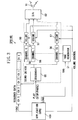
- the main unit 1 has a main CPU 100 for performing signal processing and control of internal constituent elements, based on various programs such as a game application program, a graphic processing unit (GPU) 110 for performing image processing, an IO processor (IOP) 120 for performing interface processing between the main unit 1 and an external device such as the controller 2 and the memory card 26 or the like, a mechanical controller 190 for performing reproduction control of the optical disk 130 such as a DVD-ROM or CD-ROM onto which an application program or multi-media data is stored, a main memory (RAM) 160 which includes functions as a working area for the main CPU 100 and a buffer for temporary storing data read out from the optical disk 130, a MASK-ROM 150 into which an operating system program executed by the main CPU 100 or the IOP 120 is mainly stored, and a sound processor unit (SPU) 140 for performing audio signal processing.
- a main CPU 100 for performing signal processing and control of internal constituent elements, based on various programs such as a game application program
- GPU graphic processing unit
- IOP IO processor
- the main unit 1 has a CD/DVD digital signal processor 170 (DSP) responsible for error correction processing (CIRC processing) of reproduction output from the optical disk 130 supplied via an RF amplifier 131, and responsible for expanding and decoding processing of compressed coded data; a driver 180 and the mechanical controller 190 for controlling rotation of a spindle motor 132, focus and tracking control of an optical pickup 133, and loading control of the disk tray; and a card-type connector (PC card slot) 200 for connecting, for example, a communication card or an external hard disk drive or the like.
- DSP CD/DVD digital signal processor 170
- CIRC processing error correction processing
- PC card slot PC card slot
- bus lines 202 and 203 are mutually connected via bus lines 202 and 203 or the like.
- the connection between the main CPU 100 and the graphic processor 110 is made by a dedicated bus line, and the connection between the main CPU 100 and the IOP 120 is made by a sub-bus SBUS.
- the IOP 120 is connected to the CD/DVD digital signal processor 170, the MASK-ROM 150, the sound processor unit (SPU) 140, and the card-type connector 200 by an SBUS.
- the main CPU 100 by executing an operating system program for the main CPU stored in the MASK-ROM 150, controls the overall operation of the main unit 1.
- the main CPU 100 by executing various application programs read out from the optical disk 130 and loaded into the main memory 160, or by executing various application programs downloaded via a communication network, also controls the operation of a video game in the main unit 1.
- the IOP 120 by executing an operating system program therefor stored in the MASK-ROM 150, performs such tasks as input/output of a signal sent from the controller 2 in response to operation by a player and data sent from the memory card 26 for storing game settings, in addition to control of input/output of data at a USB connector (not shown), at an IEEE 1394 connector, or at a PC card slot or the like, and data protocol conversion.
- the MASK-ROM 150 can store device IDs for the controllers 2 connected to the controller ports 7A and 7B, the memory cards 26 connected to the memory card slots 8A and 8B, and PC cards and the like connected to the card-type connector (PC card slot) 200, and the IOP 200 performs communication with devices such as the above-noted controllers 2, the memory cards 26 or the like, in accordance with such device IDs, to thereby specify the external devices such as the controller 2 or the memory card or the like, which are connected to the main unit 1.
- the graphic processor unit 110 performs drawing in accordance with drawing instructions from the main CPU 100, and stores drawn images in a frame buffer (not shown) .
- the graphic processor unit 110 also has a function as a geometry transfer engine responsible for processing such as coordinate transfer.
- the graphic processor unit 110 in serving as a geometry transfer engine, in the case in which an application program such as a video game stored in the optical disk 130 uses so-called three-dimensional (3D) graphics, constructs virtual three-dimensional objects which are formed by a set of triangular polygons.
- the graphic processor unit 110 also performs various calculations for generating an image possibly obtained by photographing such three-dimensional object with a virtual camera, that is, the perspective conversion for rendering (calculations of coordinate value for the case in which the vertices of each polygon making up a three-dimensional object are projected onto a virtual screen).
- the graphic processor unit 110 in accordance with drawing instructions from the main CPU 100, performs rendering of three-dimensional objects to generate an image with respect to the frame buffer while making use, if necessary, of the geometry transfer engine.
- the graphic processor unit 110 outputs a video signal responsive to such generated images.
- the sound processor unit 140 has an ADPCM decoding function for reproducing sound data which were processed by adaptive predictive coding, a reproducing function for reproducing and outputting audio signals such as effective sound or the like by reproducing waveform data stored in a sound buffer built in such unit 140 or externally attached thereto, and a modulation function for modulating and reproducing the waveform data stored in the sound buffer.
- the sound processor unit 140 thus provided with such functions can be used as a so-called sampling sound source, which can generate audio signals of music sound and effective sound and the like from the waveform data stored in the sound buffer, based on instructions from the CPU 100.
- an operating system program for the main CPU and an operating system program for the IOP are each read out from the MASK-ROM 150, the main CPU 100 and the IOP 120 executing each corresponding operating system program.
- the main CPU 100 performs overall control of the main unit 1, and the IOP 120 performs input/output signal control between the controller 2 and the memory card 26 or the like.
- the main CPU 100 executes its operating system program, after performing initialization processing such as a verification of operation, it reads out an application program for a game or the like recorded on the optical disk 130 and, after loading the program in the main memory 160, then executes such program.
- the main CPU 100 controls the graphic processor unit 110 and the sound processor unit 140, responsive to player's commands input by a controller 2 via the IOP 120, so as to perform control of image display, effective sound, and music (background music).
- the entertainment system controls the sound processor unit 140 so as to control the generation of effective sound or background music, thereby providing sounds appropriate to each scene of the video game.
- Fig. 3 is a functional block diagram showing the concept of the sound processor unit 140, from which drawing it can be seen that the sound processor unit 140 has a sound driver 50, a tone generator 51, and a D/A converter 52.
- the sound driver 50 has a sequencer 55 for controlling sound generation of sound source data, based on sequence data such as MIDI (Musical Instrument Digital Interface) data or the like, a plurality of sound source reproducing channels 56(Channel 0 to Channel 15 in Fig. 3) for reproducing sound source data (VAB) supplied from the tone generator 51 under control of the sequencer 55, a plurality of volume controllers 57 for performing volume control of the reproduction output of such reproduced sound source data, and a D/A converter 52 for converting the reproduction output of the sound source data from the volume controllers 57 to analog form and supplies same, for example, to a speaker units 11 of a television receiver 10.
- sequence data such as MIDI (Musical Instrument Digital Interface) data or the like
- VAB sound source data supplied from the tone generator 51 under control of the sequencer 55
- VAB sound source data supplied from the tone generator 51 under control of the sequencer 55
- VAB sound source data supplied from the tone generator 51 under control of the sequencer 55
- volume controllers 57 for performing
- the sound source data reproduced by each of the sound source reproducing channels 56 is usually output at predetermined volume level for each channel.
- the volume controller 57 is provided between each of the sound source reproducing channels 56 and the D/A converter 52.
- the CPU 100 controls the gains of the volume controllers 57 to thereby control the sound output from each of the sound source reproducing channels 56 to its predetermined volume level.
- the sound processor unit (SPU) 140 is shown as having a total of 16 sound source reproducing channels 56, Channel 0 through Channel 15, and this will be the basis for the description below as well. It will be understood, however, that this is merely one example of the number of channels, and that the number of channels can be arbitrarily established, thus making it possible to have a design having, for example, 48 channels.
- the CPU 100 extracts the sequence data and the sound source data (VAB) from the overall game program read from the optical disk 130, supplies the sequence data to the sequencer 55 of the sound driver 50, and supplies the sound source data to the tone generator 51.
- the tone generator 51 supplies each of the sound source data to the corresponding sound source reproducing channel 56.
- the sequence data is formed so that the sequence data for the sound source reproducing channels 56 is arranged parallel in time sequence such as Channel 1, Channel 2, Channel 3, Channel 4, Channel 5ddling, the sequencer 55, in accordance with the sequence data, performing drive control of the specified sound source reproducing channel 56.
- the sequencer 55 performs drive control of the specified sound source reproducing channel 56.
- the optical disk 130 has recorded volume control information indicating the volume levels of each of the volume controllers 57 for each scene and situation in a video game.
- the CPU 100 controls the gains of each of the volume controllers 57 in accordance with the volume control information for each game scene and situation.
- the reproduction output level of the sound source data supplied to each volume controller 57 is changed appropriately for each scene or situation, converted to analog form by the D/A converter 52, and supplied to the speaker units 11 of the television receiver 10, thereby achieving a sound output at volume that is responsive to each scene or situation in a game.
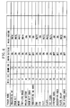
- Fig. 4 is a table showing the drive conditions for the volume controllers 57 corresponding, for example, to the situation in which a main character of a game is outside and the situation in which the main character is inside.
- each of the sound source reproducing channels 56 is assigned a particular part (musical instrument).
- the "Bank No.” is 0 for Channel 0 through Channel 4, Channel 14, and Channel 15, and is 1 for Channel 5 through Channel 13.
- the sound source reproducing channels 56 for each of the channels are driven based on the above-noted sequence data, and when the CPU 100 detects that the main character is at a location that is outside within a virtual space, the CPU 100 performs drive control so as to switch the volume controllers 57 corresponding to Channel 0 through Channel 9 and Channel 12 each to ON, and so as to switch the volume controllers 57 corresponding to Channel 10, Channel 11, and Channel 13 through Channel 15 to MUTE (OFF) , based on the volume control information.
- the background music formed with the sound source data reproduced by the sound source reproducing channels 56 corresponding to Channel 0 through Channel 9 and Channel 12 is output through the speaker units 11 of the television receiver 10.
- the background music is output at high volume.
- the CPU 100 detects that the main character is at a location that is inside within the virtual space, the CPU 100 performs drive control so as to switch the volume controllers 57 corresponding to Channel 4, Channel 6, Channel 10, Channel 11, and Channel 13 through Channel 15 each to ON, with the volume controllers 57 corresponding to the remaining channels switched to MUTE (OFF), based on the volume control information.
- volume control is performed in this manner, for example whereas in the case in which the main character is outside, not only are crowd noise and other noises output together with the background music output at predetermined volume, when the main character is moved inside, crowd and other noises almost cannot be heard, and the volume of the background music is lowered.
- FIG. 4 shows the case in which the volume controllers 57 corresponding to each channel are controlled in two-ways, that of ON and that of MUTE (OFF), it will be understood that it is further possible to perform step-wise adjustment of the volume level between more steps than merely ON and OFF.
- Another possibility is to set a sound generator to a predetermined object, such as a building or location (for example, a department store or congested town area), and to perform volume adjustment so as to gradually increase the sound volume as a character approaches a building or location and the like (or to apply MUTE to many channels at first and then gradually remove the MUTE condition and change to the ON condition).
- a sound generator to a predetermined object, such as a building or location (for example, a department store or congested town area), and to perform volume adjustment so as to gradually increase the sound volume as a character approaches a building or location and the like (or to apply MUTE to many channels at first and then gradually remove the MUTE condition and change to the ON condition).
- an entertainment system is provided with volume controllers 57 that adjust the output levels of sound source data reproduced in accordance with sequence data such as MIDI data, the CPU 100 of the entertainment system setting the gains (or setting the ON/OFF condition) of the volume controllers 57 responsive to particular scenes or situations, thereby enabling effective enactment of the various scenes and situations occurring in a video game.
Abstract
Description
Claims (9)
- A sound controller, comprising:means for sound source reproduction, which reproduces sound source information for each channel, in accordance with sequence information controlling a sound source reproducing operation for each channel; andmeans for adjusting an output level of the sound source information reproduced by the sound source reproduction means, minimally responsive to a scene or a situation.
- The sound controller according to claim 1, wherein
the output level adjusting means performs control of output and non-output of the sound source information reproduced by the sound source reproduction means, minimally responsive to a scene or a situation. - The sound controller according to claim 1 or 2, wherein
the sequence information comprises MIDI (Musical Instrument Digital Interface) information. - A method for controlling sound, comprising steps of:reproducing sound source information for each channel, in accordance with sequence information controlling a sound source reproducing operation for each channel; andadjusting an output level of the reproduced sound source information, minimally responsive to a scene or a situation.
- The method for controlling sound according to claim 4, further comprising a step of:controlling output and non-output of the reproduced sound source information, minimally responsive to a scene or a situation.
- The method for controlling sound according to claim 4 or 5, further comprising a step of:reproducing the sound source information of each channel, in accordance with MIDI information acting as the sequence information.
- Computer program product, comprising computer program means adapted to perform the method steps as defined in anyone of claims 4 to 6 when being executed on a computer, digital signal processor or the like.
- A computer readable storage medium having recorded thereon a computer program product according to claim 7.
- A program execution apparatus for executing a computer program product according to claim 7.
Applications Claiming Priority (4)
| Application Number | Priority Date | Filing Date | Title |
|---|---|---|---|
| JP2000398705 | 2000-12-27 | ||
| JP2000398705 | 2000-12-27 | ||
| JP2001349837A JP2002258842A (en) | 2000-12-27 | 2001-11-15 | Device, method, and program for sound control, computer- readable storage medium with stored sound control program, and program for executing device executing the sound control program |
| JP2001349837 | 2001-11-15 |
Publications (2)
| Publication Number | Publication Date |
|---|---|
| EP1225565A2 true EP1225565A2 (en) | 2002-07-24 |
| EP1225565A3 EP1225565A3 (en) | 2003-08-20 |
Family
ID=26606913
Family Applications (1)
| Application Number | Title | Priority Date | Filing Date |
|---|---|---|---|
| EP01130354A Withdrawn EP1225565A3 (en) | 2000-12-27 | 2001-12-19 | Sound controller that generates sound responsive to a situation |
Country Status (3)
| Country | Link |
|---|---|
| US (1) | US20020094866A1 (en) |
| EP (1) | EP1225565A3 (en) |
| JP (1) | JP2002258842A (en) |
Cited By (13)
| Publication number | Priority date | Publication date | Assignee | Title |
|---|---|---|---|---|
| WO2004025583A2 (en) * | 2002-09-10 | 2004-03-25 | Igt | Gaming device with enhanced sounds |
| CN100419675C (en) * | 2003-10-17 | 2008-09-17 | 株式会社巨摩 | Game software structure capable of audio playing |
| US7708642B2 (en) | 2001-10-15 | 2010-05-04 | Igt | Gaming device having pitch-shifted sound and music |
| US7789748B2 (en) | 2003-09-04 | 2010-09-07 | Igt | Gaming device having player-selectable music |
| US7892091B2 (en) | 2000-05-31 | 2011-02-22 | Igt | Gaming device and method for enhancing the issuance or transfer of an award |
| US7901291B2 (en) | 2001-09-28 | 2011-03-08 | Igt | Gaming device operable with platform independent code and method |
| US8016674B2 (en) | 2000-10-11 | 2011-09-13 | Igt | Gaming device having changed or generated player stimuli |
| US8491392B2 (en) | 2006-10-24 | 2013-07-23 | Igt | Gaming system and method having promotions based on player selected gaming environment preferences |
| US8591308B2 (en) | 2008-09-10 | 2013-11-26 | Igt | Gaming system and method providing indication of notable symbols including audible indication |
| US8740689B2 (en) | 2012-07-06 | 2014-06-03 | Igt | Gaming system and method configured to operate a game associated with a reflector symbol |
| CN104801043A (en) * | 2014-01-23 | 2015-07-29 | 腾讯科技(深圳)有限公司 | Method and device for scene sound effect control |
| WO2015147721A1 (en) * | 2014-03-26 | 2015-10-01 | Elias Software Ab | Sound engine for video games |
| US9245407B2 (en) | 2012-07-06 | 2016-01-26 | Igt | Gaming system and method that determines awards based on quantities of symbols included in one or more strings of related symbols displayed along one or more paylines |
Families Citing this family (34)
| Publication number | Priority date | Publication date | Assignee | Title |
|---|---|---|---|---|
| US7695363B2 (en) | 2000-06-23 | 2010-04-13 | Igt | Gaming device having multiple display interfaces |
| US7699699B2 (en) | 2000-06-23 | 2010-04-20 | Igt | Gaming device having multiple selectable display interfaces based on player's wagers |
| JP3597803B2 (en) * | 2001-07-16 | 2004-12-08 | 株式会社コナミコンピュータエンタテインメントスタジオ | Volume control program, volume control method, and video game apparatus |
| US7729915B2 (en) * | 2002-06-12 | 2010-06-01 | Enterprise Integration Group, Inc. | Method and system for using spatial metaphor to organize natural language in spoken user interfaces |
| JP2004147876A (en) * | 2002-10-30 | 2004-05-27 | Aruze Corp | Game machine |
| US7371175B2 (en) | 2003-01-13 | 2008-05-13 | At&T Corp. | Method and system for enhanced audio communications in an interactive environment |
| US7828657B2 (en) * | 2003-05-20 | 2010-11-09 | Turbine, Inc. | System and method for enhancing the experience of participant in a massively multiplayer game |
| JP3546209B1 (en) * | 2003-06-30 | 2004-07-21 | 株式会社コナミコンピュータエンタテインメント東京 | GAME DEVICE, COMPUTER CONTROL METHOD, AND PROGRAM |
| JP3732497B2 (en) * | 2004-01-14 | 2006-01-05 | コナミ株式会社 | Message output device, message control method, and program |
| US20070163427A1 (en) * | 2005-12-19 | 2007-07-19 | Alex Rigopulos | Systems and methods for generating video game content |
| US7459624B2 (en) | 2006-03-29 | 2008-12-02 | Harmonix Music Systems, Inc. | Game controller simulating a musical instrument |
| US20080139312A1 (en) * | 2006-12-08 | 2008-06-12 | Aruze Gaming America, Inc. | Gaming machine and volume control method thereof |
| JP5022700B2 (en) * | 2006-12-27 | 2012-09-12 | 株式会社東芝 | Ultrasonic diagnostic equipment |
| EP2173444A2 (en) | 2007-06-14 | 2010-04-14 | Harmonix Music Systems, Inc. | Systems and methods for simulating a rock band experience |
| US8678896B2 (en) | 2007-06-14 | 2014-03-25 | Harmonix Music Systems, Inc. | Systems and methods for asynchronous band interaction in a rhythm action game |
| US8558100B2 (en) | 2008-06-24 | 2013-10-15 | Sony Corporation | Music production apparatus and method of producing music by combining plural music elements |
| US8160064B2 (en) | 2008-10-22 | 2012-04-17 | Backchannelmedia Inc. | Systems and methods for providing a network link between broadcast content and content located on a computer network |
| US8465366B2 (en) | 2009-05-29 | 2013-06-18 | Harmonix Music Systems, Inc. | Biasing a musical performance input to a part |
| US8449360B2 (en) | 2009-05-29 | 2013-05-28 | Harmonix Music Systems, Inc. | Displaying song lyrics and vocal cues |
| US9364750B2 (en) | 2009-09-11 | 2016-06-14 | Steelseries Aps | Apparatus and method for enhancing a condition in a gaming application |
| EP2494432B1 (en) | 2009-10-27 | 2019-05-29 | Harmonix Music Systems, Inc. | Gesture-based user interface |
| US9981193B2 (en) | 2009-10-27 | 2018-05-29 | Harmonix Music Systems, Inc. | Movement based recognition and evaluation |
| US8874243B2 (en) | 2010-03-16 | 2014-10-28 | Harmonix Music Systems, Inc. | Simulating musical instruments |
| US8562403B2 (en) | 2010-06-11 | 2013-10-22 | Harmonix Music Systems, Inc. | Prompting a player of a dance game |
| US9358456B1 (en) | 2010-06-11 | 2016-06-07 | Harmonix Music Systems, Inc. | Dance competition game |
| CA2802348A1 (en) | 2010-06-11 | 2011-12-15 | Harmonix Music Systems, Inc. | Dance game and tutorial |
| US9024166B2 (en) | 2010-09-09 | 2015-05-05 | Harmonix Music Systems, Inc. | Preventing subtractive track separation |
| US9281793B2 (en) | 2012-05-29 | 2016-03-08 | uSOUNDit Partners, LLC | Systems, methods, and apparatus for generating an audio signal based on color values of an image |
| JP6266903B2 (en) * | 2013-06-19 | 2018-01-24 | 株式会社カプコン | Game sound volume level adjustment program and game system |
| CN104967913B (en) * | 2014-07-21 | 2019-01-08 | 腾讯科技(深圳)有限公司 | Audio file control method for playing back and device |
| CN108355356A (en) * | 2018-03-14 | 2018-08-03 | 网易(杭州)网络有限公司 | Scene of game sound intermediate frequency control method for playing back and device |
| IL259059A (en) * | 2018-04-30 | 2018-06-28 | Arcana Instr Ltd | A musical instrument with a joystick with variable tension and variable travel distance and a method of use thereof |
| CN109246474B (en) * | 2018-10-16 | 2021-03-02 | 维沃移动通信(杭州)有限公司 | Video file editing method and mobile terminal |
| WO2023026555A1 (en) * | 2021-08-25 | 2023-03-02 | ソニーグループ株式会社 | Information processing device, information processing method, and program |
Citations (4)
| Publication number | Priority date | Publication date | Assignee | Title |
|---|---|---|---|---|
| EP0301790A2 (en) * | 1987-07-24 | 1989-02-01 | BioControl Systems, Inc. | Biopotential digital controller for music and video applications |
| US5598478A (en) * | 1992-12-18 | 1997-01-28 | Victor Company Of Japan, Ltd. | Sound image localization control apparatus |
| US5689078A (en) * | 1995-06-30 | 1997-11-18 | Hologramaphone Research, Inc. | Music generating system and method utilizing control of music based upon displayed color |
| EP0969448A1 (en) * | 1998-06-30 | 2000-01-05 | Sony Corporation | Information processing apparatus and methods, and information providing media |
Family Cites Families (27)
| Publication number | Priority date | Publication date | Assignee | Title |
|---|---|---|---|---|
| US4314236A (en) * | 1977-01-12 | 1982-02-02 | Atari, Inc. | Apparatus for producing a plurality of audio sound effects |
| US4281833A (en) * | 1978-03-20 | 1981-08-04 | Sound Games, Inc. | Audio racquet ball |
| FI111789B (en) * | 1989-01-10 | 2003-09-15 | Nintendo Co Ltd | Electronic gaming apparatus with the possibility of pseudostereophonic development of sound |
| US5026051A (en) * | 1989-12-07 | 1991-06-25 | Qsound Ltd. | Sound imaging apparatus for a video game system |
| US5052685A (en) * | 1989-12-07 | 1991-10-01 | Qsound Ltd. | Sound processor for video game |
| JP3219860B2 (en) * | 1992-09-11 | 2001-10-15 | パイオニア株式会社 | Video game equipment |
| JP2552425B2 (en) * | 1993-12-14 | 1996-11-13 | コナミ株式会社 | Game console with live broadcast function |
| JP3528284B2 (en) * | 1994-11-18 | 2004-05-17 | ヤマハ株式会社 | 3D sound system |
| US5556107A (en) * | 1995-06-15 | 1996-09-17 | Apple Computer, Inc. | Computer game apparatus for providing independent audio in multiple player game systems |
| JP3153761B2 (en) * | 1996-03-06 | 2001-04-09 | 株式会社ナムコ | Game screen display method and game device |
| JPH1063470A (en) * | 1996-06-12 | 1998-03-06 | Nintendo Co Ltd | Souond generating device interlocking with image display |
| JP3870493B2 (en) * | 1996-08-02 | 2007-01-17 | 株式会社セガ | Competitive game equipment |
| JPH10137445A (en) * | 1996-11-07 | 1998-05-26 | Sega Enterp Ltd | Game device, visual sound processing device, and storage medium |
| JPH10211358A (en) * | 1997-01-28 | 1998-08-11 | Sega Enterp Ltd | Game apparatus |
| JP3890646B2 (en) * | 1997-01-30 | 2007-03-07 | 株式会社セガ | Sound generating apparatus and method in game machine |
| US6146276A (en) * | 1997-02-07 | 2000-11-14 | Okuniewicz; Douglas M. | Programmable electronic activity detector and command generator for electronic devices |
| US6464585B1 (en) * | 1997-11-20 | 2002-10-15 | Nintendo Co., Ltd. | Sound generating device and video game device using the same |
| JPH11219443A (en) * | 1998-01-30 | 1999-08-10 | Konami Co Ltd | Method and device for controlling display of character image, and recording medium |
| JPH11300039A (en) * | 1998-04-24 | 1999-11-02 | Namco Ltd | Game device and information storage medium |
| US6309301B1 (en) * | 1998-08-10 | 2001-10-30 | Namco Ltd. | Game communication with synchronization of soundtrack system |
| JP2982147B1 (en) * | 1998-10-08 | 1999-11-22 | コナミ株式会社 | Background sound switching device, background sound switching method, readable recording medium on which background sound switching program is recorded, and video game device |
| JP2000112485A (en) * | 1998-10-08 | 2000-04-21 | Konami Co Ltd | Background tone controller, background tone control method, readable recording medium recording background tone program, and video game device |
| JP2000210471A (en) * | 1999-01-21 | 2000-08-02 | Namco Ltd | Sound device and information recording medium for game machine |
| US6280329B1 (en) * | 1999-05-26 | 2001-08-28 | Nintendo Co., Ltd. | Video game apparatus outputting image and music and storage medium used therefor |
| JP2001009152A (en) * | 1999-06-30 | 2001-01-16 | Konami Co Ltd | Game system and storage medium readable by computer |
| WO2001015789A2 (en) * | 1999-08-31 | 2001-03-08 | Sony Computer Entertainment Inc. | Entertainment system, entertainment apparatus, recording medium, and program |
| JP2001190834A (en) * | 2000-01-06 | 2001-07-17 | Konami Co Ltd | Game system and computer readable recording medium for storing game program |
-
2001
- 2001-11-15 JP JP2001349837A patent/JP2002258842A/en active Pending
- 2001-12-19 EP EP01130354A patent/EP1225565A3/en not_active Withdrawn
- 2001-12-20 US US10/028,744 patent/US20020094866A1/en not_active Abandoned
Patent Citations (4)
| Publication number | Priority date | Publication date | Assignee | Title |
|---|---|---|---|---|
| EP0301790A2 (en) * | 1987-07-24 | 1989-02-01 | BioControl Systems, Inc. | Biopotential digital controller for music and video applications |
| US5598478A (en) * | 1992-12-18 | 1997-01-28 | Victor Company Of Japan, Ltd. | Sound image localization control apparatus |
| US5689078A (en) * | 1995-06-30 | 1997-11-18 | Hologramaphone Research, Inc. | Music generating system and method utilizing control of music based upon displayed color |
| EP0969448A1 (en) * | 1998-06-30 | 2000-01-05 | Sony Corporation | Information processing apparatus and methods, and information providing media |
Cited By (21)
| Publication number | Priority date | Publication date | Assignee | Title |
|---|---|---|---|---|
| US7892091B2 (en) | 2000-05-31 | 2011-02-22 | Igt | Gaming device and method for enhancing the issuance or transfer of an award |
| US8016674B2 (en) | 2000-10-11 | 2011-09-13 | Igt | Gaming device having changed or generated player stimuli |
| US8408996B2 (en) | 2000-10-11 | 2013-04-02 | Igt | Gaming device having changed or generated player stimuli |
| US7901291B2 (en) | 2001-09-28 | 2011-03-08 | Igt | Gaming device operable with platform independent code and method |
| US7666098B2 (en) | 2001-10-15 | 2010-02-23 | Igt | Gaming device having modified reel spin sounds to highlight and enhance positive player outcomes |
| US7708642B2 (en) | 2001-10-15 | 2010-05-04 | Igt | Gaming device having pitch-shifted sound and music |
| WO2004025583A2 (en) * | 2002-09-10 | 2004-03-25 | Igt | Gaming device with enhanced sounds |
| WO2004025583A3 (en) * | 2002-09-10 | 2004-07-29 | Igt Reno Nev | Gaming device with enhanced sounds |
| US7789748B2 (en) | 2003-09-04 | 2010-09-07 | Igt | Gaming device having player-selectable music |
| CN100419675C (en) * | 2003-10-17 | 2008-09-17 | 株式会社巨摩 | Game software structure capable of audio playing |
| US8491392B2 (en) | 2006-10-24 | 2013-07-23 | Igt | Gaming system and method having promotions based on player selected gaming environment preferences |
| US9017173B2 (en) | 2006-10-24 | 2015-04-28 | Igt | Gaming system and method having promotions based on player selected gaming environment preferences |
| US8591308B2 (en) | 2008-09-10 | 2013-11-26 | Igt | Gaming system and method providing indication of notable symbols including audible indication |
| US9135785B2 (en) | 2008-09-10 | 2015-09-15 | Igt | Gaming system and method providing indication of notable symbols |
| US9530287B2 (en) | 2008-09-10 | 2016-12-27 | Igt | Gaming system and method providing indication of notable symbols |
| US8740689B2 (en) | 2012-07-06 | 2014-06-03 | Igt | Gaming system and method configured to operate a game associated with a reflector symbol |
| US9245407B2 (en) | 2012-07-06 | 2016-01-26 | Igt | Gaming system and method that determines awards based on quantities of symbols included in one or more strings of related symbols displayed along one or more paylines |
| CN104801043A (en) * | 2014-01-23 | 2015-07-29 | 腾讯科技(深圳)有限公司 | Method and device for scene sound effect control |
| CN104801043B (en) * | 2014-01-23 | 2019-12-13 | 腾讯科技(深圳)有限公司 | Method and device for controlling scene sound effect |
| WO2015147721A1 (en) * | 2014-03-26 | 2015-10-01 | Elias Software Ab | Sound engine for video games |
| US10688393B2 (en) | 2014-03-26 | 2020-06-23 | Elias Software Ab | Sound engine for video games |
Also Published As
| Publication number | Publication date |
|---|---|
| EP1225565A3 (en) | 2003-08-20 |
| JP2002258842A (en) | 2002-09-11 |
| US20020094866A1 (en) | 2002-07-18 |
Similar Documents
| Publication | Publication Date | Title |
|---|---|---|
| EP1225565A2 (en) | Sound controller that generates sound responsive to a situation | |
| US6699123B2 (en) | Entertainment system, entertainment apparatus, recording medium, and program | |
| US6409601B2 (en) | Entertainment system and supply medium | |
| US6402616B1 (en) | Entertainment system, supply medium, and manual control input device | |
| US7096079B2 (en) | Audio processing and image generating apparatus, audio processing and image generating method, recording medium and program | |
| JP2002222436A (en) | Object control method, object control processing program executed by computer, computer readable-recording medium with recorded object control processing program executed by computer, and program executing device executing object control processing program | |
| US6960137B2 (en) | Sound control method and device for expressing game presence | |
| US20120196681A1 (en) | Game system and game program medium | |
| US7145569B2 (en) | Data processing method | |
| US7136080B1 (en) | Entertainment system, entertainment apparatus, recording medium, and program providing color coded display messages | |
| JP2004187706A (en) | Game music performing program, game device, and game music performing method | |
| US20010048762A1 (en) | Image processing apparatus, image processing method, recording medium and program | |
| US6390919B1 (en) | Entertainment system, entertainment apparatus, recording medium, and program | |
| JP3472544B2 (en) | Entertainment system, entertainment apparatus, recording medium and method | |
| US7058462B1 (en) | Entertainment system, entertainment apparatus, recording medium, and program | |
| JP3499203B2 (en) | Audio processing / image generation apparatus, audio processing / image generation method, and recording medium | |
| JP3427049B2 (en) | Image processing apparatus, method, recording medium, and program | |
| EP1095680A2 (en) | Image processing apparatus, image processing method, recording medium and program | |
| EP1095681A2 (en) | Audio processing and image generating apparatus, audio processing and image generating method, recording medium and program | |
| JP2005081007A (en) | Game system, program, and information storage medium | |
| JP2001154656A (en) | Entertainment system, entertainment device, recording medium and program | |
| MXPA00003077A (en) | Entertainment system, supply medium, and manual control input device | |
| MXPA00002994A (en) | Entertainment system and supply medium |
Legal Events
| Date | Code | Title | Description |
|---|---|---|---|
| PUAI | Public reference made under article 153(3) epc to a published international application that has entered the european phase |
Free format text: ORIGINAL CODE: 0009012 |
|
| AK | Designated contracting states |
Kind code of ref document: A2 Designated state(s): AT BE CH CY DE DK ES FI FR GB GR IE IT LI LU MC NL PT SE TR |
|
| AX | Request for extension of the european patent |
Free format text: AL;LT;LV;MK;RO;SI |
|
| PUAL | Search report despatched |
Free format text: ORIGINAL CODE: 0009013 |
|
| AK | Designated contracting states |
Designated state(s): AT BE CH CY DE DK ES FI FR GB GR IE IT LI LU MC NL PT SE TR |
|
| AX | Request for extension of the european patent |
Extension state: AL LT LV MK RO SI |
|
| RIC1 | Information provided on ipc code assigned before grant |
Ipc: 7G 10H 1/00 B Ipc: 7G 10H 1/46 A |
|
| AKX | Designation fees paid | ||
| REG | Reference to a national code |
Ref country code: DE Ref legal event code: 8566 |
|
| STAA | Information on the status of an ep patent application or granted ep patent |
Free format text: STATUS: THE APPLICATION IS DEEMED TO BE WITHDRAWN |
|
| 18D | Application deemed to be withdrawn |
Effective date: 20040221 |