EP1226858A2 - Toothed rim for filter cartridge - Google Patents
Toothed rim for filter cartridge Download PDFInfo
- Publication number
- EP1226858A2 EP1226858A2 EP02354019A EP02354019A EP1226858A2 EP 1226858 A2 EP1226858 A2 EP 1226858A2 EP 02354019 A EP02354019 A EP 02354019A EP 02354019 A EP02354019 A EP 02354019A EP 1226858 A2 EP1226858 A2 EP 1226858A2
- Authority
- EP
- European Patent Office
- Prior art keywords
- crown
- dovetail
- slide
- cartridge
- teeth
- Prior art date
- Legal status (The legal status is an assumption and is not a legal conclusion. Google has not performed a legal analysis and makes no representation as to the accuracy of the status listed.)
- Granted
Links
- 210000003323 beak Anatomy 0.000 claims description 7
- 238000012423 maintenance Methods 0.000 claims description 2
- 230000002349 favourable effect Effects 0.000 description 1
- 238000001914 filtration Methods 0.000 description 1
- 238000004519 manufacturing process Methods 0.000 description 1
- 238000000034 method Methods 0.000 description 1
- 230000000717 retained effect Effects 0.000 description 1
- 239000012815 thermoplastic material Substances 0.000 description 1
Images

Classifications
-
- B—PERFORMING OPERATIONS; TRANSPORTING
- B01—PHYSICAL OR CHEMICAL PROCESSES OR APPARATUS IN GENERAL
- B01D—SEPARATION
- B01D29/00—Filters with filtering elements stationary during filtration, e.g. pressure or suction filters, not covered by groups B01D24/00 - B01D27/00; Filtering elements therefor
- B01D29/11—Filters with filtering elements stationary during filtration, e.g. pressure or suction filters, not covered by groups B01D24/00 - B01D27/00; Filtering elements therefor with bag, cage, hose, tube, sleeve or like filtering elements
- B01D29/13—Supported filter elements
- B01D29/15—Supported filter elements arranged for inward flow filtration
- B01D29/21—Supported filter elements arranged for inward flow filtration with corrugated, folded or wound sheets
-
- B—PERFORMING OPERATIONS; TRANSPORTING
- B01—PHYSICAL OR CHEMICAL PROCESSES OR APPARATUS IN GENERAL
- B01D—SEPARATION
- B01D2201/00—Details relating to filtering apparatus
- B01D2201/12—Pleated filters
- B01D2201/127—Pleated filters with means for keeping the spacing between the pleats
-
- B—PERFORMING OPERATIONS; TRANSPORTING
- B01—PHYSICAL OR CHEMICAL PROCESSES OR APPARATUS IN GENERAL
- B01D—SEPARATION
- B01D2201/00—Details relating to filtering apparatus
- B01D2201/40—Special measures for connecting different parts of the filter
- B01D2201/4084—Snap or Seeger ring connecting means
Definitions
- the invention relates to a holding device which fits onto a cartridge.
- cylindrical filter in which the filter element consists of a large number of plies to obtain maximum filtration area in reduced volume.
- the pleat holding device consists of a circular crown molded in a suitable thermoplastic material and with teeth facing inwards, each tooth fitting between two folds.
- the number of crowns to be placed can be variable.
- crowns closed on themselves lies in their setting in place which can only be done by threading them through the ends of the folds when these are not yet positioned and maintained. This operation is long and delicate, therefore expensive.
- the subject of the present invention is a crown eliminating these drawbacks, in the form of an open part capable of taking the circular shape sought by hooking or stapling the two ends one over the other.
- the invention relates to a ring gear ensuring positioning and holding the filter element of a pleated cartridge, the crown comprising a belt fitted with a series of teeth equal in number to the number of folds the cartridge, the teeth being directed inwards so as to be inserted between consecutive folds of the cartridge.
- the crown is formed by a belt open which can take a circular shape during assembly, and both ends delimiting the opening of the belt, are stapled to each other of so as to ensure the continuity of the teeth and a good dimension of use of the crown.
- the crowns When assembling the cartridge, the crowns can be fixed on a tool which keeps them in a favorable position, in particular rectilinear. In this position, the introduction of the folds of the filter media is clearly facilitated, and we can even consider an automatic distribution of these folds, if the importance of the series to be produced justifies it. Otherwise, the introduction can remain manual, but becomes significantly easier, therefore faster and less expensive.
- the stapling is obtained by means of a accessory part comprising a slide engaged on one of the ends of the crown, and snapping onto the other end.
- one of the ends comprises a first part in dovetail, a ramp with a first beak hooking, and a terminal tab on which the slide is supported during engagement on the dovetail.
- the other end has a second part in dovetail shape similar to the first part in dovetail, and the slide includes oblique faces in the form of dovetail, and a central groove ending in a second beak attachment intended to cooperate with the first attachment nozzle.
- the slide given its shape and size, can easily be molded at the same time as the crown, which gives it a cost of almost zero manufacturing.
- the right end has a dovetail portion 16 similar to 11, bounded on the right by facets 17, 17 '.
- Figure 3 shows the slide 21 in the position that it will be presented, the slot 22 coming over the belt, to the right of part 16.
- the slider must then be moved to the left by engaging on the part dovetail 16, which implies that it itself carries a groove in dovetail, not visible in this figure.
Abstract
Description
L'invention est relative à un dispositif de maintien s'adaptant sur une cartouche de filtre cylindrique dans laquelle l'élément filtrant est constitué d'un grand nombre de plis permettant d'obtenir un maximum de surface de filtration dans un volume réduit.The invention relates to a holding device which fits onto a cartridge. cylindrical filter in which the filter element consists of a large number of plies to obtain maximum filtration area in reduced volume.
Pour obtenir une bonne efficacité des plis, il est important que ceux-ci soient correctement rangés et maintenus à un écartement précis sur toute leur hauteur.To obtain a good efficiency of the folds, it is important that they are correctly stored and kept at a precise spacing over their entire height.
Selon une technique connue, le dispositif de maintien des plis est constitué par une couronne circulaire moulée dans un matériau thermoplastique adéquat et portant des dents dirigées vers l'intérieur, chaque dent s'insérant entre deux plis. Selon la hauteur de la cartouche, le nombre de couronnes à placer peut être variable.According to a known technique, the pleat holding device consists of a circular crown molded in a suitable thermoplastic material and with teeth facing inwards, each tooth fitting between two folds. Depending on the height of the cartridge, the number of crowns to be placed can be variable.
L'inconvénient des couronnes fermées sur elles - mêmes réside dans leur mise en place qui ne peut se faire qu'en les enfilant par l'extrémité des plis lorsque ceux-ci ne sont pas encore positionnés et maintenus. Cette opération est longue et délicate, donc coûteuse.The disadvantage of crowns closed on themselves lies in their setting in place which can only be done by threading them through the ends of the folds when these are not yet positioned and maintained. This operation is long and delicate, therefore expensive.
Pour la même raison, il est impossible de remplacer une couronne sur une cartouche existante, ou d'en ajouter une ou plusieurs si des conditions sévères d'exploitation nécessitent un maintien plus robuste.For the same reason, it is impossible to replace a crown on a existing cartridge, or add one or more if severe conditions operating conditions require more robust maintenance.
La présente invention a pour objet une couronne éliminant ces inconvénients, en se présentant sous la forme d'une pièce ouverte susceptible de prendre la forme circulaire recherchée par accrochage ou agrafage des deux extrémités l'une sur l'autre.The subject of the present invention is a crown eliminating these drawbacks, in the form of an open part capable of taking the circular shape sought by hooking or stapling the two ends one over the other.
L'invention concerne une couronne dentée assurant le positionnement et le maintien de l'élément filtrant d'une cartouche plissée, la couronne comportant une ceinture équipée d'une série de dents en nombre égal au nombre de plis de la cartouche, les dents étant dirigées vers l'intérieur de manière à s'insérer entre les plis consécutifs de la cartouche. La couronne est formée par une ceinture ouverte susceptible de prendre une forme circulaire lors du montage, et les deux extrémités délimitant l'ouverture de la ceinture, sont agrafées l'une à l'autre de manière à assurer la continuité des dents et une bonne dimension d'utilisation de la couronne. The invention relates to a ring gear ensuring positioning and holding the filter element of a pleated cartridge, the crown comprising a belt fitted with a series of teeth equal in number to the number of folds the cartridge, the teeth being directed inwards so as to be inserted between consecutive folds of the cartridge. The crown is formed by a belt open which can take a circular shape during assembly, and both ends delimiting the opening of the belt, are stapled to each other of so as to ensure the continuity of the teeth and a good dimension of use of the crown.
Lors de l'assemblage de la cartouche, les couronnes peuvent être fixées sur un outillage qui les maintient dans une position favorable, notamment rectiligne. Dans cette position, l'introduction des plis du média-filtrant est nettement facilitée, et on peut même envisager une distribution automatique de ces plis, si l'importance des séries à fabriquer le justifie. Dans le cas contraire, l'introduction peut rester manuelle, mais devient nettement plus aisée, donc plus rapide et moins coûteuse.When assembling the cartridge, the crowns can be fixed on a tool which keeps them in a favorable position, in particular rectilinear. In this position, the introduction of the folds of the filter media is clearly facilitated, and we can even consider an automatic distribution of these folds, if the importance of the series to be produced justifies it. Otherwise, the introduction can remain manual, but becomes significantly easier, therefore faster and less expensive.
Selon une caractéristique de l'invention, l'agrafage est obtenu au moyen d'une pièce accessoire comprenant un coulisseau engagé sur une des extrémités de la couronne, et venant s'encliqueter sur l'autre extrémité.According to a characteristic of the invention, the stapling is obtained by means of a accessory part comprising a slide engaged on one of the ends of the crown, and snapping onto the other end.
Selon une mode de réalisation préférentiel, l'une des extrémités comprend une première partie en queue d'aronde, une rampe dotée d'un premier bec d'accrochage, et une languette terminale sur laquelle le coulisseau prend appui lors de l'engagement sur la queue d'aronde. L'autre extrémité comporte une deuxième partie en queue d'aronde de forme similaire à la première partie en queue d'aronde, et le coulisseau comprend des faces obliques en forme de queue d'aronde, et une rainure centrale se terminant par un deuxième bec d'accrochage destiné à coopérer avec le premier bec d'accrochage.According to a preferred embodiment, one of the ends comprises a first part in dovetail, a ramp with a first beak hooking, and a terminal tab on which the slide is supported during engagement on the dovetail. The other end has a second part in dovetail shape similar to the first part in dovetail, and the slide includes oblique faces in the form of dovetail, and a central groove ending in a second beak attachment intended to cooperate with the first attachment nozzle.
Bien entendu, l'introduction d'une couronne sur une cartouche déjà assemblée ne pose aucun problème, notamment si l'agrafage est correctement conçu. Pour réaliser cet agrafage, on peut envisager, sans sortir du cadre de l'invention, diverses catégories de solutions :
- agrafage direct des deux extrémités de la pièce l'une sur l'autre.
- utilisation d'une pièce d'agrafage séparée.
- direct stapling of the two ends of the part one on the other.
- use of a separate stapling piece.
D'autres avantages et caractéristiques ressortiront plus clairement de la description qui va suivre d'un mode de mise en oeuvre de l'invention donnée à titre d'exemple, et représenté aux dessins annexés, dans lesquels:
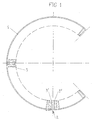
- la figure 1 est une vue en plan d'une couronne de l'invention.
- la figure 2 est une vue en perspective agrandie des deux extrémités de la couronne placées en regard l'une de l'autre, préalablement à l'agrafage.
- la figure 3 est la vue en perspective correspondante d'une pièce d'agrafage séparée désignée ci-après coulisseau, vue selon sa face externe.
- la figure 4 est une vue en perspective dudit coulisseau, vue selon la face interne.
- Figure 1 is a plan view of a crown of the invention.
- Figure 2 is an enlarged perspective view of the two ends of the crown placed opposite one another, prior to stapling.
- Figure 3 is the corresponding perspective view of a separate stapling part designated hereinafter slide, seen along its external face.
- Figure 4 is a perspective view of said slide, seen along the internal face.
On peut noter que le coulisseau, vu sa forme et sa dimension, peut facilement être moulé en même temps que la couronne, ce qui lui donne un coût de fabrication quasi-nul.It can be noted that the slide, given its shape and size, can easily be molded at the same time as the crown, which gives it a cost of almost zero manufacturing.
La figure 1 montre les deux éléments constitutifs de la couronne :
- la
ceinture 1 qui, au lieu de former un anneau fermé, présente une ouverture en 2. - les
dents 3, dont le nombre égal au nombre de plis de la cartouche.
- the
belt 1 which, instead of forming a closed ring, has an opening in 2. -
teeth 3, the number of which is equal to the number of folds in the cartridge.
Il est avantageux de mouler la pièce dans la forme représentée, pour travailler avec un moule de forme générale carrée, et aussi pour que la forme naturelle de la pièce soit proche de celle qu'elle aura une fois montée. Toutefois, compte tenu de sa grande souplesse, on pourrait envisager de la mouler sous toute autre forme, y compris rectiligne.It is advantageous to mold the part in the form shown, to work with a mold of generally square shape, and also so that the natural shape of the part is close to that which it will have once assembled. However, account given its great flexibility, we could consider mold it under any other shape, including straight.
Sur la figure 1, les dents d'extrémité 3', 3"sont plus écartées que le pas normal,
afin de retrouver ce pas quand les extrémités auront été rapprochées et
agrafées.In FIG. 1, the
La figure 2 montre la configuration des deux extrémités à assembler. Celle de gauche comporte les éléments suivants :
- une partie en queue d'aronde 11
- une
rampe 12 se terminant vers la gauche par un bec d'accrochage 13 - une
collerette 14 permettant une préhension facile entre deux doigts lors de la manoeuvre d'agrafage - une languette d'extrémité 15 sur laquelle le coulisseau viendra prendre appui pour faciliter son engagement sur la queue d'aronde, dont les extrémités sont chanfreinées dans le même but. 11, 12, et 13 sont des éléments fonctionnels, alors que 14 et 15 sont plutôt des éléments ergonomiques.
- a
dovetail part 11 - a
ramp 12 ending to the left by a hookingspout 13 - a
flange 14 allowing easy gripping between two fingers during the stapling operation - an
end tab 15 on which the slide will come to bear to facilitate its engagement on the dovetail, the ends of which are chamfered for the same purpose. 11, 12, and 13 are functional elements, while 14 and 15 are rather ergonomic elements.
L'extrémité de droite comporte une partie en queue d'aronde 16 similaire à 11,
limitée à droite par les facettes 17, 17'.The right end has a
La figure 3 montre le coulisseau 21 dans la position selon laquelle il sera
présenté, le créneau 22 venant coiffer la ceinture, à droite de la partie 16. Le
coulisseau doit ensuite être déplacé vers la gauche en s'engageant sur la partie
en queue d'aronde 16, ce qui implique qu'il porte lui-même une rainure en
queue d'aronde, non visible sur cette figure.Figure 3 shows the
La figure 4 montre précisément la face opposée du coulisseau 21, et notamment :
- les faces obliques 23 ,23' de la rainure en queue d'aronde
- la
rainure 24, se terminant vers la gauche par un bec d'accrochage 25 appelé à coopérer avec lebec 13 présenté sur la figure 2.
- the
oblique faces 23, 23 'of the dovetail groove - the
groove 24, ending to the left by a hooking spout 25 called to cooperate with thespout 13 presented in FIG. 2.
Pour l'agrafage, le coulisseau ayant été préalablement engagé sur la partie 16
de l'extrémité droite de la couronne, il suffit d'appuyer l'une contre l'autre les
deux extrémités et de pousser le coulisseau vers la gauche. Son élasticité lui
permet de monter sur la rampe 12 présentée sur la figure 2, jusqu'à ce que son
bec d'accrochage 25 vienne tomber derrière le bec 13. L'agrafage est alors
réalisé, les facettes 17, 17' de la couronne étant retenues par les facettes 26,
26' du coulisseau.For stapling, the slide having been previously engaged on
En position agrafée, il y a continuité de forme entre le coulisseau 21 et la
collerette 14, afin de donner à l'ensemble une esthétique satisfaisante.In the stapled position, there is continuity of shape between the
Claims (3)
caractérisée en ce que :
characterized in that :
Applications Claiming Priority (2)
| Application Number | Priority Date | Filing Date | Title |
|---|---|---|---|
| FR0101246 | 2001-01-30 | ||
| FR0101246A FR2820051B1 (en) | 2001-01-30 | 2001-01-30 | TOOTHED CROWN FOR FILTER CARTRIDGE |
Publications (3)
| Publication Number | Publication Date |
|---|---|
| EP1226858A2 true EP1226858A2 (en) | 2002-07-31 |
| EP1226858A3 EP1226858A3 (en) | 2002-10-30 |
| EP1226858B1 EP1226858B1 (en) | 2004-09-22 |
Family
ID=8859408
Family Applications (1)
| Application Number | Title | Priority Date | Filing Date |
|---|---|---|---|
| EP02354019A Expired - Lifetime EP1226858B1 (en) | 2001-01-30 | 2002-01-29 | Toothed rim for filter cartridge |
Country Status (4)
| Country | Link |
|---|---|
| EP (1) | EP1226858B1 (en) |
| AT (1) | ATE276817T1 (en) |
| DE (1) | DE60201275D1 (en) |
| FR (1) | FR2820051B1 (en) |
Cited By (1)
| Publication number | Priority date | Publication date | Assignee | Title |
|---|---|---|---|---|
| WO2006124876A2 (en) * | 2005-05-16 | 2006-11-23 | Pall Corporation | Pleated fluid treatment arrangements and methods for stabilizing the pleats |
Citations (4)
| Publication number | Priority date | Publication date | Assignee | Title |
|---|---|---|---|---|
| US2988227A (en) * | 1958-03-03 | 1961-06-13 | Harold H Harms | Pleated filter |
| US3305161A (en) * | 1964-09-29 | 1967-02-21 | Walker Mfg Co | Tubular filter shell |
| US5169524A (en) * | 1990-11-27 | 1992-12-08 | Horst Meiritz | Filter ring |
| US5601717A (en) * | 1994-11-09 | 1997-02-11 | Siebec S.A. | Filter media cartridge |
Family Cites Families (4)
| Publication number | Priority date | Publication date | Assignee | Title |
|---|---|---|---|---|
| US3319796A (en) * | 1964-09-02 | 1967-05-16 | Rosaen Filter Co | Filter element |
| US5807483A (en) * | 1995-12-15 | 1998-09-15 | Kuss Corporation | Snap latch filter ring for a fuel injector |
| US5820754A (en) * | 1995-12-15 | 1998-10-13 | Kuss Corporation | Snap latch filter ring for a fuel injector |
| ES2345252T3 (en) * | 1998-10-09 | 2010-09-20 | Entegris, Inc. | FILTRATION MODULE. |
-
2001
- 2001-01-30 FR FR0101246A patent/FR2820051B1/en not_active Expired - Fee Related
-
2002
- 2002-01-29 EP EP02354019A patent/EP1226858B1/en not_active Expired - Lifetime
- 2002-01-29 DE DE60201275T patent/DE60201275D1/en not_active Expired - Lifetime
- 2002-01-29 AT AT02354019T patent/ATE276817T1/en not_active IP Right Cessation
Patent Citations (4)
| Publication number | Priority date | Publication date | Assignee | Title |
|---|---|---|---|---|
| US2988227A (en) * | 1958-03-03 | 1961-06-13 | Harold H Harms | Pleated filter |
| US3305161A (en) * | 1964-09-29 | 1967-02-21 | Walker Mfg Co | Tubular filter shell |
| US5169524A (en) * | 1990-11-27 | 1992-12-08 | Horst Meiritz | Filter ring |
| US5601717A (en) * | 1994-11-09 | 1997-02-11 | Siebec S.A. | Filter media cartridge |
Cited By (2)
| Publication number | Priority date | Publication date | Assignee | Title |
|---|---|---|---|---|
| WO2006124876A2 (en) * | 2005-05-16 | 2006-11-23 | Pall Corporation | Pleated fluid treatment arrangements and methods for stabilizing the pleats |
| WO2006124876A3 (en) * | 2005-05-16 | 2007-03-01 | Pall Corp | Pleated fluid treatment arrangements and methods for stabilizing the pleats |
Also Published As
| Publication number | Publication date |
|---|---|
| ATE276817T1 (en) | 2004-10-15 |
| EP1226858B1 (en) | 2004-09-22 |
| FR2820051B1 (en) | 2003-12-12 |
| DE60201275D1 (en) | 2004-10-28 |
| FR2820051A1 (en) | 2002-08-02 |
| EP1226858A3 (en) | 2002-10-30 |
Similar Documents
| Publication | Publication Date | Title |
|---|---|---|
| EP0669088A1 (en) | Hair clip with elastic rings | |
| EP1213980A1 (en) | Device for locking in position a mobile part relative to a fixed part | |
| EP0150046A2 (en) | Bracelet for watch | |
| EP0911565A2 (en) | Quick-acting connection between a rigid pipe and a connector | |
| FR2859510A1 (en) | ASSEMBLY STRUCTURE | |
| EP0847710B1 (en) | Spring hinge for hair article | |
| EP0293948A1 (en) | Key head and key with such a head | |
| EP0904572A1 (en) | Method for fixing a watchband to a watch case | |
| FR2685614A1 (en) | LINK STRAP, ESPECIALLY FOR A WATCH. | |
| EP1796917B1 (en) | Writing instrument | |
| WO1999025236A1 (en) | Device for connecting a vacuum cleaner dust bag | |
| EP1226858B1 (en) | Toothed rim for filter cartridge | |
| CA2004034C (en) | Binding for album of samples | |
| EP2836155A1 (en) | Device for adhering orthodontic attachments and method for manufacturing said device | |
| EP1717459B1 (en) | Device for fixing a member to a panel comprising an assembly made out of a cage and an insert and method for manufacturing said assembly | |
| EP3009311A1 (en) | Securing device between a wiper blade and a support constituting a windscreen wiper | |
| EP1714689B1 (en) | Filter element, filtration system with such a filter element and method for manufacturing such a filtration system | |
| WO2002103626A1 (en) | Microcircuit card with detachable wafer | |
| EP0962175A1 (en) | Fastening device for curtain rod | |
| EP3801371B1 (en) | Device for storing orthodontic pliers | |
| FR2568650A1 (en) | Device for clamping a flexible element such as a cord, string, lace or the like | |
| EP3248848B1 (en) | Securing device for fitting a windscreen wiper on a drive arm, and corresponding wiping system | |
| EP0209496A1 (en) | Button cover with spring means | |
| EP0528700A1 (en) | Adjustable clamp for lighter support | |
| FR2868914A1 (en) | Instrument for making incisions in bread dough portions has body that partially covers cutting blade and leaves part of cutting edge exposed |
Legal Events
| Date | Code | Title | Description |
|---|---|---|---|
| PUAI | Public reference made under article 153(3) epc to a published international application that has entered the european phase |
Free format text: ORIGINAL CODE: 0009012 |
|
| AK | Designated contracting states |
Kind code of ref document: A2 Designated state(s): AT BE CH CY DE DK ES FI FR GB GR IE IT LI LU MC NL PT SE TR |
|
| AX | Request for extension of the european patent |
Free format text: AL;LT;LV;MK;RO;SI |
|
| PUAL | Search report despatched |
Free format text: ORIGINAL CODE: 0009013 |
|
| AK | Designated contracting states |
Kind code of ref document: A3 Designated state(s): AT BE CH CY DE DK ES FI FR GB GR IE IT LI LU MC NL PT SE TR |
|
| AX | Request for extension of the european patent |
Free format text: AL;LT;LV;MK;RO;SI |
|
| RIC1 | Information provided on ipc code assigned before grant |
Free format text: 7B 01D 29/21 A |
|
| 17P | Request for examination filed |
Effective date: 20030429 |
|
| AKX | Designation fees paid |
Designated state(s): AT BE CH CY DE DK ES FI FR GB GR IE IT LI LU MC NL PT SE TR |
|
| 17Q | First examination report despatched |
Effective date: 20030916 |
|
| GRAP | Despatch of communication of intention to grant a patent |
Free format text: ORIGINAL CODE: EPIDOSNIGR1 |
|
| GRAS | Grant fee paid |
Free format text: ORIGINAL CODE: EPIDOSNIGR3 |
|
| GRAA | (expected) grant |
Free format text: ORIGINAL CODE: 0009210 |
|
| AK | Designated contracting states |
Kind code of ref document: B1 Designated state(s): AT BE CH CY DE DK ES FI FR GB GR IE IT LI LU MC NL PT SE TR |
|
| PG25 | Lapsed in a contracting state [announced via postgrant information from national office to epo] |
Ref country code: IT Free format text: LAPSE BECAUSE OF FAILURE TO SUBMIT A TRANSLATION OF THE DESCRIPTION OR TO PAY THE FEE WITHIN THE PRESCRIBED TIME-LIMIT;WARNING: LAPSES OF ITALIAN PATENTS WITH EFFECTIVE DATE BEFORE 2007 MAY HAVE OCCURRED AT ANY TIME BEFORE 2007. THE CORRECT EFFECTIVE DATE MAY BE DIFFERENT FROM THE ONE RECORDED. Effective date: 20040922 Ref country code: IE Free format text: LAPSE BECAUSE OF FAILURE TO SUBMIT A TRANSLATION OF THE DESCRIPTION OR TO PAY THE FEE WITHIN THE PRESCRIBED TIME-LIMIT Effective date: 20040922 Ref country code: TR Free format text: LAPSE BECAUSE OF FAILURE TO SUBMIT A TRANSLATION OF THE DESCRIPTION OR TO PAY THE FEE WITHIN THE PRESCRIBED TIME-LIMIT Effective date: 20040922 Ref country code: NL Free format text: LAPSE BECAUSE OF FAILURE TO SUBMIT A TRANSLATION OF THE DESCRIPTION OR TO PAY THE FEE WITHIN THE PRESCRIBED TIME-LIMIT Effective date: 20040922 Ref country code: AT Free format text: LAPSE BECAUSE OF FAILURE TO SUBMIT A TRANSLATION OF THE DESCRIPTION OR TO PAY THE FEE WITHIN THE PRESCRIBED TIME-LIMIT Effective date: 20040922 Ref country code: FI Free format text: LAPSE BECAUSE OF FAILURE TO SUBMIT A TRANSLATION OF THE DESCRIPTION OR TO PAY THE FEE WITHIN THE PRESCRIBED TIME-LIMIT Effective date: 20040922 Ref country code: GB Free format text: LAPSE BECAUSE OF FAILURE TO SUBMIT A TRANSLATION OF THE DESCRIPTION OR TO PAY THE FEE WITHIN THE PRESCRIBED TIME-LIMIT Effective date: 20040922 |
|
| REG | Reference to a national code |
Ref country code: GB Ref legal event code: FG4D Free format text: NOT ENGLISH |
|
| REG | Reference to a national code |
Ref country code: CH Ref legal event code: EP |
|
| REG | Reference to a national code |
Ref country code: IE Ref legal event code: FG4D Free format text: FRENCH |
|
| REF | Corresponds to: |
Ref document number: 60201275 Country of ref document: DE Date of ref document: 20041028 Kind code of ref document: P |
|
| PG25 | Lapsed in a contracting state [announced via postgrant information from national office to epo] |
Ref country code: SE Free format text: LAPSE BECAUSE OF FAILURE TO SUBMIT A TRANSLATION OF THE DESCRIPTION OR TO PAY THE FEE WITHIN THE PRESCRIBED TIME-LIMIT Effective date: 20041222 Ref country code: GR Free format text: LAPSE BECAUSE OF FAILURE TO SUBMIT A TRANSLATION OF THE DESCRIPTION OR TO PAY THE FEE WITHIN THE PRESCRIBED TIME-LIMIT Effective date: 20041222 Ref country code: DK Free format text: LAPSE BECAUSE OF FAILURE TO SUBMIT A TRANSLATION OF THE DESCRIPTION OR TO PAY THE FEE WITHIN THE PRESCRIBED TIME-LIMIT Effective date: 20041222 |
|
| PG25 | Lapsed in a contracting state [announced via postgrant information from national office to epo] |
Ref country code: DE Free format text: LAPSE BECAUSE OF FAILURE TO SUBMIT A TRANSLATION OF THE DESCRIPTION OR TO PAY THE FEE WITHIN THE PRESCRIBED TIME-LIMIT Effective date: 20041223 |
|
| PG25 | Lapsed in a contracting state [announced via postgrant information from national office to epo] |
Ref country code: ES Free format text: LAPSE BECAUSE OF FAILURE TO SUBMIT A TRANSLATION OF THE DESCRIPTION OR TO PAY THE FEE WITHIN THE PRESCRIBED TIME-LIMIT Effective date: 20050102 |
|
| PG25 | Lapsed in a contracting state [announced via postgrant information from national office to epo] |
Ref country code: CY Free format text: LAPSE BECAUSE OF FAILURE TO SUBMIT A TRANSLATION OF THE DESCRIPTION OR TO PAY THE FEE WITHIN THE PRESCRIBED TIME-LIMIT Effective date: 20050129 Ref country code: LU Free format text: LAPSE BECAUSE OF NON-PAYMENT OF DUE FEES Effective date: 20050129 |
|
| PG25 | Lapsed in a contracting state [announced via postgrant information from national office to epo] |
Ref country code: MC Free format text: LAPSE BECAUSE OF NON-PAYMENT OF DUE FEES Effective date: 20050131 Ref country code: BE Free format text: LAPSE BECAUSE OF NON-PAYMENT OF DUE FEES Effective date: 20050131 |
|
| NLV1 | Nl: lapsed or annulled due to failure to fulfill the requirements of art. 29p and 29m of the patents act | ||
| GBV | Gb: ep patent (uk) treated as always having been void in accordance with gb section 77(7)/1977 [no translation filed] |
Effective date: 20040922 |
|
| REG | Reference to a national code |
Ref country code: IE Ref legal event code: FD4D |
|
| PLBE | No opposition filed within time limit |
Free format text: ORIGINAL CODE: 0009261 |
|
| STAA | Information on the status of an ep patent application or granted ep patent |
Free format text: STATUS: NO OPPOSITION FILED WITHIN TIME LIMIT |
|
| BERE | Be: lapsed |
Owner name: SOC. SIEBEC Effective date: 20050131 |
|
| 26N | No opposition filed |
Effective date: 20050623 |
|
| PG25 | Lapsed in a contracting state [announced via postgrant information from national office to epo] |
Ref country code: LI Free format text: LAPSE BECAUSE OF NON-PAYMENT OF DUE FEES Effective date: 20060131 Ref country code: CH Free format text: LAPSE BECAUSE OF NON-PAYMENT OF DUE FEES Effective date: 20060131 |
|
| REG | Reference to a national code |
Ref country code: CH Ref legal event code: PL |
|
| BERE | Be: lapsed |
Owner name: SOC. *SIEBEC Effective date: 20050131 |
|
| PG25 | Lapsed in a contracting state [announced via postgrant information from national office to epo] |
Ref country code: PT Free format text: LAPSE BECAUSE OF NON-PAYMENT OF DUE FEES Effective date: 20050222 |
|
| REG | Reference to a national code |
Ref country code: FR Ref legal event code: TP |
|
| REG | Reference to a national code |
Ref country code: FR Ref legal event code: PLFP Year of fee payment: 15 |
|
| REG | Reference to a national code |
Ref country code: FR Ref legal event code: PLFP Year of fee payment: 16 |
|
| REG | Reference to a national code |
Ref country code: FR Ref legal event code: PLFP Year of fee payment: 17 |
|
| PGFP | Annual fee paid to national office [announced via postgrant information from national office to epo] |
Ref country code: FR Payment date: 20210127 Year of fee payment: 20 |