EP1233191A2 - Hydraulic oscillator as a machine drive - Google Patents
Hydraulic oscillator as a machine drive Download PDFInfo
- Publication number
- EP1233191A2 EP1233191A2 EP01128622A EP01128622A EP1233191A2 EP 1233191 A2 EP1233191 A2 EP 1233191A2 EP 01128622 A EP01128622 A EP 01128622A EP 01128622 A EP01128622 A EP 01128622A EP 1233191 A2 EP1233191 A2 EP 1233191A2
- Authority
- EP
- European Patent Office
- Prior art keywords
- hydraulic
- machine
- pump
- motor
- pressure
- Prior art date
- Legal status (The legal status is an assumption and is not a legal conclusion. Google has not performed a legal analysis and makes no representation as to the accuracy of the status listed.)
- Granted
Links
Images


Classifications
-
- F—MECHANICAL ENGINEERING; LIGHTING; HEATING; WEAPONS; BLASTING
- F15—FLUID-PRESSURE ACTUATORS; HYDRAULICS OR PNEUMATICS IN GENERAL
- F15B—SYSTEMS ACTING BY MEANS OF FLUIDS IN GENERAL; FLUID-PRESSURE ACTUATORS, e.g. SERVOMOTORS; DETAILS OF FLUID-PRESSURE SYSTEMS, NOT OTHERWISE PROVIDED FOR
- F15B7/00—Systems in which the movement produced is definitely related to the output of a volumetric pump; Telemotors
- F15B7/005—With rotary or crank input
- F15B7/006—Rotary pump input
-
- B—PERFORMING OPERATIONS; TRANSPORTING
- B30—PRESSES
- B30B—PRESSES IN GENERAL
- B30B1/00—Presses, using a press ram, characterised by the features of the drive therefor, pressure being transmitted directly, or through simple thrust or tension members only, to the press ram or platen
- B30B1/10—Presses, using a press ram, characterised by the features of the drive therefor, pressure being transmitted directly, or through simple thrust or tension members only, to the press ram or platen by toggle mechanism
- B30B1/16—Presses, using a press ram, characterised by the features of the drive therefor, pressure being transmitted directly, or through simple thrust or tension members only, to the press ram or platen by toggle mechanism operated by fluid-pressure means
-
- F—MECHANICAL ENGINEERING; LIGHTING; HEATING; WEAPONS; BLASTING
- F15—FLUID-PRESSURE ACTUATORS; HYDRAULICS OR PNEUMATICS IN GENERAL
- F15B—SYSTEMS ACTING BY MEANS OF FLUIDS IN GENERAL; FLUID-PRESSURE ACTUATORS, e.g. SERVOMOTORS; DETAILS OF FLUID-PRESSURE SYSTEMS, NOT OTHERWISE PROVIDED FOR
- F15B1/00—Installations or systems with accumulators; Supply reservoir or sump assemblies
- F15B1/02—Installations or systems with accumulators
- F15B1/024—Installations or systems with accumulators used as a supplementary power source, e.g. to store energy in idle periods to balance pump load
-
- F—MECHANICAL ENGINEERING; LIGHTING; HEATING; WEAPONS; BLASTING
- F15—FLUID-PRESSURE ACTUATORS; HYDRAULICS OR PNEUMATICS IN GENERAL
- F15B—SYSTEMS ACTING BY MEANS OF FLUIDS IN GENERAL; FLUID-PRESSURE ACTUATORS, e.g. SERVOMOTORS; DETAILS OF FLUID-PRESSURE SYSTEMS, NOT OTHERWISE PROVIDED FOR
- F15B21/00—Common features of fluid actuator systems; Fluid-pressure actuator systems or details thereof, not covered by any other group of this subclass
- F15B21/12—Fluid oscillators or pulse generators
-
- F—MECHANICAL ENGINEERING; LIGHTING; HEATING; WEAPONS; BLASTING
- F15—FLUID-PRESSURE ACTUATORS; HYDRAULICS OR PNEUMATICS IN GENERAL
- F15B—SYSTEMS ACTING BY MEANS OF FLUIDS IN GENERAL; FLUID-PRESSURE ACTUATORS, e.g. SERVOMOTORS; DETAILS OF FLUID-PRESSURE SYSTEMS, NOT OTHERWISE PROVIDED FOR
- F15B21/00—Common features of fluid actuator systems; Fluid-pressure actuator systems or details thereof, not covered by any other group of this subclass
- F15B21/14—Energy-recuperation means
-
- B—PERFORMING OPERATIONS; TRANSPORTING
- B29—WORKING OF PLASTICS; WORKING OF SUBSTANCES IN A PLASTIC STATE IN GENERAL
- B29C—SHAPING OR JOINING OF PLASTICS; SHAPING OF MATERIAL IN A PLASTIC STATE, NOT OTHERWISE PROVIDED FOR; AFTER-TREATMENT OF THE SHAPED PRODUCTS, e.g. REPAIRING
- B29C45/00—Injection moulding, i.e. forcing the required volume of moulding material through a nozzle into a closed mould; Apparatus therefor
- B29C45/17—Component parts, details or accessories; Auxiliary operations
- B29C45/76—Measuring, controlling or regulating
- B29C45/7666—Measuring, controlling or regulating of power or energy, e.g. integral function of force
- B29C2045/7673—Recovering energy or power from drive motors
-
- B—PERFORMING OPERATIONS; TRANSPORTING
- B29—WORKING OF PLASTICS; WORKING OF SUBSTANCES IN A PLASTIC STATE IN GENERAL
- B29C—SHAPING OR JOINING OF PLASTICS; SHAPING OF MATERIAL IN A PLASTIC STATE, NOT OTHERWISE PROVIDED FOR; AFTER-TREATMENT OF THE SHAPED PRODUCTS, e.g. REPAIRING
- B29C45/00—Injection moulding, i.e. forcing the required volume of moulding material through a nozzle into a closed mould; Apparatus therefor
- B29C45/17—Component parts, details or accessories; Auxiliary operations
- B29C45/46—Means for plasticising or homogenising the moulding material or forcing it into the mould
- B29C45/47—Means for plasticising or homogenising the moulding material or forcing it into the mould using screws
- B29C45/50—Axially movable screw
- B29C45/5008—Drive means therefor
-
- B—PERFORMING OPERATIONS; TRANSPORTING
- B29—WORKING OF PLASTICS; WORKING OF SUBSTANCES IN A PLASTIC STATE IN GENERAL
- B29C—SHAPING OR JOINING OF PLASTICS; SHAPING OF MATERIAL IN A PLASTIC STATE, NOT OTHERWISE PROVIDED FOR; AFTER-TREATMENT OF THE SHAPED PRODUCTS, e.g. REPAIRING
- B29C45/00—Injection moulding, i.e. forcing the required volume of moulding material through a nozzle into a closed mould; Apparatus therefor
- B29C45/17—Component parts, details or accessories; Auxiliary operations
- B29C45/64—Mould opening, closing or clamping devices
- B29C45/68—Mould opening, closing or clamping devices hydro-mechanical
- B29C45/681—Mould opening, closing or clamping devices hydro-mechanical using a toggle mechanism as mould clamping device
-
- B—PERFORMING OPERATIONS; TRANSPORTING
- B29—WORKING OF PLASTICS; WORKING OF SUBSTANCES IN A PLASTIC STATE IN GENERAL
- B29C—SHAPING OR JOINING OF PLASTICS; SHAPING OF MATERIAL IN A PLASTIC STATE, NOT OTHERWISE PROVIDED FOR; AFTER-TREATMENT OF THE SHAPED PRODUCTS, e.g. REPAIRING
- B29C45/00—Injection moulding, i.e. forcing the required volume of moulding material through a nozzle into a closed mould; Apparatus therefor
- B29C45/17—Component parts, details or accessories; Auxiliary operations
- B29C45/76—Measuring, controlling or regulating
- B29C45/7666—Measuring, controlling or regulating of power or energy, e.g. integral function of force
-
- Y—GENERAL TAGGING OF NEW TECHNOLOGICAL DEVELOPMENTS; GENERAL TAGGING OF CROSS-SECTIONAL TECHNOLOGIES SPANNING OVER SEVERAL SECTIONS OF THE IPC; TECHNICAL SUBJECTS COVERED BY FORMER USPC CROSS-REFERENCE ART COLLECTIONS [XRACs] AND DIGESTS
- Y02—TECHNOLOGIES OR APPLICATIONS FOR MITIGATION OR ADAPTATION AGAINST CLIMATE CHANGE
- Y02P—CLIMATE CHANGE MITIGATION TECHNOLOGIES IN THE PRODUCTION OR PROCESSING OF GOODS
- Y02P70/00—Climate change mitigation technologies in the production process for final industrial or consumer products
- Y02P70/10—Greenhouse gas [GHG] capture, material saving, heat recovery or other energy efficient measures, e.g. motor control, characterised by manufacturing processes, e.g. for rolling metal or metal working
Abstract
Description
Die Erfindung betrifft eine Vorrichtung zum kontrollierten Antrieb einer Maschinenachse, bestehend aus einem hydraulischen Aktuator, einer hydraulischen Pumpe, die hydraulisch mit dem Aktuator verbunden ist, und einem drehzahlvariablen Elektromotor, der die hydraulische Pumpe antreibt.The invention relates to a device for controlled Drive of a machine axis, consisting of a hydraulic one Actuator, a hydraulic pump that is hydraulic is connected to the actuator, and a speed variable Electric motor that drives the hydraulic pump.
Viele Arbeitsmaschinen wie sie z.B. zum Stanzen, Nibbeln, Prägen, Hämmern, Umformen, Spritzgiessen oder Druckgiessen benutzt werden, zeichnen sich durch schnelle zyklische Bewegungen aus. Bei einer Stanzmaschine bestimmt die Kraft des Werkzeugantriebes weitgehend die maximale Grösse der Werkzeuge oder die maximale Dicke des bearbeitbaren Materials. Die Geschwindigkeit des Antriebes wiederum beeinflusst die Hubzahl pro Minute, eine wichtige Kenngrösse hinsichtlich Produktivität.Many work machines such as for punching, nibbling, Embossing, hammering, forming, injection molding or die casting are used, are characterized by fast cyclical movements out. With a punching machine, the force of the Tool drive largely the maximum size of the tools or the maximum thickness of the machinable material. The speed of the drive in turn influences the Number of strokes per minute, an important parameter in terms of Productivity.
Wegen den hohen Anforderungen an Kraft und Geschwindigkeit werden die Werkzeugantriebe solcher Maschinen oft hydraulisch ausgeführt. In Verbindung mit schnellen Ventilen und einer elektronischen Steuerung lassen sich so wichtige Prozessparameter wie etwa das Geschwindigkeitsprofil den Erfordernissen des Arbeitsprozesses flexibel anpassen.Because of the high demands on power and speed the tool drives of such machines are often hydraulic executed. In connection with fast valves and an electronic control can be so important Process parameters such as the speed profile Adapt the requirements of the work process flexibly.
Im Bereich geregelter hydraulischer Antriebe hat sich die Ventiltechnik durchgesetzt. Eine typische Lösung der obigen Aufgabe besteht darin, den Arbeitszylinder mit einem Regelventil oder Servoventil auszurüsten. Die Geschwindigkeit des Zylinders kann so genau gesteuert werden. Dem Zylinder lässt sich ein gewünschtes Geschwindigkeitsprofil aufprägen. Neben klassischen Regel- oder Servoventilen gibt es auch eine ganze Reihe von Spezialventilen, die für diese Art von Maschinen entwickelt wurden.In the area of controlled hydraulic drives, the Valve technology prevailed. A typical solution to the above Task is the working cylinder with a control valve or equip servo valve. The speed of the Cylinder can be controlled so precisely. The cylinder leaves memorize a desired speed profile. Next classic control or servo valves are also available whole series of special valves that are used for this type of Machines were developed.
Die Lösung mit Ventilen hat den Nachteil, daß an den Steuerkanten der Ventile erhebliche Drosselverluste entstehen. Diese erwärmen das Hydraulikmedium und führen über die Zeit zu grossen Energie- oder Betriebskosten der Maschine. Aus diesem Grund wurden in letzter Zeit neue Lösungen diskutiert. Eine vorteilhafte Lösung besteht in einem Direktantrieb durch eine drehzahlgeregelte Hydraulikpumpe (WO-A-97/05387). Der Zylinder wird dabei direkt mit der Pumpe verbunden. Der Ölstrom wird durch die Pumpe oder durch den Antriebsmotor der Pumpe und nicht mehr durch das Ventil gesteuert. Damit wird das Ventil als hydraulisches Stellglied überflüssig. Die Aufgabe der Leistungssteuerung wird nun von leistungselektronischen Stellgliedern insbesondere Leistungstransistoren übernommen. Diese Komponenten befinden sich in der Regel im Umrichter, der den drehzahlvariablen Elektromotor mit Strom versorgt. Die Hydraulik übernimmt dabei nur noch die Aufgabe eines hydrostatischen Getriebes, die Steuerung und Regelung der Leistung wird durch die Elektrotechnik, insbesondere den Umrichter und den Elektromotor wahrgenommen.The solution with valves has the disadvantage that at the control edges the valves cause considerable throttling losses. These heat the hydraulic medium and lead over time at high energy or operating costs of the machine. Out for this reason, new solutions have been discussed recently. An advantageous solution is a direct drive by a speed-controlled hydraulic pump (WO-A-97/05387). The cylinder is directly connected to the pump connected. The oil flow is through the pump or through the Drive motor of the pump and no longer through the valve controlled. This turns the valve into a hydraulic actuator superfluous. The task of power control is now of power electronic actuators in particular Power transistors taken over. These components are located usually in the converter, which is the speed variable Electric motor powered. The hydraulics take over only the task of a hydrostatic transmission, the control and regulation of the performance is through the Electrical engineering, in particular the converter and the electric motor perceived.
Die Substitution von hydraulischen Stellgliedern wie Regelpumpen oder Ventilen durch elektronische Stellglieder, hat vielfältige Vorteile. Neben den Energieeinsparungen lässt sich durch dieses Vorgehen eine deutlich bessere Regelqualität, so unter anderem eine höhere Reproduzierbarkeit und eine höhere Temperaturstabilität bei deutlich tieferer Lärmentwicklung realisieren.The substitution of hydraulic actuators such as control pumps or valves by electronic actuators diverse advantages. In addition to the energy savings this procedure results in a significantly better control quality, among other things a higher reproducibility and higher temperature stability with significantly lower Realize noise development.
Auf der anderen Seite hat diese Lösung aber auch den Nachteil, daß der Elektromotor in der Regel eine grosse Trägheit aufweist, welche bei zyklischen Bewegungen hoher Frequenz entsprechend oft beschleunigt und verzögert werden muss. Dies schränkt die erreichbare Hubzahl solcher Antriebe stark ein und führt dazu, daß ein wesentlicher Teil der Motorenleistung für die Überwindung der Rotationsträgheit des Motors verwendet wird. Nur ein Teil der Motorenleistung steht so dem eigentlichen Arbeitsprozess zur Verfügung.On the other hand, this solution also has the disadvantage that the electric motor is usually very inert which, in the case of cyclical movements of high frequency must be accelerated and decelerated accordingly often. This severely limits the achievable number of strokes of such drives and leads to a substantial part of engine performance for overcoming the rotational inertia of the Motors is used. Only part of the engine power is thus available to the actual work process.
Je höher die Frequenz der Bewegung, desto mehr ist der Motor mit seiner eigenen Trägheit beschäftigt. Im Extremfall folgt der Motor während des ganzen Zyklus mit vollem Moment dem vorgegebenen Geschwindigkeitsprofil, ohne gegen aussen Arbeit zu verrichten. Dieser Zustand wird bei der maximal erreichbaren Hubzahl des Antriebes erreicht. Gegen aussen wird dann keine Energie mehr abgegeben, die Wicklungen des Motors sind ständig mit dem Maximalstrom beaufschlagt und erwärmen diesen entsprechend.The higher the frequency of the movement, the more the motor is concerned with its own laziness. In extreme cases follows the engine at full torque throughout the cycle given speed profile without facing outside To do work. This condition is at the maximum achievable stroke rate of the drive. Towards the outside then no more energy is released, the windings of the Motors are constantly subjected to the maximum current and heat it up accordingly.
Die Erfindung setzt sich zum Ziel, schnelle zyklische Antriebe für hydraulische Maschinen zu schaffen, die ohne Regelventile arbeiten, mit leistungselektronischen Stellgliedern gesteuert werden und einem zyklischen Geschwindigkeitsprofil bei deutlich tieferem Leistungsbedarf folgen. Der geringere antriebseigene Leistungsbedarf soll es ermöglichen, höhere Hubzahlen bei tieferem Energieverbrauch zu realisieren oder einen höheren Leistungsanteil für den Arbeitsprozess in der Maschine verfügbar zu machen.The invention sets itself the goal of fast cyclic drives to create for hydraulic machines without Control valves work with power electronic actuators be controlled and a cyclical speed profile follow with significantly lower power requirements. The lower drive power requirement should enable higher stroke rates with lower energy consumption realize or a higher performance share for the Make the work process available in the machine.
Es ist ein weiteres Ziel der Erfindung, einen solchen Antrieb als Antriebsmodul zu gestalten, das für eine Vielzahl von Maschinen und Antriebsaufgaben eingesetzt werden kann. Die Erfindung soll also ganz allgemein als Antrieb einer Maschinenachse auslegbar sein.It is another object of the invention to provide such a drive to be designed as a drive module for a multitude of machines and drive tasks can be used. The invention is therefore intended to drive a Machine axis can be designed.
Erfindungsgemäss wirken zwei hydraulische Zylinder auf die anzutreibende Maschinenachse. Auf diese Weise entstehen vier Kammern, die hydraulisch mit der Maschinenachse verknüpft sind. Eine Kammer pro Zylinder ist mit je einem der beiden Anschlüsse einer hydraulischen Pumpe verbunden. Die jeweils andere Kammer der beiden Zylinder ist mit je einem Energiespeicher verbunden. Die Pumpe ist gekoppelt mit einem Elektromotor und wird von diesem angetrieben.According to the invention, two hydraulic cylinders act on the machine axis to be driven. This creates four Chambers that are hydraulically linked to the machine axis are. One chamber per cylinder is with one of the two Connections of a hydraulic pump connected. The each the other chamber of the two cylinders each has an energy store connected. The pump is coupled to a Electric motor and is driven by it.
Die Hydraulikpumpe wirkt im geschlossenen hydraulischen Kreis auf die beiden angeschlossenen Zylinderkammern. Wird die Pumpe in eine Richtung vom Elektromotor angetrieben fährt die Maschinenachse in eine Richtung. Eine Richtungsumkehr des Elektromotors hat entsprechend eine Richtungsumkehr der Maschinenachse zur Folge.The hydraulic pump works in the closed hydraulic Circle on the two connected cylinder chambers. Becomes the pump is driven in one direction by the electric motor the machine axis moves in one direction. A change of direction of the electric motor accordingly has a reversal of direction the machine axis.
Die beiden Energiespeicher beaufschlagen die Maschinenachse mit einer rücktreibenden Potentialkraft, welche im allgemeinen mit zunehmendem Verfahrweg des einen Zylinders zunimmt und im gegenüberliegenden Zylinder entsprechend abnimmt. Sind die Energiespeicher als Druckspeicher ausgebildet sind die Potentialkräfte Druckkräfte auf die Kolben der Zylinder. Die Energiespeicher können z.B. auch als elastische Feder ausgebildet sein.The two energy stores act on the machine axis with a driving potential force, which in general increases with increasing travel of one cylinder and decreases accordingly in the opposite cylinder. Are the energy stores designed as pressure stores the potential forces compressive forces on the pistons of the cylinders. The energy stores can e.g. also as an elastic spring be trained.
Die beiden Energiespeicher wirken wie zwei Federn auf beiden Seiten der Lastmasse und machen aus dem System einen Oszillator. Die Geschwindigkeit von Hydraulikpumpe und Elektromotor sind hydraulisch mit der Lastmasse gekoppelt. Entsprechend ist die Lastmasse zusammen mit dem Rotationsträgheitsmoment von Pumpe und Motor wie eine einzige Massenträgheit zwischen zwei Federn zu betrachten. Dies gilt zumindest in erster Näherung, wenn man das eingespannte Öl als nicht kompressibel betrachtet.The two energy stores act like two springs on both Sides of the load mass and make the system an oscillator. The speed of the hydraulic pump and electric motor are hydraulically coupled to the load mass. Corresponding is the load mass together with the rotational moment of inertia of pump and motor like a single inertia between two feathers. this applies at least in the first approximation, if you look at the clamped oil considered as not compressible.
Wird dieses System in ausgelenktem Zustand dem freien Spiel der Kräfte überlassen, ergibt sich eine Eigenschwingung des Feder-Masse-Systems, die im Wesentlichen durch die beiden Energiespeicher sowie alle Massen und Rotationsträgheiten definiert ist. Diese Eigenschwingung wird durch die hydraulischen und mechanischen Verlustleistung aller Komponenten gedämpft. In einem solchen erfindungsgemässen Oszillator wird Energie zwischen den Energiespeichern und der Maschinenachse bei einer Bewegung ausgetauscht. Druckenergie im Druckspeicher beschleunigt die Maschinenachse und wird damit in kinetische Energie von Maschine, Pumpe und Elektromotor umgewandelt. Bei einer Verzögerung wird wiederum kinetische Energie in potentielle Energie gewandelt.This system is in the deflected state of free play left to the forces, there is a natural vibration of the Spring mass system, essentially by the two Energy storage as well as all masses and rotational inertia is defined. This natural vibration is caused by the hydraulic and mechanical power loss of all components attenuated. In such an oscillator according to the invention becomes energy between the energy stores and the machine axis exchanged during a movement. Pressure energy in Accumulator accelerates the machine axis and becomes in kinetic energy from the machine, pump and electric motor converted. In the case of a delay, it becomes kinetic Energy turned into potential energy.
Die Kräfte des Motors sind über die Leistungselektronik genau und sehr dynamisch steuerbar. Mit der Vorrichtung kann so auch eine Position gehalten oder ein beliebiges Geschwindigkeitsprofil gefahren werden. Im Allgemeinen wirken die Potentialkräfte der Energiespeicher als zusätzliche Lasten auf den Motor, die je nach dem die Bewegung der Vorrichtung unterstützen oder belasten können. Bei einer oszillierenden Bewegung wirken die Kräfte der Energiespeicher bei geeigneter Auslegung unterstützend, d.h. führen zu einer Reduktion des mittleren Strombelags des Motors verglichen zum gleichen Bewegungszyklus ohne Potentialkräfte der Energiespeicher.The forces of the motor are via the power electronics precisely and very dynamically controllable. With the device can so also held a position or any speed profile be driven. Generally they work Potential forces of energy storage as additional loads on the motor depending on the the movement of the device can support or burden. With an oscillating The forces of energy storage act in a suitable manner when moving Supporting interpretation, i.e. lead to a reduction of the average current of the motor compared to the same Movement cycle without potential energy storage.
Stimmt der Bewegungszyklus der Maschine mit der Eigenschwingung der Vorrichtung überein, muss der Motor nur noch minimale Verlustleistungen und die von der Vorrichtung gegen aussen verrichtete Leistung aufbringen. Im Idealfall werden also 100% der Antriebsleistung dem Arbeitsprozess als Nutzleistung zugeführt, wenn von Reibungen und hydraulischen Verlusten einmal abgesehen wird. Dies ganz im Gegensatz zu einem System nach dem Stand der Technik, das im schlechtesten Fall (bei der maximal erreichbaren Frequenz) die ganze Motorenleistung zur Beschleunigung des Motors benötigt und 0% der Antriebsleistung gegen aussen abgeben kann. Dies gilt auch bei einer Vernachlässigung von hydraulischen Verlusten in den Leitungen oder von Reibungsverlusten in den Komponenten der Vorrichtung.Is the movement cycle of the machine correct with the natural vibration? the device, the motor only has to be minimal Power dissipation and that of the device against Provide outside performance. Ideally be So 100% of the drive power to the work process as useful work fed when from friction and hydraulic Losses are disregarded. This is in complete contrast to a state of the art system that is at its worst Case (at the maximum attainable frequency) the whole Engine power needed to accelerate the engine and 0% of the drive power can be given to the outside. this applies even if hydraulic losses are neglected in the lines or of friction losses in the components the device.
Die Erfindung schlägt also einen neuen Antrieb mit elektrischer Leistungssteuerung für Maschinen vor, die zyklisch Bewegungen mit hohen Beschleunigungen fahren müssen. Ein Elektromotor treibt eine Pumpe, welche wiederum direkt mit einem Zylinder verbunden ist. Dieser Anordnung wird ein System von Druckspeichern und Ventilen aufgeschaltet, die dem System die Eigenschaft eines Oszillators geben. Die Beschleunigungskräfte bei einer zyklischen Bewegung nahe an der Resonanz werden dann weitgehend von den Druckspeichern und den damit verbundenen Zylindern geleistet.The invention therefore proposes a new drive with electrical Power control for machines that are cyclical Must move at high accelerations. On The electric motor drives a pump, which in turn is also included is connected to a cylinder. This arrangement becomes a System of pressure accumulators and valves switched on give the system the property of an oscillator. The Accelerating forces during a cyclical movement close to the response will then largely be from the accumulators and the associated cylinders.
Dies führt zu einer Entlastung des Elektromotors und ermöglicht geringere Leistungen auf der Maschine zu installieren oder aber bei gleicher Leistung kürzere Zykluszeiten der Maschine zu realisieren.This leads to a relief of the electric motor and enables to install less power on the machine or shorter cycle times with the same output the machine.
Verschiedene Ausführungsbeispiele der Erfindung sind in den Zeichnungen dargestellt und werden im folgenden anhand der Zeichnungen näher beschrieben. Es zeigt
- Fig. 1
- eine schematische Darstellung einer erfindungsgemäßen Vorrichtung zum Antrieb einer Lastmasse;
- Fig. 2
- eine schematische Darstellung einer erfindungsgemäßen Vorrichtung zum Antrieb einer Stanz- oder Prägmaschine;
- Fig. 3
- eine schematische Darstellung einer erfindungsgemäßen Vorrichtung zum Antrieb einer Einspritzeinheit einer Spritzgiessmaschine;
- Fig. 4
- eine schematische Darstellung einer erfindungsgemäßen Vorrichtung zum Antrieb eines Kniehebelmechanismus; und
- Fig. 5
- eine schematische Darstellung einer erfindungsgemäßen Vorrichtung zum Antrieb eines Drehgelenks.
- Fig. 1
- is a schematic representation of an inventive device for driving a load mass;
- Fig. 2
- a schematic representation of a device according to the invention for driving a punching or embossing machine;
- Fig. 3
- a schematic representation of a device according to the invention for driving an injection unit of an injection molding machine;
- Fig. 4
- a schematic representation of a device according to the invention for driving a toggle lever mechanism; and
- Fig. 5
- is a schematic representation of a device according to the invention for driving a rotary joint.
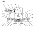
In Figur 1 wird ein erfindungsgemässer Antrieb dazu eingesetzt,
eine Maschinenachse anzutreiben, bestehend aus einer
Lastmasse 20, die auf den Führungen 18, 19 in Richtung X
verschiebbar ist. Die Pumpe 3 ist hydraulisch mit zwei
Kammern 16, 17 der Zylinder 10, 11 verbunden. Die beiden
Zylinderstangen 21, 22 der Zylinder 10, 11 sind über die
Last 20 mechanisch gekoppelt. Die Anordnung wirkt so wie ein
einziger Zylinder, der im geschlossenen Kreis von der Pumpe
3 mit Drucköl versorgt wird.In FIG. 1, a drive according to the invention is used to
to drive a machine axis consisting of one
Die Lager 12,13 symbolisieren eine feste mechanische Verbindung
mit der Maschine. Die Leckageleitung 4 der Pumpe 3
führt einen kleinen Ölstrom in den Tank 7 ab. Über die
beiden Rückschlagventile 5,6 gelangt das Öl wieder zurück in
den Antriebskreislauf sobald der Druck in einer der beiden
Pumpenanschlüsse unter das Druckniveau im Tank 7 sinkt. Der
Tank 7 kann dabei als Tank, separate Pumpengruppe oder
andere Druckquelle ausgebildet sein.The
Fährt die Anordnung in Richtung X, so wird das Öl in der
Kammer 14 in den Druckspeicher 8 ausgestossen und erhöht
damit den Druck im Druckspeicher 8. Entsprechend vergrössert
sich das Volumen in der Kammer 15 und sinkt der Druck im
Druckspeicher 9. Daraus resultiert eine rücktreibende Kraft,
welche durch die Drücke in den beiden Kammern 14, 15 definiert
ist und sich mit zunehmender Auslenkung in Richtung X
erhöht.If the arrangement moves in direction X, the oil in the
Erfindungsgemäss werden die Komponenten nun so ausgelegt,
daß die rücktreibenden Kräfte das gewünschte Geschwindigkeitsprofil
des Antriebes ideal unterstützen. Werden die
Vorspanndrücke in den Druckspeichern 8, 9 sehr klein gewählt
oder vernachlässigt, so ergibt sich praktisch ein reiner
Pumpenantrieb im geschlossenen Kreis. Mit zunehmendem Druck
in den Druckspeichern werden die Federkräfte der Druckspeicher
grösser und unterstützen bei entsprechender Auslegung
die gewünschte, zyklische Bewegung der Lastmasse. Motor 2,
Pumpe 3, Zylinderstangen 21, 22 und Lastmasse 20 müssen dann
nicht mehr ausschliesslich von den elektro-magnetischen
Kräften des Motors 2 beschleunigt werden, sondern werden
dabei von den Druckkräften der Druckspeicher unterstützt.According to the invention, the components are now designed so
that the restoring forces have the desired speed profile
ideally support the drive. Will the
Preload pressures in the
Je näher die Soll-Bewegung der Eigenschwingung des Systems kommt, desto höher der Leistungsanteil der Druckspeicherkräfte und desto geringer der Leistungsanteil des Motors.The closer the target movement to the natural vibration of the system comes, the higher the performance share of the pressure storage forces and the lower the power share of the engine.
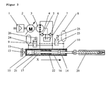
Figur 2 zeigt eine besonders vorteilhafte Ausgestaltung
einer erfindungsgemässen Vorrichtung zum Antrieb einer
Stanz- oder Prägmaschine. Die beiden Zylinder 10,11 wurden
in einem Block 22 vereint. Als zusätzliches Element wurden
zwei Ventile 24,25 eingebracht. Die Zylinderkammern 14,15
können mittels den Ventilmagneten 23,26 von den Druckspeichern
8,9 auf den Tank 7 geschaltet werden.Figure 2 shows a particularly advantageous embodiment
an inventive device for driving a
Punching or embossing machine. The two cylinders were 10.11
united in a
Damit wird auch die Federkraft von den Zylindern weggeschaltet. Schaltet man bei einer zyklischen Bewegung der Achse nach der Bewegungsumkehr die Druckspeicher aus, so ergibt sich in der Folge eine Phase im Bewegungszyklus, die nur noch vom Elektromotor getrieben ist. Dieser Betrieb kann sinnvoll sein, wenn relativ grosse Hübe bei näherungsweise konstanter Geschwindigkeit gefahren werden sollen.This also switches the spring force away from the cylinders. One switches when the axis moves cyclically after the reversal of movement the pressure accumulator, so results subsequently a phase in the movement cycle that only is still driven by the electric motor. This operation can be useful if relatively large strokes at approx should be driven at a constant speed.
Das Zu- und Abschalten der Ventile 24,25 kann durch die
Position der Kolbenstange gesteuert werden, die Ventile
24,25 können auch im Zylinder integriert sein. Das Zu- und
Abschalten geschieht dann immer an der gleichen Stelle. Der
Antrieb verhält sich so wie ein Trampolinspringer, der auf
eine Feder springt und von dieser zurückgeworfen wird um in
der Folge eine näherungsweise kräftefreie, ballistische
Bewegung zu machen. Erfindungsgemäss werden die Kräfte des
Elektromotors 2 nur dazu verwendet, die Eigenform der Bewegung
zu beeinflussen, damit die resultierende Bewegung den
Erfordernissen des Arbeitsprozesses entspricht.The
Die Druckspeicher 8,9,27,28 können auch für weitere hydraulische
Nebenfunktionen verwendet werden wie etwa kleine
Hilfskolben oder Ventilvorsteuerungen. Es braucht sich nicht
notwendigerweise um 4 unabhängige Druckspeicher zu handeln,
die Funktion des Oszillators kann auch mit nur einem Druckspeicher
gewährleistet werden.The
Das Stanzwerkzeug besteht aus den Teilen Stanzstempel 20,
Pressplatte 29, Matrize 30, Auswerfer 31 und dem zu bearbeitendem
Metallstreifen 32. Das in diesem Anwendungsbeispiel
angedeutete Werkzeug ist passiv, d.h. die Bewegung von
Pressplatte 29 und Auswerfer 31 sind durch hydraulische
Federkräfte der Druckspeicher 27,28 und mechanische Bewegungsbegrenzung
definiert, ohne eigene Bewegungssteuerung.
Selbstverständlich können im Werkzeug auch weitere hydraulische
Funktionen mit Ventilsteuerung integriert sein.The punching tool consists of the parts punch 20,
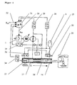
Figur 3 zeigt eine weitere vorteilhafte Ausführung einer
erfindungsgemässen Vorrichtung. Die Maschinenachse ist hier
als Einspritzeinheit 20 einer Spritzgiessmaschine ausgebildet
und muss sehr hohe Kräfte und Leistungen in Richtung X
aufbringen, um den Kunststoff unter hohem Druck in das
Werkzeug einer nicht gezeichneten Maschine zu pressen. Nach
dem Einspritzvorgang muss die Einspritzeinheit bei praktisch
verschwindenden Kräften wieder in die Ausgangslage zurückgefahren
werden.Figure 3 shows a further advantageous embodiment of a
device according to the invention. The machine axis is here
formed as an
Dieser asymmetrischen Aufgabe entspricht auch eine asymmetrische
Auslegung der erfindungsgemässen Vorrichtung.
Wählt man ein verhältnismässig hohes Druckniveau im Speicher
9 und einen verhältnismässig grossen Querschnitt der Zylinderkammer
15, so verschiebt sich der Kraftbereich der Vorrichtung
hin zu positiven Kräften in Richtung X bei entsprechend
verringerten Kräften in die Gegenrichtung.This asymmetrical task also corresponds to an asymmetrical one
Design of the device according to the invention.
If you choose a relatively high pressure level in the
Im Extremfall kann der Speicher 8 weggelassen werden. Bei
geeigneter Auslegung der Vorrichtung wird das volle Moment
des Motors 2 benötigt, um die Kolbenstange 21 in die Ausgangslage
vor dem Einspritzvorgang zu bringen oder in dieser
Position zu halten. Beim anschliessenden Einspritzvorgang
arbeiten Motor 2, Pumpe 3 und Druckspeicher 9 in die gleiche
Richtung. Auf diese Weise addieren sich die Leistungen von
Druckspeicher und Pumpe.In extreme cases, the
Es ist leicht einzusehen, daß sich auf diese Weise die Leistung der eingesetzten Motor-Pumpengruppe verdoppeln lässt. Dies lässt sich in höhere Kräfte oder eine höhere Beschleunigung des Antriebes umsetzen. Diese Ausführungsform einer erfindungsgemässen Vorrichtung eignet sich also besonders in Maschinen, die sehr hohe Kräfte oder Beschleunigungen in nur eine Richtung erreichen müssen.It is easy to see that the Double the output of the motor-pump group used leaves. This can be translated into higher forces or a higher one Implement acceleration of the drive. This embodiment a device according to the invention is therefore particularly suitable in machines that have very high forces or accelerations have to reach in one direction only.
Die Ventile 23, 24 stellen ein weiteres spezielles Element
einer erfindungsgemässen Vorrichtung dar. Die Ventilmagnete
25,26 schalten die Ventile 23,24 und verbinden damit die
Druckspeicher 8,9 mit je einer Druckleitung der Pumpe. Auf
diese Weise ist der Vorspanndruck in den Druckspeichern 8,9
veränderbar. Die Versorgung der Ventile kann dabei auch
durch eine andere, unabhängige Druckquelle erfolgen. Neben
dem Vorspanndruck kann mit dieser Einrichtung natürlich auch
die neutrale Lage eingestellt werden. Unter neutraler Lage
ist die Lage der Kolbenstange 21, bei der sich die Druckkräfte
der Speicher 8,9 neutralisieren, zu verstehen.The
Figur 4 zeigt eine etwas abgewandelte Form einer erfindungsgemässen
Vorrichtung zum Antrieb eines Kniehebelmechanismus
20. Es wird nur noch ein einziger Zylinder 10 eingesetzt. FIG. 4 shows a somewhat modified form of an inventive one
Device for driving a
Pumpe 3 und Druckspeicher 8,9 werden dabei nicht mehr parallel
geschaltet wie in den Figuren 1 bis 3, sondern hintereinander
(in Serie). Entsprechend werden nur noch zwei
Zylinderkammern 14,16 benötigt.
Die Funktion der Vorrichtung wird dadurch allerdings nicht
verändert. Auch so lässt sich ein hydraulischer Oszillator
mit den in den vorhergehenden Abschnitten beschriebenen
Eigenschaften realisieren. Fördert die Pumpe Öl von der
Zylinderkammer 16 in den Druckspeicher 8, so erhöht sich der
Druck im Speicher 8 und die Kolbenstange 17 verschiebt sich
in Richtung X, getrieben durch die Druckkräfte in der Kammer
14. Diese Druckkräfte werden dadurch reduziert. In der Summe
wirkt die ganze Vorrichtung wieder wie ein Feder-Masse-Schwinger,
der auch ohne äussere Kräfte eine zyklische
Bewegung (Eigenschwingung) ausführen kann.However, the function of the device is not thereby
changed. A hydraulic oscillator can also be used in this way
with those described in the previous sections
Realize properties. The pump delivers oil from the
Ein weiteres besonderes Merkmal der erfindungsgemässen
Vorrichtung in Figur 4 besteht in der zweiten Pumpengruppe
bestehend aus Motor 13, Pumpe 11 und Druckbegrenzungsventil
15. Diese Einheit erzeugt einen konstanten Druck auf den
Rückschlagventilen 5,6 und sorgt dafür, daß der Druck in den
Druckspeichern 8,9 einen voreingestellten Mimimalwert nicht
unterschreitet. Die Pumpengruppe ersetzt auch Lecköl der
Pumpe 3, welches durch die Leckölleitung 4 in den Tank 7
gelangt.Another special feature of the invention
The device in FIG. 4 consists of the second pump group
consisting of
In Figur 5 ist die Maschinenachse 20 als Drehgelenk ausgebildet.
Die erfindungsgemässe Vorrichtung entspricht dabei
weitgehend der Vorrichtung in Figur 2. Die Druckspeicher 8,9
in Figur 2 sind allerdings durch einen einzigen Druckspeicher
8 ersetzt, der beide Ventile 24,25 mit Drucköl versorgt.In FIG. 5, the
Zusätzlich wurden in Figur 5 Drucksensoren 28,29,33, ein
Wegmesssystem 34 sowie ein Steuerrechner 31 eingezeichnet.
Diese Elemente wurden in den Figuren 1 bis 4 aus Gründen der
Übersichtlichkeit nicht gezeichnet, ermöglichen aber eine
genauere Regelung der Vorrichtung. Das Wegmesssystem 34 kann
dabei insbesondere auch in dem oder den Zylinder(n) integriert
sein. Neben Druck und Position können auch zeitliche
Ableitungen dieser Grössen erfasst werden.In addition,
Die Signale von Wegmesssystem 34 und Drucksensoren 28,29,33
stehen dem Steuerrechner 31 zur Verfügung, welcher den
Umrichter 1 nach Massgabe eines Regelalgorithmus wie z.B.
einer Zustandsregelung ansteuert. Die Sollbewegung der
Vorrichtung Xset 32 wird dabei von einer übergeordneten
Maschinensteuerung generiert. Dies ermöglicht die Regelung
der Position wie auch der Kraft, welche von der erfindungsgemässen
Vorrichtung auf die Maschinenachse 20 ausgeübt
wird. Der Steuerrechner 31 kann auch im Umrichter oder in
der übergeordneten Maschinensteuerung integriert sein. In
vielen Anwendungen ist es ausreichend den Druck in nur einer
Zylinderkammer 14,15,16,17 zu erfassen.The signals from
Die Verwendung der Vorrichtung ist sehr vielseitig. So kann sie z.B. zum Antrieb jeweils einer Achse eines Krans, einer Presse, einer Umformpresse, einer Biegepresse, einer Schere, einer Streckrichtmaschine, einer Testmaschine, einer Hebebühne, einer Stanzmaschine, einer Spritzgiessmaschine, einer Druckgiessmaschine oder einer anderen Maschine eingesetzt werden. Die Vorrichtung oder Teile davon ist/sind auch für andere Zwecke verwendbar und kann/können nur zeitweise im Sinne der Erfindung eingesetzt werden.The use of the device is very versatile. So can they e.g. to drive one axis of a crane, one Press, a forming press, a bending press, scissors, a straightening machine, a test machine, a lifting platform, a punching machine, an injection molding machine, one Die casting machine or another machine used become. The device or parts thereof is also for other purposes and can only be used temporarily For the purposes of the invention.
Claims (11)
Applications Claiming Priority (2)
| Application Number | Priority Date | Filing Date | Title |
|---|---|---|---|
| CH2842001 | 2001-02-17 | ||
| CH2842001 | 2001-02-17 |
Publications (3)
| Publication Number | Publication Date |
|---|---|
| EP1233191A2 true EP1233191A2 (en) | 2002-08-21 |
| EP1233191A3 EP1233191A3 (en) | 2004-01-02 |
| EP1233191B1 EP1233191B1 (en) | 2005-11-09 |
Family
ID=4484432
Family Applications (1)
| Application Number | Title | Priority Date | Filing Date |
|---|---|---|---|
| EP01128622A Expired - Lifetime EP1233191B1 (en) | 2001-02-17 | 2001-11-30 | Hydraulic oscillator as a machine drive |
Country Status (5)
| Country | Link |
|---|---|
| US (1) | US6647719B2 (en) |
| EP (1) | EP1233191B1 (en) |
| JP (1) | JP2002257102A (en) |
| AT (1) | ATE309471T1 (en) |
| DE (1) | DE50107980D1 (en) |
Cited By (14)
| Publication number | Priority date | Publication date | Assignee | Title |
|---|---|---|---|---|
| DE10349758B3 (en) * | 2003-10-24 | 2005-06-09 | Schuler Pressen Gmbh & Co. Kg | Vertical drive device for reciprocation of machine element e.g. for press die or parts transfer device in multi-stage press, using hydraulic displacement machine |
| WO2007001694A1 (en) | 2005-06-24 | 2007-01-04 | Exxonmobil Chemical Patents Inc. | Functionalized propylene copolymer adheside composition |
| US7951732B2 (en) | 2007-01-26 | 2011-05-31 | Exxonmobil Chemical Patents Inc. | Elastomeric laminates for consumer products |
| WO2011087692A2 (en) | 2009-12-23 | 2011-07-21 | Invista Technologies S.A R.L. | Stretch articles including polyolefin elastic fiber |
| WO2011087695A2 (en) | 2009-12-23 | 2011-07-21 | Invista Technologies S.A R.L. | Polyolefin elastic fiber |
| WO2011087693A2 (en) | 2009-12-23 | 2011-07-21 | Invista Technologies S.A R.1. | Elastic fiber containing an anti-tack additive |
| US8236878B2 (en) | 2007-09-07 | 2012-08-07 | Exxonmobil Chemical Patents Inc. | Composition and manufacture thereof |
| WO2013055496A1 (en) | 2011-10-14 | 2013-04-18 | Exxonmobil Chemical Patents Inc. | Polyolefin-based crosslinked compositions and methods of making them |
| WO2013096532A1 (en) | 2011-12-22 | 2013-06-27 | Exxonmobil Research And Engineering Company | Method for improving engine fuel efficiency |
| US8609772B2 (en) | 2007-10-23 | 2013-12-17 | Exxonmobil Chemical Patents Inc. | Elastic films having improved mechanical and elastic properties and methods for making the same |
| WO2016069089A1 (en) | 2014-10-29 | 2016-05-06 | Exxonmobil Chemical Patents Inc. | Polyolefin adhesive compositions for elastic applications |
| EP3214158A1 (en) | 2008-08-08 | 2017-09-06 | ExxonMobil Chemical Patents Inc. | Improved olefinic copolymer compositions for viscosity modification of motor oil |
| US10041190B2 (en) | 2009-12-23 | 2018-08-07 | Invista North America S.A.R.L. | Fabric including polyolefin elastic fiber |
| WO2019156802A1 (en) | 2018-02-12 | 2019-08-15 | Exxonmobil Chemical Patents Inc. | Metallocene catalyst feed system for solution polymerization process |
Families Citing this family (18)
| Publication number | Priority date | Publication date | Assignee | Title |
|---|---|---|---|---|
| US7176648B2 (en) * | 2004-05-18 | 2007-02-13 | Husky Injection Molding Systems Ltd. | Energy management apparatus and method for injection molding systems |
| JP4115430B2 (en) * | 2004-07-09 | 2008-07-09 | 日精樹脂工業株式会社 | Driving method of production machine |
| US7635136B2 (en) | 2005-06-21 | 2009-12-22 | Jeffrey E. Cole | Truck assembly for a skateboard, wheeled platform, or vehicle |
| WO2007053036A1 (en) * | 2005-10-31 | 2007-05-10 | Chapdrive As | A turbine driven electric power production system and a method for control thereof |
| US7191593B1 (en) * | 2005-11-28 | 2007-03-20 | Northrop Grumman Corporation | Electro-hydraulic actuator system |
| WO2008016518A2 (en) * | 2006-08-02 | 2008-02-07 | Exxonmobil Chemical Patents Inc. | Propylene-based polymer article |
| US20080155975A1 (en) * | 2006-12-28 | 2008-07-03 | Caterpillar Inc. | Hydraulic system with energy recovery |
| US8241753B2 (en) * | 2007-06-04 | 2012-08-14 | Exxonmobil Chemical Patents Inc. | Composite thermoplastic elastomer structures with high adhesion performance and uses for the same |
| US8706192B2 (en) * | 2008-02-16 | 2014-04-22 | Geng Li | Magnetic resonance elastograph system with hydraulic driver |
| WO2009158100A2 (en) * | 2008-06-27 | 2009-12-30 | Exxonmobil Chemical Patents Inc. | High shrinkage propylene-based films |
| US8186154B2 (en) * | 2008-10-31 | 2012-05-29 | Caterpillar Inc. | Rotary flow control valve with energy recovery |
| GB2473054A (en) * | 2009-08-28 | 2011-03-02 | Gm Global Tech Operations Inc | Synchronizer actuator having a piston that delimits three chambers |
| US9151018B2 (en) * | 2011-09-30 | 2015-10-06 | Caterpillar Inc. | Closed-loop hydraulic system having energy recovery |
| DE102012009669B3 (en) * | 2012-05-03 | 2013-08-14 | Hydac Technology Gmbh | Device for saving energy in hydraulically operated equipment |
| KR102288888B1 (en) * | 2017-06-09 | 2021-08-12 | 현대자동차주식회사 | Driving mode changeable small mobility |
| DE102018128318A1 (en) * | 2018-11-13 | 2020-05-14 | Moog Luxembourg S.à.r.l. | Electrohydrostatic actuator system |
| CN112343955A (en) * | 2020-10-29 | 2021-02-09 | 饶英俊 | Vibration excitation type single-rod double-chamber double-piston oil leakage alarm shock absorber |
| DE102022127671A1 (en) | 2022-10-20 | 2024-04-25 | Liebherr-Components Kirchdorf GmbH | Actuator system with oscillating stroke movement |
Citations (1)
| Publication number | Priority date | Publication date | Assignee | Title |
|---|---|---|---|---|
| WO1997005387A1 (en) | 1995-05-16 | 1997-02-13 | Truninger Ag | Device with at least one hydraulic shaft |
Family Cites Families (9)
| Publication number | Priority date | Publication date | Assignee | Title |
|---|---|---|---|---|
| US2699649A (en) * | 1949-07-15 | 1955-01-18 | Kirwan Y Messick | Hydraulic system for power shears and like machines |
| US3855791A (en) * | 1973-08-24 | 1974-12-24 | M Quinto | Reversible motor hydraulic control system |
| US3971215A (en) * | 1974-06-06 | 1976-07-27 | Marion Power Shovel Company, Inc. | Power shovel and crowd system therefor |
| DE2448723A1 (en) * | 1974-10-12 | 1976-04-22 | Maschf Augsburg Nuernberg Ag | IC engine torque convecter unit - has energy storage device in addition to constant-speed governor |
| DE3705642A1 (en) * | 1986-07-02 | 1988-01-14 | Man Nutzfahrzeuge Gmbh | ENERGY STORAGE AND DELIVERY DEVICE |
| US4760697A (en) * | 1986-08-13 | 1988-08-02 | National Research Council Of Canada | Mechanical power regeneration system |
| US5428958A (en) * | 1987-05-19 | 1995-07-04 | Flutron Ab | Electrohydraulic control system |
| JPH0639317B2 (en) * | 1989-09-09 | 1994-05-25 | 株式会社神戸製鋼所 | Displacement suppression mechanism for mobile cranes |
| US5916139A (en) * | 1997-09-16 | 1999-06-29 | My-D Han-D Mfg. Co. Inc. | Hydraulic system and pump |
-
2001
- 2001-11-30 DE DE50107980T patent/DE50107980D1/en not_active Expired - Lifetime
- 2001-11-30 AT AT01128622T patent/ATE309471T1/en not_active IP Right Cessation
- 2001-11-30 EP EP01128622A patent/EP1233191B1/en not_active Expired - Lifetime
-
2002
- 2002-01-24 US US10/056,138 patent/US6647719B2/en not_active Expired - Fee Related
- 2002-01-29 JP JP2002020276A patent/JP2002257102A/en active Pending
Patent Citations (1)
| Publication number | Priority date | Publication date | Assignee | Title |
|---|---|---|---|---|
| WO1997005387A1 (en) | 1995-05-16 | 1997-02-13 | Truninger Ag | Device with at least one hydraulic shaft |
Cited By (15)
| Publication number | Priority date | Publication date | Assignee | Title |
|---|---|---|---|---|
| DE10349758B3 (en) * | 2003-10-24 | 2005-06-09 | Schuler Pressen Gmbh & Co. Kg | Vertical drive device for reciprocation of machine element e.g. for press die or parts transfer device in multi-stage press, using hydraulic displacement machine |
| WO2007001694A1 (en) | 2005-06-24 | 2007-01-04 | Exxonmobil Chemical Patents Inc. | Functionalized propylene copolymer adheside composition |
| US7951732B2 (en) | 2007-01-26 | 2011-05-31 | Exxonmobil Chemical Patents Inc. | Elastomeric laminates for consumer products |
| US8236878B2 (en) | 2007-09-07 | 2012-08-07 | Exxonmobil Chemical Patents Inc. | Composition and manufacture thereof |
| US8609772B2 (en) | 2007-10-23 | 2013-12-17 | Exxonmobil Chemical Patents Inc. | Elastic films having improved mechanical and elastic properties and methods for making the same |
| EP3214158A1 (en) | 2008-08-08 | 2017-09-06 | ExxonMobil Chemical Patents Inc. | Improved olefinic copolymer compositions for viscosity modification of motor oil |
| WO2011087693A2 (en) | 2009-12-23 | 2011-07-21 | Invista Technologies S.A R.1. | Elastic fiber containing an anti-tack additive |
| WO2011087695A2 (en) | 2009-12-23 | 2011-07-21 | Invista Technologies S.A R.L. | Polyolefin elastic fiber |
| WO2011087692A2 (en) | 2009-12-23 | 2011-07-21 | Invista Technologies S.A R.L. | Stretch articles including polyolefin elastic fiber |
| US10041190B2 (en) | 2009-12-23 | 2018-08-07 | Invista North America S.A.R.L. | Fabric including polyolefin elastic fiber |
| US10039855B2 (en) | 2009-12-23 | 2018-08-07 | Invista North America S.A.R.L. | Elastic fiber containing an anti-tack additive |
| WO2013055496A1 (en) | 2011-10-14 | 2013-04-18 | Exxonmobil Chemical Patents Inc. | Polyolefin-based crosslinked compositions and methods of making them |
| WO2013096532A1 (en) | 2011-12-22 | 2013-06-27 | Exxonmobil Research And Engineering Company | Method for improving engine fuel efficiency |
| WO2016069089A1 (en) | 2014-10-29 | 2016-05-06 | Exxonmobil Chemical Patents Inc. | Polyolefin adhesive compositions for elastic applications |
| WO2019156802A1 (en) | 2018-02-12 | 2019-08-15 | Exxonmobil Chemical Patents Inc. | Metallocene catalyst feed system for solution polymerization process |
Also Published As
| Publication number | Publication date |
|---|---|
| JP2002257102A (en) | 2002-09-11 |
| DE50107980D1 (en) | 2005-12-15 |
| US20020112476A1 (en) | 2002-08-22 |
| EP1233191A3 (en) | 2004-01-02 |
| ATE309471T1 (en) | 2005-11-15 |
| EP1233191B1 (en) | 2005-11-09 |
| US6647719B2 (en) | 2003-11-18 |
Similar Documents
| Publication | Publication Date | Title |
|---|---|---|
| EP1233191B1 (en) | Hydraulic oscillator as a machine drive | |
| EP0782671B1 (en) | Device for the controlled driving of at least one hydraulic shaft | |
| EP0873475B1 (en) | Low-loss drive system for a plurality of hydraulic actuators | |
| DE3919823C3 (en) | Injection molding machine with hydraulic consumers | |
| DE102011000473B4 (en) | Pressing machine and method for pressing workpieces | |
| DE102006058630B4 (en) | Electro-hydraulic press main or auxiliary drive device, in particular electro-hydraulic die cushion drive | |
| DE102005038583B4 (en) | Press drive module and method for providing a press series | |
| EP2676036B1 (en) | Pressure-accumulator-free hydraulic drive arrangement for and comprising a consumer, in particular for presses, and method for operating a pressure-accumulator-free hydraulic drive arrangement of said type | |
| EP3443230B1 (en) | Piezo-hydraulic actuator | |
| EP3077674B1 (en) | Hydraulic arrangement | |
| DE102005012876A1 (en) | Method and device for controlling and regulating servo-electric drawing cushions | |
| EP1288507B1 (en) | Low-loss drive system for a hydraulic actuator | |
| DE19646913A1 (en) | A hydraulic press drive unit and a variable capacity swash plate axial piston pump for use with this device | |
| WO2009026893A1 (en) | Drive system for hydraulic presses | |
| EP1754595B1 (en) | Drive module for press and method for providing a range of presses | |
| EP1086802B1 (en) | Press with crankshaft drive for the upper punch unit and operating method | |
| EP0618025B1 (en) | Injection unit | |
| DE4016534C2 (en) | Manipulator for forging machines, in particular multi-ram forging machines | |
| EP1355775B1 (en) | Regulation method for the hydraulic support of an electric drive | |
| DE102004030678B4 (en) | Cushioning device with hybrid drive | |
| DE102018203367A1 (en) | Hydrostatic linear drive | |
| DE102015218578A1 (en) | HYDROSTATIC ADJUSTING DEVICE WITH REDUCED HYSTERESIS | |
| DE4410719A1 (en) | Electrohydraulically adjustable pump | |
| DE10219581B4 (en) | Drive for a press ram | |
| DE202011103604U1 (en) | Linear drive system with a dual-medium working cylinder |
Legal Events
| Date | Code | Title | Description |
|---|---|---|---|
| PUAI | Public reference made under article 153(3) epc to a published international application that has entered the european phase |
Free format text: ORIGINAL CODE: 0009012 |
|
| AK | Designated contracting states |
Kind code of ref document: A2 Designated state(s): AT BE CH CY DE DK ES FI FR GB GR IE IT LI LU MC NL PT SE TR |
|
| AX | Request for extension of the european patent |
Free format text: AL;LT;LV;MK;RO;SI |
|
| PUAL | Search report despatched |
Free format text: ORIGINAL CODE: 0009013 |
|
| AK | Designated contracting states |
Kind code of ref document: A3 Designated state(s): AT BE CH CY DE DK ES FI FR GB GR IE IT LI LU MC NL PT SE TR |
|
| AX | Request for extension of the european patent |
Extension state: AL LT LV MK RO SI |
|
| 17P | Request for examination filed |
Effective date: 20040528 |
|
| 17Q | First examination report despatched |
Effective date: 20040728 |
|
| AKX | Designation fees paid |
Designated state(s): AT BE CH CY DE DK ES FI FR GB GR IE IT LI LU MC NL PT SE TR |
|
| GRAP | Despatch of communication of intention to grant a patent |
Free format text: ORIGINAL CODE: EPIDOSNIGR1 |
|
| GRAS | Grant fee paid |
Free format text: ORIGINAL CODE: EPIDOSNIGR3 |
|
| GRAA | (expected) grant |
Free format text: ORIGINAL CODE: 0009210 |
|
| AK | Designated contracting states |
Kind code of ref document: B1 Designated state(s): AT BE CH CY DE DK ES FI FR GB GR IE IT LI LU MC NL PT SE TR |
|
| PG25 | Lapsed in a contracting state [announced via postgrant information from national office to epo] |
Ref country code: FI Free format text: LAPSE BECAUSE OF FAILURE TO SUBMIT A TRANSLATION OF THE DESCRIPTION OR TO PAY THE FEE WITHIN THE PRESCRIBED TIME-LIMIT Effective date: 20051109 Ref country code: TR Free format text: LAPSE BECAUSE OF FAILURE TO SUBMIT A TRANSLATION OF THE DESCRIPTION OR TO PAY THE FEE WITHIN THE PRESCRIBED TIME-LIMIT Effective date: 20051109 Ref country code: NL Free format text: LAPSE BECAUSE OF FAILURE TO SUBMIT A TRANSLATION OF THE DESCRIPTION OR TO PAY THE FEE WITHIN THE PRESCRIBED TIME-LIMIT Effective date: 20051109 Ref country code: IT Free format text: LAPSE BECAUSE OF FAILURE TO SUBMIT A TRANSLATION OF THE DESCRIPTION OR TO PAY THE FEE WITHIN THE PRESCRIBED TIME-LIMIT;WARNING: LAPSES OF ITALIAN PATENTS WITH EFFECTIVE DATE BEFORE 2007 MAY HAVE OCCURRED AT ANY TIME BEFORE 2007. THE CORRECT EFFECTIVE DATE MAY BE DIFFERENT FROM THE ONE RECORDED. Effective date: 20051109 |
|
| REG | Reference to a national code |
Ref country code: GB Ref legal event code: FG4D Free format text: NOT ENGLISH |
|
| REG | Reference to a national code |
Ref country code: CH Ref legal event code: NV Representative=s name: E. BLUM & CO. PATENTANWAELTE Ref country code: CH Ref legal event code: EP |
|
| PG25 | Lapsed in a contracting state [announced via postgrant information from national office to epo] |
Ref country code: MC Free format text: LAPSE BECAUSE OF NON-PAYMENT OF DUE FEES Effective date: 20051130 Ref country code: CY Free format text: LAPSE BECAUSE OF FAILURE TO SUBMIT A TRANSLATION OF THE DESCRIPTION OR TO PAY THE FEE WITHIN THE PRESCRIBED TIME-LIMIT Effective date: 20051130 |
|
| REG | Reference to a national code |
Ref country code: IE Ref legal event code: FG4D Free format text: LANGUAGE OF EP DOCUMENT: GERMAN |
|
| REF | Corresponds to: |
Ref document number: 50107980 Country of ref document: DE Date of ref document: 20051215 Kind code of ref document: P |
|
| PG25 | Lapsed in a contracting state [announced via postgrant information from national office to epo] |
Ref country code: DK Free format text: LAPSE BECAUSE OF FAILURE TO SUBMIT A TRANSLATION OF THE DESCRIPTION OR TO PAY THE FEE WITHIN THE PRESCRIBED TIME-LIMIT Effective date: 20060209 Ref country code: SE Free format text: LAPSE BECAUSE OF FAILURE TO SUBMIT A TRANSLATION OF THE DESCRIPTION OR TO PAY THE FEE WITHIN THE PRESCRIBED TIME-LIMIT Effective date: 20060209 Ref country code: GR Free format text: LAPSE BECAUSE OF FAILURE TO SUBMIT A TRANSLATION OF THE DESCRIPTION OR TO PAY THE FEE WITHIN THE PRESCRIBED TIME-LIMIT Effective date: 20060209 |
|
| PG25 | Lapsed in a contracting state [announced via postgrant information from national office to epo] |
Ref country code: ES Free format text: LAPSE BECAUSE OF FAILURE TO SUBMIT A TRANSLATION OF THE DESCRIPTION OR TO PAY THE FEE WITHIN THE PRESCRIBED TIME-LIMIT Effective date: 20060220 |
|
| GBT | Gb: translation of ep patent filed (gb section 77(6)(a)/1977) |
Effective date: 20060214 |
|
| PG25 | Lapsed in a contracting state [announced via postgrant information from national office to epo] |
Ref country code: PT Free format text: LAPSE BECAUSE OF FAILURE TO SUBMIT A TRANSLATION OF THE DESCRIPTION OR TO PAY THE FEE WITHIN THE PRESCRIBED TIME-LIMIT Effective date: 20060410 |
|
| NLV1 | Nl: lapsed or annulled due to failure to fulfill the requirements of art. 29p and 29m of the patents act | ||
| ET | Fr: translation filed | ||
| PLBE | No opposition filed within time limit |
Free format text: ORIGINAL CODE: 0009261 |
|
| STAA | Information on the status of an ep patent application or granted ep patent |
Free format text: STATUS: NO OPPOSITION FILED WITHIN TIME LIMIT |
|
| 26N | No opposition filed |
Effective date: 20060810 |
|
| REG | Reference to a national code |
Ref country code: CH Ref legal event code: PFA Owner name: GLOBEMAG L.P. Free format text: GLOBEMAG L.P.#40 MELVILLE STREET#EDINBURGH EH3 7TW (GB) -TRANSFER TO- GLOBEMAG L.P.#40 MELVILLE STREET#EDINBURGH EH3 7TW (GB) |
|
| PGFP | Annual fee paid to national office [announced via postgrant information from national office to epo] |
Ref country code: IE Payment date: 20071122 Year of fee payment: 7 |
|
| REG | Reference to a national code |
Ref country code: IE Ref legal event code: MM4A |
|
| PG25 | Lapsed in a contracting state [announced via postgrant information from national office to epo] |
Ref country code: IE Free format text: LAPSE BECAUSE OF NON-PAYMENT OF DUE FEES Effective date: 20081201 |
|
| PGFP | Annual fee paid to national office [announced via postgrant information from national office to epo] |
Ref country code: AT Payment date: 20091113 Year of fee payment: 9 Ref country code: CH Payment date: 20091124 Year of fee payment: 9 Ref country code: LU Payment date: 20091120 Year of fee payment: 9 |
|
| PGFP | Annual fee paid to national office [announced via postgrant information from national office to epo] |
Ref country code: FR Payment date: 20091201 Year of fee payment: 9 Ref country code: GB Payment date: 20091119 Year of fee payment: 9 |
|
| PGFP | Annual fee paid to national office [announced via postgrant information from national office to epo] |
Ref country code: BE Payment date: 20091224 Year of fee payment: 9 Ref country code: DE Payment date: 20091228 Year of fee payment: 9 |
|
| BERE | Be: lapsed |
Owner name: *GLOBEMAG L.P. Effective date: 20101130 |
|
| REG | Reference to a national code |
Ref country code: CH Ref legal event code: PL |
|
| GBPC | Gb: european patent ceased through non-payment of renewal fee |
Effective date: 20101130 |
|
| PG25 | Lapsed in a contracting state [announced via postgrant information from national office to epo] |
Ref country code: LI Free format text: LAPSE BECAUSE OF NON-PAYMENT OF DUE FEES Effective date: 20101130 Ref country code: CH Free format text: LAPSE BECAUSE OF NON-PAYMENT OF DUE FEES Effective date: 20101130 |
|
| REG | Reference to a national code |
Ref country code: FR Ref legal event code: ST Effective date: 20110801 |
|
| PG25 | Lapsed in a contracting state [announced via postgrant information from national office to epo] |
Ref country code: AT Free format text: LAPSE BECAUSE OF NON-PAYMENT OF DUE FEES Effective date: 20101130 Ref country code: BE Free format text: LAPSE BECAUSE OF NON-PAYMENT OF DUE FEES Effective date: 20101130 |
|
| REG | Reference to a national code |
Ref country code: DE Ref legal event code: R119 Ref document number: 50107980 Country of ref document: DE Effective date: 20110601 Ref country code: DE Ref legal event code: R119 Ref document number: 50107980 Country of ref document: DE Effective date: 20110531 |
|
| PG25 | Lapsed in a contracting state [announced via postgrant information from national office to epo] |
Ref country code: FR Free format text: LAPSE BECAUSE OF NON-PAYMENT OF DUE FEES Effective date: 20101130 |
|
| PG25 | Lapsed in a contracting state [announced via postgrant information from national office to epo] |
Ref country code: GB Free format text: LAPSE BECAUSE OF NON-PAYMENT OF DUE FEES Effective date: 20101130 |
|
| PG25 | Lapsed in a contracting state [announced via postgrant information from national office to epo] |
Ref country code: LU Free format text: LAPSE BECAUSE OF NON-PAYMENT OF DUE FEES Effective date: 20101130 |
|
| PG25 | Lapsed in a contracting state [announced via postgrant information from national office to epo] |
Ref country code: DE Free format text: LAPSE BECAUSE OF NON-PAYMENT OF DUE FEES Effective date: 20110531 |