EP1233475A2 - Terminal structure of connector - Google Patents
Terminal structure of connector Download PDFInfo
- Publication number
- EP1233475A2 EP1233475A2 EP02003447A EP02003447A EP1233475A2 EP 1233475 A2 EP1233475 A2 EP 1233475A2 EP 02003447 A EP02003447 A EP 02003447A EP 02003447 A EP02003447 A EP 02003447A EP 1233475 A2 EP1233475 A2 EP 1233475A2
- Authority
- EP
- European Patent Office
- Prior art keywords
- male tab
- contact
- spring contact
- male
- point
- Prior art date
- Legal status (The legal status is an assumption and is not a legal conclusion. Google has not performed a legal analysis and makes no representation as to the accuracy of the status listed.)
- Granted
Links
Images


Classifications
-
- H—ELECTRICITY
- H01—ELECTRIC ELEMENTS
- H01R—ELECTRICALLY-CONDUCTIVE CONNECTIONS; STRUCTURAL ASSOCIATIONS OF A PLURALITY OF MUTUALLY-INSULATED ELECTRICAL CONNECTING ELEMENTS; COUPLING DEVICES; CURRENT COLLECTORS
- H01R13/00—Details of coupling devices of the kinds covered by groups H01R12/70 or H01R24/00 - H01R33/00
- H01R13/02—Contact members
- H01R13/10—Sockets for co-operation with pins or blades
- H01R13/11—Resilient sockets
Definitions
- the present invention relates to a terminal structure of a connector including a female terminal having a tongue-piece-shaped spring contact disposed in a fitting portion thereof and a male terminal to be inserted into the fitting portion of the female terminal to contact with the spring contact.
- a connector including a female terminal having a tongue-piece-shaped spring contact disposed in a fitting portion thereof and a male terminal having a male tab to be inserted into the fitting portion of the female terminal to contact with the spring contact; that is, by connecting together the male and female terminals, the wire harnesses can be electrically connected to each other.
- a fixed contact 5 which can contact with one surface of the male tab 3, and a spring contact 6a, opposed to the fixed contact 5 with a given initial clearance.
- the male tab 3 is inserted between the two contacts 5, 6a and deforms the spring contact 6a elastically. While the spring contact 6a is elastically deformed in this manner, the male tab 3 contacts the two contacts 5, 6a to electrically connect a harness fixed to the female terminal 2 to a harness fixed to the male terminal 4.
- the initial clearance formed between the two contacts 5, 6a of the female terminal 2 is set at a value smaller by a given amount than the thickness of the male tab 3. Therefore, as the male tab 3 of the male terminal 4 is inserted into between the two contacts 5, 6a, the spring contact 6a is greatly deformed elastically to rapidly increase its contact reaction force. At the same time, as shown by a broken line in Fig. 7, just after the male tab 3 is inserted, the insertion force Fa of the male terminal 4 with respect to the female terminal 2 rises suddenly up to its peak value. Thereafter, the insertion force Fa decreases by a given amount, thereby bringing the two terminals 2, 4 into a connection-completed state.
- the present invention aims at eliminating the above-described problems. Accordingly, it is an object of the invention to provide a terminal structure of a connector which can reduce effectively the insertion force of a male tab with respect to the fitting portion of a female terminal without impairing the connection reliability of the connector.
- a terminal structure of a connector including a female terminal, having a spring contact, e.g., a tongue-piece-shaped spring contact, in a fitting portion thereof, and a male terminal, having a male tab to be inserted into the fitting portion of the female terminal and contacted by the spring contact.
- the contact reaction force of the spring contact can be set at a sufficiently high value, while preventing the insertion force of the male tab from suddenly increasing up to its peak value.
- the terminal structure of the connector according to the first aspect of the invention, wherein during the interval between a point of initial contact between the male tab and the spring contact and a point just before the insertion force of the male tab reaches its peak value, the contact angle ⁇ L of the male tab with respect to the spring contact, and the friction coefficient ⁇ between the surface of the male tab and the surface of the spring contact satisfy the following relational expression:
- the peak value of the insertion force of the male tab can be reduced more effectively and also the contact reaction force of the spring contact can be set at a sufficiently high value.
- the terminal structure of the connector according to the first aspect of the invention wherein during the interval between a point of initial contact between the male tab and the spring contact and a point just before the insertion force of the male tab reaches its peak value, the contact angle ⁇ L of the male tab with respect to the spring contact, and the friction coefficient ⁇ between the surface of the male tab and the surface of the spring contact satisfy the following relational expression: 90°> ⁇ L ⁇ 53.74° ⁇ +59.537°
- the peak value of the insertion force which is generated when the male tab is fitted into the fitting portion of the female terminal to connect the male and female terminals together, can be kept down to about 60% or less of the contact reaction force of the spring contact in the connection-completed state of the terminals.
- the terminal structure of the connector according to the second aspect of the invention wherein during the interval between a point of initial contact between the male tab and the spring contact and a point just before the insertion force of the male tab reaches its peak value, the contact angle ⁇ L of the male tab with respect to the spring contact, and the friction coefficient ⁇ between the surface of the male tab and the surface of the spring contact satisfy the following relational expression: 90°> ⁇ L ⁇ 53.74° ⁇ +63.936°.
- the peak value of the insertion force which is generated when the male tab is fitted into the fitting portion of the female terminal to connect the male and female terminals together, can be kept down to about 50% or less of the contact reaction force of the spring contact in the connection-completed state of the terminals.
- the terminal structure of the connector according to the first aspect of the invention wherein during the interval between a point of initial contact between the male tab and the spring contact and a point just before the insertion force of the male tab reaches its peak value, the contact angle ⁇ L of the male tab with respect to the spring contact is in a range of: 90°> ⁇ L ⁇ 67.5°.
- the peak value of the insertion force which is generated when the male tab is fitted into the fitting portion of the female terminal to connect together the male and female terminals, can be kept down to about 60% or less of the contact reaction force of the spring contact in the connection-completed state of the terminals.
- the terminal structure of the connector according to the second aspect of the invention wherein during the interval between a point of initial contact between the male tab and the spring contact and a point just before the insertion force of the male tab reaches its peak value, the contact angle ⁇ L of the male tab with respect to the spring contact is in a range of: 90°> ⁇ L ⁇ 71.9°
- the peak value of the insertion force which is generated when the male tab is fitted into the fitting portion of the female terminal to connect together the male and female terminals, can be kept down to about 50% or less of the contact reaction force of the spring contact in the connection-completed state of the terminals.
- a seventh aspect of the invention there is provided the terminal structure of the connector according to any one of the first to sixth aspects of the invention, wherein a forwardly-tapered inclined surface is formed at a leading end portion of the male tab.
- a base end portion of the inclined surface contacts the spring contact.
- the contact angle of the male tab is not decided in accordance with the inclination angle of the inclined surface.
- the contact angle ⁇ L of the male tab with respect to the spring contact of the female terminal can be set at a proper value, regardless of the inclination angle of the inclined surface.
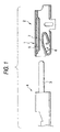
- Figs. 1 and 2 show an embodiment of a terminal structure of a connector according to the invention.
- This connector includes a female terminal 2 having a fitting portion 1, which may have a cylindrical shape or other suitable shape, and a male terminal 4 including a male tab 3 to be inserted into the fitting portion 1 of the female terminal 2.
- a harness (not shown) fixed to a rear end portion of the female terminal 2 can be electrically connected to a harness (not shown) fixed to a rear end portion of the male terminal 4.
- a spring contact 6 situated upwardly of a bottom wall portion of the fitting portion 1.
- a fixed contact 5 mounted on a lower surface of a ceiling portion of the fitting portion 1, opposed to the spring contact 6 with a given initial clearance therebetween.
- the spring contact 6 is preferably formed by, for example, bending or folding upwardly a plate-shaped member which is disposed on and extended continuously from a front end of the bottom wall portion of the fitting portion 1.
- the inclination angle of the spring contact 6 with respect to a longitudinal axis of the female terminal 2 is set smaller than that of the spring contact employed in the related art.
- the contact portion 7 swells out upwardly over a given range of the spring contact 6, from the vicinity of the front end portion of the spring contact 6 to the vicinity of the rear end portion thereof, in a gentle curve.
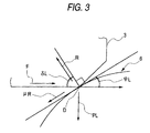
- ⁇ L expresses the inclination angle of the spring contact 6, with respect to a longitudinal axis (i.e., axis of insertion) of the female terminal 2, at the contact point of the male tab 3. That is, ⁇ L expresses the angle formed between the insertion direction of the male tab 3 and the above-mentioned tangential direction.
- ⁇ L 90° - ⁇ L
- the present inventors conducted various tests. According to the tests, it was confirmed that, when the following conditional expression (5) was satisfied between the insertion force F and the contact reaction force PL, the connection reliability of the connector could be ensured without fatiguing the operator: 0 ⁇ F ⁇ 0.6 PL
- the two terminals are structured such that, when the male tab 3 of the male terminal 4 is inserted into the fitting portion 1 of the female terminal 2 to connect together the two terminals 2, 4, during the interval between a point of initial contact between the male tab and the spring contact and a point just before the insertion force of the male tab reaches its peak value, the contact angle ⁇ L of the male tab 3 with respect to the spring contact 6, and the friction coefficient ⁇ between the surface of the male tab 3 and the surface of the spring contact 6 satisfy the relational expression (8), that is, the relationship,
- the insertion force F can be kept down to 60% or less of the contact reaction force PL, and thus the connection reliability of the connector can be ensured without imposing any extra burden on the operator.
- the friction coefficient ⁇ is in a range of from about 0.1 to about 0.4
- the lower limit values of the contact angles ⁇ L existing in this range can be calculated in accordance with the relational expression (8).
- the resultant values are shown in a graphic form, they can be expressed by a line A shown in Fig. 4.
- Fig. 4 shows that, when the male tab 3 of the male terminal 4 is inserted into the fitting portion 1 of the female terminal 2 to connect the two terminals 2, 4 together, in a case in which, during the interval between a point of initial contact between the male tab and the spring contact and a point just before the insertion force of the male tab reaches its peak value, the contact angle ⁇ L of the male tab 3 with respect to the spring contact 6, and the friction coefficient ⁇ between the surface of the male tab 3 and the surface of the spring contact 6 meet the following expression (9), the connection reliability of the connector can be ensured without imposing any extra burden on the operator. 90°> ⁇ L ⁇ 53.74 ⁇ + 59.537°
- the two terminals are structured so that when the male tab 3 of the male terminal 4 is inserted into the fitting portion 1 of the female terminal 2 to connect together the two terminals 2, 4, during the interval between a point of initial contact between the male tab and the spring contact and a point just before the insertion force of the male tab reaches its peak value, the contact angle ⁇ L of the male tab 3 with respect to the spring contact 6, and the friction coefficient ⁇ between the surface of the male tab 3 and the surface of the spring contact 6 satisfy the relational expression
- the insertion force F can be kept down to 50% or less of the contact reaction force PL, and the connection reliability of the connector can be sufficiently ensured while further reducing the burden on the operator.
- the friction coefficient ⁇ is in a range of from about 0.1 to about 0.4 and the lower limit values of the contact angles ⁇ L are calculated in accordance with the relational expression (8) to show the resultant values in a graphic form, they can be expressed by a line B shown in Fig. 4.
- the following relational expression (9a) can be obtained and, especially, in a case of a friction coefficient ⁇ of 0.15 or more, the following relational expression (10a) can be obtained: 90°> ⁇ L ⁇ 53.74° ⁇ +63.936° 90° > ⁇ L ⁇ 71.9°
- the two terminals are structured so that when the male tab 3 of the male terminal 4 is inserted into the fitting portion 1 of the female terminal 2 to connect the two terminals 2, 4 together, during the interval between a point of initial contact between the male tab and the spring contact and a point just before the insertion force of the male tab reaches its peak value, the contact angle ⁇ L of the male tab 3 with respect to the spring contact 6, and the friction coefficient ⁇ between the surface of the male tab 3 and the surface of the spring contact 6 satisfy the relational expression (9a), that is, 90°> ⁇ L ⁇ 53.74° ⁇ +63.936°.
- the insertion force F can be kept down to 50% or less of the contact reaction force PL, and the connection reliability of the connector can be sufficiently ensured while further reducing the burden on the operator.
- the friction coefficient ⁇ is 0.15 or more
- the contact angle ⁇ L of the male tab 3 with respect to the spring contact 6 is 71.9° or more.
- the contact position of the male tab 3 with respect to the spring contact 6 of the female terminal 2 varies sequentially according to the insertion amount of the male tab 3. For example, when the male tab 3 is inserted by a given distance ⁇ h from an initial contact position H shown by a solid line in Fig. 5 into the fitting portion 1 of the female terminal 2, the contact position of the male tab 3 with respect to the spring contact 6 shifts to a position C shown by a broken line in Fig. 5, that is, this contact position C is lowered by a distance ⁇ v from its initial position C'.
- a horizontal distance and a vertical distance from a base end portion G (turned-back end portion) of the spring contact 6 to the initial contact position H of the male tab 3 are expressed as ⁇ h and ⁇ v, respectively, and the inclination angle of the spring contact 6 with respect to a longitudinal axis of the female terminal 2, in the initial contact state of the male tab 3 with respect to the spring contact 6, is expressed as ⁇ .
- relational expression (11) is substituted for the relational expression (12)
- relational expression (13) is obtained.
- relational expression (13) is substituted for the above-mentioned relational expression (4), as shown in the following relational expression (14), a relational expression can be obtained among the insertion force F of the connector, the contact reaction force PL, the insertion position of the male tab 3 ( ⁇ h + ⁇ h), the inclination angle ⁇ L, and the friction coefficient ⁇ between the surface of the male tab and the surface of the spring contact.
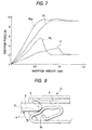
- a verification test was performed to compare an embodiment according to the invention, in which the contact angle ⁇ L at the initial contact position between the male tab 3 and the spring contact 6 is set at an angle of 76.4°, and the above-described related art example, in which the contact angle is set at an angle of 66.3°.
- the relational expressions (13), (14) it was verified how the insertion forces F (embodiment) and Fa (related art) of the connector and the contact reaction forces PL (embodiment) and PLa (related art) of the spring contact 6 vary according to the insertion amount of the male tab 3. From the verification test, such data as shown in Fig. 7 are obtained.
- the peak value of the insertion force Fa is about 5.7.
- the insertion force F reaches its peak value of about 3.5 N just before the connector connection is completed. Therefore, as described above, although the contact reaction forces PL (embodiment) and PLa (related art) in the connection-completed state of the connector were set at the same value, respectively, it was confirmed that, in the embodiment according to the invention, the peak value of the insertion force F can be reduced by about 38.6% in comparison with the related art.
- the connector is structured so that with respect to the inclination angle ⁇ T of the inclined surface 3a formed at the leading end portion of the male tab 3, the angle of 90° - ⁇ T is set in a range of from about 67.5° to 90°, or in a range of from about 71.9° to 90°, and the inclined surface 3a contacts the spring contact 6 when the male tab 3 is inserted into the fitting portion 1 of the female terminal 2.
- the contact angle ⁇ L of the male tab 3 with respect to the spring contact 6 can remain in the range of 90° > ⁇ L ⁇ 67.5°, or 90° > ⁇ L ⁇ 71.9°.
- the inclination angle ⁇ T of the inclined surface 3a may be set so that the base end portion D of the inclined surface 3a is the part that initially contacts the spring contact 6 when the male tab 3 is inserted into the fitting portion 1 of the female terminal 2 (see Fig. 5).
- the contact angle ⁇ L at the time of insertion of the male tab 3 with respect to the spring contact 6 of the female terminal 2 is not decided by the inclined surface 3a.
- the contact angle ⁇ L can be set at a proper value according to the set angle of the spring contact 6 and the shape of the contact portion 7.
- the leading end portion of the male tab 3 is formed as a flat surface, as shown by a broken line d in Fig. 8, the leading end portion of the male tab 3 and the spring contact 6 contact each other in a point contact manner and, therefore, the contact angle ⁇ L is always set in accordance with the inclination angle ⁇ L of the spring contact 6.
- a terminal structure of a connector including a female terminal having a spring contact in a fitting portion thereof, and a male terminal having a male tab to be inserted into the fitting portion of the female terminal and contacted by the spring contact.
- the contact angle ⁇ L of the male tab with respect to the spring contact, and the friction coefficient ⁇ between the surface of the male tab and the surface of the spring contact satisfy the following relational expression:
Abstract
Description


Claims (9)
- A terminal structure of a connector, comprising:wherein when the male tab is fitted into the fitting portion of the female terminal, during the interval between a point of initial contact between the male tab and the spring contact and a point just before an insertion force of the male tab reaches a peak value, a contact angle δL of the male tab with respect to the spring contact, and a friction coefficient µ between a surface of the male tab and a surface of the spring contact satisfy the following relational expression:a female terminal having a spring contact in a fitting portion thereof; anda male terminal having a male tab to be inserted into the fitting portion of the female terminal and contacted by the spring contact,

- The terminal structure according to claim 1, wherein during the interval between the point of initial contact between the male tab and the spring contact and the point just before the insertion force of the male tab reaches the peak value, the contact angle δL of the male tab with respect to the spring contact, and the friction coefficient µ between the surface of the male tab and the surface ofthe spring contact satisfy the following relational expression:
- The terminal structure according to claim 1, wherein during the interval between the point of initial contact between the male tab and the spring contact and the point just before the insertion force of the male tab reaches the peak value, the contact angle δL of the male tab with respect to the spring contact is in a range of 90° > δL ≥ 67.5°.
- The terminal structure according to claim 1, wherein during the interval between the point of initial contact between the male tab and the spring contact and the point just before the insertion force of the male tab reaches the peak value, the contact angle δL of the male tab with respect to the spring contact, and the friction coefficient µ between the surface of the male tab and the surface of the spring contact satisfy the following relational expression:

- The terminal structure according to claim 4, wherein during the interval between the point of initial contact between the male tab and the spring contact and the point just before the insertion force of the male tab reaches the peak value, the contact angle δL of the male tab with respect to the spring contact, and the friction coefficient µ between the surface of the male tab and the surface of the spring contact satisfy the following relational expression:
- The terminal structure according to claim 4, wherein during the interval between the point of initial contact between the male tab and the spring contact and the point just before the insertion force of the male tab reaches the peak value, the contact angle δL of the male tab with respect to the spring contact is in a range of 90° > δL ≥ 71.9°.
- The terminal structure according to claim 1, wherein a forwardly-tapered inclined surface is formed at a leading end portion of the male tab.
- The terminal structure according to claim 7, wherein when the male tab is fitted into the fitting portion of the female terminal, an initial contact between the male tab and the spring contact is a contact between a base end portion of the inclined surface and the spring contact.
- The terminal structure according to claim 7, wherein when the male tab is fitted into the fitting portion of the female terminal, an initial contact between the male tab and the spring contact is a contact between the inclined surface and the spring contact.
Applications Claiming Priority (2)
| Application Number | Priority Date | Filing Date | Title |
|---|---|---|---|
| JP2001038876A JP4401580B2 (en) | 2001-02-15 | 2001-02-15 | Connector terminal structure |
| JP2001038876 | 2001-02-15 |
Publications (3)
| Publication Number | Publication Date |
|---|---|
| EP1233475A2 true EP1233475A2 (en) | 2002-08-21 |
| EP1233475A3 EP1233475A3 (en) | 2003-10-01 |
| EP1233475B1 EP1233475B1 (en) | 2007-03-28 |
Family
ID=18901779
Family Applications (1)
| Application Number | Title | Priority Date | Filing Date |
|---|---|---|---|
| EP02003447A Expired - Lifetime EP1233475B1 (en) | 2001-02-15 | 2002-02-14 | Terminal structure of connector |
Country Status (4)
| Country | Link |
|---|---|
| US (1) | US6506084B2 (en) |
| EP (1) | EP1233475B1 (en) |
| JP (1) | JP4401580B2 (en) |
| DE (1) | DE60219091T2 (en) |
Cited By (1)
| Publication number | Priority date | Publication date | Assignee | Title |
|---|---|---|---|---|
| EP3301762A1 (en) * | 2016-09-29 | 2018-04-04 | Delphi Technologies, Inc. | Electrical connection system having a terminal with contact ridges |
Families Citing this family (15)
| Publication number | Priority date | Publication date | Assignee | Title |
|---|---|---|---|---|
| JP4498721B2 (en) * | 2003-11-05 | 2010-07-07 | 株式会社オートネットワーク技術研究所 | Connector manufacturing method |
| US20060292937A1 (en) * | 2005-06-23 | 2006-12-28 | Morello John R | Electrical connector having dual contact function spring contact terminal |
| JP4722707B2 (en) * | 2005-10-13 | 2011-07-13 | 日本圧着端子製造株式会社 | Vertical mating female terminal and housing to which this is mounted |
| US7252564B1 (en) * | 2006-01-27 | 2007-08-07 | Delphi Technologies, Inc. | Female electrical connector having crimping portions of double thickness |
| JP4710797B2 (en) * | 2006-11-01 | 2011-06-29 | 住友電装株式会社 | Terminal fitting |
| JP5331383B2 (en) * | 2008-06-03 | 2013-10-30 | 矢崎総業株式会社 | Female terminal |
| JP5480612B2 (en) * | 2009-12-17 | 2014-04-23 | 矢崎総業株式会社 | Terminal for fuse |
| US8974256B2 (en) * | 2012-04-26 | 2015-03-10 | Sumitomo Wiring Systems, Ltd. | Terminal fitting and production method therefor |
| JPWO2014034460A1 (en) * | 2012-08-31 | 2016-08-08 | 株式会社オートネットワーク技術研究所 | Plated terminals and terminal pairs for connectors |
| JP2014160545A (en) * | 2013-02-19 | 2014-09-04 | Sumitomo Wiring Syst Ltd | Female terminal metal fitting |
| JP2014170709A (en) * | 2013-03-05 | 2014-09-18 | Sumitomo Wiring Syst Ltd | Female terminal fitting |
| JP6506904B2 (en) * | 2013-06-06 | 2019-04-24 | 矢崎総業株式会社 | connector |
| US9118130B1 (en) * | 2014-02-06 | 2015-08-25 | Delphi Technologies, Inc. | Low insertion force terminal |
| JP5660415B1 (en) * | 2014-06-26 | 2015-01-28 | 株式会社オートネットワーク技術研究所 | Female terminal |
| CN107546516B (en) * | 2016-06-23 | 2021-01-26 | 矢崎(中国)投资有限公司 | Connector terminal and terminal connection structure |
Citations (5)
| Publication number | Priority date | Publication date | Assignee | Title |
|---|---|---|---|---|
| US4679890A (en) * | 1984-06-25 | 1987-07-14 | American Telephone And Telegraph Company, At&T Bell Laboratories | Connector contact terminal |
| US5634829A (en) * | 1995-04-20 | 1997-06-03 | Interlock Corporation | Low engagement force terminal with easy off-axis disengagement |
| US5888106A (en) * | 1994-11-30 | 1999-03-30 | Hitachi, Ltd. | Pin contact and electric parts having the same |
| JP2001006765A (en) * | 1999-06-17 | 2001-01-12 | Yazaki Corp | Terminal hardware |
| EP1107376A2 (en) * | 1999-11-30 | 2001-06-13 | Yazaki Corporation | Female connection terminal |
Family Cites Families (11)
| Publication number | Priority date | Publication date | Assignee | Title |
|---|---|---|---|---|
| JPS5857871B2 (en) * | 1980-06-09 | 1983-12-22 | 株式会社日立製作所 | Plug structure |
| US4631824A (en) * | 1985-07-11 | 1986-12-30 | Bourns, Inc. | Method of manufacturing a multi-wire contact assembly |
| JPS62283575A (en) * | 1986-05-30 | 1987-12-09 | 日本航空電子工業株式会社 | Connector |
| JPH0313985Y2 (en) * | 1986-11-19 | 1991-03-28 | ||
| JPS63146371A (en) * | 1986-12-08 | 1988-06-18 | 菱星電装株式会社 | Connection structure for cast terminal |
| JPH0494275U (en) | 1991-01-11 | 1992-08-17 | ||
| US5980336A (en) * | 1995-06-09 | 1999-11-09 | Lear Automotive Dearborn, Inc. | Electrical terminal |
| JP3391427B2 (en) * | 1996-05-14 | 2003-03-31 | 三菱伸銅株式会社 | Plated copper alloy sheet and connector manufactured from the sheet |
| JP3408929B2 (en) * | 1996-07-11 | 2003-05-19 | 同和鉱業株式会社 | Copper-based alloy and method for producing the same |
| JP3686551B2 (en) * | 1999-06-17 | 2005-08-24 | 矢崎総業株式会社 | Terminal bracket |
| JP2001266989A (en) * | 2000-03-23 | 2001-09-28 | Tyco Electronics Amp Kk | Electric contact |
-
2001
- 2001-02-15 JP JP2001038876A patent/JP4401580B2/en not_active Expired - Lifetime
-
2002
- 2002-02-13 US US10/073,155 patent/US6506084B2/en not_active Expired - Lifetime
- 2002-02-14 EP EP02003447A patent/EP1233475B1/en not_active Expired - Lifetime
- 2002-02-14 DE DE60219091T patent/DE60219091T2/en not_active Expired - Lifetime
Patent Citations (5)
| Publication number | Priority date | Publication date | Assignee | Title |
|---|---|---|---|---|
| US4679890A (en) * | 1984-06-25 | 1987-07-14 | American Telephone And Telegraph Company, At&T Bell Laboratories | Connector contact terminal |
| US5888106A (en) * | 1994-11-30 | 1999-03-30 | Hitachi, Ltd. | Pin contact and electric parts having the same |
| US5634829A (en) * | 1995-04-20 | 1997-06-03 | Interlock Corporation | Low engagement force terminal with easy off-axis disengagement |
| JP2001006765A (en) * | 1999-06-17 | 2001-01-12 | Yazaki Corp | Terminal hardware |
| EP1107376A2 (en) * | 1999-11-30 | 2001-06-13 | Yazaki Corporation | Female connection terminal |
Non-Patent Citations (1)
| Title |
|---|
| PATENT ABSTRACTS OF JAPAN vol. 2000, no. 16, 8 May 2001 (2001-05-08) & JP 2001 006765 A (YAZAKI CORP), 12 January 2001 (2001-01-12) & US 6 364 722 A (YAMAMOTO HIROSHI) 2 April 2002 (2002-04-02) * |
Cited By (2)
| Publication number | Priority date | Publication date | Assignee | Title |
|---|---|---|---|---|
| EP3301762A1 (en) * | 2016-09-29 | 2018-04-04 | Delphi Technologies, Inc. | Electrical connection system having a terminal with contact ridges |
| US10090608B2 (en) | 2016-09-29 | 2018-10-02 | Delphi Technologies, Inc. | Electrical connection system having a terminal with contact ridges |
Also Published As
| Publication number | Publication date |
|---|---|
| JP4401580B2 (en) | 2010-01-20 |
| US6506084B2 (en) | 2003-01-14 |
| EP1233475B1 (en) | 2007-03-28 |
| EP1233475A3 (en) | 2003-10-01 |
| DE60219091D1 (en) | 2007-05-10 |
| DE60219091T2 (en) | 2008-01-24 |
| JP2002246094A (en) | 2002-08-30 |
| US20020155763A1 (en) | 2002-10-24 |
Similar Documents
| Publication | Publication Date | Title |
|---|---|---|
| EP1233475A2 (en) | Terminal structure of connector | |
| JP6592127B2 (en) | Terminal fitting | |
| US8021200B2 (en) | Socket contact | |
| KR101074656B1 (en) | Electrical connection system for use on aluminum wires | |
| JP4920745B2 (en) | Connector terminal and connector provided with the connector terminal | |
| US8152548B2 (en) | Connector apparatus | |
| EP2244334B1 (en) | Terminal fitting and method of forming it | |
| US7156704B2 (en) | Terminal fitting and a connector using such a terminal fitting | |
| US20100029146A1 (en) | Socket contact | |
| US7828581B2 (en) | Electrical connector with a retainer pressing the wire connecting portion of a wire terminal | |
| US7381104B2 (en) | Electric plug-in connector having a prestressed contact lamina | |
| CN102687346A (en) | Electrical terminal | |
| JPH11505360A (en) | High strength contact | |
| US20100015863A1 (en) | Female type terminal pin | |
| EP1035616A1 (en) | Flexible printed circuit board crimp terminal and crimping structure for core therewith | |
| US20030022563A1 (en) | Terminal-crimping mold | |
| JP2019504458A (en) | Terminal fitting | |
| US6004171A (en) | Crimp-type terminal | |
| US20100087104A1 (en) | Terminal crimp having knurl with omega-shaped cross-section | |
| US6086434A (en) | One piece terminal system | |
| US10819057B1 (en) | Electrical terminal with resilient contact arm with low insertion force and high normal force | |
| CN101431195B (en) | Electrical contact for land grid array socket assembly | |
| JPH0432517B2 (en) | ||
| US7052318B2 (en) | Connector | |
| EP0573825A1 (en) | Improvement in or relating to receptacle terminals |
Legal Events
| Date | Code | Title | Description |
|---|---|---|---|
| PUAI | Public reference made under article 153(3) epc to a published international application that has entered the european phase |
Free format text: ORIGINAL CODE: 0009012 |
|
| AK | Designated contracting states |
Kind code of ref document: A2 Designated state(s): AT BE CH CY DE DK ES FI FR GB GR IE IT LI LU MC NL PT SE TR |
|
| AX | Request for extension of the european patent |
Free format text: AL;LT;LV;MK;RO;SI |
|
| PUAL | Search report despatched |
Free format text: ORIGINAL CODE: 0009013 |
|
| AK | Designated contracting states |
Kind code of ref document: A3 Designated state(s): AT BE CH CY DE DK ES FI FR GB GR IE IT LI LU MC NL PT SE TR |
|
| AX | Request for extension of the european patent |
Extension state: AL LT LV MK RO SI |
|
| 17P | Request for examination filed |
Effective date: 20031118 |
|
| AKX | Designation fees paid |
Designated state(s): DE FR GB |
|
| 17Q | First examination report despatched |
Effective date: 20050303 |
|
| GRAP | Despatch of communication of intention to grant a patent |
Free format text: ORIGINAL CODE: EPIDOSNIGR1 |
|
| GRAS | Grant fee paid |
Free format text: ORIGINAL CODE: EPIDOSNIGR3 |
|
| GRAA | (expected) grant |
Free format text: ORIGINAL CODE: 0009210 |
|
| AK | Designated contracting states |
Kind code of ref document: B1 Designated state(s): DE FR GB |
|
| REG | Reference to a national code |
Ref country code: GB Ref legal event code: FG4D |
|
| REF | Corresponds to: |
Ref document number: 60219091 Country of ref document: DE Date of ref document: 20070510 Kind code of ref document: P |
|
| ET | Fr: translation filed | ||
| PLBE | No opposition filed within time limit |
Free format text: ORIGINAL CODE: 0009261 |
|
| STAA | Information on the status of an ep patent application or granted ep patent |
Free format text: STATUS: NO OPPOSITION FILED WITHIN TIME LIMIT |
|
| 26N | No opposition filed |
Effective date: 20080102 |
|
| REG | Reference to a national code |
Ref country code: FR Ref legal event code: PLFP Year of fee payment: 15 |
|
| REG | Reference to a national code |
Ref country code: FR Ref legal event code: PLFP Year of fee payment: 16 |
|
| REG | Reference to a national code |
Ref country code: DE Ref legal event code: R084 Ref document number: 60219091 Country of ref document: DE |
|
| REG | Reference to a national code |
Ref country code: GB Ref legal event code: 746 Effective date: 20170622 |
|
| REG | Reference to a national code |
Ref country code: FR Ref legal event code: PLFP Year of fee payment: 17 |
|
| PGFP | Annual fee paid to national office [announced via postgrant information from national office to epo] |
Ref country code: FR Payment date: 20210113 Year of fee payment: 20 |
|
| PGFP | Annual fee paid to national office [announced via postgrant information from national office to epo] |
Ref country code: DE Payment date: 20210202 Year of fee payment: 20 Ref country code: GB Payment date: 20210203 Year of fee payment: 20 |
|
| REG | Reference to a national code |
Ref country code: DE Ref legal event code: R071 Ref document number: 60219091 Country of ref document: DE |
|
| REG | Reference to a national code |
Ref country code: GB Ref legal event code: PE20 Expiry date: 20220213 |
|
| PG25 | Lapsed in a contracting state [announced via postgrant information from national office to epo] |
Ref country code: GB Free format text: LAPSE BECAUSE OF EXPIRATION OF PROTECTION Effective date: 20220213 |