EP1234553A1 - Bioartificial device - Google Patents
Bioartificial device Download PDFInfo
- Publication number
- EP1234553A1 EP1234553A1 EP01103420A EP01103420A EP1234553A1 EP 1234553 A1 EP1234553 A1 EP 1234553A1 EP 01103420 A EP01103420 A EP 01103420A EP 01103420 A EP01103420 A EP 01103420A EP 1234553 A1 EP1234553 A1 EP 1234553A1
- Authority
- EP
- European Patent Office
- Prior art keywords
- reactor vessel
- cell culture
- hose
- chamber
- plasma
- Prior art date
- Legal status (The legal status is an assumption and is not a legal conclusion. Google has not performed a legal analysis and makes no representation as to the accuracy of the status listed.)
- Withdrawn
Links
Images

Classifications
-
- C—CHEMISTRY; METALLURGY
- C12—BIOCHEMISTRY; BEER; SPIRITS; WINE; VINEGAR; MICROBIOLOGY; ENZYMOLOGY; MUTATION OR GENETIC ENGINEERING
- C12M—APPARATUS FOR ENZYMOLOGY OR MICROBIOLOGY; APPARATUS FOR CULTURING MICROORGANISMS FOR PRODUCING BIOMASS, FOR GROWING CELLS OR FOR OBTAINING FERMENTATION OR METABOLIC PRODUCTS, i.e. BIOREACTORS OR FERMENTERS
- C12M21/00—Bioreactors or fermenters specially adapted for specific uses
- C12M21/08—Bioreactors or fermenters specially adapted for specific uses for producing artificial tissue or for ex-vivo cultivation of tissue
-
- A—HUMAN NECESSITIES
- A61—MEDICAL OR VETERINARY SCIENCE; HYGIENE
- A61M—DEVICES FOR INTRODUCING MEDIA INTO, OR ONTO, THE BODY; DEVICES FOR TRANSDUCING BODY MEDIA OR FOR TAKING MEDIA FROM THE BODY; DEVICES FOR PRODUCING OR ENDING SLEEP OR STUPOR
- A61M1/00—Suction or pumping devices for medical purposes; Devices for carrying-off, for treatment of, or for carrying-over, body-liquids; Drainage systems
- A61M1/34—Filtering material out of the blood by passing it through a membrane, i.e. hemofiltration or diafiltration
- A61M1/3472—Filtering material out of the blood by passing it through a membrane, i.e. hemofiltration or diafiltration with treatment of the filtrate
- A61M1/3486—Biological, chemical treatment, e.g. chemical precipitation; treatment by absorbents
- A61M1/3489—Biological, chemical treatment, e.g. chemical precipitation; treatment by absorbents by biological cells, e.g. bioreactor
-
- A—HUMAN NECESSITIES
- A61—MEDICAL OR VETERINARY SCIENCE; HYGIENE
- A61P—SPECIFIC THERAPEUTIC ACTIVITY OF CHEMICAL COMPOUNDS OR MEDICINAL PREPARATIONS
- A61P1/00—Drugs for disorders of the alimentary tract or the digestive system
- A61P1/16—Drugs for disorders of the alimentary tract or the digestive system for liver or gallbladder disorders, e.g. hepatoprotective agents, cholagogues, litholytics
-
- C—CHEMISTRY; METALLURGY
- C12—BIOCHEMISTRY; BEER; SPIRITS; WINE; VINEGAR; MICROBIOLOGY; ENZYMOLOGY; MUTATION OR GENETIC ENGINEERING
- C12M—APPARATUS FOR ENZYMOLOGY OR MICROBIOLOGY; APPARATUS FOR CULTURING MICROORGANISMS FOR PRODUCING BIOMASS, FOR GROWING CELLS OR FOR OBTAINING FERMENTATION OR METABOLIC PRODUCTS, i.e. BIOREACTORS OR FERMENTERS
- C12M23/00—Constructional details, e.g. recesses, hinges
- C12M23/34—Internal compartments or partitions
-
- C—CHEMISTRY; METALLURGY
- C12—BIOCHEMISTRY; BEER; SPIRITS; WINE; VINEGAR; MICROBIOLOGY; ENZYMOLOGY; MUTATION OR GENETIC ENGINEERING
- C12M—APPARATUS FOR ENZYMOLOGY OR MICROBIOLOGY; APPARATUS FOR CULTURING MICROORGANISMS FOR PRODUCING BIOMASS, FOR GROWING CELLS OR FOR OBTAINING FERMENTATION OR METABOLIC PRODUCTS, i.e. BIOREACTORS OR FERMENTERS
- C12M29/00—Means for introduction, extraction or recirculation of materials, e.g. pumps
- C12M29/04—Filters; Permeable or porous membranes or plates, e.g. dialysis
Abstract
Description
Die Erfindung betrifft ein bioartifizielles Gerät mit einem Reaktorgefäß, in dem eine Zellkulturkammer und eine Durchflußkammer für ein Nährmedium durch eine semipermeable Wandung getrennt sind, und insbesondere ein bioartifizielles Gerät mit Leberfunktion, das mit einer Durchflußkammer für ein Nährmedium und mit einer Durchflußkammer für Plasma oder Blut versehen ist.The invention relates to a bioartificial device with a reactor vessel in which a Cell culture chamber and a flow chamber for a nutrient medium through a semipermeable wall are separated, and in particular using a bioartificial device Liver function, which with a flow chamber for a nutrient medium and with a Flow chamber for plasma or blood is provided.
Derartige Geräte mit Leberfunktion sollen in der Lage sein, vorübergehend die Leberfunktion
eines Patienten zu übernehmen, insbesondere im Falle einer der folgenden
Erkrankungen:
Das akute Leberversagen ist eine Konstellation von klinischen Symptomen, die aufgrund eines plötzlichen Leberausfalls resultieren (Hoofnagle). Definitionsgemäß müssen hepatische Enzephalopathie, Koagulopathie und Ikterus vorhanden sein. In vielen Fällen tritt jedoch Hirnödem, Nierenversagen und schließlich Multiorganversagen hinzu. Abhängig von der Ätiologie können unterschiedliche Symptome bevorzugt sein. Beispielsweise ist bekannt, daß bei Paracetamolvergiftung Enzephalopathie und schwere Koagulopathie mit nur geringem Ikterus auftreten, während eine fulminante Non-A non-B Hepatitis häufig mit einem schweren Ikterus vergesellschaftet ist.Acute liver failure is a constellation of clinical symptoms due to sudden liver failure (Hoofnagle). By definition, must hepatic encephalopathy, coagulopathy and jaundice are present. In many However, cases occur brain edema, kidney failure and finally multi-organ failure added. Depending on the etiology, different symptoms may be preferred. For example, it is known that with acetaminophen poisoning, encephalopathy and severe coagulopathy with little jaundice occur during fulminant Non-A non-B hepatitis is often associated with severe jaundice.
Der zeitliche Faktor erlaubt eine gewisse prognostische Aussage. Paradoxerweise hat die Gruppe von Patienten, bei denen sich die Enzephalopathie am schnellsten entwickelt, die größe Chance auf Spontanremission (Gimson 1986, Benhamou 1991). Somit wird ein hyperakutes, akutes und subakutes Leberversagen unterschieden (O'Grady 1993). Hyperakutes Leberversagen wird benutzt, um Patienten zu beschreiben, bei denen die Enzephalopathie innerhalb von 8 Tagen nach Beginn des Ikterus einsetzt. In Hinblick auf die Ätiologie gehören die Paracetamolvergiftung und manchmal die akute Hepatitis A und B am ehesten in diese Gruppe. Das akute Leberversagen umfaßt Patienten mit einer Zeitspanne von acht bis achtundzwanzig Tagen zwischen Ikterus und Enzephalopathie. Die meisten Leberversagen viraler Ätiologie präsentieren sich derart. Beim subakuten Leberversagen tritt die Enzephalopathie mit einer Latenz von vier bis sechsundzwanzig Wochen auf. Die meisten Patienten dieser Gruppe haben eine sogenannte non-A non-B Hepatitis, wo kein virales Agens identifiziert werden kann.The time factor allows a certain prognostic statement. Paradoxically the group of patients with the fastest developing encephalopathy, the greatest chance of spontaneous remission (Gimson 1986, Benhamou 1991). A distinction is made between hyperacute, acute and subacute liver failure (O'Grady 1993). Hyperacute liver failure is used to describe patients in whom the encephalopathy occurs within 8 days of the onset of jaundice starts. In terms of etiology, paracetamol poisoning and sometimes include acute hepatitis A and B are most likely in this group. The acute liver failure includes patients with a period of eight to twenty-eight days between jaundice and encephalopathy. Most liver failure viral etiology present themselves in this way. With subacute liver failure, encephalopathy occurs a latency of four to twenty-six weeks. Most patients of this Group have a so-called non-A non-B hepatitis, where no viral agent is identified can be.
Über 50 % der Fälle von akutem Leberversagen in nordamerikanischen und europäischen Zentren haben die Verlaufsform und das klinische Bild einer akuten viralen Hepatitis, obwohl in vielen Fällen kein spezifischer viraler Hepatitiserreger identifiziert werden kann (Fagan und Harrison 1994). In den meisten Serien ist Hepatitis B der häufigste virale Hepatitiserreger, der ein akutes Leberversagen verursachen kann, gefolgt von non-A non-B und Hepatitis A. Das gilt besonders in Frankreich, wo 46% aller Patienten mit akutem Leberversagen HBV positiv sind. In Japan sind es sogar 62%. Aufgrund der niedrigen Prevalenz von HBV Infektionen in Großbritannien ist im Vereinigten Königreich die non-A non-B Hepatitis die häufigste virale Ursache eines akuten Leberversagens. Hepatitis C spielt in den großen Serien der westlichen Welt eine untergeordnete Rolle (Sallie et al 1994), obwohl wenige gut dokumentierte Fallberichte von fulminanter Hepatitis C publiziert sind (Theilmann 1992).Over 50% of acute liver failure cases in North American and European Centers have the shape and clinical picture of an acute viral Hepatitis, although in many cases no specific viral hepatitis pathogen has been identified can be (Fagan and Harrison 1994). In most series, hepatitis B is the Most common viral hepatitis pathogens that can cause acute liver failure followed from non-A non-B and hepatitis A. This is especially true in France, where 46% of all Patients with acute HBV liver failure are positive. In Japan it is as high as 62%. Due to the low prevalence of HBV infections in the UK it is in the UK Kingdom the non-A non-B hepatitis the most common viral cause of an acute Liver failure. Hepatitis C is one of the major series in the western world secondary role (Sallie et al 1994), although few well-documented case reports of fulminant hepatitis C have been published (Theilmann 1992).
Von 342 Fällen von akutem Leberversagen, die von 1993 - 1994 mit Enzephalopathie - Grad III bzw. IV im King's College, London aufgenommen wurden, lag in 250 Fällen eine Paracetamol (Acetaminophen)-Vergiftung vor. Eine virale Genese wurde bei 44 Patienten angenommen (Hepatitis A n=8, Hepatitis B n=8, Non-A,B,C,D,E n=28). Seltene Ursachen waren Morbus Wilson, Schwangerschaftsgestosen, Lymphom/maligne Transformation, Sepsis, Budd-Chiari Syndrom, Ischämische Hepatitis, und Reaktionen auf Medikamente (z.B. Cyproterone, Nichtsteroidale Antiphlogistika, Chloroquin, Rifampicin, Isoniazid, Halothane, Flucloxacillin).Of 342 cases of acute liver failure, from 1993 to 1994 with encephalopathy - Grade III and IV, respectively, at King's College, London, were in 250 cases Paracetamol (acetaminophen) poisoning. Viral genesis was seen in 44 Patients accepted (hepatitis A n = 8, hepatitis B n = 8, non-A, B, C, D, E n = 28). rare The causes were Wilson's disease, gestational pregnancy, lymphoma / malignancy Transformation, sepsis, Budd-Chiari syndrome, ischemic hepatitis, and reactions on medications (e.g. cyproterones, non-steroidal anti-inflammatory drugs, chloroquine, Rifampicin, isoniazid, halothane, flucloxacillin).
Zum Zeitpunkt der Einlieferung des Patienten ist die maßgebliche Leberschädigung bereits abgelaufen. Die histologische Untersuchung der Leber zeigt zu diesem Zeitpunkt Nekrosezonen und - abhängig von der Latenz - auch bereits Regenerationszonen. Die klinischen Symptome und der Verlauf der Krankheit hängen vom Zusammenspiel dreier Faktoren ab: 1) der Regenerationsfähigkeit der Leber, 2) den adversen metabolischen Konsequenzen eines Leberausfalls und 3) der Abgabe von proinflammatorischen, teils toxischen Mediatoren aus der nekrotischen Leber. Charakteristischerweise zieht ein Leberversagen ein Multiorganversagen nach sich.At the time of the patient's admission, the decisive factor is liver damage already expired. The histological examination of the liver shows at this point Necrosis zones and - depending on the latency - regeneration zones. The clinical symptoms and the course of the disease depend on the interaction three factors: 1) the regenerative capacity of the liver, 2) the adverse metabolic consequences of liver failure and 3) the delivery of pro-inflammatory, some toxic mediators from the necrotic liver. characteristically, liver failure results in multi-organ failure.
Die Prognose wird vom Vorliegen einer Enzephalopathie mit konsekutivem Hirnödem entscheidend beeinflußt. Patienten mit akutem Leberversagen, deren Enzaphalopathie nicht über Grad I-II hinaus fortschreitet, haben eine exzellente Prognose, während die Patientengruppe mit Grad III-IV eine wesentlich höhere Mortalität aufweist. Üblicherweise entwickeln 80% der Patienten mit einer Enzephalopathie Grad IV ein Hirnödem (O'Grady et al. 1988). Die pathogenetischen Faktoren, die zur hepatischen Enzephalopathie und Hirnödem führen, sind noch wenig untersucht. Es kann zwischen vasogenen Faktoren, die aufgrund der gestörten Blut-Hirnschranke zu einem extrazellulären Ödem führen und zytotoxischen Mediatoren, die zum intrazellulären Ödem führen, unterschieden werden. Als letztere kommen Benzodiazepinagonisten, ein veränderter Gamma-Aminobuttersäurestatus, eine erhöhte Konzentration an aromatischen Aminen, Ammoniak und Mercaptane in Betracht. Basile et al. (1991) konnte in Gehirnen von Patienten mit akutem Leberversagen erhöhte Konzentrationen von 1,4-Benzodiazepinen nachweisen.The prognosis is based on the presence of encephalopathy with consecutive brain edema decisively influenced. Patients with acute liver failure, their enzaphalopathy not progressing beyond Grade I-II have an excellent prognosis, while the Grade III-IV patient group has significantly higher mortality. Usually 80% of patients with grade IV encephalopathy develop cerebral edema (O'Grady et al. 1988). The pathogenetic factors leading to hepatic encephalopathy and cerebral edema are still poorly studied. It can be between vasogenic Factors leading to an extracellular due to the disturbed blood-brain barrier Edema and cytotoxic mediators that lead to intracellular edema become. The latter are benzodiazepine agonists, a modified one Gamma-aminobutyric acid status, an increased concentration of aromatic amines, Ammonia and mercaptans. Basile et al. (1991) could in brains from Patients with acute liver failure increased concentrations of 1,4-benzodiazepines prove.
Die klinischen Zeichen, die aufgrund des erhöhten intracraniellen Drucks resultieren, sind Koma, systemische Hypertension, abnorme Pupillenreflexe und Beeinträchtigung der Hirnstammreflexe. Der erhöhte intracranielle Druck bedingt weiter eine verminderte cerebrale Durchblutung (Almdal et al. 1989, Sari et al. 1990) mit konsekutiver cerebraler Ischämie und manchmal epileptiformer Aktivität.The clinical signs that result from the increased intracranial pressure are coma, systemic hypertension, abnormal pupillary reflexes and impairment the brainstem reflexes. The increased intracranial pressure causes a reduced one cerebral blood flow (Almdal et al. 1989, Sari et al. 1990) with consecutive cerebral ischemia and sometimes epileptiform activity.
Eine Hypoglykämie tritt im klinischen Verlauf frühzeitig auf und ist die Folge von vermehrt zirkulierendem Insulin bei gleichzeitig beeinträchtigter Gluconeogenese und vermindertem Glucogenabbau. Zudem wird auch eine Hypophosphatämie frühzeitig beobachtet. Die häufig vorgefundene metabolische Azidose kann durch den eingeschränkten Laktatmetabolismus der Leber und durch Gewebshypoxie mit zunehmender peripherer Laktatbildung (Bihari, 1985) erklärt werden.Hypoglycemia occurs early in the clinical course and is the result of increased circulating insulin with impaired gluconeogenesis and reduced glucogen breakdown. In addition, hypophosphataemia also occurs early observed. The frequently found metabolic acidosis can be limited by the Lactate metabolism of the liver and through tissue hypoxia with increasing peripheral lactate formation (Bihari, 1985).
Infektionen sind eine häufige Komplikation des akuten Leberversagens, wobei angenommen werden muß, daß im Leberversagen vor allem die Funktion der neutrophilen Leukozyten und der Kupfferschen Sternzellen sowie die Opsonierung beeinträchtigt ist. Infections are a common complication of acute liver failure, though being accepted must be that in liver failure, above all, the function of the neutrophils Leukocytes and the copper star cells as well as the opsonization is impaired.
Dies führt zu einer beeinträchtigten Clearance von Endotoxinen und einer Translokation von Bakterien durch die Mucosabarriere des Darms.This leads to an impaired clearance of endotoxins and a translocation of bacteria through the mucosal barrier of the intestine.
In der Serie vom King's College wurden in 80% der Patienten mit akutem Leberversagen bakterielle Infektionen identifiziert, wobei kulturell Staphylokokkus aureus als häufigster Erreger nachgewiesen wurde (Rolando et al. 1990). Pilzinfektionen, meist Candida albicans, gewinnen im späteren Verlauf der Erkrankung zunehmend Bedeutung (Rolando 1991).In the King's College series, 80% of patients had acute liver failure bacterial infections were identified, with culturally Staphylococcus aureus being the most common Pathogen has been detected (Rolando et al. 1990). Fungal infections, mostly Candida albicans, become increasingly important in the later course of the disease (Rolando 1991).
Ein weiteres charakteristisches Leitsymptom des akuten Leberversagens ist die Koagulopathie. Die Prothrombinzeit korreliert gut mit dem Schweregrad des Leberschadens. Da der Gerinnungsfaktor V die kürzeste Halbwertszeit aufweist, ist er der sensitivste Parameter für die Koagulopathie. Diese ist allerdings nicht nur durch eine eingeschränkte Synthese von Gerinnungsfaktoren erklärbar. Zusätzlich tritt noch im Rahmen einer disseminierten intravasalen Gerinnung (DIG) ein vermehrter peripherer Sauerstoffverbrauch auf (O'Grady et al. 1986). Auch die Plättchenfunktion ist eingeschränkt; Thrombozytopenien und eingeschränkte Aggregation bei akutem Leberversagen sind beschrieben worden.Another characteristic key symptom of acute liver failure is Coagulopathy. The prothrombin time correlates well with the severity of liver damage. Since the coagulation factor V has the shortest half-life, it is the most sensitive parameters for coagulopathy. However, this is not just one restricted synthesis of coagulation factors can be explained. Additionally occurs in Disseminated intravascular coagulation (DIG) increased peripheral Oxygen consumption on (O'Grady et al. 1986). The platelet function is also restricted; Thrombocytopenia and restricted aggregation in acute liver failure have been described.
Die orthotope Lebertransplantation ist Therapie der Wahl beim fulminanten und chronischen Leberversagen. Wir werden jedoch zunehmend mit einem eklatanten Organmangel konfrontiert. Daten aus den USA zeigen, daß alle 30 Minuten ein Patient für eine Transplantation gelistet, während nur etwa alle 2 Stunden ein Spender gemeldet wird. Ähnlich ist die Situation auch hierzulande. Im Jahr 1996 erfolgten im Eurotransplant-Raum 973 Lebertransplantationen, während im gleichen Zeitraum 1393 neue Patienten auf der Warteliste für eine Lebertransplantation registriert wurden. 200 (12%) Patienten sind im Jahr 1996 auf der Warteliste für eine Lebertransplantation verstorben.Orthotopic liver transplantation is the treatment of choice for fulminant and chronic Liver failure. However, we are increasingly having a blatant lack of organs faced. Data from the United States show that one patient for every 30 minutes A transplant is listed while a donor is only reported about every 2 hours becomes. The situation in this country is similar. In 1996 took place in the Eurotransplant area 973 liver transplants, while 1,393 new ones over the same period Patients on the waiting list for liver transplantation were registered. 200 (12%) Patients died on the waiting list for a liver transplant in 1996.
Eine Lebertransplantation ist beim akuten Leberversagen oft unumgänglich, weil sich nach fulminantem Verlauf infektiöser Hepatitiden oder Intoxikation (Knollenblätter-Pilz, Acetaminophen, Tetrachlorkohlenstoff, etc.) die Leber nicht schnell genug regeneriert. Die Mortalität ohne Transplantation wird in der Literatur zwischen 70%-90% angegeben. Wenn auch von mehreren Gruppen klinische Kriterien für die Indikation zur Lebertransplantation formuliert wurden, so kann es äußerst schwierig sein, den richtigen Zeitpunkt der Transplantation festzulegen oder ein geeignetes Organ rechtzeitig zu bekommen. Ein temporärer Leberersatz würde es ermöglichen, daß der Patient die Phase der Leberregeneration ohne die kostspielige und auf Grund des Organmangels oft nicht rechtzeitig verfügbare Transplantation übersteht. Auch könnte dann auf die lebenslange Immunsuppression mit all ihren Nebenwirkungen verzichtet werden. Als temporärer Leberersatz wurde eine Vielzahl unterschiedlicher Verfahren erprobt. Hämodialyse, Hämadsorption mit Aktivkohle, Affinitätschromatographie zur Entfernung von Stoffwechselprodukten und viele andere Techniken haben keine weitverbreitete Akzeptanz gefunden. Die vielversprechendste Entwicklung ist die der "bioartifiziellen" Leber. In Anbetracht der Komplexität der metabolischen und physiologischen Funktionen der Leber enthält dieses extrakorporale Leber-Ersatzsystem lebende Hepatozyten. Da humane Leberzellen nicht in ausreichendem Maß zur Verfügung stehen und in Kultur nur unzulänglich vermehrt werden können, wurden entweder Hepatomzell-Linien oder xenogene Hepatozyten vom Schwein eingesetzt. Dies ist mit entsprechender Sicherheit für den Patienten nur dann möglich, wenn Patientenplasma oder Blut nicht in direkten Kontakt mit dem Leberzell-Kompartment treten. Nur so können unerwünschte Immunreaktionen und Infektionen verhindert werden. Eine semipermeable Membran trennt daher Blut/Plasma auf der einen Seite von den Hepatozyten auf der anderen und ermöglicht dennoch den notwendigen Stoffaustausch. Einzelne Fallberichte über den kontinuierlichen Einsatz einer solchen bioartifiziellen Leber bei Patienten mit fulminantem Leberversagen gaben vorerst Anlaß zur Hoffnung. Allerdings konnten kontrollierte klinische Studien mit diesen teils käuflich erhältlichen Systemen keinen Vorteil hinsichtlich des Überlebens für Patienten mit akutem Leberversagen zeigen.Liver transplantation is often unavoidable in acute liver failure because after a fulminant course of infectious hepatitis or intoxication (tuber leaf fungus, Acetaminophen, carbon tetrachloride, etc.) the liver does not regenerate quickly enough. Mortality without transplantation is reported in the literature between 70% -90%. Clinical criteria for the indication of Liver transplantation have been formulated so it can be extremely difficult to find the right one Determine the time of the transplant or a suitable organ in time to get. Temporary liver replacement would allow the patient to Phase of liver regeneration without the costly and due to the lack of organs often survives a transplant that is not available in time. Then could also on the lifelong immunosuppression with all its side effects can be dispensed with. As Temporary liver replacement has been tried in a variety of different procedures. Hemodialysis, hemadsorption with activated carbon, affinity chromatography for removal of metabolic products and many other techniques have not been widely used Acceptance found. The most promising development is that of "bioartificial" Liver. Given the complexity of the metabolic and physiological functions In the liver, this extracorporeal liver replacement system contains living hepatocytes. Since human liver cells are not sufficiently available and in Culture could only be inadequately propagated, either hepatoma cell lines or xenogeneic hepatocytes from pigs. This is with corresponding Safety for the patient is only possible if patient plasma or blood is not come into direct contact with the liver cell compartment. This is the only way to avoid unwanted Immune reactions and infections can be prevented. A semipermeable Membrane therefore separates blood / plasma on one side from hepatocytes on the other others and still enables the necessary mass exchange. Individual case reports on the continuous use of such a bioartificial liver in patients With fulminant liver failure, there was initially hope. Indeed were able to conduct controlled clinical studies with these systems, some of which were commercially available no survival benefit for patients with acute liver failure demonstrate.
Beispiele für bekannte Geräte und Systeme zeigen die US-Patente 3,734,851, 5,043,260, 5,605,835, 5,827,729 und 6,008,049. Die beiden letztgenannten zeigen auch ein dreikammeriges Gerät, das als bioartifizielle Leber eingesetzt werden kann.Examples of known devices and systems are shown in US Patents 3,734,851, 5,043,260, 5,605,835, 5,827,729 and 6,008,049. The latter two show also a three-chamber device that can be used as a bioartificial liver.
Die Erfindung hat es sich nun zur Aufgabe gestellt, ein bioartifizielles Gerät der eingangs
genannten Art zu schaffen, in dem eine Kultivierung von Zellen auf mikroskopisch
kleinen Trägerpartikeln (Microcarriern) und bevorzugt dessen Einsatz als extrakorporales
System unter folgenden Bedingungen möglich wird:
Ein erfindungsgemäßes Gerät ist nun dadurch gekennzeichnet, daß die Durchflußkammer durch einen schraubenförmig gewickelten Schlauch aus einem semipermeablen Material gebildet ist, der in der Zellkulturkammer angeordnet ist. Diese Anordnung schafft eine maximale Austauschfläche bei einfachster Konstruktion, da die Durchflußkammer praktisch vollständig von der insbesondere in Form einer Suspension vorgesehenen Zellkultur umgeben ist. Im Gegensatz zu Reaktoren, in denen mehrere gerade parallel zueinander angeordnete Durchflußkammern in Form von flachen Schlitzen, Hohlfasern oder dergleichen vorgesehen sind, weist das erfindungsgemäße Gerät den Vorteil auf, daß anstelle mehrerer paralleler Anschlüsse für Zufluß und Abfluß nur eine einzige Anschlußverbindung zwischen dem Schlauch und dem Zufluß bzw. dem Abfluß vorgesehen sein muß, wobei aufgrund der schraubenförmigen Wicklung am einzigen Schlauch die benötigte große Austauschoberfläche gegeben ist.A device according to the invention is now characterized in that the flow chamber through a helically wound tube from a semi-permeable Material is formed, which is arranged in the cell culture chamber. This The arrangement creates a maximum exchange area with the simplest construction, since the Flow chamber practically completely of the particular in the form of a suspension provided cell culture is surrounded. In contrast to reactors in which several Flow chambers arranged in parallel with one another in the form of flat ones Slits, hollow fibers or the like are provided, has the inventive Device has the advantage that instead of several parallel connections for inflow and outflow only a single connection between the hose and the inflow or the drain must be provided, due to the helical Winding on the single tube the required large exchange surface is given.
Um das bioartifizielle Gerät im Sinne einer bioartifiziellen Leber auch zur Reinigung bzw. Regenerierung von Plasma oder Blut heranziehen zu können, sieht eine bevorzugte Ausführung vor, daß zwei Durchflußkammern voneinander getrennt in der Zellkulturkammer angeordnet sind, wobei bevorzugt jede der beiden Durchflußkammern durch einen schraubenförmig gewickelten Schlauch aus einem semipermeablen Material gebildet ist. Beide Schläuche erstrecken sich durch eine Reaktionskammer, in der die auf Microcarriern adhärierenden Zellen in einer Suspension enthalten sind, wobei es sowohl für die Versorgung der Zellen mit dem Nährmedium als auch für den Stoffaustausch mit dem Plasma oder Blut von Vorteil ist, wenn jeder Schlauch einem rotierend angetriebenen Träger zugeordnet ist. Die Zellen werden dadurch in der Suspension in Schwebe gehalten, und aufgrund des Rühreffektes auch gleichmäßiger und besser mit dem Nährmedium versorgt. Da in der Verwendung als bioartifizielle Leber die Austauschfläche zwischen Plasma/Blut und der Zellsuspension wesentlich größer sein sollte, als die Austauschfläche zwischen dem Nährmedium und der Zellsuspension ist weiters bevorzugt vorgesehen, daß der angetriebene Träger für den vom Nährmedium durchflossenen Schlauch mit einer zentralen Welle verbunden ist, sowie daß der angetriebene Träger für den von Plasma oder Blut durchflossenen Schlauch nahe der Außenwand des Reaktorgefäßes angeordnet ist. Die Durchflußrichtungen des Nährmediums und des Plasmas bzw. Blutes sind bevorzugt entgegengesetzt.To the bioartificial device in the sense of a bioartificial liver also for cleaning or to be able to use regeneration of plasma or blood, sees a preferred Execution before that two flow chambers separated from each other in the cell culture chamber are arranged, preferably each of the two flow chambers through a helically wound tube made of a semi-permeable material is formed. Both tubes extend through a reaction chamber in the the cells adhering to microcarriers are contained in a suspension, wherein it both for supplying the cells with the nutrient medium and for the exchange of substances with the plasma or blood is beneficial when each tube is rotating driven carrier is assigned. The cells are in suspension kept in balance, and because of the stirring effect also more evenly and better supplied with the nutrient medium. Because in use as a bioartificial liver the exchange area between plasma / blood and the cell suspension is considerably larger should be than the exchange area between the nutrient medium and the cell suspension is also preferably provided that the driven carrier for the Culture medium through which the tube flows is connected to a central shaft, as well that the driven carrier for the tube through which plasma or blood flows is arranged near the outer wall of the reactor vessel. The directions of flow the nutrient medium and the plasma or blood are preferably opposite.
Beide Schläuche bestehen bevorzugt aus einem Polyvinylidendifluorid (PVDF) und zumindest der äußere Schlauch hat eine Porengröße entsprechend etwa 100 000 Dalton.Both tubes are preferably made of a polyvinylidene difluoride (PVDF) and at least the outer tube has a pore size corresponding to about 100,000 Dalton.
Die Rotationsgeschwindigkeit ist variabel und sollte zwischen 20 und 40 Umdrehungen pro Minute angesetzt werden. Die innere Welle und die äußere Zylinderwand werden bevorzugt getrennt angetrieben, sodaß beispielsweise auch die innere Welle schneller angetrieben werden kann, um einem Gradienten zwischen Außen- und Innenwand entgegenzuwirken. Das Volumen des Zylinderinneren beträgt vorzugsweise etwa ein Liter. Es wird mit einer Suspensionkultur von Hepatozyten gasblasenfrei gefüllt. Die Zellsuspension enthält in diesem Fall etwa 2 x 10¹⁰ Zellen, was etwa der Ausbeute einer Schweineleber entspricht. Die äußere Schlauchwendel für Plasma/Blut umfaßt bevorzugt eine Oberfläche von ca. 4,5 m2. Der Bioreaktor wird durch einen Brutschrank oder einen Wassermantel auf 37°C temperiert. Aufgrund der kontinuierlichen Versorgung mit Sauerstoff aus dem mit Sauerstoff gesättigten Nährmedium durch die Wandung des inneren Schlauchs und dem bevorzugt mit Sauerstoff angereicherten Plasma bzw. Blut durch die Wandung des äußeren Schlauchs kann eine durchschnittliche Lebensdauer der Leberzellen von 20 Tagen erreicht werden, wobei eine sehr gute bis ausreichende Funktionalität über mindestens 14 Tage festgestellt worden ist.The speed of rotation is variable and should be set between 20 and 40 revolutions per minute. The inner shaft and the outer cylinder wall are preferably driven separately, so that, for example, the inner shaft can also be driven faster in order to counteract a gradient between the outer and inner walls. The volume of the cylinder interior is preferably about one liter. It is filled with a suspension culture of hepatocytes free of gas bubbles. In this case, the cell suspension contains about 2 x 10 10 cells, which corresponds approximately to the yield of a pig liver. The outer tube coil for plasma / blood preferably has a surface area of approximately 4.5 m 2 . The bioreactor is heated to 37 ° C by an incubator or a water jacket. Due to the continuous supply of oxygen from the oxygen-saturated nutrient medium through the wall of the inner tube and the preferably oxygen-enriched plasma or blood through the wall of the outer tube, an average lifespan of the liver cells of 20 days can be achieved, a very good one until sufficient functionality has been determined for at least 14 days.
Bevorzugt ist das Reaktorgefäß zylindrisch ausgebildet und weist eine horizontal angeordnete Achse auf.The reactor vessel is preferably cylindrical and has a horizontally arranged one Axis on.
Die Zu- und Ablaufanschlüsse der bzw. jeder Durchflußkammer können in den beiden Stirnseiten des Reaktorgefäßes angeordnet sein. Bevorzugt sind sie an derselben Seite angeordnet, wobei der Schlauch vom Ende der Wendel auf unterschiedliche Weise zurückgeführt sein kann. Eine erste Möglichkeit sieht eine zweite schraubenförmige Wicklung vor, eine zweite Möglichkeit einen geraden Rückflußabschnitt und eine bevorzugte dritte Variante ein starres Rückflußrohr, das insbesondere in der zentralen Welle verlaufen kann.The inlet and outlet connections of the or each flow chamber can be in the two End faces of the reactor vessel may be arranged. They are preferably on the same Side arranged, the hose from the end of the coil to different Way can be traced. A first possibility sees a second helical one Winding before, a second way a straight reflux section and a preferred third variant, a rigid reflux pipe, particularly in the central Wave can run.
Alternativ kann das bioartifizielle Gerät stationäre Anschlüsse und feststehende konzentrische Schlauchwendeln aufweisen. In diesem Fall ist das Reaktorgefäß auf einem feststehenden Lagerblock, an dem die Schlauchwendeln befestigt sind, drehbar gelagert und mit einem äußeren Antrieb versehen. Ein schonender Rühreffekt in der Zellkultursuspension kann dabei dadurch erzielt werden, daß das insbesondere topfartige Reaktorgefäß ein oder mehrere zwischen die Schlauchwendeln ragende Flügel od. dgl. aufweist, die vom Gefäßboden hochstehen.Alternatively, the bioartificial device can have stationary connections and fixed concentric ones Have hose coils. In this case the reactor vessel is on one fixed bearing block, on which the hose coils are attached, rotatably mounted and provided with an external drive. A gentle stirring effect in the cell culture suspension can be achieved in that the pot-like in particular Reactor vessel one or more wings or the like protruding between the hose coils. has that stand up from the bottom of the vessel.
Nachstehend wird nun die Erfindung anhand der Figuren der beiliegenden Zeichnung näher beschrieben, ohne darauf beschränkt zu sein.The invention will now be described with reference to the figures of the accompanying drawing described in more detail without being limited thereto.
Es zeigen:
- Fig. 1
- einen Axialschnitt durch eine erste Ausführung eines bioartifiziellen Gerätes mit Leberfunktion nach der Linie I-I der Fig. 3,
- Fig. 2
- einen um 90° versetzten Axialschnitt durch das bioartifizielle Gerät nach der Linie II-II der Fig. 3,
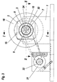
- Fig. 3
- eine Stirnansicht,
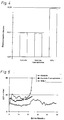
- Fig. 4
- ein Säulendiagramm der Überlebenszeiten dreier Versuchstiere,
- Fig. 5
- ein zugehöriges Diagramm über den intracraniellen Druckverlauf der Versuchstiere, und
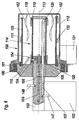
- Fig. 6
- eine zweite Ausführung eines bioartifiziellen Gerätes mit Leberfunktion in einem Axialschnitt gemäß Fig. 1.
- Fig. 1
- 3 shows an axial section through a first embodiment of a bioartificial device with liver function according to line II of FIG. 3,
- Fig. 2
- an axial section offset by 90 ° through the bioartificial device along the line II-II of Fig. 3,
- Fig. 3
- a front view,
- Fig. 4
- a bar chart of the survival times of three test animals,
- Fig. 5
- an associated diagram of the intracranial pressure curve of the test animals, and
- Fig. 6
- a second embodiment of a bioartificial device with liver function in an axial section according to FIG. 1.
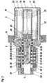
Gemäß Fig. 1 bis 3 weist ein bioartifizielles Gerät ein Reaktorgefäß 6 auf, das um eine
horizontale Achse 13 drehbar in einem Grundgestell 1 angeordnet ist. In das Grundgestell
1 ist ein Lagerblock 2 vertikal eingeschoben, in dem eine hohlzylindrische äußere
Antriebswelle 4 gelagert ist, die einen endseitigen Flansch 5 aufweist. Der Flansch 5
und ein mit diesem über einen leicht lösbaren Verschlußring 16 verbundener Gehäusetopf
11 aus insbesondere durchsichtigem Material bilden das Reaktorgefäß 6. In der
hohlzylindrischen Antriebswelle 4 ist eine zentrale Antriebswelle 3 drehbar gelagert. 1 to 3, a bioartificial device has a
Beide Antriebswellen 3, 4 sind mit Antriebsübertragungselementen 33, 34, beispielsweise
Zahnrädern, Riemenscheiben od. dgl. versehen, die über ein entsprechendes
Zugmittel mit einem Abtriebselement 32 eines Motors 31 verbunden sind. Das Antriebsübertragungselement
34 weist bevorzugt einen größeren Außendurchmesser auf,
sodaß die Drehzahl der Antriebswelle 4 kleiner als die Drehzahl der Antriebswelle 3 ist.Both drive
Das Reaktorgefäß 6 weist eine Zellkulturkammer 14 auf, die über mindestens eine im
Flansch 5 ausgebildete Prüföffnung 15 zugänglich ist. Über diese kann eine Probeentnahme
der Zellkultur ebenso erfolgen wie eine Entnahme bzw. Zufuhr, um eventuelle
Druckänderungen im Reaktorgefäß 6 auszugleichen. Von der bzw. einer Prüföffnung
15 erstreckt sich vorzugsweise ein Rohr- oder Schlauchstück 54 ins Innere der Zellkulturkammer
14, um eine Probenentnahme aus einem nicht randständigen Bereich zu
ermöglichen.The
Durch die Zellkulturkammer 14 führt eine Durchflußkammer 17 für ein Nährmedium
und eine Durchflußkammer 21 für Plasma bzw. Blut. Die Durchflußkammem 17 und 21
sind voneinander getrennt angeordnet und jeweils durch einen Schlauch 18, 22 gebildet,
der aus einem semipermeablen Material, insbesondere einem Polyvinylidendifluorid
(PVDF) besteht, dessen Porengröße maximal etwa 100.000 Dalton entspricht.
Die Durchflußkammer 17 für das Nährmedium ist durch den Schlauch 18 gebildet, der
auf einem Träger 19 schraubenförmig gewickelt ist, der mehrere die Windungen aufnehmende
Trägerleisten aufweist. Der Träger 19 steht stirnseitig von einem Verbindungselement
20 ab, das an der zentralen Antriebswelle 3 befestigt ist. Der Träger 19
und der Schlauch 18 drehen sich daher mit der Antriebswelle 3 mit. Der Schlauch 22,
der die Durchflußkammer 21 für Plasma bzw. Blut bildet, ist ebenfalls auf zwei bis acht
Trägerleisten schraubenförmig aufgewickelt, die den Träger 23 bilden. Die Trägerleisten
des Trägers 23 stehen nahe der Umfangswand 12 des Reaktorgefäßes 6 vom
Flansch 5 ab, der an der bevorzugt langsamer drehenden äußeren Antriebswelle 4
vorgesehen ist.A flow chamber 17 for a nutrient medium leads through the
Beide Schläuche 18, 22 tauchen in die Zellkulturkammer 14 ein, wobei durch die horizontale
Drehachse 13 und den bevorzugten Drehzahlunterschied zwischen den beiden
Schlauchwendeln ein geringfügig schonender Rühreffekt in der Zellkultur gegeben ist,
durch den der Stoffaustausch zwischen dem Nährmedium im zentralen Schlauch 18
und der Zellkultur sowie zwischen dem Plasma bzw. Blut im äußeren Schlauch 22 und
der Zellkultur begünstigt wird. Die schraubenförmige Anordnung der beiden Schläuche
ergibt weiters eine sehr große Austauschfläche zwischen den einzelnen Medien. Die
Schlauchwindungen können einander berührend (Fig. 1) oder mit Abstand (Fig. 2) auf
den Trägern 19, 23 angeordnet sein. Eine berührende Anordnung ergibt aufgrund einer
höheren Anzahl von Windungen eine größere Gesamtlänge, während eine beabstandete
Anordnung den Austausch auf dem gesamten Umfang des Schlauches ermöglicht,
da die gegenseitige Abdeckung im Berührungsbereich der Windungen entfällt.Both
Der Zufluß des Nährmediums und des Plasmas bzw. Blutes in die Schläuche 18, 22
und deren Rückfluß erfolgen jeweils über die zentrale Antriebswelle 3 in voneinander
getrennten Strömungskanälen. Am Lagerblock 2 sind Anschlüsse 47, 48, 49, 50 vorgesehen,
die mit radialen Bohrungen 27, 28, 29, 30 der zentralen Antriebswelle 3 in
Strömungsverbindung stehen. Zwischen der Innenwand des Lagerblocks 2 und der
äußeren Antriebswelle 4 sind pro Zufluß bzw. Rückfluß äußere Ringkanäle 41 vorgesehen,
die durch axial beabstandete Trennringe 42 begrenzt sind und die jeweils Strömungsverbindungen
zwischen den Anschlüssen 47, 48, 49, 50 und radialen Bohrungen
37, 38, 39, 40 der sich drehenden äußeren Antriebswelle 4 herstellen. Zwischen
der Innenwand der äußeren Antriebswelle 4 und der zentralen Antriebswelle 3 sind pro
Zufluß bzw. Rückfluß innere Ringkanäle 35 vorgesehen, die durch axial beabstandete
Trennringe 36 begrenzt sind und die jeweilige Strömungsverbindung zwischen den
radialen Bohrungen 37, 38, 39, 40 der äußeren Antriebswelle 4 und den Bohrungen 27,
28, 29, 30 der sich schneller drehenden zentralen Antriebswelle 3 herstellen.The inflow of the nutrient medium and the plasma or blood into the
Die zentrale Antriebswelle 3 enthält vier zueinander parallele Strömungskanäle 7, 8, 9,
10. Von diesen ist der Strömungskanal 7 durch ein in den Gehäusetopf 11 ragendes
Verlängerungsrohr 25 verlängert, dessen radial abgebogenes Ende mit dem dem
Flansch 5 gegenüberliegenden, ersten Ende des Schlauches 18 verbunden ist. Der
Strömungskanal 8 ist in ein Verbindungselement 20 verlängert, und endet in einer radialen
Eintrittsbohrung 24, an die das flanschnahe zweite Ende des Schlauchs 18 angeschlossen
ist. Nährmedium zur Versorgung der Zellkultur fließt somit über den
ersten Anschluß 47 in den äußeren Ringkanal 41, durch die Bohrung 37 der äußeren
Antriebswelle 4 in den inneren Ringkanal 35, durch die Bohrung 27 der zentralen Antriebswelle
3 in deren ersten Strömungskanal 7 und durch das Verlängerungsrohr 25 in
den Schlauch 18. Aus dem Schlauch 18 fließt das zirkulierende Nährmedium durch die
Eintrittsöffnung 24, den zweiten Strömungskanal 8 und die radiale Bohrung 28 der
zentralen Antriebswelle 3 in den zugehörigen inneren Ringkanal 35, durch die Bohrung
38 der äußeren Antriebswelle 4 und den zugehörigen äußeren Ringkanal 41 zum
zweiten Anschluß 48 des Lagerblocks 2.The
Die Strömungskanäle 9, 10 der zentralen Antriebswelle 3 sind über innere radiale Bohrungen
43, 44 mit Ringkanälen 45 verbunden, die durch Trennringe 46 begrenzt und
zwischen der zentralen Antriebwelle 3 und dem Flansch 5 der äußeren Antriebswelle 4
angeordnet sind. Der Flansch 5 weist Kanäle 51, 52 auf, die in den Bereich des äußeren
Trägers 23 führen. Am Ausgang des Kanales 51 ist der Schlauch 22 angeschlossen.
Vom Ausgang des Kanales 52 führt ein Verlängerungsrohr 53 zum freien Ende
des Trägers 23, an dem das zweite Ende des Schlauches 22 mit dem Verlängerungsrohr
53 verbunden ist.The
Plasma bzw. Blut strömt über den dritten Anschluß 49 in das bioartifizielle Gerät ein
und gelangt durch den zugehörigen äußeren Ringkanal 41 und die Bohrung 39 der
äußeren Antriebswelle 4 in den zugehörigen inneren Ringkanal 35, durch die Bohrung
29 der zentralen Antriebswelle 3 in deren dritten Strömungskanal 9, durch die zweite,
innere Bohrung 43 am Ende des Strömungskanals 9 in den zugehörigen Ringkanal 45
und durch den Kanal 51 im Flansch 5 zur äußeren Schlauchwendel 22, in der durch
Stoffaustausch mit der Zellkultur in der Zellkulturkammer 14 eine Reinigung des Plasmas
bzw. Blutes erfolgt. Das behandelte Plasma bzw. Blut fließt durch das Verlängerungsrohr
53 und den Kanal 52 im Flansch 5 in den zugehörigen Ringkanal 45, durch
die innere Bohrung 44 der zentralen Antriebswelle 3 in deren vierten Strömungskanal
10, durch die äußere Bohrung 30 der zentralen Antriebswelle 3 in den zugehörigen
inneren Ringkanal 35, und durch die Bohrung 40 der äußeren Antriebswelle 4 und den
zugehörigen Ringkanal 41 zum vierten Anschluß 50 des Lagerblockes 2.Plasma or blood flows into the bioartificial device via the
Für die Erstbefüllung bzw. Entleerung wird der Lagerblock 2 aus dem Grundgestell 1
entnommen, sodaß das Reaktorgefäß 6 aufgestellt werden kann, wobei die Achse 13
lotrecht verläuft. Nach Abnahme des Verschlußringes 16 kann der Lagerblock 2 mit
dem Flansch 5 und den auf den beiden Trägern 19, 23 angeordneten Schlauchwendeln
18, 22 nach oben abgenommen werden. Die verbrauchte Zellkultur kann entleert
bzw. neue Zellkultur in den Gehäusetopf 11 eingefüllt werden. Die Einheit aus
Flansch 5 samit den beiden Schlauchwendeln 18, 22 und dem Lagerblock 2 wird auf
den Gehäusetopf 11 aufgesetzt und mit Hilfe des Verschlußringes 16 zum Reaktorgefäß
6 dichtend verschlossen. Anschließend kann das Reaktorgefäß 6 umgelegt und
mit Hilfe des Lagerblockes 2 liegend in das Grundgestell 1 eingesteckt werden.For the first filling or emptying, the
In bevorzugter Ausführung hat der Gehäusetopf 11 einen Rauminhalt von etwa einem
Kubikdezimeter und kann ca. 2 x 10¹⁰ in einem Medium suspendierte Hepatozyten aufnehmen.
Die Drehzahlen der beiden Antriebszellen 3, 4 liegen insbesondere zwischen
20 und 40 Umdrehungen pro Minute, wobei die Drehzahl der zentralen Antriebswelle 3
beispielsweise dem Eineinviertelfachen der Drehzahl der äußeren Antriebswelle 4 entspricht.
In diesem Fall liegen somit die Drehzahlen von 20 und 30 Umdrehungen bis 25
und 37,5 Umdrehungen pro Minute.In a preferred embodiment, the
Die Fig. 4 und 5 zeigen das Ergebnis eines Tierversuches, in dem bei drei deutschen Landschweinen mit je etwa 30 kg Lebendgewicht die Überlebensdauer in einem chirurgisch herbeigeführten Modell des akuten Leberversagens ermittelt wurde. Das akute Leberversagen wurde durch eine 80%-Leberresektion mit anschließender einstündiger Abklemmung des Hilus der Restleber herbeigeführt. Weiters wurde unter anderem der intracranielle Druck (ICP) kontrolliert. Da eine Plasmapherese auch zur Therapie bei akuter Leberinsuffizienz eingesetzt wird, wurde folgende Vorgabe getroffen: Eines der drei Tiere blieb ohne Therapie (Kontrolle), bei einem zweiten Tier wurde aus dem Blut in einem Plasmapheresegerät Plasma abgetrennt und als Vollblut ohne weitere Manipulation wieder reinfundiert (Kontrolle Plasmapherese). Beim dritten Tier wurde ebenfalls aus dem Blut in einem Plasmapheresegerät Plasma abgetrennt, und dieses dann durch ein bioartifizielles Gerät mit den oben beschriebenen Angaben hindurchgeführt. Das behandelte Plasma wurde wiederum mit dem zuvor abgetrennten Restblut vermischt und zurückgeführt (IBAL 1).4 and 5 show the result of an animal experiment in which three Germans Country pigs, each with about 30 kg live weight, the survival in one surgically induced model of acute liver failure. The Acute liver failure was caused by an 80% liver resection followed by an hour Clamping off the hilum of the residual liver. Furthermore, under controls intracranial pressure (ICP). Because plasmapheresis is also used for Therapy for acute liver failure is used, the following requirements have been made: One of the three animals remained without therapy (control), with a second animal plasma separated from the blood in a plasmapheresis device and as whole blood without further manipulation reinfused (control plasmapheresis). The third animal was also separated from the blood in a plasmapheresis device, and this is then passed through a bioartificial device with the information described above. The treated plasma was again separated with that previously Remnant blood mixed and returned (IBAL 1).
Fig. 4 zeigt, daß das Kontrolltier und das Plasmapherese-Kontrolltier eine Überlebenszeit von jeweils nahezu 24 Stunden aufwiesen. Hingegen lebte das dritte Tier, dessen Plasma im erfindungsgemäßen bioartifiziellen Gerät gereinigt bzw. regeneriert wurde, nahezu 50 Stunden, wobei die Todesursache, wie Fig. 5 zeigt, nicht in einem Anstieg des intracraniellen Drucks (ICP) gelegen hat. Hingegen stieg der intracranielle Druck beim Kontrolltier extrem, und beim Plasmapherese-Kontrolltier zwar vermindert, aber doch deutlich. Fig. 4 shows that the control animal and the plasmapheresis control animal have a survival time of almost 24 hours each. The third animal, on the other hand, lived Plasma was cleaned or regenerated in the bioartificial device according to the invention, nearly 50 hours, with the cause of death, as shown in Fig. 5, not increasing intracranial pressure (ICP). In contrast, the intracranial pressure increased extreme in the control animal and reduced in the plasmapheresis control animal, but clearly.
In der Ausführung nach Fig. 6 ist in einen Lagerblock 102 ein zentrales zylindrisches
Halteelement 103 abnehmbar angeordnet. Das Halteelement weist die gezeigten Anschlüsse
147, 148, über die Nährmedium zu- und abgeführt werden kann, sowie zwei
weitere Anschlüsse auf, über die Blut und Plasma zu- und abgeführt werden kann. Die
Anschlüsse 147, 148 münden in Strömungskanäle 107, 108, die sich parallel zur Achse
113 erstrecken. Auf dem Halteelement 103 ist ein Flansch 105 mit einem umfänglichen
Wälzlager 160 montiert, auf dem ein Gehäusetopf 111 eines Reaktorgefäßes 106
drehbar gelagert ist. Der Gehäusetopf 111 ist an der Außenseite der Wandung 112 mit
einem Zahnkranz 161 versehen, und über ein Antriebsübertragungselement mit einem
Motor 131 drehbar verbunden. Der Flansch 105 und der Gehäusetopf 111 des Reaktorgefäßes
106 beinhalten eine Zellkulturkammer 114, in die vom Boden des Gehäusetopfes
111 zwei Rührelemente 162 ragen, die die durch die Rotation der Gehäusewandung
112 bedingte, schonende Durchmischung des Inhalts der Zellkulturkammer
114 unterstützen.6, a central cylindrical is in a
Der Strömungskanal 108 endet in einem Verbindungselement 120, das eine radiale
Bohrung 124 aufweist. Der Strömungskanal 107 ist jenseits des Verbindungselementes
120 durch ein Verlängerungsrohr 125 weitergeführt. Ein auf Leisten eines Trägers 119
schraubenförmig gewickelter Schlauch 118 ist einerseits an das Verlängerungsrohr
125 und andererseits an die radiale Bohrung 124 angeschlossen, wobei die
Schlauchwendel zentral in Verlängerung des Halteelementes 103 in den rotierenden
Gehäusetopf 111 ragt.The
Als Durchflußkammer für Blut und Plasma dient ein zweiter auf Leisten eines Trägers
123 schraubenförmig gewickelter Schlauch 122, der über nicht gezeigte im Flansch
105 verlaufende Kanäle mit Strömungskanälen im Halteelement 103 verbunden ist,
von denen der Strömungskanal 109 strichliert angedeutet ist. Das Reaktorgefäß 106
weist eine Prüföffnung 115 auf, die über ein inneres Schlauch- oder Rohrstück 154 mit
der Zellkulturkammer 114 in Verbindung ist.A second on the slats of a carrier serves as the flow chamber for blood and
Claims (13)
Priority Applications (5)
| Application Number | Priority Date | Filing Date | Title |
|---|---|---|---|
| EP01103420A EP1234553A1 (en) | 2001-02-14 | 2001-02-14 | Bioartificial device |
| EP02710668A EP1363557A1 (en) | 2001-02-14 | 2002-02-11 | Bioartificial device for storing, cultivating and/or reproducing cells |
| JP2002563863A JP2004526438A (en) | 2001-02-14 | 2002-02-11 | Artificial bio device for cell storage, culture and / or propagation |
| PCT/AT2002/000045 WO2002064063A1 (en) | 2001-02-14 | 2002-02-11 | Bioartificial device for storing, cultivating and/or reproducing cells |
| US10/641,275 US7067307B2 (en) | 2001-02-14 | 2003-08-14 | Bioartificial device for the storage, cultivation and/or multiplication of cells |
Applications Claiming Priority (1)
| Application Number | Priority Date | Filing Date | Title |
|---|---|---|---|
| EP01103420A EP1234553A1 (en) | 2001-02-14 | 2001-02-14 | Bioartificial device |
Publications (1)
| Publication Number | Publication Date |
|---|---|
| EP1234553A1 true EP1234553A1 (en) | 2002-08-28 |
Family
ID=8176483
Family Applications (2)
| Application Number | Title | Priority Date | Filing Date |
|---|---|---|---|
| EP01103420A Withdrawn EP1234553A1 (en) | 2001-02-14 | 2001-02-14 | Bioartificial device |
| EP02710668A Withdrawn EP1363557A1 (en) | 2001-02-14 | 2002-02-11 | Bioartificial device for storing, cultivating and/or reproducing cells |
Family Applications After (1)
| Application Number | Title | Priority Date | Filing Date |
|---|---|---|---|
| EP02710668A Withdrawn EP1363557A1 (en) | 2001-02-14 | 2002-02-11 | Bioartificial device for storing, cultivating and/or reproducing cells |
Country Status (4)
| Country | Link |
|---|---|
| US (1) | US7067307B2 (en) |
| EP (2) | EP1234553A1 (en) |
| JP (1) | JP2004526438A (en) |
| WO (1) | WO2002064063A1 (en) |
Families Citing this family (16)
| Publication number | Priority date | Publication date | Assignee | Title |
|---|---|---|---|---|
| US7914612B2 (en) * | 2005-05-20 | 2011-03-29 | University Of Dayton | Compliant column sheath assembly for gas chromatography |
| GB2467645B (en) * | 2007-07-06 | 2011-12-21 | Univ London | A method of proliferating human hepatocyte cells |
| EP2640461B1 (en) | 2010-11-16 | 2019-06-19 | The Board Of Trustees Of The Leland Stanford Junior University | Systems for treatment of dry eye |
| US9821159B2 (en) | 2010-11-16 | 2017-11-21 | The Board Of Trustees Of The Leland Stanford Junior University | Stimulation devices and methods |
| US9265956B2 (en) | 2013-03-08 | 2016-02-23 | Oculeve, Inc. | Devices and methods for treating dry eye in animals |
| US9717627B2 (en) | 2013-03-12 | 2017-08-01 | Oculeve, Inc. | Implant delivery devices, systems, and methods |
| CN105307718B (en) | 2013-04-19 | 2018-05-11 | 奥库利维公司 | Nose stimulating apparatus and method |
| EP3689338A1 (en) | 2014-02-25 | 2020-08-05 | Oculeve, Inc. | Polymer formulations for nasolacrimal stimulation |
| DK3171928T3 (en) | 2014-07-25 | 2020-05-18 | Oculeve Inc | STIMULATION PATTERNS FOR TREATMENT OF DRY EYES |
| WO2016065213A1 (en) | 2014-10-22 | 2016-04-28 | Oculeve, Inc. | Implantable nasal stimulator systems and methods |
| AU2015335776B2 (en) | 2014-10-22 | 2020-09-03 | Oculeve, Inc. | Stimulation devices and methods for treating dry eye |
| US9764150B2 (en) | 2014-10-22 | 2017-09-19 | Oculeve, Inc. | Contact lens for increasing tear production |
| US10426958B2 (en) | 2015-12-04 | 2019-10-01 | Oculeve, Inc. | Intranasal stimulation for enhanced release of ocular mucins and other tear proteins |
| US10252048B2 (en) | 2016-02-19 | 2019-04-09 | Oculeve, Inc. | Nasal stimulation for rhinitis, nasal congestion, and ocular allergies |
| CA3022683A1 (en) | 2016-05-02 | 2017-11-09 | Oculeve, Inc. | Intranasal stimulation for treatment of meibomian gland disease and blepharitis |
| JP2020500609A (en) | 2016-12-02 | 2020-01-16 | オキュリーブ, インコーポレイテッド | Apparatus and method for dry eye prediction and treatment recommendations |
Citations (5)
| Publication number | Priority date | Publication date | Assignee | Title |
|---|---|---|---|---|
| US4242460A (en) * | 1978-12-26 | 1980-12-30 | Chick William L | Cell culture device |
| US4242459A (en) * | 1978-11-02 | 1980-12-30 | Chick William L | Cell culture device |
| US4323457A (en) * | 1977-03-21 | 1982-04-06 | Connaught Laboratories Limited | Artificial endocrine pancreas |
| US4649114A (en) * | 1979-10-05 | 1987-03-10 | Intermedicat Gmbh | Oxygen permeable membrane in fermenter for oxygen enrichment of broth |
| US5043260A (en) * | 1987-11-02 | 1991-08-27 | Rhode Island Hospital | Perfusion device with hepatocytes |
Family Cites Families (9)
| Publication number | Priority date | Publication date | Assignee | Title |
|---|---|---|---|---|
| US3734851A (en) * | 1969-12-29 | 1973-05-22 | K Matsumura | Method and device for purifying blood |
| US4808378A (en) * | 1985-11-11 | 1989-02-28 | Senko Medical Instrument Mfg. Co., Ltd. | Blood oxygenator |
| US5081035A (en) * | 1988-04-18 | 1992-01-14 | The University Of Michigan | Bioreactor system |
| US5605835A (en) | 1988-05-23 | 1997-02-25 | Regents Of The University Of Minnesota | Bioreactor device with application as a bioartificial liver |
| US4988623A (en) * | 1988-06-30 | 1991-01-29 | The United States Of America As Represented By The Administrator Of The National Aeronautics And Space Administration | Rotating bio-reactor cell culture apparatus |
| US5026650A (en) * | 1988-06-30 | 1991-06-25 | The United States Of Amercia As Represented By The Administrator Of The National Aeronautics And Space Administration | Horizontally rotated cell culture system with a coaxial tubular oxygenator |
| FR2640638B1 (en) * | 1988-12-20 | 1991-02-15 | Commissariat Energie Atomique | BIOREACTOR AND DEVICE FOR THE CULTURE OF ANIMAL CELLS |
| US5712154A (en) * | 1995-06-07 | 1998-01-27 | W.R. Grace & Co.-Conn. | Dual fiber bioreactor |
| US5827729A (en) | 1996-04-23 | 1998-10-27 | Advanced Tissue Sciences | Diffusion gradient bioreactor and extracorporeal liver device using a three-dimensional liver tissue |
-
2001
- 2001-02-14 EP EP01103420A patent/EP1234553A1/en not_active Withdrawn
-
2002
- 2002-02-11 EP EP02710668A patent/EP1363557A1/en not_active Withdrawn
- 2002-02-11 JP JP2002563863A patent/JP2004526438A/en active Pending
- 2002-02-11 WO PCT/AT2002/000045 patent/WO2002064063A1/en active Application Filing
-
2003
- 2003-08-14 US US10/641,275 patent/US7067307B2/en not_active Expired - Fee Related
Patent Citations (5)
| Publication number | Priority date | Publication date | Assignee | Title |
|---|---|---|---|---|
| US4323457A (en) * | 1977-03-21 | 1982-04-06 | Connaught Laboratories Limited | Artificial endocrine pancreas |
| US4242459A (en) * | 1978-11-02 | 1980-12-30 | Chick William L | Cell culture device |
| US4242460A (en) * | 1978-12-26 | 1980-12-30 | Chick William L | Cell culture device |
| US4649114A (en) * | 1979-10-05 | 1987-03-10 | Intermedicat Gmbh | Oxygen permeable membrane in fermenter for oxygen enrichment of broth |
| US5043260A (en) * | 1987-11-02 | 1991-08-27 | Rhode Island Hospital | Perfusion device with hepatocytes |
Non-Patent Citations (1)
| Title |
|---|
| "CONTROLLED-TURBULENCE BIOREACTORS", NTIS TECH NOTES,US,US DEPARTMENT OF COMMERCE. SPRINGFIELD, VA, 1 March 1990 (1990-03-01), pages 294, XP000127294, ISSN: 0889-8464 * |
Also Published As
| Publication number | Publication date |
|---|---|
| EP1363557A1 (en) | 2003-11-26 |
| US7067307B2 (en) | 2006-06-27 |
| US20040033593A1 (en) | 2004-02-19 |
| JP2004526438A (en) | 2004-09-02 |
| WO2002064063A1 (en) | 2002-08-22 |
Similar Documents
| Publication | Publication Date | Title |
|---|---|---|
| EP1234553A1 (en) | Bioartificial device | |
| DE2734248A1 (en) | PORTABLE ARTIFICIAL KIDNEY | |
| DE60030885T2 (en) | FILTER CARTRIDGE FOR STERILE LIQUID AND METHOD FOR THE USE THEREOF | |
| DE2715821C2 (en) | Method for in vitro cell culture and cell culture reaction vessel for carrying out this method | |
| DE3035118C2 (en) | Method for the cultivation of swimming animal cells and device for carrying out the method | |
| DE4206585C2 (en) | Device for mass culture of cells | |
| DE3634763C2 (en) | ||
| DE2624373C2 (en) | Process for the production of sterile filtered cryoprecipitate with an enrichment of factor VIII | |
| DE2711995A1 (en) | DISCONNECTING DEVICE, IN PARTICULAR DEVICE FOR HAEMODIALYSIS | |
| DE1279291B (en) | Device for performing blood exchange processes | |
| DE2640451A1 (en) | METHOD AND DEVICE FOR THE CULTIVATION, MAINTENANCE AND TRANSPORTATION OF LIVING ORGANISMS | |
| CH624712A5 (en) | ||
| DE2430171A1 (en) | DIALYZING DEVICE WITH SELECTIVE CHEMICAL ACTIVITY | |
| DE2333574C2 (en) | Method for removing gas from an ethylene oxide sterilizer | |
| DE60220790T2 (en) | Device for changing a liquid by means of a selectively permeable membrane | |
| WO2000059618A1 (en) | Method for populating substrates with biological cells and populating devices that can be used therefor | |
| DE1960505A1 (en) | Device for purifying blood | |
| DE2025420C3 (en) | Dialysis column | |
| DE3222244A1 (en) | METHOD AND DEVICE FOR TREATING HUMAN BLOOD | |
| DE19962314B4 (en) | Device for peritoneal dialysis | |
| DE7129627U (en) | DIALYZER, IN PARTICULAR ARTIFICIAL KIDNEY | |
| EP1756263A1 (en) | Liquid/gas phase exposure reactor for cell cultivation | |
| DE2701976A1 (en) | Counter-flow type blood washing centrifuge - uses compressible receptacle of centrally and rotationally symmetrical shape | |
| WO2006069737A1 (en) | Reactor and reactor unit with hollow fibers | |
| DE3541738A1 (en) | METHOD AND DEVICE FOR CULTIVATING CELLS |
Legal Events
| Date | Code | Title | Description |
|---|---|---|---|
| PUAI | Public reference made under article 153(3) epc to a published international application that has entered the european phase |
Free format text: ORIGINAL CODE: 0009012 |
|
| AK | Designated contracting states |
Kind code of ref document: A1 Designated state(s): AT BE CH CY DE DK ES FI FR GB GR IE IT LI LU MC NL PT SE TR |
|
| AX | Request for extension of the european patent |
Free format text: AL;LT;LV;MK;RO;SI |
|
| AKX | Designation fees paid | ||
| REG | Reference to a national code |
Ref country code: DE Ref legal event code: 8566 |
|
| STAA | Information on the status of an ep patent application or granted ep patent |
Free format text: STATUS: THE APPLICATION IS DEEMED TO BE WITHDRAWN |
|
| 18D | Application deemed to be withdrawn |
Effective date: 20030301 |