EP1237610B1 - Apparatus for co-application of gases and drugs - Google Patents
Apparatus for co-application of gases and drugs Download PDFInfo
- Publication number
- EP1237610B1 EP1237610B1 EP00992143A EP00992143A EP1237610B1 EP 1237610 B1 EP1237610 B1 EP 1237610B1 EP 00992143 A EP00992143 A EP 00992143A EP 00992143 A EP00992143 A EP 00992143A EP 1237610 B1 EP1237610 B1 EP 1237610B1
- Authority
- EP
- European Patent Office
- Prior art keywords
- drug
- needle
- chamber
- head
- cap
- Prior art date
- Legal status (The legal status is an assumption and is not a legal conclusion. Google has not performed a legal analysis and makes no representation as to the accuracy of the status listed.)
- Expired - Lifetime
Links
Images


Classifications
-
- A—HUMAN NECESSITIES
- A61—MEDICAL OR VETERINARY SCIENCE; HYGIENE
- A61M—DEVICES FOR INTRODUCING MEDIA INTO, OR ONTO, THE BODY; DEVICES FOR TRANSDUCING BODY MEDIA OR FOR TAKING MEDIA FROM THE BODY; DEVICES FOR PRODUCING OR ENDING SLEEP OR STUPOR
- A61M15/00—Inhalators
- A61M15/0001—Details of inhalators; Constructional features thereof
- A61M15/0003—Details of inhalators; Constructional features thereof with means for dispensing more than one drug
-
- A—HUMAN NECESSITIES
- A61—MEDICAL OR VETERINARY SCIENCE; HYGIENE
- A61K—PREPARATIONS FOR MEDICAL, DENTAL OR TOILETRY PURPOSES
- A61K47/00—Medicinal preparations characterised by the non-active ingredients used, e.g. carriers or inert additives; Targeting or modifying agents chemically bound to the active ingredient
- A61K47/02—Inorganic compounds
-
- A—HUMAN NECESSITIES
- A61—MEDICAL OR VETERINARY SCIENCE; HYGIENE
- A61H—PHYSICAL THERAPY APPARATUS, e.g. DEVICES FOR LOCATING OR STIMULATING REFLEX POINTS IN THE BODY; ARTIFICIAL RESPIRATION; MASSAGE; BATHING DEVICES FOR SPECIAL THERAPEUTIC OR HYGIENIC PURPOSES OR SPECIFIC PARTS OF THE BODY
- A61H33/00—Bathing devices for special therapeutic or hygienic purposes
- A61H33/14—Devices for gas baths with ozone, hydrogen, or the like
-
- A—HUMAN NECESSITIES
- A61—MEDICAL OR VETERINARY SCIENCE; HYGIENE
- A61K—PREPARATIONS FOR MEDICAL, DENTAL OR TOILETRY PURPOSES
- A61K31/00—Medicinal preparations containing organic active ingredients
- A61K31/13—Amines
- A61K31/135—Amines having aromatic rings, e.g. ketamine, nortriptyline
- A61K31/137—Arylalkylamines, e.g. amphetamine, epinephrine, salbutamol, ephedrine or methadone
-
- A—HUMAN NECESSITIES
- A61—MEDICAL OR VETERINARY SCIENCE; HYGIENE
- A61K—PREPARATIONS FOR MEDICAL, DENTAL OR TOILETRY PURPOSES
- A61K31/00—Medicinal preparations containing organic active ingredients
- A61K31/21—Esters, e.g. nitroglycerine, selenocyanates
-
- A—HUMAN NECESSITIES
- A61—MEDICAL OR VETERINARY SCIENCE; HYGIENE
- A61K—PREPARATIONS FOR MEDICAL, DENTAL OR TOILETRY PURPOSES
- A61K31/00—Medicinal preparations containing organic active ingredients
- A61K31/33—Heterocyclic compounds
- A61K31/395—Heterocyclic compounds having nitrogen as a ring hetero atom, e.g. guanethidine or rifamycins
- A61K31/41—Heterocyclic compounds having nitrogen as a ring hetero atom, e.g. guanethidine or rifamycins having five-membered rings with two or more ring hetero atoms, at least one of which being nitrogen, e.g. tetrazole
- A61K31/4164—1,3-Diazoles
- A61K31/4178—1,3-Diazoles not condensed 1,3-diazoles and containing further heterocyclic rings, e.g. pilocarpine, nitrofurantoin
-
- A—HUMAN NECESSITIES
- A61—MEDICAL OR VETERINARY SCIENCE; HYGIENE
- A61K—PREPARATIONS FOR MEDICAL, DENTAL OR TOILETRY PURPOSES
- A61K31/00—Medicinal preparations containing organic active ingredients
- A61K31/33—Heterocyclic compounds
- A61K31/395—Heterocyclic compounds having nitrogen as a ring hetero atom, e.g. guanethidine or rifamycins
- A61K31/435—Heterocyclic compounds having nitrogen as a ring hetero atom, e.g. guanethidine or rifamycins having six-membered rings with one nitrogen as the only ring hetero atom
- A61K31/46—8-Azabicyclo [3.2.1] octane; Derivatives thereof, e.g. atropine, cocaine
-
- A—HUMAN NECESSITIES
- A61—MEDICAL OR VETERINARY SCIENCE; HYGIENE
- A61K—PREPARATIONS FOR MEDICAL, DENTAL OR TOILETRY PURPOSES
- A61K31/00—Medicinal preparations containing organic active ingredients
- A61K31/33—Heterocyclic compounds
- A61K31/395—Heterocyclic compounds having nitrogen as a ring hetero atom, e.g. guanethidine or rifamycins
- A61K31/435—Heterocyclic compounds having nitrogen as a ring hetero atom, e.g. guanethidine or rifamycins having six-membered rings with one nitrogen as the only ring hetero atom
- A61K31/47—Quinolines; Isoquinolines
- A61K31/485—Morphinan derivatives, e.g. morphine, codeine
-
- A—HUMAN NECESSITIES
- A61—MEDICAL OR VETERINARY SCIENCE; HYGIENE
- A61K—PREPARATIONS FOR MEDICAL, DENTAL OR TOILETRY PURPOSES
- A61K38/00—Medicinal preparations containing peptides
- A61K38/04—Peptides having up to 20 amino acids in a fully defined sequence; Derivatives thereof
- A61K38/08—Peptides having 5 to 11 amino acids
- A61K38/085—Angiotensins
-
- A—HUMAN NECESSITIES
- A61—MEDICAL OR VETERINARY SCIENCE; HYGIENE
- A61M—DEVICES FOR INTRODUCING MEDIA INTO, OR ONTO, THE BODY; DEVICES FOR TRANSDUCING BODY MEDIA OR FOR TAKING MEDIA FROM THE BODY; DEVICES FOR PRODUCING OR ENDING SLEEP OR STUPOR
- A61M11/00—Sprayers or atomisers specially adapted for therapeutic purposes
- A61M11/06—Sprayers or atomisers specially adapted for therapeutic purposes of the injector type
-
- A—HUMAN NECESSITIES
- A61—MEDICAL OR VETERINARY SCIENCE; HYGIENE
- A61M—DEVICES FOR INTRODUCING MEDIA INTO, OR ONTO, THE BODY; DEVICES FOR TRANSDUCING BODY MEDIA OR FOR TAKING MEDIA FROM THE BODY; DEVICES FOR PRODUCING OR ENDING SLEEP OR STUPOR
- A61M13/00—Insufflators for therapeutic or disinfectant purposes, i.e. devices for blowing a gas, powder or vapour into the body
-
- A—HUMAN NECESSITIES
- A61—MEDICAL OR VETERINARY SCIENCE; HYGIENE
- A61M—DEVICES FOR INTRODUCING MEDIA INTO, OR ONTO, THE BODY; DEVICES FOR TRANSDUCING BODY MEDIA OR FOR TAKING MEDIA FROM THE BODY; DEVICES FOR PRODUCING OR ENDING SLEEP OR STUPOR
- A61M15/00—Inhalators
- A61M15/0028—Inhalators using prepacked dosages, one for each application, e.g. capsules to be perforated or broken-up
- A61M15/003—Inhalators using prepacked dosages, one for each application, e.g. capsules to be perforated or broken-up using capsules, e.g. to be perforated or broken-up
- A61M15/0033—Details of the piercing or cutting means
- A61M15/0041—Details of the piercing or cutting means with movable piercing or cutting means
-
- A—HUMAN NECESSITIES
- A61—MEDICAL OR VETERINARY SCIENCE; HYGIENE
- A61M—DEVICES FOR INTRODUCING MEDIA INTO, OR ONTO, THE BODY; DEVICES FOR TRANSDUCING BODY MEDIA OR FOR TAKING MEDIA FROM THE BODY; DEVICES FOR PRODUCING OR ENDING SLEEP OR STUPOR
- A61M15/00—Inhalators
- A61M15/0065—Inhalators with dosage or measuring devices
- A61M15/0068—Indicating or counting the number of dispensed doses or of remaining doses
- A61M15/0081—Locking means
-
- A—HUMAN NECESSITIES
- A61—MEDICAL OR VETERINARY SCIENCE; HYGIENE
- A61M—DEVICES FOR INTRODUCING MEDIA INTO, OR ONTO, THE BODY; DEVICES FOR TRANSDUCING BODY MEDIA OR FOR TAKING MEDIA FROM THE BODY; DEVICES FOR PRODUCING OR ENDING SLEEP OR STUPOR
- A61M15/00—Inhalators
- A61M15/009—Inhalators using medicine packages with incorporated spraying means, e.g. aerosol cans
-
- A—HUMAN NECESSITIES
- A61—MEDICAL OR VETERINARY SCIENCE; HYGIENE
- A61M—DEVICES FOR INTRODUCING MEDIA INTO, OR ONTO, THE BODY; DEVICES FOR TRANSDUCING BODY MEDIA OR FOR TAKING MEDIA FROM THE BODY; DEVICES FOR PRODUCING OR ENDING SLEEP OR STUPOR
- A61M37/00—Other apparatus for introducing media into the body; Percutany, i.e. introducing medicines into the body by diffusion through the skin
-
- A—HUMAN NECESSITIES
- A61—MEDICAL OR VETERINARY SCIENCE; HYGIENE
- A61P—SPECIFIC THERAPEUTIC ACTIVITY OF CHEMICAL COMPOUNDS OR MEDICINAL PREPARATIONS
- A61P9/00—Drugs for disorders of the cardiovascular system
- A61P9/04—Inotropic agents, i.e. stimulants of cardiac contraction; Drugs for heart failure
-
- A—HUMAN NECESSITIES
- A61—MEDICAL OR VETERINARY SCIENCE; HYGIENE
- A61P—SPECIFIC THERAPEUTIC ACTIVITY OF CHEMICAL COMPOUNDS OR MEDICINAL PREPARATIONS
- A61P9/00—Drugs for disorders of the cardiovascular system
- A61P9/12—Antihypertensives
-
- A—HUMAN NECESSITIES
- A61—MEDICAL OR VETERINARY SCIENCE; HYGIENE
- A61H—PHYSICAL THERAPY APPARATUS, e.g. DEVICES FOR LOCATING OR STIMULATING REFLEX POINTS IN THE BODY; ARTIFICIAL RESPIRATION; MASSAGE; BATHING DEVICES FOR SPECIAL THERAPEUTIC OR HYGIENIC PURPOSES OR SPECIFIC PARTS OF THE BODY
- A61H33/00—Bathing devices for special therapeutic or hygienic purposes
- A61H33/14—Devices for gas baths with ozone, hydrogen, or the like
- A61H2033/145—Devices for gas baths with ozone, hydrogen, or the like with CO2
-
- A—HUMAN NECESSITIES
- A61—MEDICAL OR VETERINARY SCIENCE; HYGIENE
- A61M—DEVICES FOR INTRODUCING MEDIA INTO, OR ONTO, THE BODY; DEVICES FOR TRANSDUCING BODY MEDIA OR FOR TAKING MEDIA FROM THE BODY; DEVICES FOR PRODUCING OR ENDING SLEEP OR STUPOR
- A61M15/00—Inhalators
- A61M15/0065—Inhalators with dosage or measuring devices
-
- A—HUMAN NECESSITIES
- A61—MEDICAL OR VETERINARY SCIENCE; HYGIENE
- A61M—DEVICES FOR INTRODUCING MEDIA INTO, OR ONTO, THE BODY; DEVICES FOR TRANSDUCING BODY MEDIA OR FOR TAKING MEDIA FROM THE BODY; DEVICES FOR PRODUCING OR ENDING SLEEP OR STUPOR
- A61M15/00—Inhalators
- A61M15/08—Inhaling devices inserted into the nose
-
- A—HUMAN NECESSITIES
- A61—MEDICAL OR VETERINARY SCIENCE; HYGIENE
- A61M—DEVICES FOR INTRODUCING MEDIA INTO, OR ONTO, THE BODY; DEVICES FOR TRANSDUCING BODY MEDIA OR FOR TAKING MEDIA FROM THE BODY; DEVICES FOR PRODUCING OR ENDING SLEEP OR STUPOR
- A61M2202/00—Special media to be introduced, removed or treated
- A61M2202/02—Gases
- A61M2202/0225—Carbon oxides, e.g. Carbon dioxide
-
- A—HUMAN NECESSITIES
- A61—MEDICAL OR VETERINARY SCIENCE; HYGIENE
- A61M—DEVICES FOR INTRODUCING MEDIA INTO, OR ONTO, THE BODY; DEVICES FOR TRANSDUCING BODY MEDIA OR FOR TAKING MEDIA FROM THE BODY; DEVICES FOR PRODUCING OR ENDING SLEEP OR STUPOR
- A61M2202/00—Special media to be introduced, removed or treated
- A61M2202/06—Solids
- A61M2202/064—Powder
Abstract
Description
- This invention relates to gas dispensers for delivering carbon dioxide (CO2), or other gas to individuals. Similar devices are described in U.S. Pat. Application No. 09/614,389 filed July 12, 2000, whose subject matter is published as WO 01/03645. That application describes use of CO2, or other therapeutic gas or agents, and associated transmucosal dispensing apparatus for providing controlled amounts of gas to the nose, mouth and/or eye for use in the relief of headaches, allergic rhinitis, and asthma, among other ailments. The present invention, however, includes transmucosal or inhalational dispensing apparatus for co-application of selected drugs with gas and/or vapor to potentiate (i.e., beneficially improve) the action of the drug or of the gas or vapor.
- One possible physiological basis for the invention is as follows:
- Drugs act upon blood vessels (vasoactive drugs), muscles (myoactive drugs), and/or nerves (neuroactive drugs) to produce their beneficial effects. It is well established that vasoactive drugs (causing vasodilation or vasoconstriction) may be used to relieve allergic rhinitis (e.g., vasoconstrictor decongestants) as well as migraine and other forms of headache (e.g., vasoconstrictors). Similarly, myoactive drugs that cause bronchial smooth muscle relaxation result in bronchodilation and increased ventilation. It is also well established that myoactive drugs (causing muscle contraction or muscle relaxation) and neuroactive drugs (causing neural excitation or neural inhibition) may be used to relieve asthma (sympathomimetic bronchodilators).
- Like drugs, certain gases and vapors are physiologically active substances. The gases carbon dioxide and nitric oxide are known to be vasoactive, myoactive, and neuroactive [1]. Oxygen, nitrous oxide, helium, and dilute mixtures of nitric oxide may also be vasoactive, myoactive, and/or neuroactive. In addition, vapors from certain substances that lower the pH of mucosa to a degree similar to that of carbon dioxide, such as hydrochloric acid (HCl), nitric acid (HNO3), and hydrofluoric acid (HF) (all usually diluted with air) can be effective [6], and thus, in general, isocapnic mixtures of acid gases may be effective as well. Therefore, as used herein, "gas" and "gaseous" may refer to any physiologically active gas or vapor.
- If a drug is co-applied to a particular tissue or organ with CO2 NO, or other vasoactive, myoactive, or neuroactive gas or vapor as taught and claimed herein, the speed and efficacy of the drug action in such tissue or organ may be controlled. As a specific example for CO2, in an in vivo test, the ability of the drug atropine to inhibit serotonin-induced bronchial smooth muscle contraction was found to be potentiated from 46% inhibition to 62% inhibition by co-application of a 10% CO2 concentration [2]. Similarly, the inhibitory effect of the drug hexamethonium was potentiated from 37% inhibition to 67% inhibition by co-application of a 10% CO2 [2].
- The co-application of a drug with a gas or vapor can be performed in at least three different ways: First, the drug and gas can be applied together locally by co-infusion and transmucosal co-absorption nasally, orally, and/or via the eye or ear. The form of the drug, of course, would need to be suitable for such infusion, for example, a fine powder or liquid. If the combination of the drug and gas is applied nasally or orally for local transmucosal absorption, the individual would substantially inhibit passage of the drug and gas into his lungs and trachea by limiting inhalation of the gas and drug. Second, the drug and gas may be applied separately. The drug may be applied by any conventional means such as inhalation, pills, capsules, hypodermic injection or epidermal patches, and the individual may infuse a nostril or nostrils, mouth, eye or ear with the gas before, during or after application of the drug. As a variation of this method of co-application, the gas may instead be inhaled. Third, a combination of the drug and gas may be inhaled.
- As an example of the first method, a drug presently infused into the respiratory passages, mouth, eyes, or ears by entraining with air, e.g., as an aerosol, powder, or spray, can be applied instead by entraining with CO2, e.g., through aspiration of a drug-containing liquid or powder by CO2. In particular, the action of drugs developed and presently used for relieving respiratory and headache symptoms may be improved by their co-infusion with CO2 or NO. The vasodilation induced by CO2 or NO improves the speed and extent of absorption and distribution of the drug in the tissue in which it is co-absorbed with CO2 or NO. This is beneficial through more rapid relief being obtained, and through reduction in the quantity of drug required to obtain the relief. Reduction in the required quantity of drug reduces the cost of treatment per dose and particularly reduces the side effects of such drugs, which are severe restrictions to their present use.
- With respect to the second method, a particular benefit of co-application of such drugs with CO2 is that, in addition to the reduction of the total amount of drug required, the effect of the drug can be controlled or "modulated" in the course of its action after application. Inhalation or infusion of CO2 prior to drug application can increase the effectiveness and reduce the required quantity of the drug. Alternatively, inhalation or infusion of CO2 after application of a drug can enhance the effect of the drug at a controlled rate; i.e., if a more rapid or more intense effect of the drug is desired, CO2 can be inhaled or infused at the rate required to obtain the desired degree of enhancement. A particular advantage of such control is that the drug enhancement effect can be abruptly terminated, by ceasing CO2 inhalation or infusion, at the optimum level of beneficial drug effect that minimizes side or overdose effects. Also, since CO2 is rapidly eliminated from the body via the bloodstream and respiration, the enhancement is reversible after CO2 application is ceased, allowing continuous chronic adjustment of the drug effect.
- An example of the beneficial regulation of the effect of a powerful drug by CO2 inhalation or infusion is the co-application of CO2 and nitroglycerin for the relief of acute angina and during onset of a heart attack (myocardial infarction). Nitroglycerin is a powerful vasodilator. Ordinarily persons suffering from angina or from symptoms of heart attack place a nitroglycerin tablet under their tongue (transmucosal delivery). If this is not adequate to relieve the symptoms within three minutes, another tablet is similarly ingested. After another three minutes, if relief is not obtained, this process is again repeated. If the symptoms then persist, a person should be taken immediately to a hospital for emergency treatment. Some persons are extremely sensitive to the side effects of nitroglycerin however, including severe blood pressure reduction that can result in dizziness and fainting, especially after ingesting the second tablet, at a time when good judgment and deliberate corrective action are required. A few minutes of delay can be crucial after the onset of a heart attack. With co-application, CO2 can be inhaled or infused after the first tablet to rapidly enhance and sustain its effects, possibly reducing the need for subsequent tablets. The effects of a second tablet of nitroglycerin can be initiated gradually and reversibly with CO2 application to maintain and extend the optimum degree of pain relief without severe blood pressure reduction.
- In all three methods cited only one physiologically active gas is used; however, physiologically active gases may be used together, with or without drugs. For example, CO2 has been found to relax both central and peripheral airways in asthmatic adults [3]. Similarly, in both in vivo and clinical tests, inhaled low dose NO has been found to be as effective as sodium nitroprusside and prostacyclin in reducing transpulmonary gradient and pulmonary vascular resistance, and is highly pulmonary vasoselective [6]. NO has also been found to reverse pulmonary hypertension [4,5]. Therefore, NO and CO2 can be co-applied to potentiate their respective actions.
- An essential aspect of co-application if control of drug effect is desired is that the CO2, or similar physiologically active gaseous agent must be available for use by the affected person immediately and conveniently at the time the symptoms appear. The hand-held portable dispenser described in U.S. Pat. Application No. 09/614,389 fulfills this requirement, but does not provide for a high flow rate which may be advantageous when co-application, and particularly inhalation, of a drug and gaseous agent are desired for potentiation. Additionally, the device described in U.S. Pat. Application No. 09/614,389 does not provide for simultaneously administering the gaseous agent and the drug.
- It is therefore an object of the invention to provide a dispenser that allows a flow rate more suitable for co-application of a drug and gaseous physiologically active agent in certain circumstances. It is a further object of the invention to provide a dispenser that allows for simultaneous co-application of a drug and gaseous physiologic agent and adjustment of the dose of the drug relative to the amount of gaseous agent administered.
- Inhalation devices, systems and methods for delivering carbon dioxide and other gases and aerosols to patients, with and without co-delivery of a drug are described in U.S. Patent Nos. 3,776,227; 3,513,843; 3,974,830; 4,137,914; 4,554,916; 5,262,180; 5,485,827; and 5,570,683. In general, the methods and devices that provide for co-delivery of a drug and carbon dioxide or other gases do not do so for the purpose of potentiation. For example, carbon dioxide may be used simply as a safe propellant as shown in Wetterlin, U.S. Pat. No. 4,137,914. Additionally, in the devices shown, the gas and the drug are usually combined and stored together, which does not allow for adjustment of the amount of gas infused into the body. Such devices are therefore inappropriate for the purpose of controlling the drug's effect by means of the gas.
- Additional background art may be found in the following references:
- [1] Guyton AC, Hall JE. Textbook of Medical Physiology. Ninth Ed., W.B. Saunders Co., Philadelphia, 1996.
- [2] Tang A, Rayner M, Nadel J. "Effect of CO2 on serotonin-induced contraction of isolated smooth muscle. Clin Research 20:243, 1972.
- [3] Qi S, Yang Z, He B. An experiment study of reversed pulmonary hypertension with inhaled nitric oxide on smoke inhalation injury. Chung Hua Wai Ko Tsa Chih 35(1):56-8, Jan 1997.
- [4] Loh E, Lankford EB, Polidori DJ, Doering-Lubit EB, Hanson CW, Acker MA. Cardiovascular effects of inhaled nitric oxide in a canine model of cardiomyopathy. Ann Thorac Surg 67(5):1380-5, May 1999.
- [5] Pagano D, Townend JN, Horton R, Smith C, Clutton-Brock T, Bonser RS. A comparison of inhaled nitric oxide with intravenous vasodilators in the assessment of pulmonary haemodynamics prior to cardiac transplantation. Eur J Cardiothorac Surg 10(12):1120-6, 1996.
- [6] Sterling G, et al. Effect of CO2 and pH on bronchoconstriction caused by serotonin vs. acetylcholine. J. of Appl. Physiology, vol. 22, 1972.
- Also cited in the European Search Report is US 2,920,623, which proposes a portable gas comprising a container adapted to hold compressed gas, e.g. oxygen. The container is being provided with connecting means for attachment of a valve assembly and the valve assembly includes a needle valve having differential screws for fine adjustment. Separably attached to the connecting means of said container is a rigid mouthpiece assembly comprising a mouthpiece having an inhaling orifice. The mouthpiece assembly may be provided with a cavity for holding a replaceable medicament capsule, so that the medicament is entrained in the gas flow.
- The current invention includes improvements and modifications to the dispenser disclosed in WO 01/03645 that permit the co-infusion of carbon dioxide or similar physiologically active agents in the form of a gas or vapor, and a drug, resulting in the potentiation of the action of the drug and/or of the physiologically active agent.
- According to the present invention there is provided a device for generating a flow of a mixture of a selected drug and a gaseous potentiating substance for administration to an individual comprising:
- a container for pressurized holding of the gaseous potentiating substance, defining an opening sealed with a cap;
- a needle adapted for perforating the cap;
- a reservoir adapted for holding an aspiratable agent that contains the drug;
- an outlet for discharge of a mixture of said drug and said gaseous potentiating substance; and
- a dispensing region adapted for applying a discharge from the outlet to a facial orifice of the individual;
- a head adapted for attachment to the container,
- said head defining
- a chamber wherein when the head is attached to the container the opening is within the chamber and wherein the opening and cap are axially translatable to various positions within the chamber,
- a plenum,
- an exit passage and
- at least one outlet,
- Other features and advantages of the current invention will appear from the following description in which the preferred embodiments have been set forth in detail in conjunction with the accompanying drawings.
-
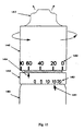
- Figure 1 shows an embodiment of a co-infusion device before it is activated.
- Figure 2 shows the embodiment of Fig. 1 after activation.
- Figure 3 shows the embodiment of Fig. 1 when charged with high pressure gas.
- Figure 4 shows the embodiment of Fig. 1 during discharge of the gas and drug solution.
- Figure 5A shows the detail of device operation corresponding to Fig. 1.
- Figure 5B shows the detail of device operation corresponding to Fig. 2.
- Figure 5C shows the detail of device operation corresponding to Fig. 3.
- Figure 5D shows the detail of device operation corresponding to Fig. 4.
- Figure 6 shows the embodiment of Fig. 1 and illustrates the charge/dose and dose rate adjustment features of the embodiment.
- Figure 7 shows the detail of position selection for controlling the dose rate.
- Figure 7A shows another view of the embodiment and shows certain details of the charge/dose features.
- Figure 8 shows a second embodiment of a device which may be particularly appropriate for inhalation of the gas.
- Figure 8A shows the detail of the flow rate adjustment and selection for the second embodiment.
- Figure 9 shows the embodiment of Figure 8 after perforation of the cap in a locked position.
- Figure 10 shows the embodiment of Figure 8 in the activated position.
- Figure 11 shows the embodiment of Figure 8 when dispensing gas.
- Figures 12 A-E show application of gas to the nose, mouth, both nostrils, eye and ear using an embodiment of a gas dispenser.
- Figure 13 shows an optional feature for dispensers which allows for dilution of the gas with ambient air.
- Figure 14 shows an optional differential flow adjustment feature including the use of a ball detent particularly useful for low flow dispensers.
- Figure 14A shows a cross-section detail of the embodiment of Figure 14A.
- Figure 14B shows a variation of the device of Figure 14 including the use of an alternative detent.
- Figure 14C shows a cross-section detail of the embodiment of Figure 14B.
- Figure 15 shows flow rate adjustment and selection details for the embodiment of Figures 14A and 14C.
- Figure 16A illustrates the analytical relationship between the critical needle taper angle α and the size of the annular orifice d for a needle displacement x.
- Figure 16B is a detailed illustration of a standard needle configuration with exemplary dimensions.
- Figure 16C is a detailed illustration of the preferred needle configuration with exemplary dimensions.
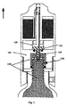
- Figs. 1-7 show a CO2 dispenser embodiment that illustrates a means for the co-infusion of CO2 with drugs. The dispenser embodiment in Figs. 1-7 is similar to the dispenser embodiments described for CO2 infusion in WO 01/03645 to which attention is directed as a cross-reference. However, in addition to a container of pressurized gas or vapor, a flow regulator, and an outlet, the present invention further includes a container of a quantity of drug-containing liquid or powder agent and a means for mixing and releasing a controlled dose of the drug agent and gas mixture through the outlet at a rate suitable for infusion into a body orifice such as the nose or mouth. Vertical motion in Figs. 1-5 and related figures is exaggerated to clarify the dispenser action. In the embodiments shown in Figs. 1-7 here a
collar 110 is screwed onto the CO2 cartridge neck 105. A set screw 111 in thecollar 110 prevents movement of thecollar 110 relative to thecartridge 101. Arotatable head 112 containing a seal-perforatingneedle 100, thedrug agent 115, and the means for its controlled mixing and ejection with CO2 is screwed into the fixedcollar 110 and is sealed to thecartridge sealing cap 106 by an O-ring gasket 117. As a safety feature the diameter of the sealingcap 106 above the location of the O-ring 117 should be less than the inside sealing diameter of the O-ring 117 so that any high pressure gas in theplenum 150 will be controllably released before the collar and head can be completely unscrewed and separated. - As shown in Fig. 1, the device is marketed with the sealing
cap 106 intact. Therotatable head 112 is screwed into the fixedcollar 110 only partially such that the perforatingneedle 100 does not penetrate thesealing cap 106. The sequence of operation of the co-dispenser shown in Figs. 1-4 is shown in enlarged detail in Figs. 5a-5d. - To activate the device initially, the
rotatable head 112 is screwed downward the full distance possible into the fixedcollar 110, causing theneedle 100 it contains to penetrate thecap 106 that seals thecartridge 101 as shown in Figs. 2 and 5b. Thereafter, when therotatable head 112 is unscrewed slightly thepoppet valve 120 on which theneedle 100 is mounted is closed and theneedle 100 is lifted out of theorifice 130 it formed in the cap. As shown in Figs. 3 and 5c, this causes thechamber 145 between thecap 106 and thepoppet valve 120 to become filled with high pressure CO2 gas 140. The volume of thegas dose chamber 145 is important since it defines the quantity of CO2 gas 140, i.e., the gas dose that is mixed and co-infused with the drug. - The
poppet valve 120 is biased shut against its O-ring-sealedseat 122 by aspring 125 that produces sufficient force to hold thepoppet valve 120 shut against the force of thehigh pressure gas 140 on it. This force need not be large since the area of theorifice 130 sealed by thepoppet valve 120 can be very small (a few mm2). When therotatable head 112 then is screwed downward theneedle 100 seats in and seals theorifice 130 in thecap 106 and thepoppet valve 120 is lifted as shown in Figs. 4 and 5d, allowing thehigh pressure gas 140 in thegas dose chamber 145 to escape as a controlled burst into thegas plenum 150 which has a much larger volume, reducing the pressure ten-fold or more. After the dose is administered, the pressure in the gas dose chamber would be about 1 atmosphere. From thegas plenum 150 the gas passes through theexit passage 126 and the venturi constriction of the passage. Thepoppet valve 120 is attached to aventuri control wire 121 that operatessleeve 123.Sleeve 123 is constructed to include a hole orgap 124. Thegap 124 is positioned in thesleeve 123 and the sleeve is positioned within the venturi region so that when thepoppet valve 120 is closed thegap 124 is not aligned with the opening to thecapillary passage 160. However, when thepoppet valve 120 is opened as it is during the controlled burst, theventuri wire 121 lifts thesleeve 123 so that thegap 124 is aligned with the opening to thecapillary passage 160. During the dose's passage through the venturi constriction, the controlled quantity of high velocity gas aspirates a correspondingly controlled amount ofdrug agent 115 through acapillary passage 160 from thedrug reservoir 115. The CO2/drug mixture 199 then is discharged as a dose of spray through a hole in the top 171 of the dispenser. Subsequent doses are ejected by repeating the charge and discharge sequence represented by Figs. 3 and 4 or Figs. 5c and 5d respectively. - The actions required by the user to execute this sequence are illustrated in Figs. 6 and 7. To activate the device initially the user screws in the
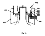
rotatable head 112 until it stops at the mark indicated as "Dose". The head is prevented from being unscrewed from its pre-activation position and is stopped at its fully screwed-in position by a slidingpin 180 in aslot 182 between thefixed collar 110 and therotatable head 112. These limiting positions correspond respectively to the positions shown in Figs. 1 and 2 (and to Figs. 5a and 5b) and are labeled "a" and "b" respectively in the schematic drawing of thepin 180 and slot 182 shown in Fig. 7. To deliver doses, the user first rotates the head against a torque-producingspring 655, which includes asection 654 that is engaged with thepin 180, to the charging position "c" in Fig. 7 corresponding to Figs. 3 and 5c, where thehead 112 becomes locked by thepin 180, now held in a retaining well 653. The user then applies the top of thedispenser 608 to his nose or mouth and pushes abutton 600 which releases the slidingpin 180 from its retaining well 653. Thehead 112 then rotates rapidly back to position "d" (corresponding to Figs. 4 and 5d) under the action of the spring, completing the dose-delivering sequence of processes described in the preceding paragraph. As shown in Fig. 6, subsequent doses are delivered simply by "cocking" the device by rotation as shown byarrow 602 and pushing abutton 600 to deliver the dose by an automatic counter-rotation. Note that left-handed screw threads are used in the embodiment shown, although a standard right-handed thread may also be employed. Accordingly, it is not necessary for the user to observe the position of the head relative to thecollar 110 since the action involves rotation from the limiting position a in one direction to the limiting position d in the opposite direction. It will be clear to those of ordinary skill in the art that this same type of automatic action can be obtained also by combining a rotary cocking action with a triggered linear return between the charging and dose positions such as is found in the action of retractable ball-point pens. - For a device designed to dispense a particular drug, the volume of CO2 gas in a dose, the quantity of drug that it aspirates and the rate of infusion of the mixture has to be chosen carefully. Obviously, the quantity of drug in a dose should be that determined in clinical trials and selected to be the most effective under a given set of circumstances, taking into account the enhanced effect of the drug caused by the co-application of CO2. However, the quantity of CO2 accompanying each drug dose may not necessarily be that determined in clinical trials to obtain the optimum potentiation, since both the quantity and concentration of CO2 infused and the rate of its infusion must be acceptable to the user.
- The relative quantities of drug and CO2 in the dispensed mixture are determined by the relative diameters of the
capillary opening 161 and theventuri throat 155. The rate of discharge of the mixture is limited by the series flow impedance from thedose chamber 145 through thepoppet valve 120,plenum 150, andventuri 155. Generally, the tolerable steady flow rate of gaseous CO2 into the nose is in the range 2-10 cc/sec for at least 2 seconds corresponding to the approximate volume of the nasal and sinus passages. However, patients may develop a short-term tolerance after continuous use or successive uses that allows for a higher flow rate. In addition, the inventors have access to new experimental evidence that suggests that under certain circumstances much higher initial flow rates, on the order of 1 to 2 liters/minute may not only be tolerated, but be beneficial, in relief of certain symptoms. The tolerable CO2 infusion rate is more than 10 cc/sec for an indefinitely long period into the mouth. However, although other designs may be appropriate in specific circumstances, in a dispenser for general adult use that includes nasal infusion, thegas dose chamber 145 at minimum can contain an amount of gas corresponding to 4-20 cc at room temperature and atmospheric pressure. If the CO2 pressure in thecartridge 101 and in thedose chamber 145 is nominally about 60 atmospheres (which is achievable by known cartridge designs -- although such cartridges are not necessarily currently marketed for medical use), the volume of thedose chamber 145 should be in the range 0.07-0.33 cc, equivalent to a cubic chamber with 4-7 mm edge length. The diameter and height of thegas dose chamber 145 therefore need to be only slightly larger than the typical 3 1/2 mm sealing cup diameter of currently available cartridges. A different size gas dose chamber would, of course, be required given different pressure, desired volume of gas, or other changes in the assumptions described. The concentration of the drug solution and the relative sizes of theventuri 155 andcapillary openings 161 are chosen for the expulsion of this quantity of CO2 to aspirate the clinically appropriate drug dose (typically 10-60 mg for many drugs), although trials may show that some individuals prefer more than one application of CO2 to obtain a full drug dose. - Because the desirable flow rate of gaseous CO2 has been found to be highly user-subjective, it is preferable to have a means for the user to select the dose speed, i.e., the period over which the gas and drug dose is delivered as a pulse. After the device is activated as is shown in Fig. 2 and 5b, the dose speed can be modified conveniently and simply in the illustrative embodiment by loosening the set-screw 111 that prevents collar rotation, unscrewing the
collar 110 to the desired,marked positions 609 as shown in Fig. 6, and re-tightening the set-screw 111. The fastest dose delivery is obtained in the post-activation position (Figs. 2 and 5b) since thepoppet valve 120 is opened fully in that position, but if thecollar 110 is unscrewed, thepoppet valve 120 is adjusted so that it is only very slightly open when the head is at position "d". That position would correspond to the minimum flow rate required for aspiration of the proper quantity of drug. The range of adjustment between the positions of thecollar 110 giving maximum and minimum permissible flow rates, shown as "F" and "S" in Fig. 6, is limited by the width of theslot 182 in the threadedcartridge neck 105 in which the set-screw 111 is seated. - The embodiment of the invention described above is a means for co-infusion or co-inhalation of a CO2 /drug mixture as a measured dose into the nasal and respiratory passages. That device and the devices described in WO 01/03645 are not generally suitable for inhalation of CO2 into the lungs to potentiate the effect of drugs applied by other means. During inhalation the CO2 is mixed with inspired air; therefore, a flow rate and quantity of CO2 much greater than that achievable with the dispenser embodiments previously described is necessary. The required flow rate for co-application of drugs and of CO2 by inhalation, and the means for achieving the required flow rate in a portable device are now described.
- In general, depending on the size and other attributes of the individual, 1 to 2 liters of air inspired over a period of 1 to 2 seconds is comfortable for most adults. This corresponds to a flow rate range of 1 to 4 liters/second of air. The concentration of CO2 in expired breath is about 6%. Most experimental research with inhalation of CO2 by humans and animals has employed maximum concentrations of approximately 10%-70% CO2 in air. However, above 10% concentration the individual may suffer a feeling of suffocation, and above 30% continued inhalation will result in the individual losing consciousness. If a 10% concentration of CO2 is desired, a dispenser that provides a controlled flow rate in the range 100-400 cc/sec is needed. This is more than an order of magnitude greater than the typical maximum tolerable initial flow rate for infusion of 100% CO2 into the respiratory passages for which the previously described embodiments are suitable.
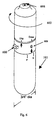
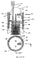
- Figs. 8-11 show a dispenser embodiment for controllably delivering CO2 at an adjustable rate in the 100-400 cc/sec range suitable for co-application of CO2 with drugs by inhalation or for treatment of asthma and other conditions by inhalation of CO2 alone. The dispenser embodiment in Figs. 8-11 is similar to that described for CO2 infusion in WO 01/03645 in that it is a hand-held portable dispenser consisting of a pressurized cylinder of CO2 screwed into a dispenser head assembly. The CO2 cartridge 801 in this embodiment has a threaded
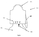
neck 805 and a plug-type sealing cap 806 and is screwed into a dispenser head with a seal-perforatingneedle 800 similar to that described in WO 01/03645. In the device as marketed to the user, thecartridge 801 is screwed into thehead 812 until the tip of theneedle 800 just touches the top of the intact sealing cap 806 (i.e. without penetrating it) as shown in Fig. 8. The user activates the device by screwing thecartridge 801 onto the needle-bearinghead 812 as indicated byarrow 816, thus perforating the sealingcap 806. The user may select the rate at which the device can deliver CO2 gas by choosing the distance that theneedle 800 penetrates thecap 806, and thereby the size of theorifice 830 produced in the cap. The device would be activated by unscrewing the head and depressing the lever to release the gas. The degree of rotation required to produce each selectable rate may be indicated by number or other indicator markings on the dispenser head as shown in Fig. 8a. - However, while it is possible to select the flow rate by screwing the
cartridge 801 only part way onto thehead 812 to achieve the degree of seal perforation by theneedle 800 required to obtain that rate, it is preferable to screw thecartridge 801 andhead 812 together as far as possible, making the maximum possible orifice in thesealing cap 806. In this position, which is shown in Fig. 9, gas cannot be released from thecartridge 801 since theneedle 800 is locked in its fully seated position. The user can select this position, therefore, to carry the device without risk of unintentional release of CO2 gas. Since both the pressure in the cartridge and the orifice size are known, the maximum flow rate is also known. As shown in Fig. 8A, in this preferred embodiment, the device is activated for use by partially unscrewing thehead 812 as is indicated byarrow 817, shown in Fig. 10, until thearrow 802 on thecartridge 801 is opposite the marking 831 on thehead 812 that indicates the flow rate that the user desires. This flow rate is essentially a portion of the known maximum flow rate permitted by the size of the orifice, and the markings may be anarrow 802 on the cartridge andnumbers 831 on the head that represent either a percentage of the maximum flow or the number of cc/sec. - Upon activation, the
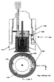
head 812 andcartridge 801 are in the position shown in Fig. 10. In the present embodiment theneedle 800 is held firmly seated in thecap orifice 830 by the force of aspring 829 acting on a slidingneedle mount 834 as shown in Fig. 10, thus preventing flow of gas from thecartridge 801. In thepresent embodiment gas 866 can be controllably released up to the desired flow rate by depressing the dispensinglever 815 as shown in Fig. 11. Thelever 815 lifts the slidingneedle mount 834 and thereby unseats theneedle 800 to open, directly and variably without rotating thehead 812, theorifice 830 in thecartridge 801 seal to obtain the desired high flow rate. A compressible (sponge-type)gasket ring 852 seals the dispenser lever penetration and threads to prevent excessive gas leakage from the low pressure gas region. When thelever 815 is released, thespring 829 returns theneedle mount 834 andneedle 800 to the fully seated position as in Fig. 10, terminating thegas flow 866 from the openings in the top of thehead 871. To repeat the flow, the user again presses and releases the dispensinglever 815. After the dispensing process is completed, the user can screw the head back to the locked position shown in Fig. 9 for secure transport in a pocket or purse. - The direct lever-actuated motion of the
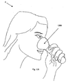
needle sliding mount 834 permits the greater linear motion of theneedle 800 out of theorifice 830 that is required to obtain a high flow rate. Therefore, provided that theorifice 830 is large enough, using this device, the user can selectively obtain the higher flow rates needed for inhalation of CO2. The controllability and simplicity of the needle-in-cap flow rate selection and adjustment, employed in previously described embodiments, is retained without the requirement of a large or coarse rotation of the head to a high flow position. - It is also possible to potentiate drug action solely by mucosal infusion. While generally, infusion is best performed using an initial lower flow rate, on the order of .5 cc/second to 20 cc/second depending on the tolerance of the particular individual, certain applications allow and may even require a high initial flow rate. The lever activated embodiment may be modified to provide a low flow rate, but the rotably activated embodiments described in WO 01/03645 are also suitable, and indeed any low flow source of gas could be used. The general method of application is as follows: the selected drug is applied by any standard method including but not limited to inhalation, pills, capsules, injection, or epidural patch. As shown in Fig. 12A-B, the individual P then infuses oral and nasal mucous membranes by placing the source of low flow rate CO2 or other appropriately physiologically active gas or vapor in or around a facial orifice, such as the mouth or nostril, while substantially inhibiting the flow of the CO2 into the trachea and lungs by limiting inhalation of the CO2. If the mouth is infused the gas is allowed to exit from the nostrils. Alternatively, one or both nostrils may be infused either by using the dispenser head shown in Fig. 12B or by use of a cup or similar device that covers both nostrils as shown in Fig. 12E. The gas is allowed to flow from a remaining open orifice, i.e., either the mouth, the uninfused nostril, or both as appropriate. Completely holding the breath is not necessary to substantially prevent inhalation of the CO2. With practice, it is possible for the individual to breathe through an uninfused orifice: for example, if one nostril is infused and the gas is allowed to exit though the other nostril, it is possible for the individual to breathe through the mouth without substantial inhalation of the infused gas. The eye or eyes may also be infused using a cup as shown in Fig. 12C or merely by holding a hand over the eye and releasing the gas between the hand and the eye. Persons of ordinary skill in the art will appreciate that a double cup could be developed to infuse both eyes simultaneously, and similarly appropriate heads could be developed to infuse the mouth and one nostril. The ear or ears may also be infused as shown in Fig. 12D. Note that a similar process may be used with the first embodiment to infuse a mixture of a drug and gas into various facial orifices.
- Infusion can be continued to the limit of tolerance or until the desired potentiation effect is realized. Since most individuals develop a temporary increased tolerance after extended applications or repeated applications, it may be possible and desirable to increase the duration of additional infusions after a few applications when all applications occur within a short time of each other, i.e., approximately 1 to 20 minutes between each application.
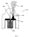
- As shown in Fig. 13, a
venturi 1303 region can be added to thedispenser head 1312 that allows a quantity of ambient air to be mixed with the CO2 dispensed. Thehigh pressure CO 2 1350 flows past theneedle 1300 and becomeslow pressure CO 2 1351. The low pressure CO2 moves past theair inlet 1333 and mixes with ambient air. The concentration of CO2 in the dispensedgas 1352 will thus be lower than 100% to the degree that air is admitted into theair inlet 1333. This will, in part, be a function of the size of theair inlet 1333. Additionally, the user can place his finger wholly or partially over theinlet 1333 to adjust the CO2 concentration to that which is optimum for him at a given time, e.g., at a given stage of nasal inflammation or other mechanical partial blocking means may be used with the same effect. This dilution feature also extends the duration of application obtainable from the dispenser for a fixed quantity of CO2. - With reference to Fig. 14, in the initial embodiments described in WO 01/03645, the flow of CO2 is adjusted by screwing the cartridge neck into and out of the dispenser head, thereby moving the needle into and out of the orifice in the cartridge seal. Although this is an extremely simple and practicable means for flow adjustment, it requires an extremely fine thread on the cartridge neck especially for the conventional needle size and shape described in Fig. 4A of WO 01/03645. This can be understood by considering that the axial movement of the needle required to obtain the required 2-10 cc typical flow rate is in the vicinity of 0.025-0.050 mm (1-2 thousandths of an inch (mils)). For the standard threaded cartridge using approx. 1 thread per mm (actually 24 threads per inch), this means that the full range of flow rate adjustment is obtained with rotation of the head less than 1/20th of a turn (less than 20°). As described in WO 01/03645, the required rotation for convenient control of the typical maximum flow rate is in the range of 30° to 120°, with the optimum being near but less than 120° rotation. This means that a very fine thread on the
cartridge neck 1405, more than 4 threads per mm (100 threads per inch), is required to approach the optimum degree of flow rate control by the means described in WO 01/03645. - While the production of such very fine threads is possible in principle, their production in a mass-produced low-cost device may be impractical for several reasons. First, machining such fine high-precision threads is substantially more expensive than machining standard threads on cartridge necks, and such threads would be expensive to produce on a molded plastic head. Second, cartridge threads now are generally protected from corrosion by applying a coating that would fill and clog fine threads. Third, it is impractical to hand-assemble items with such very fine threads because highly precise alignment is required to avoid cross-threading, resulting in a need for an expensive high-precision assembly machine.
- Figs. 14 and 14A illustrate an embodiment of a low flow dispenser incorporating a differential screw threads that allow the user to obtain the required degree of rotational control with relatively coarse and easily produced threads. A three-part assembly consisting of a
head 1412, asleeve 1440 and acollar 1410 is used. Thehead 1412 is similar to the dispenser heads in other embodiments, including those in WO 01/03645 in that it incorporates a perforating and flow-regulatingneedle 1400 along with ports in the top of thehead 1413 for delivering thehigh pressure gas 1495 in the container as the low pressure dispensedgas 1414. Thecollar 1410 is screwed onto the CO2 cartridge neck 1405 and selectively fixed there against rotation, e.g. by a set screw (not shown) as in the co-infusion embodiment in Figs. 1-4. Thehead 1412 also is fixed against rotation bytabs 1417 that extend from thehead 1412 intoslots 1418 in thecollar 1410, permitting axial relative motion between thehead 1412 andcollar 1410 but not rotational relative motion between them. A spring orgasket 1493 is situated between thehead 1412 andcollar 1410. Thesleeve 1440 is threaded over both thehead 1412 andcollar 1410, bridging the space between them and thereby determining their relative axial positions. - The
meshing threads 1490 between thecollar 1410 and thesleeve 1440 are slightly coarser than those 1491 between thehead 1412 and thesleeve 1440. Thus, as thesleeve 1440 is rotated relative to thehead 1412 andcollar 1410, the distance between thehead 1412 and the collar/cartridge assembly is changed. For example, if there are 1.04 threads/mm (24 threads/inch in the collar end of the sleeve and 0.96 threads/mm (26 threads/inch) in its head end, a single turn of the sleeve relative to the head and collar/cartridge assembly advances the collar/cartridge assembly into the sleeve by 1.04mm (1/24 inch) but withdraws the head from the sleeve by only 0.96 mm (1/26 inch); therefore, the distance between the head and collar/cartridge assembly is decreased by 0.08 mm (1/24-1/26 = 2/624 = 0.0032 inch =3.2 mils), which also is the distance that theneedle 1400 is advanced into thecartridge 1401 by a 360° turn of the sleeve. It can be seen that the required ~0.025 mm (~1-mil) motion of theneedle 1400 into and out of thecartridge orifice 1430 may be obtained with the near-optimum 120° rotation of the sleeve using easily produced coarse threads. Another advantage of the configuration in this embodiment is that adetent ball 1426 andslot 1428arrangement 1425, including a limitingslot 1496 can be incorporated easily into the head/sleeve assembly as shown in Fig. 14 without requiring the cartridge manufacturer to produce a special slotted thread in the cartridge neck. With specific reference to Figures 14B-C, as an alternative, other detent arrangements, such as apawl 1497, could also be used, and persons of ordinary skill in the art will appreciate that other alternatives are also available. - Fig. 15 illustrates the flow rate adjustment and selection features that may be incorporated into the embodiment of Fig. 14. The
collar 1410 is fully screwed into thesleeve 1440 so that thecollar arrow 1454 is at the position indicated as "0" 1453 on thesleeve 1440, and thecartridge 1401 is screwed into thecollar 1410 until the tip of theneedle 1400 just touches the top of the intact sealing cap 1406 (i.e. without penetrating it). The user activates the device by screwing thecartridge 1401 into the collar until thearrow 1451 on thecartridge 1401 is opposite the number on thecollar 1452 that indicates the maximum flow rate that the user desires, which corresponds to the degree of seal perforation by theneedle 1400 required to obtain that maximum rate. Thereafter, by rotating thesleeve 1440 the user can select the desired portion of that maximum flow delivered (which may be expressed by sleeve indicator number marks 1453 as a percent of the maximum flow) by rotating thesleeve 1440, to the correspondingsleeve indicator number 1453 position opposite thecollar arrow 1454 or by counting the number of detent "clicks" corresponding to that position. - As described in WO/03645 the preferred needle configuration allows the desired very small change in the orifice area to be effected by relatively large axial displacement of the needle.
- While such modification is of primary advantage when used in conjunction with the embodiments shown in WO 01/03645, this modification may also have advantages in the lever embodiment shown herein or in any embodiment in which it is desirable that a large displacement of the needle produce only small change in the flow.
- An appropriate needle configuration is shown in Fig. 16C. The lowermost point of the needle 1603, over a distance approximately equal to the thickness of the cartridge seal, has essentially the same shape and size as the puncture point shown in Figure 4A of WO 01/03645 and shown here in Figure 16B. The configuration of this point is an optimum compromise between the strength of a blunt point and the reduced force requirement of a sharp point in the puncture process. However, the
needle region 1602 above the point which is adjacent to the orifice formed in the cap, determines the size of the annular flow-controlling orifice when the needle is partially withdrawn. Thus, the modification of the configuration of this region of the needle may be used to obtain the required flow regulation characteristics of the dispenser. - As shown in Fig. 16A, the axial needle displacement giving a required size of the flow-controlling annular orifice is inversely dependent on the taper angle of the needle in the
seat region 1602. This taper angle is approximately 20 degrees in the initial needle configuration shown in Fig. 16B, which required a displacement x of about 0.025 mm (about 0.001 inch) between zero flow and full flow as obtained by a 10 degree rotation of the head with 28 threads/inch. Therefore, to obtain the 120 degree optimal head rotation, the needle seat taper angle α must be about 1.7 degrees for 0.89 threads/mm (28 threads/inch) or about 3 degrees as indicated by α2 for the preferred 0.52 threads/mm (48 threads/inch). - While preferred embodiments of the present invention are described above and in the following claims, it is contemplated that various modifications may be made without departing from the scope of the invention as defined by the appended claims. For example, while CO2 has been particularly described, other gaseous and vaporous vasodilators including NO and dilute acid vapors, as well as other physiologically active, gaseous substances (e.g., vasoactive, neuroactive, myoactive, etc.), have similar potentiating effects and are intended to be included as possible choices for substances to be co-applied with a drug for the purpose of increasing and/or controlling the effect of the drug.
said head further comprising said reservoir and a capillary passage connecting the reservoir and the venturi region of the exit passage;
and wherein said needle is attached to the valve and positioned such that the needle perforates the cap when the opening and cap are in a first preselected position within the chamber and forms an orifice of a desired size; and such that when the opening and cap are in the first preselected position, the needle seals the orifice and the valve is forced open; and including
a lock for holding the opening and cap in a second preselected position within the chamber wherein the needle is at least partially removed from the orifice and the valve is closed, whereby the chamber is filled with the gaseous potentiating substance at a high pressure;
a first spring for moving the opening and cap relative to the chamber to the first preselected position when the lock is released, whereby the gaseous potentiating substance moves from the chamber to the outlet, passing through the plenum and the venturi region of the exit passage, and aspirating a selected amount of the aspiratable agent that contains the drug, discharging a mixture of the drug and the gaseous potentiating substance at the outlet.
Claims (8)
- A device for generating a flow of a mixture of a selected drug and a gaseous potentiating substance for administration to an individual comprising:a container [101] for pressurized holding of the gaseous potentiating substance, defining an opening sealed with a cap [106];a needle [100] adapted for perforating the cap [106];a reservoir [115] adapted for holding an aspiratable agent that contains the drug;an outlet [170] for discharge of a mixture of said drug and said gaseous potentiating substance; anda dispensing region adapted for applying a discharge from the outlet [170] to a facial orifice of the individual;characterised in that said device further includes:a head [112] adapted for attachment to the container [101],said head [112] defininga chamber [145] wherein when the head [112] is attached to the container [101] the opening is within the chamber [145] and wherein the opening and cap [106] are axially translatable to various positions within the chamber [145],a plenum [150],an exit passage [126] andat least one outlet [170],wherein the plenum [150] is connected to the outlet [170] by means of the exit passage [126], said exit passage [126] forming a venturi region [155] near the outlet [170], and wherein the chamber [145] selectively communicates with the plenum [150] by means of a valve [120], said valve [120] being biased to a closed position;
said head [112] further comprising said reservoir [115] and a capillary passage [160] connecting the reservoir [115] and the venturi region [155] of the exit passage [126];
and wherein said needle [100] is attached to the valve [120] and positioned such that the needle [100] perforates the cap [106] when the opening and cap [106] are in a first preselected position within the chamber [145] and forms an orifice [130] of a desired size; and such that when the opening and cap [106] are in the first preselected position, the needle [100] seals the orifice [130] and the valve [120] is forced open; and including
a lock for holding the opening and cap [106] in a second preselected position within the chamber [145] wherein the needle [100] is at least partially removed from the orifice [130] and the valve [120] is closed, whereby the chamber [145] is filled with the gaseous potentiating substance at a high pressure;
a first spring [655] for moving the opening and cap [106] relative to the chamber [145] to the first preselected position when the lock is released, whereby the gaseous potentiating substance moves from the chamber [145] to the outlet [170], passing through the plenum [150] and the venturi region [155] of the exit passage [126], and aspirating a selected amount of the aspiratable agent that contains the drug, discharging a mixture of the drug and the gaseous potentiating substance at the outlet [170]. - The device of claim 1 wherein the dispensing region is adapted to apply the discharge to a nostril of the individual.
- The device of claim 1 wherein the dispensing region is adapted to apply the discharge to the individual's mouth.
- The device of claim 1 further comprising:a collar adapted to be fixedly attached to the container, wherein the head is simultaneously attachable to the container and the collar.
- The device of claim 1 wherein the first preselected position may be selected and modified by the user.
- The device of claim 5 wherein the collar further includes markings corresponding to a range of possible first preselected positions.
- The device of claim 1 wherein the container holds the gaseous potentiating substance of approximately 60 atmospheres and the volume of the chamber is between 0.07 and 0.33 cc.
- The device of claim 1 wherein the valve is biased closed by a second spring.
Applications Claiming Priority (5)
| Application Number | Priority Date | Filing Date | Title |
|---|---|---|---|
| US16412599P | 1999-11-08 | 1999-11-08 | |
| US164125P | 1999-11-08 | ||
| US18549500P | 2000-02-28 | 2000-02-28 | |
| US185495P | 2000-02-28 | ||
| PCT/US2000/041956 WO2001036018A2 (en) | 1999-11-08 | 2000-11-07 | Method and apparatus for relieving ailments using gases to increase the effectiveness of drugs |
Publications (3)
| Publication Number | Publication Date |
|---|---|
| EP1237610A2 EP1237610A2 (en) | 2002-09-11 |
| EP1237610A4 EP1237610A4 (en) | 2003-06-04 |
| EP1237610B1 true EP1237610B1 (en) | 2006-05-10 |
Family
ID=26860285
Family Applications (1)
| Application Number | Title | Priority Date | Filing Date |
|---|---|---|---|
| EP00992143A Expired - Lifetime EP1237610B1 (en) | 1999-11-08 | 2000-11-07 | Apparatus for co-application of gases and drugs |
Country Status (8)
| Country | Link |
|---|---|
| US (4) | US6959708B1 (en) |
| EP (1) | EP1237610B1 (en) |
| JP (1) | JP2004500168A (en) |
| AT (1) | ATE325633T1 (en) |
| AU (1) | AU779413B2 (en) |
| CA (1) | CA2389294A1 (en) |
| DE (1) | DE60027921D1 (en) |
| WO (1) | WO2001036018A2 (en) |
Cited By (5)
| Publication number | Priority date | Publication date | Assignee | Title |
|---|---|---|---|---|
| WO2011147714A1 (en) * | 2010-05-25 | 2011-12-01 | British American Tobacco (Investments) Limited | Aerosol generator |
| US8578942B2 (en) | 2010-05-25 | 2013-11-12 | British American Tobacco (Investments) Limited | Aerosol generator |
| US8689786B2 (en) | 2010-05-25 | 2014-04-08 | British American Tobacco (Investments) Limited | Aerosol generator |
| DE202017106349U1 (en) | 2017-10-20 | 2017-11-22 | Joachim Blum | Hand device for enriching CO2 in the breathing air |
| KR20220002084U (en) * | 2021-02-18 | 2022-08-25 | 주식회사 다우기업 | Applicator vessel for a pet |
Families Citing this family (55)
| Publication number | Priority date | Publication date | Assignee | Title |
|---|---|---|---|---|
| US7017573B1 (en) * | 1999-07-12 | 2006-03-28 | Capnia, Incorporated | Methods and apparatus for relieving headaches, rhinitis and other common ailments |
| EP1237610B1 (en) * | 1999-11-08 | 2006-05-10 | Capnia Incorporated | Apparatus for co-application of gases and drugs |
| US20070039615A1 (en) * | 1999-11-08 | 2007-02-22 | Capnia, Incorporated | Methods and apparatus for treating rhinitis |
| US20060172017A1 (en) * | 1999-11-08 | 2006-08-03 | Capnia, Incorporated | Methods and apparatus for the enhanced delivery of physiologic agents to tissue surfaces |
| US20110301569A1 (en) * | 2001-01-20 | 2011-12-08 | Gordon Wayne Dyer | Methods and apparatus for the CVCS |
| ATE453421T1 (en) | 2002-05-09 | 2010-01-15 | Glaxo Group Ltd | LIQUID DISPENSING DEVICE |
| US7681572B2 (en) | 2002-08-20 | 2010-03-23 | Aga Ab | Method and devices for administration of therapeutic gases |
| US7337776B2 (en) | 2002-08-20 | 2008-03-04 | Aga Ab | Methods for easing pain and anxiety from atrial or ventricular defibrillation |
| GB0322284D0 (en) * | 2003-09-23 | 2003-10-22 | Glaxo Group Ltd | Medicament dispenser |
| AU2004287261B8 (en) | 2003-11-03 | 2011-01-27 | Glaxo Group Limited | A fluid dispensing device |
| GB0405477D0 (en) | 2004-03-11 | 2004-04-21 | Glaxo Group Ltd | A fluid dispensing device |
| AU2005210415A1 (en) * | 2004-02-04 | 2005-08-18 | Major Tsushin Co., Ltd. | Gas jetting device and spraying device |
| GB0402692D0 (en) * | 2004-02-06 | 2004-03-10 | Glaxo Group Ltd | A fluid dispenser |
| GB0402690D0 (en) * | 2004-02-06 | 2004-03-10 | Glaxo Group Ltd | A fluid dispenser |
| GB0402697D0 (en) * | 2004-02-06 | 2004-03-10 | Glaxo Group Ltd | A fluid dispenser |
| GB0402693D0 (en) * | 2004-02-06 | 2004-03-10 | Glaxo Group Ltd | A fluid dispenser |
| GB0402691D0 (en) * | 2004-02-06 | 2004-03-10 | Glaxo Group Ltd | A fluid dispenser |
| GB0402695D0 (en) * | 2004-02-06 | 2004-03-10 | Glaxo Group Ltd | A metering pump system |
| GB0402694D0 (en) * | 2004-02-06 | 2004-03-10 | Glaxo Group Ltd | A fluid dispenser |
| GB0507224D0 (en) | 2005-04-09 | 2005-05-18 | Glaxo Group Ltd | A fluid dispensing device |
| US9358150B2 (en) | 2005-05-13 | 2016-06-07 | Benechill, Inc. | Methods and devices for non-invasive cerebral and systemic cooling alternating liquid mist/gas for induction and gas for maintenance |
| US7824436B2 (en) | 2005-05-13 | 2010-11-02 | Benechill, Inc. | Methods and devices for non-invasive cerebral and systemic cooling |
| US8721699B2 (en) * | 2005-05-13 | 2014-05-13 | Benechill, Inc. | Methods and devices for non-invasive cerebral and systemic cooling |
| HUP0600765A2 (en) * | 2006-10-06 | 2008-10-28 | Istvan Piller | Container for stable carbondioxide foam, process for producing stable carbondioxide foam and method for using of foam |
| US11185671B2 (en) * | 2006-11-27 | 2021-11-30 | Frank Levy | Apparatus and process for producing CO2 enriched medical foam |
| US11833320B2 (en) | 2006-11-27 | 2023-12-05 | Frank Levy | Apparatus and process for producing CO2 enriched medical foam |
| JP4994805B2 (en) * | 2006-11-27 | 2012-08-08 | 株式会社吉野工業所 | Nasal spray dispensing nozzle |
| US10350399B2 (en) | 2006-11-27 | 2019-07-16 | Frank Levy | Apparatus and method for producing an enriched medical suspension of carbon dioxide |
| US10322271B2 (en) | 2006-11-27 | 2019-06-18 | Frank Levy | Delivery system and method for the effective and reliable delivery of controlled amounts of a medical fluid |
| JP4907318B2 (en) * | 2006-11-30 | 2012-03-28 | 株式会社吉野工業所 | Dispenser |
| US20080249482A1 (en) * | 2007-04-05 | 2008-10-09 | Miki Erez | Self catheterization kit |
| US20100174278A1 (en) * | 2008-11-07 | 2010-07-08 | Denise Barbut | Methods of nasopharyngeal cooling for augmenting coronary perfusion pressure |
| US20100168602A1 (en) * | 2008-12-30 | 2010-07-01 | Searete Llc | Methods and systems for presenting an inhalation experience |
| SI3210644T1 (en) * | 2009-05-27 | 2019-03-29 | Ino Therapeutics Llc | Devices for engaging indexed valve and pressurized canister assembly with collar |
| CN102802717A (en) * | 2009-06-19 | 2012-11-28 | 贝尼奇尔股份有限公司 | Devices for cooling the nasal cavity |
| GB2475341A (en) * | 2009-11-17 | 2011-05-18 | Pa Knowledge Ltd | Propelled delivery of powder treatments to the eye |
| BR112012030660A2 (en) | 2010-06-01 | 2016-08-16 | Capnia Inc | gas dispenser for dispensing accurate doses of therapeutic gas from a reservoir containing highly compressed therapeutic gas |
| JP5093762B2 (en) * | 2010-07-28 | 2012-12-12 | Toto株式会社 | Sanitary washing device |
| WO2012024401A2 (en) * | 2010-08-17 | 2012-02-23 | University Of Florida Research Foundation, Inc. | Intelligent drug and/or fluid delivery system to optimizing medical treatment or therapy using pharmacodynamic and/or pharmacokinetic data |
| GB201016797D0 (en) * | 2010-10-06 | 2010-11-17 | British American Tobacco Co | Aerosol generator |
| IN2014DN07474A (en) * | 2012-02-16 | 2015-04-24 | Capnia Inc | |
| US11554229B2 (en) | 2013-03-26 | 2023-01-17 | OptiNose Inc. | Nasal administration |
| SG11201507981TA (en) * | 2013-03-26 | 2015-10-29 | Optinose As | Nasal administration |
| EP4205699A1 (en) * | 2014-03-31 | 2023-07-05 | Boehringer Ingelheim Vetmedica GmbH | Inhaler |
| WO2015149922A2 (en) | 2014-03-31 | 2015-10-08 | Boehringer Ingelheim Vetmedica Gmbh | Inhaler |
| DE102014011271A1 (en) * | 2014-07-29 | 2016-02-04 | Pari GmbH Spezialisten für effektive Inhalation | Ballast chamber with control element for inhaler |
| EP3095522A1 (en) | 2015-05-20 | 2016-11-23 | Aptar Radolfzell GmbH | Inhalation device, inhalation device set and associated nozzle plate |
| MX2018010266A (en) | 2016-02-26 | 2019-03-28 | Nanotech Energy Inc | Methods, devices and systems for processing of carbonaceous compositions. |
| US10933204B2 (en) * | 2017-06-01 | 2021-03-02 | Counteract, Llc | Prescription bottle cap capable of administering opioid overdose reversal agent |
| WO2019118871A1 (en) * | 2017-12-14 | 2019-06-20 | Respiderm Corporation | Method and apparatus for therapeutic gas treatment |
| US10597206B2 (en) | 2018-06-15 | 2020-03-24 | Kenneth Corey | Medicine container cover |
| US11717656B2 (en) | 2019-03-20 | 2023-08-08 | Gyros ACMI Inc. | Delivery of mixed phase media for the treatment of the anatomy |
| US11918735B2 (en) | 2019-05-24 | 2024-03-05 | Pure Scientific Technologies, Inc. | Dual metered inhaler |
| CN110433366B (en) * | 2019-08-12 | 2022-03-04 | 杭州市红十字会医院 | Portable department of respiration ware of dosing |
| WO2023154815A2 (en) * | 2022-02-09 | 2023-08-17 | Respiderm Corporation | Gas cylinder adapter assembly for apparatus for therapeutic gas treatment and methods thereof |
Citations (1)
| Publication number | Priority date | Publication date | Assignee | Title |
|---|---|---|---|---|
| WO2001003645A2 (en) * | 1999-07-12 | 2001-01-18 | Capnia, Incorporated | Methods and apparatus for relieving headaches, rhinitis and other common ailments |
Family Cites Families (86)
| Publication number | Priority date | Publication date | Assignee | Title |
|---|---|---|---|---|
| US3127058A (en) * | 1964-03-31 | Oxygen dispensing device | ||
| US1288850A (en) * | 1918-01-12 | 1918-12-24 | Harvey E Easly | Oxygen-inhaling device. |
| US1449047A (en) | 1922-04-01 | 1923-03-20 | Johnson Godwin Harry | Pocket inhalation apparatus |
| BE333198A (en) * | 1925-03-28 | |||
| GB408856A (en) | 1933-08-14 | 1934-04-19 | Wietske Van Seters Bosch | Improvements in and relating to inhalers |
| US2205938A (en) * | 1939-07-13 | 1940-06-25 | Knapp Monarch Co | Liquid dispensing device |
| CH247873A (en) | 1945-02-06 | 1947-03-31 | Albert Bischoff Anton | Device for introducing medicinal substances and fragrances into the nostrils. |
| US2593552A (en) * | 1947-02-03 | 1952-04-22 | Marvin L Folkman | Aerosol dispenser and penetrable cartridge therefor |
| US2651303A (en) | 1948-11-13 | 1953-09-08 | Richard S Johnson | Inhaler |
| US2596415A (en) * | 1949-02-21 | 1952-05-13 | Knapp Monarch Co | Spraying device |
| US2585254A (en) * | 1949-02-21 | 1952-02-12 | Knapp Monarch Co | Spraying device |
| DE837158C (en) | 1949-06-10 | 1952-04-21 | Draegerwerk Ag | Anesthetic equipment |
| US2574028A (en) * | 1949-08-16 | 1951-11-06 | Abbott Lab | Gas container and dispensing means |
| US2677373A (en) * | 1952-05-19 | 1954-05-04 | P M Ind Inc | Plastic injection device |
| US2860634A (en) * | 1955-05-18 | 1958-11-18 | Res Lab Inc | Oxygen dispensing device and nose piece combination |
| US2920623A (en) | 1957-08-26 | 1960-01-12 | Holt Jerome James | Pocket oxygen dispenser |
| US3314429A (en) * | 1964-09-14 | 1967-04-18 | Scherer Corp R P | Gelatin capsule with dispenser |
| US3425414A (en) * | 1965-05-28 | 1969-02-04 | William J La Roche | Inhalant dispenser |
| US3361298A (en) * | 1965-10-06 | 1968-01-02 | John G. Trumble | Camping unit fuel tank filler spout cap assembly |
| DE1491660A1 (en) * | 1966-11-15 | 1969-08-28 | Oswald Brunn | Miniair small oxygen and filter ventilator with various combinations |
| US3513843A (en) | 1967-07-05 | 1970-05-26 | Gertrude Exler | Respiratory device for rebreathing carbon dioxide |
| US3934585A (en) | 1970-08-13 | 1976-01-27 | Maurice David M | Method and apparatus for application of eye drops |
| US3776227A (en) * | 1972-01-31 | 1973-12-04 | I Pitesky | Portable hyperventilation relieving device |
| US3870072A (en) * | 1973-05-10 | 1975-03-11 | Lindemann Hans Joachim | Insufflation apparatus for introducing limited quantities of carbon dioxide into the human body for operative purposes |
| US3974830A (en) * | 1975-01-27 | 1976-08-17 | Laverne Albert A | Method and apparatus for carbon dioxide therapy (CDT) of addictons |
| SE395611B (en) | 1975-12-12 | 1977-08-22 | Draco Ab | AEROSOL INHALATION DEVICE INTENDED FOR INHALATION THROUGH AN INHALATION MOUTH OF PHARMACOLOGICALLY ACTIVE SUBSTANCES |
| US4067499A (en) | 1976-02-17 | 1978-01-10 | Cohen Milton J | Non-aerosol continuous spray dispenser |
| US4175704A (en) * | 1976-02-17 | 1979-11-27 | Cohen Milton J | Non-aerosol continuous spray dispenser |
| US4188946A (en) | 1977-10-07 | 1980-02-19 | Rayburn Robert L | Controllable partial rebreathing anesthesia circuit and respiratory assist device |
| US4273124A (en) * | 1979-06-01 | 1981-06-16 | Zimmerman J Earl | Nasal cannula |
| US4375812A (en) * | 1981-02-26 | 1983-03-08 | Vaseen Vesper A | Burn treatment by patient immersion in an inert, isotonic liquid, which has had ozone absorbed therein |
| US4447449A (en) * | 1981-11-16 | 1984-05-08 | The Upjohn Company | Methods of treating ischemic states |
| DE3215466C2 (en) * | 1982-04-24 | 1984-03-08 | Drägerwerk AG, 2400 Lübeck | Oxygen insufflation goggles |
| US4554916A (en) | 1983-07-27 | 1985-11-26 | James Watt | Rotary proportioning inhalator |
| US4694850A (en) * | 1985-10-11 | 1987-09-22 | Nippon Tansan Gas Co., Ltd. | Gas supply mechanism |
| US4934359A (en) * | 1987-09-03 | 1990-06-19 | Hal Blaine | Nasal exhaler and method |
| DE8906590U1 (en) | 1989-05-30 | 1989-10-12 | Oxicur-Medizin-Technik Vertriebsgesellschaft Mbh, 8401 Alteglofsheim, De | |
| AU650440B2 (en) | 1989-12-14 | 1994-06-23 | Applied Tissue Technologies, Llc | A treatment system and method for wounds and other disorders |
| FR2656218A1 (en) | 1989-12-21 | 1991-06-28 | France Prod Oxygenes Co | Device for local treatment of the human or animal body using gas |
| US5370862A (en) * | 1990-06-13 | 1994-12-06 | Schwarz Pharma Ag | Pharmaceutical hydrophilic spray containing nitroglycerin for treating angina |
| US5570683A (en) | 1990-12-05 | 1996-11-05 | The General Hospital Corporation | Methods and devices for treating pulmonary vasoconstriction and asthma |
| AU657726B2 (en) * | 1990-12-05 | 1995-03-23 | General Hospital Corporation, The | Devices for treating pulmonary vasoconstriction and asthma |
| US5262180A (en) | 1991-04-15 | 1993-11-16 | University Of North Carolina At Chapel Hill | Method for treating acute alkali exposure with carbon dioxide |
| US5123442A (en) * | 1991-04-30 | 1992-06-23 | Circle Seal Controls, Inc. | Regulating shut off valve |
| CA2102321C (en) | 1991-05-03 | 1999-11-09 | Simon Nicholas Faithfull | Partial liquid breathing of fluorocarbons |
| ATE359842T1 (en) | 1991-07-02 | 2007-05-15 | Nektar Therapeutics | DISPENSING DEVICE FOR MIST-FORMED MEDICATIONS |
| US5099834A (en) | 1991-07-16 | 1992-03-31 | Union Carbide Industrial Gases Technology Corporation | Method for anesthesia |
| US5288462A (en) * | 1992-05-18 | 1994-02-22 | Stephen D. Carter | Sterilization apparatus and method |
| US5431155A (en) | 1992-06-03 | 1995-07-11 | Elettro Plastica S.P.A. | Single-dose nasal dispenser for atomized liquid drugs |
| US5318015A (en) * | 1992-09-03 | 1994-06-07 | Sven Mansson | Inhaler having ejector structure that provides primary and secondary atomization of an actuated dose of medicament |
| GB9320978D0 (en) * | 1993-10-12 | 1993-12-01 | Higenbottam Timohy W | Nitric oxide treatment |
| US5558083A (en) | 1993-11-22 | 1996-09-24 | Ohmeda Inc. | Nitric oxide delivery system |
| US5559083A (en) * | 1994-04-04 | 1996-09-24 | Takeda Chemical Industries, Ltd. | Composition comprising an isothiazolone compound |
| US5525130A (en) * | 1995-02-08 | 1996-06-11 | Board Of Trustees Operating Michigan State University | Plant development affecting device and method |
| US6001332A (en) * | 1995-02-16 | 1999-12-14 | The Boc Group Plc | Medical gas mixture |
| US5562644A (en) * | 1995-03-01 | 1996-10-08 | Mcleod; Martha S. | Method and apparatus for the relief of headache pain |
| US5711453A (en) * | 1995-06-07 | 1998-01-27 | Automatic Liquid Packaging, Inc. | Cap with draining spike for use with hermetically sealed dispensing container |
| JP3317827B2 (en) | 1995-10-09 | 2002-08-26 | 株式会社ユニシアジェックス | Dosing device |
| US6258032B1 (en) * | 1997-01-29 | 2001-07-10 | William M. Hammesfahr | Method of diagnosis and treatment and related compositions and apparatus |
| US5875776A (en) * | 1996-04-09 | 1999-03-02 | Vivorx Pharmaceuticals, Inc. | Dry powder inhaler |
| US5848998A (en) * | 1996-07-11 | 1998-12-15 | Marasco, Jr.; Patrick V. | Tissue debriding apparatus |
| US5993428A (en) * | 1996-10-05 | 1999-11-30 | Hardge; Lawrence | Head cover with eye spraying capability |
| US5891885A (en) * | 1996-10-09 | 1999-04-06 | Algos Pharmaceutical Corporation | Method for treating migraine |
| US5778872A (en) * | 1996-11-18 | 1998-07-14 | Medlis, Inc. | Artificial ventilation system and methods of controlling carbon dioxide rebreathing |
| WO1998038944A1 (en) * | 1997-03-05 | 1998-09-11 | Board Of Regents, The University Of Texas System | Self-sealed irrigation system |
| US5855907A (en) * | 1997-03-24 | 1999-01-05 | Peyman; Gholam A. | Method of treatment of migraine |
| US5918596A (en) | 1997-04-22 | 1999-07-06 | Instrumentarium Corp. | Special gas dose delivery apparatus for respiration equipment |
| US5941241A (en) | 1997-05-12 | 1999-08-24 | Weinstein; Robert E. | Method and device for organizing and coordinating the combined use of topical aerosols for the treatment of respiratory disorders |
| US5951538A (en) | 1997-08-07 | 1999-09-14 | Ceramatec, Inc. | Gas generating device for delivering beneficial agents to a body cavity |
| US5807357A (en) | 1997-08-19 | 1998-09-15 | Kang; Meng-Che | Compact nebulizer for treating the eyes |
| US5851544A (en) | 1997-12-18 | 1998-12-22 | Chesebrough-Pond's Usa Co., Division Of Conopco, Inc. | Cosmetic skin or hair care compositions containing fluorocarbons infused with carbon dioxide |
| US6125844A (en) * | 1998-04-30 | 2000-10-03 | Westwood Biomedical | Portable oxygen based drug delivery system |
| US5938590A (en) * | 1998-05-18 | 1999-08-17 | Elliott; Peter Christopher | Otoscope retrofit kit to allow multipurpose use |
| US6113922A (en) * | 1998-11-13 | 2000-09-05 | Swenson; Russell H. | Compositions expressing a pressure of carbon dioxide for improved healing of wounds |
| KR100692422B1 (en) | 1999-03-03 | 2007-03-09 | 옵티노즈 에이에스 | Nasal delivery device |
| US6581539B1 (en) * | 1999-08-16 | 2003-06-24 | Ned S. Rasor | Package and holder for dispenser |
| US6706892B1 (en) * | 1999-09-07 | 2004-03-16 | Conjuchem, Inc. | Pulmonary delivery for bioconjugation |
| US20070039615A1 (en) * | 1999-11-08 | 2007-02-22 | Capnia, Incorporated | Methods and apparatus for treating rhinitis |
| US20060172017A1 (en) * | 1999-11-08 | 2006-08-03 | Capnia, Incorporated | Methods and apparatus for the enhanced delivery of physiologic agents to tissue surfaces |
| EP1237610B1 (en) * | 1999-11-08 | 2006-05-10 | Capnia Incorporated | Apparatus for co-application of gases and drugs |
| WO2001064280A1 (en) * | 2000-02-28 | 2001-09-07 | Capnia Incorporated | Method and apparatus for transcutaneous infusion of carbon dioxide for local relief of pain and other ailments |
| US6737042B2 (en) * | 2001-05-24 | 2004-05-18 | Alexza Molecular Delivery Corporation | Delivery of drug esters through an inhalation route |
| US6843388B1 (en) * | 2002-07-22 | 2005-01-18 | Anthony Scott Hollars | Compressed gas cartridge dispensing system allowing interchangeable use of different capacity compressed gas cartridges and novel storage feature |
| US7014630B2 (en) * | 2003-06-18 | 2006-03-21 | Oxyband Technologies, Inc. | Tissue dressing having gas reservoir |
| US20060251542A1 (en) * | 2005-05-05 | 2006-11-09 | Marc Sims | Method for sterilizing articles using carbonated water |
| US20080169047A1 (en) * | 2007-01-17 | 2008-07-17 | Capnia, Incorporated | Hand-held, low-flow therapeutic gas dispensers |
-
2000
- 2000-11-07 EP EP00992143A patent/EP1237610B1/en not_active Expired - Lifetime
- 2000-11-07 DE DE60027921T patent/DE60027921D1/en not_active Expired - Lifetime
- 2000-11-07 CA CA002389294A patent/CA2389294A1/en not_active Abandoned
- 2000-11-07 JP JP2001538007A patent/JP2004500168A/en active Pending
- 2000-11-07 AT AT00992143T patent/ATE325633T1/en not_active IP Right Cessation
- 2000-11-07 WO PCT/US2000/041956 patent/WO2001036018A2/en active IP Right Grant
- 2000-11-07 AU AU41358/01A patent/AU779413B2/en not_active Ceased
- 2000-11-07 US US09/708,186 patent/US6959708B1/en not_active Expired - Lifetime
-
2005
- 2005-07-29 US US11/192,852 patent/US20060076011A1/en not_active Abandoned
-
2010
- 2010-04-28 US US12/769,427 patent/US20100210565A1/en not_active Abandoned
-
2015
- 2015-09-03 US US14/845,033 patent/US20150374822A1/en not_active Abandoned
Patent Citations (1)
| Publication number | Priority date | Publication date | Assignee | Title |
|---|---|---|---|---|
| WO2001003645A2 (en) * | 1999-07-12 | 2001-01-18 | Capnia, Incorporated | Methods and apparatus for relieving headaches, rhinitis and other common ailments |
Cited By (8)
| Publication number | Priority date | Publication date | Assignee | Title |
|---|---|---|---|---|
| WO2011147714A1 (en) * | 2010-05-25 | 2011-12-01 | British American Tobacco (Investments) Limited | Aerosol generator |
| US8578942B2 (en) | 2010-05-25 | 2013-11-12 | British American Tobacco (Investments) Limited | Aerosol generator |
| US8689786B2 (en) | 2010-05-25 | 2014-04-08 | British American Tobacco (Investments) Limited | Aerosol generator |
| US8950395B2 (en) | 2010-05-25 | 2015-02-10 | Nicoventures Holdings Limited | Aerosol generator |
| US9848642B2 (en) | 2010-05-25 | 2017-12-26 | British American Tobacco (Investments) Limited | Aerosol generator |
| DE202017106349U1 (en) | 2017-10-20 | 2017-11-22 | Joachim Blum | Hand device for enriching CO2 in the breathing air |
| KR20220002084U (en) * | 2021-02-18 | 2022-08-25 | 주식회사 다우기업 | Applicator vessel for a pet |
| KR200497026Y1 (en) | 2021-02-18 | 2023-07-05 | 주식회사 다우기업 | Applicator vessel for a pet |
Also Published As
| Publication number | Publication date |
|---|---|
| DE60027921D1 (en) | 2006-06-14 |
| AU4135801A (en) | 2001-05-30 |
| US20060076011A1 (en) | 2006-04-13 |
| US6959708B1 (en) | 2005-11-01 |
| US20150374822A1 (en) | 2015-12-31 |
| WO2001036018A3 (en) | 2002-05-30 |
| WO2001036018A2 (en) | 2001-05-25 |
| EP1237610A4 (en) | 2003-06-04 |
| US20100210565A1 (en) | 2010-08-19 |
| JP2004500168A (en) | 2004-01-08 |
| CA2389294A1 (en) | 2001-05-25 |
| ATE325633T1 (en) | 2006-06-15 |
| EP1237610A2 (en) | 2002-09-11 |
| AU779413B2 (en) | 2005-01-20 |
Similar Documents
| Publication | Publication Date | Title |
|---|---|---|
| EP1237610B1 (en) | Apparatus for co-application of gases and drugs | |
| AU777257B2 (en) | Methods and apparatus for relieving headaches, rhinitis and other common ailments | |
| AU749292B2 (en) | Dry powder medicament inhalator having an inhalation-activated flow diverting means for triggering delivery of medicament | |
| US8398580B2 (en) | Methods and apparatus for treating rhinitis | |
| US20100152120A1 (en) | Methods and apparatus for the enhanced delivery of physiologic agents to tissue surfaces | |
| EP1757321A2 (en) | Methods and apparatus for relieving headaches, rhinitis and other common ailments |
Legal Events
| Date | Code | Title | Description |
|---|---|---|---|
| PUAI | Public reference made under article 153(3) epc to a published international application that has entered the european phase |
Free format text: ORIGINAL CODE: 0009012 |
|
| 17P | Request for examination filed |
Effective date: 20020607 |
|
| AK | Designated contracting states |
Kind code of ref document: A2 Designated state(s): AT BE CH CY DE DK ES FI FR GB GR IE IT LI LU MC NL PT SE TR |
|
| AX | Request for extension of the european patent |
Free format text: AL;LT;LV;MK;RO;SI |
|
| A4 | Supplementary search report drawn up and despatched |
Effective date: 20030417 |
|
| RIC1 | Information provided on ipc code assigned before grant |
Ipc: 7A 61M 15/00 A Ipc: 7A 61M 16/12 B Ipc: 7A 61M 16/14 B Ipc: 7A 62B 7/00 B |
|
| 17Q | First examination report despatched |
Effective date: 20030606 |
|
| RTI1 | Title (correction) |
Free format text: APPARATUS FOR CO-APPLICATION OF GASES AND DRUGS |
|
| GRAP | Despatch of communication of intention to grant a patent |
Free format text: ORIGINAL CODE: EPIDOSNIGR1 |
|
| GRAS | Grant fee paid |
Free format text: ORIGINAL CODE: EPIDOSNIGR3 |
|
| GRAL | Information related to payment of fee for publishing/printing deleted |
Free format text: ORIGINAL CODE: EPIDOSDIGR3 |
|
| GRAP | Despatch of communication of intention to grant a patent |
Free format text: ORIGINAL CODE: EPIDOSNIGR1 |
|
| GRAS | Grant fee paid |
Free format text: ORIGINAL CODE: EPIDOSNIGR3 |
|
| GRAA | (expected) grant |
Free format text: ORIGINAL CODE: 0009210 |
|
| AK | Designated contracting states |
Kind code of ref document: B1 Designated state(s): AT BE CH CY DE DK ES FI FR GB GR IE IT LI LU MC NL PT SE TR |
|
| PG25 | Lapsed in a contracting state [announced via postgrant information from national office to epo] |
Ref country code: IT Free format text: LAPSE BECAUSE OF FAILURE TO SUBMIT A TRANSLATION OF THE DESCRIPTION OR TO PAY THE FEE WITHIN THE PRESCRIBED TIME-LIMIT;WARNING: LAPSES OF ITALIAN PATENTS WITH EFFECTIVE DATE BEFORE 2007 MAY HAVE OCCURRED AT ANY TIME BEFORE 2007. THE CORRECT EFFECTIVE DATE MAY BE DIFFERENT FROM THE ONE RECORDED. Effective date: 20060510 Ref country code: FI Free format text: LAPSE BECAUSE OF FAILURE TO SUBMIT A TRANSLATION OF THE DESCRIPTION OR TO PAY THE FEE WITHIN THE PRESCRIBED TIME-LIMIT Effective date: 20060510 Ref country code: NL Free format text: LAPSE BECAUSE OF FAILURE TO SUBMIT A TRANSLATION OF THE DESCRIPTION OR TO PAY THE FEE WITHIN THE PRESCRIBED TIME-LIMIT Effective date: 20060510 Ref country code: BE Free format text: LAPSE BECAUSE OF FAILURE TO SUBMIT A TRANSLATION OF THE DESCRIPTION OR TO PAY THE FEE WITHIN THE PRESCRIBED TIME-LIMIT Effective date: 20060510 Ref country code: CH Free format text: LAPSE BECAUSE OF FAILURE TO SUBMIT A TRANSLATION OF THE DESCRIPTION OR TO PAY THE FEE WITHIN THE PRESCRIBED TIME-LIMIT Effective date: 20060510 Ref country code: LI Free format text: LAPSE BECAUSE OF FAILURE TO SUBMIT A TRANSLATION OF THE DESCRIPTION OR TO PAY THE FEE WITHIN THE PRESCRIBED TIME-LIMIT Effective date: 20060510 Ref country code: AT Free format text: LAPSE BECAUSE OF FAILURE TO SUBMIT A TRANSLATION OF THE DESCRIPTION OR TO PAY THE FEE WITHIN THE PRESCRIBED TIME-LIMIT Effective date: 20060510 |
|
| REG | Reference to a national code |
Ref country code: GB Ref legal event code: FG4D |
|
| REG | Reference to a national code |
Ref country code: CH Ref legal event code: EP |
|
| REF | Corresponds to: |
Ref document number: 60027921 Country of ref document: DE Date of ref document: 20060614 Kind code of ref document: P |
|
| REG | Reference to a national code |
Ref country code: IE Ref legal event code: FG4D |
|
| PG25 | Lapsed in a contracting state [announced via postgrant information from national office to epo] |
Ref country code: SE Free format text: LAPSE BECAUSE OF FAILURE TO SUBMIT A TRANSLATION OF THE DESCRIPTION OR TO PAY THE FEE WITHIN THE PRESCRIBED TIME-LIMIT Effective date: 20060810 Ref country code: DK Free format text: LAPSE BECAUSE OF FAILURE TO SUBMIT A TRANSLATION OF THE DESCRIPTION OR TO PAY THE FEE WITHIN THE PRESCRIBED TIME-LIMIT Effective date: 20060810 |
|
| PG25 | Lapsed in a contracting state [announced via postgrant information from national office to epo] |
Ref country code: DE Free format text: LAPSE BECAUSE OF FAILURE TO SUBMIT A TRANSLATION OF THE DESCRIPTION OR TO PAY THE FEE WITHIN THE PRESCRIBED TIME-LIMIT Effective date: 20060811 |
|
| PG25 | Lapsed in a contracting state [announced via postgrant information from national office to epo] |
Ref country code: ES Free format text: LAPSE BECAUSE OF FAILURE TO SUBMIT A TRANSLATION OF THE DESCRIPTION OR TO PAY THE FEE WITHIN THE PRESCRIBED TIME-LIMIT Effective date: 20060821 |
|
| PG25 | Lapsed in a contracting state [announced via postgrant information from national office to epo] |
Ref country code: PT Free format text: LAPSE BECAUSE OF FAILURE TO SUBMIT A TRANSLATION OF THE DESCRIPTION OR TO PAY THE FEE WITHIN THE PRESCRIBED TIME-LIMIT Effective date: 20061010 |
|
| NLV1 | Nl: lapsed or annulled due to failure to fulfill the requirements of art. 29p and 29m of the patents act | ||
| PG25 | Lapsed in a contracting state [announced via postgrant information from national office to epo] |
Ref country code: IE Free format text: LAPSE BECAUSE OF NON-PAYMENT OF DUE FEES Effective date: 20061107 |
|
| REG | Reference to a national code |
Ref country code: CH Ref legal event code: PL |
|
| PG25 | Lapsed in a contracting state [announced via postgrant information from national office to epo] |
Ref country code: MC Free format text: LAPSE BECAUSE OF NON-PAYMENT OF DUE FEES Effective date: 20061130 |
|
| PLBE | No opposition filed within time limit |
Free format text: ORIGINAL CODE: 0009261 |
|
| STAA | Information on the status of an ep patent application or granted ep patent |
Free format text: STATUS: NO OPPOSITION FILED WITHIN TIME LIMIT |
|
| 26N | No opposition filed |
Effective date: 20070213 |
|
| EN | Fr: translation not filed | ||
| GBPC | Gb: european patent ceased through non-payment of renewal fee |
Effective date: 20061107 |
|
| PG25 | Lapsed in a contracting state [announced via postgrant information from national office to epo] |
Ref country code: GB Free format text: LAPSE BECAUSE OF NON-PAYMENT OF DUE FEES Effective date: 20061107 |
|
| PG25 | Lapsed in a contracting state [announced via postgrant information from national office to epo] |
Ref country code: GR Free format text: LAPSE BECAUSE OF FAILURE TO SUBMIT A TRANSLATION OF THE DESCRIPTION OR TO PAY THE FEE WITHIN THE PRESCRIBED TIME-LIMIT Effective date: 20060811 Ref country code: FR Free format text: LAPSE BECAUSE OF FAILURE TO SUBMIT A TRANSLATION OF THE DESCRIPTION OR TO PAY THE FEE WITHIN THE PRESCRIBED TIME-LIMIT Effective date: 20070309 |
|
| PG25 | Lapsed in a contracting state [announced via postgrant information from national office to epo] |
Ref country code: TR Free format text: LAPSE BECAUSE OF FAILURE TO SUBMIT A TRANSLATION OF THE DESCRIPTION OR TO PAY THE FEE WITHIN THE PRESCRIBED TIME-LIMIT Effective date: 20060510 Ref country code: LU Free format text: LAPSE BECAUSE OF NON-PAYMENT OF DUE FEES Effective date: 20061107 |
|
| PG25 | Lapsed in a contracting state [announced via postgrant information from national office to epo] |
Ref country code: FR Free format text: LAPSE BECAUSE OF FAILURE TO SUBMIT A TRANSLATION OF THE DESCRIPTION OR TO PAY THE FEE WITHIN THE PRESCRIBED TIME-LIMIT Effective date: 20060510 Ref country code: CY Free format text: LAPSE BECAUSE OF FAILURE TO SUBMIT A TRANSLATION OF THE DESCRIPTION OR TO PAY THE FEE WITHIN THE PRESCRIBED TIME-LIMIT Effective date: 20060510 |