EP1237794B1 - Vorrichtung zur Herstellung von Zweikammerbehältern - Google Patents
Vorrichtung zur Herstellung von Zweikammerbehältern Download PDFInfo
- Publication number
- EP1237794B1 EP1237794B1 EP00991144A EP00991144A EP1237794B1 EP 1237794 B1 EP1237794 B1 EP 1237794B1 EP 00991144 A EP00991144 A EP 00991144A EP 00991144 A EP00991144 A EP 00991144A EP 1237794 B1 EP1237794 B1 EP 1237794B1
- Authority
- EP
- European Patent Office
- Prior art keywords
- sub
- chamber
- mandrel
- head piece
- welding
- Prior art date
- Legal status (The legal status is an assumption and is not a legal conclusion. Google has not performed a legal analysis and makes no representation as to the accuracy of the status listed.)
- Expired - Lifetime
Links
Images
Classifications
-
- B—PERFORMING OPERATIONS; TRANSPORTING
- B65—CONVEYING; PACKING; STORING; HANDLING THIN OR FILAMENTARY MATERIAL
- B65D—CONTAINERS FOR STORAGE OR TRANSPORT OF ARTICLES OR MATERIALS, e.g. BAGS, BARRELS, BOTTLES, BOXES, CANS, CARTONS, CRATES, DRUMS, JARS, TANKS, HOPPERS, FORWARDING CONTAINERS; ACCESSORIES, CLOSURES, OR FITTINGS THEREFOR; PACKAGING ELEMENTS; PACKAGES
- B65D81/00—Containers, packaging elements, or packages, for contents presenting particular transport or storage problems, or adapted to be used for non-packaging purposes after removal of contents
- B65D81/32—Containers, packaging elements, or packages, for contents presenting particular transport or storage problems, or adapted to be used for non-packaging purposes after removal of contents for packaging two or more different materials which must be maintained separate prior to use in admixture
-
- B—PERFORMING OPERATIONS; TRANSPORTING
- B29—WORKING OF PLASTICS; WORKING OF SUBSTANCES IN A PLASTIC STATE IN GENERAL
- B29C—SHAPING OR JOINING OF PLASTICS; SHAPING OF MATERIAL IN A PLASTIC STATE, NOT OTHERWISE PROVIDED FOR; AFTER-TREATMENT OF THE SHAPED PRODUCTS, e.g. REPAIRING
- B29C53/00—Shaping by bending, folding, twisting, straightening or flattening; Apparatus therefor
- B29C53/80—Component parts, details or accessories; Auxiliary operations
- B29C53/82—Cores or mandrels
-
- B—PERFORMING OPERATIONS; TRANSPORTING
- B29—WORKING OF PLASTICS; WORKING OF SUBSTANCES IN A PLASTIC STATE IN GENERAL
- B29C—SHAPING OR JOINING OF PLASTICS; SHAPING OF MATERIAL IN A PLASTIC STATE, NOT OTHERWISE PROVIDED FOR; AFTER-TREATMENT OF THE SHAPED PRODUCTS, e.g. REPAIRING
- B29C53/00—Shaping by bending, folding, twisting, straightening or flattening; Apparatus therefor
- B29C53/36—Bending and joining, e.g. for making hollow articles
- B29C53/38—Bending and joining, e.g. for making hollow articles by bending sheets or strips at right angles to the longitudinal axis of the article being formed and joining the edges
- B29C53/40—Bending and joining, e.g. for making hollow articles by bending sheets or strips at right angles to the longitudinal axis of the article being formed and joining the edges for articles of definite length, i.e. discrete articles
- B29C53/42—Bending and joining, e.g. for making hollow articles by bending sheets or strips at right angles to the longitudinal axis of the article being formed and joining the edges for articles of definite length, i.e. discrete articles using internal forming surfaces, e.g. mandrels
-
- B—PERFORMING OPERATIONS; TRANSPORTING
- B29—WORKING OF PLASTICS; WORKING OF SUBSTANCES IN A PLASTIC STATE IN GENERAL
- B29D—PRODUCING PARTICULAR ARTICLES FROM PLASTICS OR FROM SUBSTANCES IN A PLASTIC STATE
- B29D23/00—Producing tubular articles
- B29D23/20—Flexible squeeze tubes, e.g. for cosmetics
-
- B—PERFORMING OPERATIONS; TRANSPORTING
- B65—CONVEYING; PACKING; STORING; HANDLING THIN OR FILAMENTARY MATERIAL
- B65D—CONTAINERS FOR STORAGE OR TRANSPORT OF ARTICLES OR MATERIALS, e.g. BAGS, BARRELS, BOTTLES, BOXES, CANS, CARTONS, CRATES, DRUMS, JARS, TANKS, HOPPERS, FORWARDING CONTAINERS; ACCESSORIES, CLOSURES, OR FITTINGS THEREFOR; PACKAGING ELEMENTS; PACKAGES
- B65D81/00—Containers, packaging elements, or packages, for contents presenting particular transport or storage problems, or adapted to be used for non-packaging purposes after removal of contents
- B65D81/32—Containers, packaging elements, or packages, for contents presenting particular transport or storage problems, or adapted to be used for non-packaging purposes after removal of contents for packaging two or more different materials which must be maintained separate prior to use in admixture
- B65D81/3261—Flexible containers having several compartments
-
- B—PERFORMING OPERATIONS; TRANSPORTING
- B29—WORKING OF PLASTICS; WORKING OF SUBSTANCES IN A PLASTIC STATE IN GENERAL
- B29L—INDEXING SCHEME ASSOCIATED WITH SUBCLASS B29C, RELATING TO PARTICULAR ARTICLES
- B29L2031/00—Other particular articles
- B29L2031/60—Multitubular or multicompartmented articles, e.g. honeycomb
- B29L2031/601—Multi-tubular articles, i.e. composed of a plurality of tubes
- B29L2031/602—Multi-tubular articles, i.e. composed of a plurality of tubes composed of several elementary tubular elements
- B29L2031/603—Multi-tubular articles, i.e. composed of a plurality of tubes composed of several elementary tubular elements one placed inside the other, e.g. dual wall tubes
-
- Y—GENERAL TAGGING OF NEW TECHNOLOGICAL DEVELOPMENTS; GENERAL TAGGING OF CROSS-SECTIONAL TECHNOLOGIES SPANNING OVER SEVERAL SECTIONS OF THE IPC; TECHNICAL SUBJECTS COVERED BY FORMER USPC CROSS-REFERENCE ART COLLECTIONS [XRACs] AND DIGESTS
- Y10—TECHNICAL SUBJECTS COVERED BY FORMER USPC
- Y10T—TECHNICAL SUBJECTS COVERED BY FORMER US CLASSIFICATION
- Y10T156/00—Adhesive bonding and miscellaneous chemical manufacture
- Y10T156/10—Methods of surface bonding and/or assembly therefor
- Y10T156/1002—Methods of surface bonding and/or assembly therefor with permanent bending or reshaping or surface deformation of self sustaining lamina
- Y10T156/1036—Bending of one piece blank and joining edges to form article
- Y10T156/1038—Hollow cylinder article
-
- Y—GENERAL TAGGING OF NEW TECHNOLOGICAL DEVELOPMENTS; GENERAL TAGGING OF CROSS-SECTIONAL TECHNOLOGIES SPANNING OVER SEVERAL SECTIONS OF THE IPC; TECHNICAL SUBJECTS COVERED BY FORMER USPC CROSS-REFERENCE ART COLLECTIONS [XRACs] AND DIGESTS
- Y10—TECHNICAL SUBJECTS COVERED BY FORMER USPC
- Y10T—TECHNICAL SUBJECTS COVERED BY FORMER US CLASSIFICATION
- Y10T156/00—Adhesive bonding and miscellaneous chemical manufacture
- Y10T156/10—Methods of surface bonding and/or assembly therefor
- Y10T156/1052—Methods of surface bonding and/or assembly therefor with cutting, punching, tearing or severing
- Y10T156/1054—Methods of surface bonding and/or assembly therefor with cutting, punching, tearing or severing and simultaneously bonding [e.g., cut-seaming]
-
- Y—GENERAL TAGGING OF NEW TECHNOLOGICAL DEVELOPMENTS; GENERAL TAGGING OF CROSS-SECTIONAL TECHNOLOGIES SPANNING OVER SEVERAL SECTIONS OF THE IPC; TECHNICAL SUBJECTS COVERED BY FORMER USPC CROSS-REFERENCE ART COLLECTIONS [XRACs] AND DIGESTS
- Y10—TECHNICAL SUBJECTS COVERED BY FORMER USPC
- Y10T—TECHNICAL SUBJECTS COVERED BY FORMER US CLASSIFICATION
- Y10T156/00—Adhesive bonding and miscellaneous chemical manufacture
- Y10T156/12—Surface bonding means and/or assembly means with cutting, punching, piercing, severing or tearing
- Y10T156/1313—Cutting element simultaneously bonds [e.g., cut seaming]
Definitions
- the invention relates to a device for producing two-chamber containers an inner mandrel and an outer mandrel with a larger diameter, the inner mandrel in and out of the outer mandrel is extendable, a mold cavity for a head piece and one Material feeder for supplying a heated portion of a thermoplastic material Plastic in the mold cavity of a press mold.
- Such a device is known from US-A-5 219 373.
- This The process is time-consuming due to many individual steps and cannot therefore be included Produce large quantities per unit of time, especially since the hoses initially individually manufactured and introduced into the device in a coordinated manner.
- the object of the invention is a device for the production of Specify two-chamber containers, especially as non-reclosable Disposable packaging that looks beautiful and is quick and easy to manufacture is.
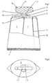
- the two-chamber container shown in Fig. 1 in the form of a single-use packaging for two to be kept separate but to be used together Components has an inner chamber 1 and an outer chamber 2 enveloping them, a head piece 3 and one only after filling the chambers 1 and 2 with different filling components generated closure seam 4 on the Head 3 opposite end of chambers 1, 2 separating them, closes.
- the head piece 3 has a shoulder 5 which, according to FIG. 2, has a round cross section flattened on the side, which can also be rounded in a circular or oval manner.
- the head piece 3 also has a - here central - neck 6, in which two channels 7 1 , 7 2 are made, one of which is connected to one of the chambers 1 and 2, respectively.
- the neck 6 is followed by a closure 8, which in the exemplary embodiment is designed as a twist-off closure 9.
- a predetermined breaking point 10 is carried out all or part of the way around the neck 6.
- the twist-off closure 9 is preferably designed such that when it is actuated and thereby exposes the openings of the channels 7 1 , 7 2 , it remains connected to the head piece 3, that is to say it does not have to be disposed of separately.
- the chamber 1 is made from a film tube 11 with a smaller diameter and the outer enveloping chamber 2 from a film tube 12 with a larger diameter.
- the film tube 11 is, as can be clearly seen from FIGS. 1 and 2, with a part of its wall attached to the centrally arranged intermediate piece 13, in which the channels 7 1 , 7 2 are made, separating them from each other such that each chamber 1 , 2 is only connected to a channel 7 1 or 7 2 .
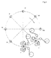
- Fig. 3 are the workstations for producing a two-chamber container, as he described above, for example.
- the winding takes place Foil around an inner mandrel and welding the foil into a tube Production of the inner chamber 1.
- a film is wrapped around an outer mandrel and welding it into a hose by making one Side weld to produce the outer chamber 2.
- the inner film tube and at station I the outer film tube become. If necessary, this can also be done with a height offset, in which case at least both hoses must be transferred to one level.
- At station III there will be a Portion of material, e.g. B. plasticized by heat, plastic one Mold cavity fed.
- the joint introduction of the Inner mandrel and the outer dome with the inner or outer hose produced in a mold cavity where the head piece is molded from the portion of material and at the same time connected to the two hose ends lying in approximately one plane becomes.
- the stations V to VII can all or in part as cooling stations for Hardening and cooling of the head piece may be provided.
- the The mold is opened and the finished product is removed from the mold and removed.
- the one described Allocation of the manufacturing steps to the stations can be seen as an example. Any other distribution of the work steps is also possible.
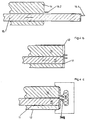
- FIG. 4 An outer mandrel 14 is shown in FIG. 4, in which an inner mandrel 15 is arranged so that it can be pushed in and out.
- the outer shape of the outer dome 14 corresponds to the inner shape of the outer chamber 2 and that of the inner mandrel 15 that of the inner chamber 1 (see also FIG. 5).
- the inner mandrel 15 and the outer mandrel 14 have cylindrical mandrel projections 16 1 , 16 2 , which are provided in the head piece 3 to be molded in order to form the channels 7 1 , 7 2 (see FIG. 1).
- a film strip or a section thereof is wound around the extended inner mandrel 15 to form a tube, which is closed by a side seam 17, preferably by welding becomes.
- the side seam 17 can be produced as an overlap seam or - as shown - as a parallel seam, the beginning and end of the film wrapping around the mandrel being aligned parallel to one another and then by means of e.g. B. a supplied welding gun is welded together.
- the outer mandrel has a depression which serves to receive the approximately radially projecting side seam 17 when the inner mandrel 15 is pulled back into the outer mandrel 14 (see FIG. 4b).
- both the inner mandrel 15 and the outer mandrel 14 provided with a side seam carry film tubes 11, 12 which project slightly over the free ends of the respective mandrels 14 and 15, respectively.
- the domes 14, 15 thus equipped with film tubes 11, 12 are fed with their free ends together into a mold cavity 18 which reproduces the external shape of a head piece 3 to be molded with a closure 8.
- the head piece 3 is formed by pressing the portion of material.
- the channel of the outer chamber 2 7 2 are formed.
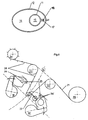
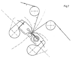
- FIG. 6 and 7 schematically illustrate the manufacture of a hose.
- the manufacturing process shown is particularly suitable for films with low strength, e.g. B. of 75 microns (0.075 mm).
- films with low strength e.g. B. of 75 microns (0.075 mm).
- Such on a roll 20 arranged film strip 21 is over two rotatable fixed deflection rollers 22, 23 out and wound with their beginning on a spool 24.
- Between the two Deflection rollers 22, 23 is a, for. B. arranged on a turntable, mandrel 14 and 15th insertable in such a way that it deflects the film strip 21 (see FIG. 6) and partly from it is enveloped.
- each welding jaw 19, 19 ' has divided, i.e. H. provided with a gap 25 Jaw projections 26.
- the shape of the jaw projections 26 is chosen so that the Foil tape 21 completely envelops the respective mandrel 14 and 15 and with two Side edges are parallel to each other, which protrude perpendicular to the mandrel surface.
- the welding takes place through the opposing welding jaws 19, 19 ' and forming a side seam 17 'of the adjacent side edges of the Foil tape 21.
- the welding jaws are in the pivoted-in state 19, 19 'the holder for the knife 27 in a guide in one of the welding jaws 19, 19 'insertable and in and in the gap 25 of both welding jaws 19, 19' movable, the previously welded side seam 17 ', as described above, is divided.
- the corresponding welding devices and foil stirring can Manufacture of the inner tube or the outer tube at different heights arranged, adjustable in height and / or optionally also axially movable or be pivoted away.
- a thicker, thicker film can also Wrap around a mandrel, with an overlap seam (not shown) can be provided that glued z. B. by applying an adhesive or a double-sided adhesive tape or welded, for which purpose suitable feeding and gluing or welding devices and, if appropriate, also Cutting devices should be provided, all of which are familiar to a person skilled in the art, so that they are not described in more detail here.
Description
- Fig. 1
- einen Zweikammerbehälter in Seitenansicht;
- Fig. 2
- den in Fig. 1 dargestellten Zweikammerbehälter in Draufsicht von oben;
- Fig. 3
- eine Vorrichtung zur Herstellung des Zweikammerbehälters in schematischer Darstellung;
- Fig. 4a, b, c
- ein Dornsystem und sein Zusammenwirken mit einem Preßwerkzeug;
- Fig. 5
- eine Ansicht von oben auf das Domsystem mit Schläuchen;
- Fig. 6
- die Zuführung eines Folienbandes um einen Dorn zur Herstellung einer Seitennaht;
- Fig. 7
- die Bildung einer Seitennaht an einer um einen Dorn gewickelten Folie und deren Abtrennung vom Folienband.
Claims (2)
- Vorrichtung zur Herstellung von Zweikammerbehältern mit einem Innendorn (15) und einem Außendorn (14) mit größerem Durchmesser, wobei der innendorn (15) im Außendorn (14) ein- und ausfahrbar angeordnet ist, einem Formhohlraum (18) für ein Kopfstück (3) und einem Materialgeber zur Zufuhr einer erwärmten Materialportion eines thermoplastischen Kunststoffes in den Formhohlraum (18) einer Pressform,
dadurch gekennzeichnet, daß sie eine Einrichtung zum Aufwickeln einer Folie um den ausgefahrenen Innendorn (15) und eine Einrichtung zum Aufwickeln einer Folie um den Außendorn (14) sowie zustellbare Schweißeinrichtungen (19) zur Herstellung von Seitenlängsnähten (17) zur Herstellung von Schläuchen (11, 12) aufweist, wobei die Dorne (14, 15) gemeinsam in den Formhohlraum (18) der Preßform zur Herstellung des Kopfstücks (3) mit Verschluß (8) und zur Verbindung mit den Wandungen der gebildeten Kammern (1, 2) ein- und ausführbar sind, und daß jeder Dorn (14, 15) in Richtung des Formhohlraums (18) einen Vorsprung (161, 162) zur Bildung eines mit je einer Kammer (1 bzw. 2) verbundenen Kanals (71 bzw. 72) im Kopfstück (3) aufweist. - Vorrichtung nach Anspruch 1,
dadurch gekennzeichnet, daß die zustellbare Schweißeinrichtung zwei sich gegenüberliegende verschwenkbare Schweißbacken (19, 19') aufweist, die jeweils zwei durch einen Spalt (25) geteilte Backenvorsprünge (26, 26') aufweisen, wobei in den gemeinsamen Spalt (25) eine Schneidvorrichtung (27) ein- und ausführbar ist.
Applications Claiming Priority (3)
| Application Number | Priority Date | Filing Date | Title |
|---|---|---|---|
| DE19958920A DE19958920C2 (de) | 1999-12-07 | 1999-12-07 | Zweikammerbehälter |
| DE19958920 | 1999-12-07 | ||
| PCT/EP2000/012214 WO2001042091A2 (de) | 1999-12-07 | 2000-12-05 | Zweikammerbehälter |
Publications (2)
| Publication Number | Publication Date |
|---|---|
| EP1237794A2 EP1237794A2 (de) | 2002-09-11 |
| EP1237794B1 true EP1237794B1 (de) | 2003-08-27 |
Family
ID=7931689
Family Applications (1)
| Application Number | Title | Priority Date | Filing Date |
|---|---|---|---|
| EP00991144A Expired - Lifetime EP1237794B1 (de) | 1999-12-07 | 2000-12-05 | Vorrichtung zur Herstellung von Zweikammerbehältern |
Country Status (19)
| Country | Link |
|---|---|
| US (1) | US6905323B2 (de) |
| EP (1) | EP1237794B1 (de) |
| JP (1) | JP2003516283A (de) |
| KR (1) | KR20020071879A (de) |
| CN (1) | CN1196629C (de) |
| AT (1) | ATE248107T1 (de) |
| AU (1) | AU771401B2 (de) |
| BG (1) | BG64207B1 (de) |
| BR (1) | BR0016221A (de) |
| DE (2) | DE19958920C2 (de) |
| DK (1) | DK1237794T3 (de) |
| ES (1) | ES2206350T3 (de) |
| HK (1) | HK1054534A1 (de) |
| HU (1) | HU226264B1 (de) |
| MX (1) | MXPA02005684A (de) |
| PL (1) | PL201957B1 (de) |
| PT (1) | PT1237794E (de) |
| RU (1) | RU2246403C2 (de) |
| WO (1) | WO2001042091A2 (de) |
Families Citing this family (19)
| Publication number | Priority date | Publication date | Assignee | Title |
|---|---|---|---|---|
| EP1245500A1 (de) * | 2001-03-15 | 2002-10-02 | The Procter & Gamble Company | Mehrkammerbeutel mit mehreren Auslasskanälen |
| US7048141B2 (en) * | 2002-05-14 | 2006-05-23 | Antioch Holdings, Inc. | Personal medication dispenser |
| DE10304500A1 (de) | 2003-02-05 | 2004-08-26 | Bernd Hansen | Behälter |
| AU2004100000A4 (en) | 2004-01-02 | 2004-02-12 | Sands Innovations Pty Ltd | Dispensing stirring implement |
| US7044333B2 (en) | 2004-01-22 | 2006-05-16 | Church & Dwight Co., Inc. | Toothpaste tube |
| EP1676784A1 (de) * | 2004-12-29 | 2006-07-05 | The Procter & Gamble Company | Flexibler Flüssigkeitsbehälter, Verfahren zur Herstellung eines flüssigkeitsgefüllten Behälters |
| WO2006127189A2 (en) * | 2005-05-24 | 2006-11-30 | Conagra Foods, Inc. | Flavor gradient container and packaged liquid-based food item |
| US7325703B2 (en) * | 2005-06-16 | 2008-02-05 | R.P. Scherer Technologies, Inc. | Multi-cavity blister package for storing and dispensing flowable substances |
| CN101600633A (zh) | 2007-01-31 | 2009-12-09 | 桑德斯创新有限公司 | 分发器具及其制造方法 |
| DE102008004088A1 (de) * | 2008-01-12 | 2009-07-16 | Bernd Hansen | Verfahren und Vorrichtung zum Herstellen von Behältern aus thermoplastischem Kunststoff sowie derart hergestellter Behälter |
| AU2008365185B2 (en) | 2008-12-09 | 2016-05-05 | Sands Innovations Pty Ltd | A dispensing container |
| US8413845B1 (en) | 2009-07-20 | 2013-04-09 | Thomas J. Duncan | Dual-compartment dispensing container |
| USD636890S1 (en) | 2009-09-17 | 2011-04-26 | Sands Innovations Pty. Ltd. | Dispensing utensil |
| US8511500B2 (en) | 2010-06-07 | 2013-08-20 | Sands Innovations Pty. Ltd. | Dispensing container |
| DE102010031734A1 (de) * | 2010-07-21 | 2012-01-26 | Multivac Sepp Haggenmüller Gmbh & Co. Kg | Verpackung für ein flüssiges, pulvriges oder pastöses Produkt |
| US8485360B2 (en) | 2011-03-04 | 2013-07-16 | Sands Innovations Pty, Ltd. | Fracturable container |
| US9045274B2 (en) | 2011-08-30 | 2015-06-02 | Reinhard Matye | Multi-chamber container for bulk materials, and method of filling a multi-chamber container |
| EP3546122B1 (de) | 2018-03-30 | 2020-10-21 | Essilor International | Linsenhalteblock und verfahren zum sperren und entsperren einer optischen linsenkomponente |
| CN117141053B (zh) * | 2023-10-27 | 2024-01-05 | 湖南大道新材料有限公司 | 一种双子袋生产设备 |
Family Cites Families (20)
| Publication number | Priority date | Publication date | Assignee | Title |
|---|---|---|---|---|
| US2661870A (en) * | 1948-09-28 | 1953-12-08 | Alfred G Huenergardt | Multiple liquid dispensing container |
| FR1209359A (fr) | 1958-07-31 | 1960-03-01 | Tuboplast France | Récipient automélangeur compartimenté |
| US3260777A (en) * | 1962-12-07 | 1966-07-12 | American Can Co | Method of making a collapsible container structure |
| US3157096A (en) * | 1962-12-27 | 1964-11-17 | Rissen Gmbh Maschf | Device adapted to be used in the production of conical paper cups |
| DE1910032A1 (de) * | 1969-02-27 | 1970-09-10 | Wallace & Tiernan Chemi Gmbh | Vorrichtung zur dosierten Entnahme mindestens zweier Komponenten einer haertbaren Masse in einem bestimmten Mengenverhaeltnis |
| US3991294A (en) * | 1973-11-13 | 1976-11-09 | The Procter & Gamble Company | Apparatus for making longitudinally partitioned tubular bodies and container assemblies |
| US4267005A (en) * | 1979-04-30 | 1981-05-12 | Barnaby Roland E | Heat sealing apparatus |
| US4285750A (en) * | 1979-07-23 | 1981-08-25 | Owens-Illinois, Inc. | Method for producing a plastic sleeve |
| US4630429A (en) * | 1985-02-01 | 1986-12-23 | Baxter Travenol Laboratories, Inc. | Apparatus and method for sealing a web of film in a form, fill, and seal packaging system |
| US4757668A (en) * | 1986-01-27 | 1988-07-19 | Ilapak Research & Development S.A. | Method and apparatus for form-fill-seal packaging of articles |
| JPS62139968U (de) * | 1986-02-26 | 1987-09-03 | ||
| FR2623170B1 (fr) | 1987-11-12 | 1995-05-19 | Tartaglione Andre | Procede de realisation d'un contenant plastique avec dispositif de bouchage et contenant plastique obtenu par ce procede |
| US5219373A (en) * | 1989-07-26 | 1993-06-15 | Yoshida Industry Co., Ltd. | Method of fabricating tube container |
| DE4009661C1 (de) * | 1990-03-26 | 1991-03-07 | Aisa Automation Industrielle S.A., Vouvry, Ch | |
| GB9523266D0 (en) | 1995-11-14 | 1996-01-17 | Courtaulds Packaging Ltd | A two-compartment container |
| DE19640833C1 (de) * | 1996-10-02 | 1997-12-18 | Automation Industrielle Sa | Vorrichtung zur Herstellung von Zwei- oder Mehrkammertuben |
| US5899361A (en) * | 1997-06-10 | 1999-05-04 | Owens-Illinois Closure Inc. | Hinged closure for a dual chamber dispensing package |
| FR2768705B1 (fr) | 1997-09-24 | 1999-11-19 | Oreal | Conditionnement pour un produit a trois composantes |
| US6210621B1 (en) * | 1998-12-04 | 2001-04-03 | Enamelon, Inc. | Method for making plural chambered dispensing tubes |
| DE19911729B4 (de) * | 1999-03-16 | 2007-01-11 | Aisa Automation Industrielle S.A. | Verfahren und Vorrichtung zur Herstellung einer Zweikammertube |
-
1999
- 1999-12-07 DE DE19958920A patent/DE19958920C2/de not_active Expired - Fee Related
-
2000
- 2000-12-05 PT PT00991144T patent/PT1237794E/pt unknown
- 2000-12-05 JP JP2001543402A patent/JP2003516283A/ja not_active Ceased
- 2000-12-05 HU HU0204164A patent/HU226264B1/hu not_active IP Right Cessation
- 2000-12-05 DK DK00991144T patent/DK1237794T3/da active
- 2000-12-05 DE DE50003486T patent/DE50003486D1/de not_active Expired - Lifetime
- 2000-12-05 EP EP00991144A patent/EP1237794B1/de not_active Expired - Lifetime
- 2000-12-05 US US10/149,369 patent/US6905323B2/en not_active Expired - Fee Related
- 2000-12-05 PL PL355719A patent/PL201957B1/pl not_active IP Right Cessation
- 2000-12-05 MX MXPA02005684A patent/MXPA02005684A/es active IP Right Grant
- 2000-12-05 AT AT00991144T patent/ATE248107T1/de not_active IP Right Cessation
- 2000-12-05 WO PCT/EP2000/012214 patent/WO2001042091A2/de active Search and Examination
- 2000-12-05 BR BR0016221-3A patent/BR0016221A/pt active Pending
- 2000-12-05 AU AU31556/01A patent/AU771401B2/en not_active Ceased
- 2000-12-05 KR KR1020027007225A patent/KR20020071879A/ko not_active Application Discontinuation
- 2000-12-05 RU RU2002118106/12A patent/RU2246403C2/ru not_active IP Right Cessation
- 2000-12-05 CN CNB008168148A patent/CN1196629C/zh not_active Expired - Fee Related
- 2000-12-05 ES ES00991144T patent/ES2206350T3/es not_active Expired - Lifetime
-
2002
- 2002-06-07 BG BG106794A patent/BG64207B1/bg unknown
-
2003
- 2003-09-25 HK HK03106886A patent/HK1054534A1/xx not_active IP Right Cessation
Also Published As
| Publication number | Publication date |
|---|---|
| HUP0204164A2 (en) | 2003-03-28 |
| BG64207B1 (bg) | 2004-05-31 |
| CN1407936A (zh) | 2003-04-02 |
| HU226264B1 (en) | 2008-07-28 |
| WO2001042091A2 (de) | 2001-06-14 |
| JP2003516283A (ja) | 2003-05-13 |
| ATE248107T1 (de) | 2003-09-15 |
| WO2001042091A3 (de) | 2001-11-01 |
| BR0016221A (pt) | 2002-09-10 |
| US6905323B2 (en) | 2005-06-14 |
| DK1237794T3 (da) | 2003-12-22 |
| RU2246403C2 (ru) | 2005-02-20 |
| MXPA02005684A (es) | 2004-01-29 |
| AU3155601A (en) | 2001-06-18 |
| BG106794A (en) | 2003-01-31 |
| PL355719A1 (en) | 2004-05-17 |
| AU771401B2 (en) | 2004-03-18 |
| PL201957B1 (pl) | 2009-05-29 |
| CN1196629C (zh) | 2005-04-13 |
| ES2206350T3 (es) | 2004-05-16 |
| EP1237794A2 (de) | 2002-09-11 |
| DE50003486D1 (de) | 2003-10-02 |
| DE19958920C2 (de) | 2003-03-20 |
| PT1237794E (pt) | 2003-12-31 |
| KR20020071879A (ko) | 2002-09-13 |
| HK1054534A1 (en) | 2003-12-05 |
| US20030222099A1 (en) | 2003-12-04 |
| DE19958920A1 (de) | 2001-06-21 |
Similar Documents
| Publication | Publication Date | Title |
|---|---|---|
| EP1237794B1 (de) | Vorrichtung zur Herstellung von Zweikammerbehältern | |
| DE3043134C2 (de) | Packung für fließfähige Füllgüter | |
| DE3217156C2 (de) | ||
| EP0473769B1 (de) | Vorrichtung zur herstellung von tuben | |
| EP1183144B1 (de) | Verfahren zum herstellen von extrusionsblasgeformten behältern mit mindestens zwei kammern | |
| DE2759138C3 (de) | Verfahren und Vorrichtung zur Herstellung von insbesondere zylinderformigen Behältern | |
| DE1479542B2 (de) | Verfahren und vorrichtung zum herstellen hohler gegenstaende aus thermoplastischem kunststoff durch blasen eines plastischen vorformlings | |
| DD151897A5 (de) | Verfahren zur herstellung eines formkoerpers aus kunststoff | |
| DE3231859A1 (de) | Behaelter aus thermoplastischem material sowie verfahren und einrichtung zur herstellung desselben | |
| DE1299406B (de) | Verfahren und Vorrichtung zum Herstellen von Flaschen u. dgl. Hohl-koerpern aus warmformbaren Kunststoffen | |
| EP0867374B1 (de) | Verfahren zur Herstellung einer Mehrkammer-Verpackungstube | |
| EP1163108B1 (de) | Verfahren und vorrichtung zur herstellung einer zweikammertube | |
| EP0955152B1 (de) | Verfahren zur Herstellung einer Mehrkammer-Verpackungstube | |
| DE3929664A1 (de) | Verfahren und vorrichtung zur herstellung von behaeltern mit einem anschlusselement, wie zum beispiel einem fuell- und/oder entnahmestutzen | |
| DE112005001655B4 (de) | Form-, Füll- und Versiegelungs-Verpackungsmaschine, eine Di- rektspritzgießstation und ein Gießwerkzeugsatz | |
| DE19935139C2 (de) | Verfahren und Vorrichtung zum Herstellen eines Kunststoffkörpers | |
| DE1479216B2 (de) | ||
| DE19652036C2 (de) | Verfahren zum Herstellen von Zuschnitten für hinterspritzte oder hinterpreßte Kunststoffteile | |
| DE2850843A1 (de) | Verfahren und vorrichtung zum herstellen von ringsum mit einer banderole oder einem faltkarton verbundenen behaelter aus thermoplastischer kunststoffolie | |
| DE19940615C2 (de) | Verfahren und Vorrichtung zur Herstellung von Kartuschen für fließfähige Medien | |
| AT407725B (de) | Verfahren zur herstellung eines formkörpers aus kunststoff | |
| DE1629237B2 (de) | Verfahren zum herstellen von tragetaschen aus kunststoffolien | |
| WO2010108291A1 (de) | Verfahren und vorrichtung zur herstellung eines spritzgusshohlkörpers | |
| DE2521935A1 (de) | Verfahren und einrichtung zur herstellung von laminierten hohlkoerpern, sowie nach dem verfahren hergestellter hohlkoerper | |
| DE1256053B (de) | Verfahren und Vorrichtung zum Herstellen einlagiger Hohlkoerper aus Papier- oder Folienmaterial |
Legal Events
| Date | Code | Title | Description |
|---|---|---|---|
| PUAI | Public reference made under article 153(3) epc to a published international application that has entered the european phase |
Free format text: ORIGINAL CODE: 0009012 |
|
| 17P | Request for examination filed |
Effective date: 20020701 |
|
| AK | Designated contracting states |
Kind code of ref document: A2 Designated state(s): AT BE CH CY DE DK ES FI FR GB GR IE IT LI LU MC NL PT SE TR |
|
| AX | Request for extension of the european patent |
Free format text: AL;LT;LV;MK;RO;SI |
|
| RTI1 | Title (correction) |
Free format text: APPARATUS FOR MANUFACTURING TWIN-CHAMBERED CONTAINERS |
|
| GRAH | Despatch of communication of intention to grant a patent |
Free format text: ORIGINAL CODE: EPIDOS IGRA |
|
| GRAH | Despatch of communication of intention to grant a patent |
Free format text: ORIGINAL CODE: EPIDOS IGRA |
|
| GRAA | (expected) grant |
Free format text: ORIGINAL CODE: 0009210 |
|
| AK | Designated contracting states |
Designated state(s): AT BE CH CY DE DK ES FI FR GB GR IE IT LI LU MC NL PT SE TR |
|
| PG25 | Lapsed in a contracting state [announced via postgrant information from national office to epo] |
Ref country code: FI Free format text: LAPSE BECAUSE OF FAILURE TO SUBMIT A TRANSLATION OF THE DESCRIPTION OR TO PAY THE FEE WITHIN THE PRESCRIBED TIME-LIMIT Effective date: 20030827 |
|
| REG | Reference to a national code |
Ref country code: GB Ref legal event code: FG4D Free format text: NOT ENGLISH |
|
| REG | Reference to a national code |
Ref country code: CH Ref legal event code: EP |
|
| REG | Reference to a national code |
Ref country code: IE Ref legal event code: FG4D Free format text: GERMAN |
|
| REF | Corresponds to: |
Ref document number: 50003486 Country of ref document: DE Date of ref document: 20031002 Kind code of ref document: P |
|
| REG | Reference to a national code |
Ref country code: CH Ref legal event code: NV Representative=s name: BRAUN & PARTNER PATENT-, MARKEN-, RECHTSANWAELTE |
|
| PG25 | Lapsed in a contracting state [announced via postgrant information from national office to epo] |
Ref country code: CY Free format text: LAPSE BECAUSE OF FAILURE TO SUBMIT A TRANSLATION OF THE DESCRIPTION OR TO PAY THE FEE WITHIN THE PRESCRIBED TIME-LIMIT Effective date: 20031205 |
|
| GBT | Gb: translation of ep patent filed (gb section 77(6)(a)/1977) |
Effective date: 20031119 |
|
| REG | Reference to a national code |
Ref country code: SE Ref legal event code: TRGR |
|
| REG | Reference to a national code |
Ref country code: GR Ref legal event code: EP Ref document number: 20030404625 Country of ref document: GR Ref country code: DK Ref legal event code: T3 |
|
| PG25 | Lapsed in a contracting state [announced via postgrant information from national office to epo] |
Ref country code: MC Free format text: LAPSE BECAUSE OF NON-PAYMENT OF DUE FEES Effective date: 20031231 |
|
| LTIE | Lt: invalidation of european patent or patent extension |
Effective date: 20030827 |
|
| REG | Reference to a national code |
Ref country code: ES Ref legal event code: FG2A Ref document number: 2206350 Country of ref document: ES Kind code of ref document: T3 |
|
| ET | Fr: translation filed | ||
| PLBE | No opposition filed within time limit |
Free format text: ORIGINAL CODE: 0009261 |
|
| STAA | Information on the status of an ep patent application or granted ep patent |
Free format text: STATUS: NO OPPOSITION FILED WITHIN TIME LIMIT |
|
| 26N | No opposition filed |
Effective date: 20040528 |
|
| PGFP | Annual fee paid to national office [announced via postgrant information from national office to epo] |
Ref country code: DK Payment date: 20071220 Year of fee payment: 8 Ref country code: ES Payment date: 20071220 Year of fee payment: 8 Ref country code: LU Payment date: 20071219 Year of fee payment: 8 Ref country code: NL Payment date: 20071213 Year of fee payment: 8 |
|
| PGFP | Annual fee paid to national office [announced via postgrant information from national office to epo] |
Ref country code: IT Payment date: 20071222 Year of fee payment: 8 Ref country code: AT Payment date: 20071220 Year of fee payment: 8 |
|
| PGFP | Annual fee paid to national office [announced via postgrant information from national office to epo] |
Ref country code: BE Payment date: 20071219 Year of fee payment: 8 Ref country code: SE Payment date: 20071220 Year of fee payment: 8 |
|
| PGFP | Annual fee paid to national office [announced via postgrant information from national office to epo] |
Ref country code: GR Payment date: 20071219 Year of fee payment: 8 Ref country code: PT Payment date: 20071129 Year of fee payment: 8 |
|
| PGFP | Annual fee paid to national office [announced via postgrant information from national office to epo] |
Ref country code: TR Payment date: 20071123 Year of fee payment: 8 |
|
| REG | Reference to a national code |
Ref country code: PT Ref legal event code: MM4A Free format text: LAPSE DUE TO NON-PAYMENT OF FEES Effective date: 20090605 |
|
| BERE | Be: lapsed |
Owner name: S.A. AUTOMATION INDUSTRIELLE *AISA Effective date: 20081231 |
|
| REG | Reference to a national code |
Ref country code: DK Ref legal event code: EBP |
|
| EUG | Se: european patent has lapsed | ||
| PG25 | Lapsed in a contracting state [announced via postgrant information from national office to epo] |
Ref country code: AT Free format text: LAPSE BECAUSE OF NON-PAYMENT OF DUE FEES Effective date: 20081205 Ref country code: PT Free format text: LAPSE BECAUSE OF NON-PAYMENT OF DUE FEES Effective date: 20090605 |
|
| PGFP | Annual fee paid to national office [announced via postgrant information from national office to epo] |
Ref country code: IE Payment date: 20071214 Year of fee payment: 8 |
|
| NLV4 | Nl: lapsed or anulled due to non-payment of the annual fee |
Effective date: 20090701 |
|
| REG | Reference to a national code |
Ref country code: IE Ref legal event code: MM4A |
|
| PG25 | Lapsed in a contracting state [announced via postgrant information from national office to epo] |
Ref country code: BE Free format text: LAPSE BECAUSE OF NON-PAYMENT OF DUE FEES Effective date: 20081231 |
|
| PG25 | Lapsed in a contracting state [announced via postgrant information from national office to epo] |
Ref country code: IE Free format text: LAPSE BECAUSE OF NON-PAYMENT OF DUE FEES Effective date: 20081205 |
|
| PG25 | Lapsed in a contracting state [announced via postgrant information from national office to epo] |
Ref country code: NL Free format text: LAPSE BECAUSE OF NON-PAYMENT OF DUE FEES Effective date: 20090701 |
|
| PG25 | Lapsed in a contracting state [announced via postgrant information from national office to epo] |
Ref country code: DK Free format text: LAPSE BECAUSE OF NON-PAYMENT OF DUE FEES Effective date: 20090105 |
|
| PGFP | Annual fee paid to national office [announced via postgrant information from national office to epo] |
Ref country code: CH Payment date: 20091222 Year of fee payment: 10 |
|
| PG25 | Lapsed in a contracting state [announced via postgrant information from national office to epo] |
Ref country code: GR Free format text: LAPSE BECAUSE OF NON-PAYMENT OF DUE FEES Effective date: 20090703 |
|
| REG | Reference to a national code |
Ref country code: ES Ref legal event code: FD2A Effective date: 20081209 |
|
| PG25 | Lapsed in a contracting state [announced via postgrant information from national office to epo] |
Ref country code: ES Free format text: LAPSE BECAUSE OF NON-PAYMENT OF DUE FEES Effective date: 20081209 |
|
| PGFP | Annual fee paid to national office [announced via postgrant information from national office to epo] |
Ref country code: GB Payment date: 20091221 Year of fee payment: 10 Ref country code: FR Payment date: 20100105 Year of fee payment: 10 |
|
| PGFP | Annual fee paid to national office [announced via postgrant information from national office to epo] |
Ref country code: DE Payment date: 20100222 Year of fee payment: 10 |
|
| PG25 | Lapsed in a contracting state [announced via postgrant information from national office to epo] |
Ref country code: SE Free format text: LAPSE BECAUSE OF NON-PAYMENT OF DUE FEES Effective date: 20081206 Ref country code: LU Free format text: LAPSE BECAUSE OF NON-PAYMENT OF DUE FEES Effective date: 20081205 |
|
| REG | Reference to a national code |
Ref country code: CH Ref legal event code: PL |
|
| GBPC | Gb: european patent ceased through non-payment of renewal fee |
Effective date: 20101205 |
|
| REG | Reference to a national code |
Ref country code: FR Ref legal event code: ST Effective date: 20110831 |
|
| PG25 | Lapsed in a contracting state [announced via postgrant information from national office to epo] |
Ref country code: TR Free format text: LAPSE BECAUSE OF NON-PAYMENT OF DUE FEES Effective date: 20100928 |
|
| PG25 | Lapsed in a contracting state [announced via postgrant information from national office to epo] |
Ref country code: FR Free format text: LAPSE BECAUSE OF NON-PAYMENT OF DUE FEES Effective date: 20110103 Ref country code: LI Free format text: LAPSE BECAUSE OF NON-PAYMENT OF DUE FEES Effective date: 20101231 Ref country code: CH Free format text: LAPSE BECAUSE OF NON-PAYMENT OF DUE FEES Effective date: 20101231 |
|
| REG | Reference to a national code |
Ref country code: DE Ref legal event code: R119 Ref document number: 50003486 Country of ref document: DE Effective date: 20110701 |
|
| PG25 | Lapsed in a contracting state [announced via postgrant information from national office to epo] |
Ref country code: DE Free format text: LAPSE BECAUSE OF NON-PAYMENT OF DUE FEES Effective date: 20110701 Ref country code: GB Free format text: LAPSE BECAUSE OF NON-PAYMENT OF DUE FEES Effective date: 20101205 |
|
| PG25 | Lapsed in a contracting state [announced via postgrant information from national office to epo] |
Ref country code: TR Free format text: LAPSE BECAUSE OF NON-PAYMENT OF DUE FEES Effective date: 20081205 |
|
| PG25 | Lapsed in a contracting state [announced via postgrant information from national office to epo] |
Ref country code: IT Free format text: LAPSE BECAUSE OF NON-PAYMENT OF DUE FEES Effective date: 20081205 |