EP1238577A1 - Device for coupling an implement to a vehicle - Google Patents
Device for coupling an implement to a vehicle Download PDFInfo
- Publication number
- EP1238577A1 EP1238577A1 EP02004793A EP02004793A EP1238577A1 EP 1238577 A1 EP1238577 A1 EP 1238577A1 EP 02004793 A EP02004793 A EP 02004793A EP 02004793 A EP02004793 A EP 02004793A EP 1238577 A1 EP1238577 A1 EP 1238577A1
- Authority
- EP
- European Patent Office
- Prior art keywords
- coupling
- vehicle
- coupling elements
- sensors
- elements
- Prior art date
- Legal status (The legal status is an assumption and is not a legal conclusion. Google has not performed a legal analysis and makes no representation as to the accuracy of the status listed.)
- Granted
Links
Images


Classifications
-
- B—PERFORMING OPERATIONS; TRANSPORTING
- B60—VEHICLES IN GENERAL
- B60D—VEHICLE CONNECTIONS
- B60D1/00—Traction couplings; Hitches; Draw-gear; Towing devices
- B60D1/24—Traction couplings; Hitches; Draw-gear; Towing devices characterised by arrangements for particular functions
- B60D1/36—Traction couplings; Hitches; Draw-gear; Towing devices characterised by arrangements for particular functions for facilitating connection, e.g. hitch catchers, visual guide means, signalling aids
-
- A—HUMAN NECESSITIES
- A01—AGRICULTURE; FORESTRY; ANIMAL HUSBANDRY; HUNTING; TRAPPING; FISHING
- A01B—SOIL WORKING IN AGRICULTURE OR FORESTRY; PARTS, DETAILS, OR ACCESSORIES OF AGRICULTURAL MACHINES OR IMPLEMENTS, IN GENERAL
- A01B59/00—Devices specially adapted for connection between animals or tractors and agricultural machines or implements
- A01B59/06—Devices specially adapted for connection between animals or tractors and agricultural machines or implements for machines mounted on tractors
- A01B59/066—Devices specially adapted for connection between animals or tractors and agricultural machines or implements for machines mounted on tractors of the type comprising at least two lower arms and one upper arm generally arranged in a triangle (e.g. three-point hitches)
- A01B59/068—Devices specially adapted for connection between animals or tractors and agricultural machines or implements for machines mounted on tractors of the type comprising at least two lower arms and one upper arm generally arranged in a triangle (e.g. three-point hitches) the lower arms being lifted or lowered by power actuator means provided externally on the tractor
-
- B—PERFORMING OPERATIONS; TRANSPORTING
- B60—VEHICLES IN GENERAL
- B60D—VEHICLE CONNECTIONS
- B60D1/00—Traction couplings; Hitches; Draw-gear; Towing devices
- B60D2001/001—Traction couplings; Hitches; Draw-gear; Towing devices specially adapted for use on vehicles other than cars
- B60D2001/008—Traction couplings; Hitches; Draw-gear; Towing devices specially adapted for use on vehicles other than cars specially adapted for implements, e.g. towed tools
Definitions
- the invention relates to a device for coupling a Device to a work vehicle, especially one agricultural or industrial vehicle, with a Device interface, the vehicle-side coupling elements and has corresponding device-side coupling elements.
- a Device interface the vehicle-side coupling elements and has corresponding device-side coupling elements.
- too Device coupling devices known, known by the for example, agricultural implements on agricultural vehicle, such as agricultural tractors or Harvester, can be fastened.
- vehicle-side coupling elements are often not rigid with the Vehicle connected but can be relative to the vehicle move so that the attachment is also relative to the vehicle can move.
- a large number of coupling elements are Fastening options known, for example as a hook trained coupling points or coupling plates areal coupling areas.
- US-A-3,432,184 describes an attachment for one Tractor with a triangular coupling plate that over several hydraulic and electrical actuators with the Tractor frame is connected and by pressing the Actuators relative to the vehicle frame within one given movement space translational and rotational can move.
- the attachment also contains one triangular mounting plate, the upper edges of which are flange-like are bent so that they match the corresponding edges of the Can accommodate coupling plate.
- the well-known attachment is designed for a simple and quick attachment of attachments from from the vehicle cabin without first having an exact Alignment of the tractor to the implement must be done. To for this purpose, the actuators can be Activate the control console in the vehicle cabin.
- the object underlying the invention is seen in to specify a coupling device of the type mentioned at the outset, by which the aforementioned problems are overcome.
- the operator should be relieved and the Pairing process can be facilitated and accelerated, leading to time and Leads to fuel savings.
- the coupling device contains a Device interface, the vehicle-side coupling elements and has corresponding device-side coupling elements.
- the spatial position of the adjustment means Vehicle coupling elements relative to the work vehicle to adjust.
- the invention at least suggests the use a sensor device, which determines the position of the device Coupling elements recognized or detected.
- An evaluation device determines the relative position of the coupling elements on the device side to the coupling elements on the vehicle.
- a control device calculates a trajectory for the coupling process and controls the setting means based on a start signal indicates that the coupling process along the calculated Movement path is executed fully automatically.
- the work machine To make a device coupling, the work machine first moved close to the attachment.
- the Approach of the work vehicle to the device is by a Sensor device and an evaluation device the location of the device-side coupling elements relative to a predetermined Point on the machine or on the location of the device-side coupling elements continuously or periodically recorded within predefined time intervals. Doing so the measured values obtained by the sensor device associated coordinates of the coupling elements on the device side calculated and it is continuously checked whether the device-side coupling elements in the range of motion (work area) of the vehicle-side coupling elements. Since the vehicle-side coupling elements by the setting means within a relatively large range of motion the driver has to align the work vehicle relative to the attachment a large margin and can Quickly approach the vehicle to the attachment.
- the vehicle was driven into a position in which the device-side coupling elements are located in the work area suitable information from the evaluation device, for example in the form of an acoustic or optical Signal, given to the operator.
- the Operator now brings the work vehicle to a stop and checks whether the coupling area is unobstructed and one safe automatic coupling can take place. Is this the Case, the operator activates, for example by Actuation of a push button switch, the automatic Coupling process.
- the control device calculates from the current relative position between the vehicle side and the device-side coupling elements a trajectory for the Coupling process and controls the setting means to the vehicle-side coupling elements automatically along the calculated movement path to the coupling elements on the device side to approach.
- the location the device-side crosspoints used as the target location does not change when the work vehicle and device are stationary.
- the actual position of the coupling points on the vehicle is by a suitable one which interacts with the setting means Sensors recognized or recorded.
- the coupling device according to the invention largely allows one automated coupling process between work vehicle and Attachment that has no special requirements for the Operator skill and experience.
- By providing an automatic coupling process the operator is relieved and can their Pay full attention to security aspects, For example, whether people are through the pairing process endangered or whether there are obstacles in the coupling area are located.
- the coupling process can be carried out quickly, because it runs automatically and not from skill depends on the operator. This leads to time and Fuel savings.
- the coupling elements on the vehicle are preferably on one Coupling frame arranged by variable length Setting means is connected to the vehicle.
- Adjustment means come, for example, on one or both sides acting hydraulic cylinders into consideration. However, it can also other hydraulic or electromechanical control elements be used.
- the coupling frame can be designed in many ways his. For example, it is essentially triangular Plate which is designed as a single-phase coupler and at the Key points attack the adjusting means, as is known from US-A-3,432,184 evident.
- the coupling frame can also have the shape of a have isosceles or equilateral triangular frames whose corner points on the one hand articulate the adjusting means attack and on the other hand coupling elements in the form of hooks and the like are attached, as from the post-published DE-A-199 51 840 emerges. It can act in the coupling frame also with a portal frame an upper horizontal bar and two lateral ones Vertical bar (US-A-5,092,409).
- a particularly preferred embodiment of the invention provides before that the coupling device at least six contains adjustable length adjustment means, the first of which End is articulated to the vehicle and their respective second end articulated with a coupling frame on which the Coupling elements are arranged, is connected.
- the Adjustment means are in closed kinematic chains arranged and allow the movement of the coupling frame in six degrees of freedom.
- Such an arrangement of Setting means goes from the subsequently published DE-A-199 51 840, the disclosure of which is hereby incorporated by reference. With this arrangement, the coupling elements or Crosspoints within wide limits within a large one Move the work space in six degrees of freedom and to adjust. This favors that even at gross Positioning the work vehicle an automatic coupling can be done.
- the setting means are preferably in the manner of a hexapod arranged.
- a hexapod arrangement is used, for example, in the described in DE-A-199 51 840.
- the Setting devices are equipped with displacement sensors, from whose The actual spatial position of the Coupling frame and thus also the actual locations of the Have coupling elements or coupling points determined. in this connection known calculation methods can be used (Hebsacker, M .: The interpretation of the kinematics of the hexaglide - Methodology for the design of parallel machine tools, VDI Reports No. 1427, 1998).
- Sensors for measuring the length of the adjustable Adjustment means provided. From the measured values of the sensors the coordinates of the coupling points of the hexapod cultivation to calculate.
- the sensors can, for example, in the Hydraulic cylinders of a hexapod arrangement can be integrated.
- a suitable method is used for position detection the image processing by which the signals of one or multiple cameras can be evaluated. For example, two Cameras side by side in the corner points of the Vehicle cabin roof mounted and on the device side Coupling structure aligned. The cameras take them Coupling structure in a fixed geometric arrangement on and recognize characteristic features of the measured Coupling structure. You transfer the digital images to one Control unit in which the pictures with the appropriate software processed to the coordinates of the device To calculate coupling elements or coupling points.
- Image processing methods are used in the evaluation, like automation in industrial Manufacturing technology for the position detection of a workpiece in Space.
- a known method first characteristic, optically prominent areas, for example corners or bores of a workpiece determined, which then with the help of a relaxation corresponding characteristic areas of a known Prototypes. You can then use the assignment The position of the entire workpiece can be determined.
- the two cameras also use parts of the Adjustment means, especially the Hexapod, added, see above that when processing the images, the coordinates of the coupling points on the device side relative to the hexapod attachment be determined. This allows the correction of errors that due to assembly tolerances when attaching the two cameras or by slight displacements of the cameras due to the Vehicle operation are caused.
- the Image processing method has the advantage that even then, if in the measurement a characteristic feature entirely or partially fails (e.g. if this characteristic is due to Components is covered), the location of the coupling points can still be clearly determined.
- Ultrasound sensors can be used as an alternative to magnetic sensors be used.
- Ultrasonic sensors consist of three components: a transmitter, a receiver and one electronic unit.
- the transmitter consists of three Ultrasound sensors, which are attached to the device in a triangular shape are. Corresponding to that is a small triangle of Ultrasound microphones attached to the work machine.
- the data of the microphones are in the control device Coordinates of the coupling points converted and to the Hexapod control transmitted. Since this is sound waves this system is vulnerable to strangers Sound sources.
- the Ultrasonic solutions offer cheap and sufficiently good ones Alternatives to magnetic sensors.
- Another sensor device for the detection of spatial uses laser sensors, like for example in automatic steering used for combine harvesters to identify crop edges become ("The eyes of the combine", Profi 12 (1999), pp. 48-49).
- Such a sensor device exists, for example from two laser sensors, a transmitter and a receiver, the be installed in the cab roof area of the work vehicle and back and forth around a fixed angular range of a few degrees let swivel. From the swivel angle and the distance to the The scanned area results from the device.
- the sensor shines Infrared laser beams with a pulse frequency of 60 MHz, for example from.
- the receiver captures those of characteristic areas, such as frame parts and the like reflected rays.
- a processor calculates the position of the reflection data characteristic area and derives from this the location of the Coupling points.
- the Scanning process can be performed spatially. It means that the transmitter and receiver of the laser sensor not only in one plane, but in two mutually perpendicular planes should be moved. It is also possible to use several laser sensors, each consisting of a transmitter and a receiver, be used. The transmitter and receiver are each Laser sensor in its own associated horizontal plane emotional. The horizontal levels of all laser sensors are from each other in the vertical direction by predetermined values added. Thus, the data from all laser sensors creates a spatial image of the scanned space. The sensors should be placed on the machine so that the device interface, especially the Hexapod, not in the Scanning area lies so that the measured values of the laser sensors not influenced or only slightly influenced during their movement become. To achieve this, for example, laser sensors be integrated into the hexapod, e.g. by in close to the coupling frame or mounted on it.
- the position of the coupling elements on the device side or coupling points and their relative assignment to the vehicle-side coupling elements or coupling points below Use of GPS technology (Global Positioning System) can be determined by using appropriate GPS receivers on the Work vehicle and the device to be coupled and the GPS signals are evaluated accordingly.
- GPS technology Global Positioning System
- Determination of the spatial alignment of the coupling elements can, for example, both on the work vehicle and three GPS systems can be installed on the device.
- radar transmitters are used, which reflect signals from reflectors receive and evaluate that on the device to be paired are mounted.
- a operating element operable by an operator provided that the activation of the automatic Coupling process is used. Before triggering the automatic Coupling checks the operator whether the Coupling area is unobstructed. Preferably, the Operator also use the control to cancel the automatic coupling process at any time.
- the control device a shutdown function that contains relative movements between perceives the work vehicle and the device to be coupled and when a predeterminable relative movement value is exceeded aborts the automatic pairing process.
- a predeterminable relative movement value For example during an automatic coupling process, d. H. during the automatic approximation, the actual position of the device Coupling points periodically at predefinable time intervals measured. These values are calculated with the calculated target position for compared the trajectory. Exceeds the deviation between the actual position and the target position is a predeterminable value this is an indication that the position of the device Coupling points relative to the position of the working machine has changed, which can mean that the work machine and / or the device moves relative to the ground.
- the automatic The coupling process is then canceled and can be started by one activation command triggered by the operator start again, the position of the device Coupling points are transmitted to the control device again, which calculates a new trajectory. With small deviations the coupling process is between the actual position and the target position not canceled.
- a preferred training The invention therefore provides that at least one section the movement path preprogrammed in the control device is. Thereby parameters for the trajectory through the Control can be specified. These parameters are derived from the Coupling process and the geometry data of each Coupling system derived.
- the preprogrammed section of the trajectory depends on the Type of the respective coupling mechanism.
- Different attachments can have multiple attachments coordinated movement path sections for the respective attachments preprogrammed and then by a suitable one Input device selected by the operator become.
- Weiste triangle DE-AS-1 215 419
- Relative position control is based on the pre-programmed Trajectory.
- the Weiste triangle becomes parallel to Catch triangle guided until it is under the catch triangle and is ready to pair.
- a last preprogrammed Movement section becomes the Weiste triangle up in that Catch triangle inserted, the two triangles together be locked.
- the individual sections of the trajectory can be straight lines. If necessary, however Obstacles are taken into account.
- An advantageous embodiment of the invention sees a learning mode for learning the course of this Trajectory before.
- the controls the Operator first the coupling frame on the vehicle by actuating appropriate control elements so that the coupling frame on the vehicle has a starting position nearby of the coupling frame on the device side. Then activate the Operator a learning mode, sets the pairing process of Hand on, finish this and finally generate one End signal to the control device the end of the learning mode display.
- the Control device the movement parameters of the vehicle side Coupling frame.
- you later run the automatic Coupling process the movement learned in the learning mode simulated the control device.
- the Pairing process automatically canceled. He can by one of the operator triggered start signal resumed become.
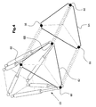
- a tractor 10 goes with a Interface, the six in the manner of a hexapod arranged hydraulic cylinders 12, 14, 16, 18, 20, 22 contains, the one ends in the rear area 24 of the work vehicle 10 and at the other end at the corner points of a vehicle-side Coupling triangle 26 are articulated. Details of a such mounting interface are in the post-published DE-A-199 51 840 described in more detail. Behind the tractor 10 there is a working tool, namely a plow 28 on which a coupling triangle 30 on the device side is attached. The Device-side coupling triangle 30 can be done in the usual way with the vehicle-side coupling triangle 26, for example Pair like a Weiste triangle.
- the signals of the two Cameras 34, 36 by an electronic one Image processing device 38 evaluated.
- the Image processing device 38 analyzes the images of the two cameras 34, 36 in terms of characteristic Picture elements and determined using known ones Image processing methods the spatial coordinates X1, Y1, Z1, ⁇ 1, ⁇ 1, and ⁇ 1 of the device-side coupling triangle 30 in Regarding the position of the vehicle body.
- displacement sensors 40 integrated, whose Output signals the respective stroke of the hydraulic cylinders 12, 14, 16, 18, 20, 22 corresponds.
- an electronic hexapod computing unit 42 calculates the spatial coordinates X, Y, Z, ⁇ , ⁇ , ⁇ of the vehicle side Coupling triangle or the vehicle-side coupling points in relation on the position of the fuselage.
- Control device 44 communicated which of these coordinates calculates the first section 46 of a trajectory. It is the first section 46 of the trajectory a straight line that defines the starting coordinates X, Y, Z, ⁇ , ⁇ , and ⁇ , the coupling frame on the vehicle side with the coordinates a target point 48, which is in a fixed spatial relation stands to the coupling frame 30 on the device side, connects.
- the rectilinear trajectory can coordinate rotations be overlaid.
- the control unit 44 there is a second fixed one Trajectory 50 saved by a learning mode has been determined and which depends on the type of concrete Coupling mechanism depends.
- the control device 44 is connected to an activation switch 52 which can be actuated by an operator. If an activation signal is emitted by the activation switch 52, the control unit 44 calculates control signals for proportional valves 54 from the first and the second movement path 46, 50, which supply corresponding oil quantities to the respective hydraulic cylinders 12, 14, 16, 18, 20, 22, so that these are extended or retracted in order to move the coupling frame 26 on the vehicle along the movement paths 46, 50 and to automatically approach the coupling frame 30 on the device and to carry out the coupling process. Furthermore, an operating unit 56, for example a joystick, which can be actuated by the operator is provided, which is connected to the control device 44 and serves for manual operation of the attachment interface.
- an operating unit 56 for example a joystick
- Fig. 5 In the embodiment shown in Fig. 5 are used for Scanning the coupling area instead of that in Fig. 1st optical cameras shown five laser sensors 70, 72, 74, 76, 78 used, each consisting of a transmitter and a Recipients exist.
- the laser sensors can be moved sideways pivot. They are arranged so that each laser sensor is aligned with an associated vertical plane.
- the Horizontal levels of the laser sensors are around one another given values offset by a distance h. From the scanned data from the laser sensors can be spatially Create a picture of the attachment area. Striking elements of the device 28 or the coupling triangle 30 are by the Evaluation device recognized, so that from this Have device-related coordinates calculated.
- the evaluation of the Data and control of the hexapod can be done in a similar way done as it is based on optical image processing has been described.
Abstract
Description
Die Erfindung betrifft eine Vorrichtung zum Koppeln eines Gerätes an ein Arbeitsfahrzeug, insbesondere einem landwirtschaftlichen oder industriellen Fahrzeug, mit einer Geräteschnittstelle, die fahrzeugseitige Koppelelemente und korrespondierende geräteseitige Koppelelemente aufweist. Um die räumlichen Lagen der fahrzeugseitigen Koppelelemente relativ zum Fahrzeug einstellen zu können, sind hierfür geeignete Einstellmittel vorgesehen.The invention relates to a device for coupling a Device to a work vehicle, especially one agricultural or industrial vehicle, with a Device interface, the vehicle-side coupling elements and has corresponding device-side coupling elements. To the spatial positions of the vehicle-side coupling elements relative to be able to adjust to the vehicle are suitable for this Adjustment means provided.
Es sind unterschiedliche Anbauschnittstellen, auch Gerätekopplungsvorrichtungen genannt, bekannt, durch die beispielsweise landwirtschaftliche Anbaugeräte an ein landwirtschaftlichen Fahrzeug, wie Ackerschlepper oder Erntemaschine, befestigbar sind. Dabei sind die fahrzeugseitigen Koppelelemente häufig nicht starr mit dem Fahrzeug verbunden sondern lassen sich relativ zum Fahrzeug bewegen, so dass sich auch das Anbaugerät relativ zum Fahrzeug bewegen lässt. Als Koppelelemente sind eine Vielzahl von Befestigungsmöglichkeiten bekannt, beispielsweise als Haken ausgebildete Kopplungspunkte oder Kopplungsplatten mit flächenartigen Kopplungsbereichen.There are different mounting interfaces, too Device coupling devices known, known by the for example, agricultural implements on agricultural vehicle, such as agricultural tractors or Harvester, can be fastened. Here are the vehicle-side coupling elements are often not rigid with the Vehicle connected but can be relative to the vehicle move so that the attachment is also relative to the vehicle can move. A large number of coupling elements are Fastening options known, for example as a hook trained coupling points or coupling plates areal coupling areas.
Die US-A-3,432,184 beschreibt eine Anbauvorrichtung für einen Traktor mit einer dreieckförmigen Koppelplatte, die über mehrere hydraulische und elektrische Aktuatoren mit dem Traktorrahmen in Verbindung steht und sich durch Betätigung der Aktuatoren relativ zum Fahrzeugrahmen innerhalb eines vorgegebenen Bewegungsraums translatorisch und rotatorisch bewegen lässt. Das Anbaugerät enthält ebenfalls eine dreieckförmige Anbauplatte, deren obere Kanten flanschartig umgebogen sind, so dass sie die entsprechenden Kanten der Koppelplatte aufnehmen können. Die bekannte Anbauvorrichtung soll eine einfache und schnelle Aufnahme von Anbaugeräten von der Fahrzeugkabine aus ermöglichen, ohne dass zuvor eine genaue Ausrichtung des Traktors zum Anbaugerät erfolgen muss. Zu diesem Zweck lassen sich die Aktuatoren von einer Bedienungskonsole in der Fahrzeugkabine aus ansteuern. Zum Ankoppeln wird zunächst die Koppelplatte abgesenkt, dann wird das Fahrzeug bewegt, um die Koppelplatte in die Nähe der Anbauplatte zu bringen, und schließlich werden bei stehendem Fahrzeug die Aktuatoren betätigt, um die beiden Platten zueinander auszurichten und gegebenenfalls miteinander zu verriegeln. Das Koppeln ist jedoch häufig schwierig, da die Bedienungsperson von der Fahrerkabine aus die Koppelstelle schlecht einsehen und die Abstände zwischen der Koppelplatte und der Anbauplatte schlecht abschätzen kann. Es ist viel Fingerspitzengefühl erforderlich, um den Koppelvorgang zuverlässig auszuführen. Dies erfordert Geduld und Zeit.US-A-3,432,184 describes an attachment for one Tractor with a triangular coupling plate that over several hydraulic and electrical actuators with the Tractor frame is connected and by pressing the Actuators relative to the vehicle frame within one given movement space translational and rotational can move. The attachment also contains one triangular mounting plate, the upper edges of which are flange-like are bent so that they match the corresponding edges of the Can accommodate coupling plate. The well-known attachment is designed for a simple and quick attachment of attachments from from the vehicle cabin without first having an exact Alignment of the tractor to the implement must be done. To for this purpose, the actuators can be Activate the control console in the vehicle cabin. To the Coupling is first lowered the coupling plate, then the vehicle moves to the coupling plate near the Bring mounting plate, and eventually stand still Vehicle actuated the actuators to the two plates align with each other and if necessary with each other lock. However, pairing is often difficult because the Operator from the driver's cab to the coupling point difficult to see and the distances between the coupling plate and the mounting plate is difficult to estimate. It is much Dexterity required to complete the coupling process perform reliably. This takes patience and time.
Um den Koppelvorgang zwischen Fahrzeug und einer Anhängerkupplung vom Fahrerplatz aus besser beobachten zu können, wurde durch die US-A-6,076,847 vorgeschlagen, auf der Anhängerdeichsel einen schräggestellten Spiegel derart über der Anhängekupplung zu montieren, dass die Bedienungsperson mit Hilfe des Spiegels die Anhängerkupplung von oben beobachten kann. Selbst mit diesem Hilfsmittel ist der Manövriervorgang beim Kuppeln schwierig.To the coupling process between vehicle and one Watch the towbar better from the driver's seat has been suggested by US-A-6,076,847, on which Trailer drawbar an inclined mirror so above the Mount the trailer hitch that the operator with Use the mirror to watch the towbar from above can. Even with this aid is the maneuvering process difficult when coupling.
Die der Erfindung zugrunde liegende Aufgabe wird darin gesehen, eine Koppelvorrichtung der eingangs genannten Art anzugeben, durch welche die vorgenannten Probleme überwunden werden. Insbesondere soll die Bedienungsperson entlastet und der Koppelvorgang erleichtert und beschleunigt werden, was zu Zeitund Kraftstoffeinsparungen führt.The object underlying the invention is seen in to specify a coupling device of the type mentioned at the outset, by which the aforementioned problems are overcome. In particular, the operator should be relieved and the Pairing process can be facilitated and accelerated, leading to time and Leads to fuel savings.
Die Aufgabe wird erfindungsgemäß durch die Lehre des Patentanspruchs 1 gelöst. Weitere vorteilhafte Ausgestaltungen und Weiterbildungen der Erfindung gehen aus den Unteransprüchen hervor.The object is achieved by the teaching of Claim 1 solved. Further advantageous configurations and further developments of the invention result from the subclaims out.
Die erfindungsgemäße Koppelvorrichtung enthält eine Geräteschnittstelle, die fahrzeugseitige Koppelelemente und korrespondierende geräteseitige Koppelelemente aufweist. Durch Einstellmittel lässt sich die räumliche Lage der fahrzeugseitigen Koppelelemente relativ zum Arbeitsfahrzeug einstellen. Die Erfindung schlägt die Verwendung wenigstens einer Sensoreinrichtung vor, welche die Lage der geräteseitigen Koppelelemente erkennt bzw. erfasst. Eine Auswerteeinrichtung ermittelt die relative Lage der geräteseitigen Koppelelemente zu den fahrzeugseitigen Koppelelementen. Eine Steuereinrichtung berechnet eine Bewegungsbahn für den Kopplungsvorgang und steuert aufgrund eines Startsignals die Einstellmittel derart an, dass der Kopplungsvorgang entlang der berechneten Bewegungsbahn vollautomatisch ausgeführt wird.The coupling device according to the invention contains a Device interface, the vehicle-side coupling elements and has corresponding device-side coupling elements. By The spatial position of the adjustment means Vehicle coupling elements relative to the work vehicle to adjust. The invention at least suggests the use a sensor device, which determines the position of the device Coupling elements recognized or detected. An evaluation device determines the relative position of the coupling elements on the device side to the coupling elements on the vehicle. A control device calculates a trajectory for the coupling process and controls the setting means based on a start signal indicates that the coupling process along the calculated Movement path is executed fully automatically.
Um eine Gerätekopplung vorzunehmen, wird die Arbeitsmaschine zunächst in die Nähe des Anbaugerätes gefahren. Bei der Annäherung des Arbeitsfahrzeuges zum Gerät wird durch eine Sensoreinrichtung und eine Auswerteeinrichtung die Lage der geräteseitigen Koppelelemente relativ zu einem vorgegebenen Punkt an der Arbeitsmaschine bzw. zu der Lage der geräteseitigen Koppelelementen ständig oder periodisch innerhalb vorgebarer Zeitintervalle erfasst. Dabei werden aus den durch die Sensoreinrichtung gewonnenen Messwerten die zugehörigen Koordinaten der geräteseitigen Koppelelemente berechnet und es wird laufend geprüft, ob sich die geräteseitigen Koppelelemente im Bewegungsbereich (Arbeitsraum) der fahrzeugseitigen Kopplungselemente befinden. Da sich die fahrzeugseitigen Koppelelemente durch die Einstellmittel innerhalb eines relativ großen Bewegungsbereichs einstellen lassen, hat der Fahrer zur Ausrichtung des Arbeitsfahrzeugs relativ zum Anbaugerät einen großen Spielraum und kann das Fahrzeug rasch an das Anbaugerät annähern.To make a device coupling, the work machine first moved close to the attachment. In the Approach of the work vehicle to the device is by a Sensor device and an evaluation device the location of the device-side coupling elements relative to a predetermined Point on the machine or on the location of the device-side coupling elements continuously or periodically recorded within predefined time intervals. Doing so the measured values obtained by the sensor device associated coordinates of the coupling elements on the device side calculated and it is continuously checked whether the device-side coupling elements in the range of motion (work area) of the vehicle-side coupling elements. Since the vehicle-side coupling elements by the setting means within a relatively large range of motion the driver has to align the work vehicle relative to the attachment a large margin and can Quickly approach the vehicle to the attachment.
Wenn das Fahrzeug in eine Lage gefahren wurde, in der sich die geräteseitigen Koppelelemente im Arbeitsraum befinden, wird durch die Auswerteeinrichtung eine geeignete Information, beispielsweise in Form eines akustischen oder optischen Signals, an die Bedienungsperson abgegeben. Die Bedienungsperson bringt nun das Arbeitsfahrzeug zum stehen und prüft, ob der Kopplungsbereich hindernisfrei ist und eine gefahrlose automatische Kopplung erfolgen kann. Ist dies der Fall, so aktiviert die Bedienungsperson, beispielsweise durch Betätigung eines Druckknopfschalters, den automatischen Koppelvorgang. Die Steuereinrichtung berechnet aus der aktuellen relativen Lage zwischen den fahrzeugseitigen und den geräteseitigen Koppelelementen eine Bewegungsbahn für den Koppelvorgang und steuert die Einstellmittel an, um die fahrzeugseitigen Koppelelemente automatisch entlang der berechneten Bewegungsbahn an die geräteseitigen Koppelelemente anzunähern. Bei der Berechnung der Bewegungsbahn wird die Lage der geräteseitigen Koppelpunkte als Ziel-Lage verwendet, die sich bei stehendem Arbeitsfahrzeug und Gerät nicht verändert. Die jeweilige Ist-Lage der fahrzeugseitigen Koppelpunkte wird durch eine geeignete mit den Einstellmitteln zusammenwirkende Sensorik erkannt bzw. erfasst.If the vehicle was driven into a position in which the device-side coupling elements are located in the work area suitable information from the evaluation device, for example in the form of an acoustic or optical Signal, given to the operator. The Operator now brings the work vehicle to a stop and checks whether the coupling area is unobstructed and one safe automatic coupling can take place. Is this the Case, the operator activates, for example by Actuation of a push button switch, the automatic Coupling process. The control device calculates from the current relative position between the vehicle side and the device-side coupling elements a trajectory for the Coupling process and controls the setting means to the vehicle-side coupling elements automatically along the calculated movement path to the coupling elements on the device side to approach. When calculating the trajectory, the location the device-side crosspoints used as the target location, the does not change when the work vehicle and device are stationary. The actual position of the coupling points on the vehicle is by a suitable one which interacts with the setting means Sensors recognized or recorded.
Die erfindungsgemäße Koppelvorrichtung erlaubt einen weitgehend automatisierten Koppelvorgang zwischen Arbeitsfahrzeug und Anbaugerät, der keine besonderen Anforderungen an die Geschicklichkeit und Erfahrung der Bedienungsperson stellt. Durch die Bereitstellung eines automatischen Kuppelvorgangs wird die Bedienungsperson entlastet und kann ihre Aufmerksamkeit voll auf Sicherheitsaspekte richten, beispielsweise darauf, ob Personen durch den Koppelvorgang gefährdet werden oder ob sich Hindernisse im Koppelbereich befinden. Der Koppelvorgang kann zügig durchgeführt werden, weil er automatisch abläuft und nicht von der Geschicklichkeit der Bedienungsperson abhängt. Dies führt zu Zeit- und Kraftstoffeinsparungen.The coupling device according to the invention largely allows one automated coupling process between work vehicle and Attachment that has no special requirements for the Operator skill and experience. By providing an automatic coupling process the operator is relieved and can their Pay full attention to security aspects, For example, whether people are through the pairing process endangered or whether there are obstacles in the coupling area are located. The coupling process can be carried out quickly, because it runs automatically and not from skill depends on the operator. This leads to time and Fuel savings.
Vorzugsweise sind die fahrzeugseitigen Koppelelemente auf einem Kopplungsrahmen angeordnet, der durch längenveränderliche Einstellmittel mit dem Fahrzeug in Verbindung steht. Als Einstellmittel kommen beispielsweise ein- oder doppelseitig wirkende Hydraulikzylinder in Betracht. Es können jedoch auch andere hydraulische oder elektromechanische Stellelemente verwendet werden. Der Koppelrahmen kann vielfältig ausgebildet sein. Beispielsweise ist er eine im wesentlichen dreieckförmige Platte, die als Einphasenkuppler ausgebildet ist und an deren Eckpunkten die Einstellmittel angreifen, wie es aus der US-A-3,432,184 hervorgeht. Der Koppelrahmen kann auch die Form eines gleichschenkligen oder gleichseitigen Dreieckrahmens haben, an dessen Eckpunkten einerseits die Einstellmittel gelenkig angreifen und andererseits Kopplungselemente in Form von Haken und dergleichen befestigt sind, wie es aus der nachveröffentlichten DE-A-199 51 840 hervorgeht. Es kann sich bei dem Koppelrahmen auch um einen Portalrahmen handeln mit einem oberen Horizontalbalken und zwei seitlichen Vertikalbalken (US-A-5,092,409).The coupling elements on the vehicle are preferably on one Coupling frame arranged by variable length Setting means is connected to the vehicle. As Adjustment means come, for example, on one or both sides acting hydraulic cylinders into consideration. However, it can also other hydraulic or electromechanical control elements be used. The coupling frame can be designed in many ways his. For example, it is essentially triangular Plate which is designed as a single-phase coupler and at the Key points attack the adjusting means, as is known from US-A-3,432,184 evident. The coupling frame can also have the shape of a have isosceles or equilateral triangular frames whose corner points on the one hand articulate the adjusting means attack and on the other hand coupling elements in the form of hooks and the like are attached, as from the post-published DE-A-199 51 840 emerges. It can act in the coupling frame also with a portal frame an upper horizontal bar and two lateral ones Vertical bar (US-A-5,092,409).
Eine besonders bevorzugte Ausgestaltung der Erfindung sieht vor, dass die Koppelvorrichtung wenigstens sechs längenverstellbare Einstellmittel enthält, deren jeweils erstes Ende gelenkig mit dem Fahrzeug verbunden ist und deren jeweils zweites Ende gelenkig mit einem Kopplungsrahmen, auf dem die Kopplungselemente angeordnet sind, in Verbindung steht. Die Einstellmittel sind dabei in geschlossenen kinematischen Ketten angeordnet und ermöglichen die Bewegung des Kopplungsrahmens in sechs Freiheitsgraden. Eine derartige Anordnung der Einstellmittel geht aus der nachveröffentlichten DE-A-199 51 840 hervor, auf deren Offenbarung hiermit Bezug genommen wird. Durch diese Anordnung lassen sich die Koppelelemente oder Koppelpunkte innerhalb weiter Grenzen innerhalb eines großen Arbeitsraumes in sechs Freiheitsgraden beliebig bewegen und einstellen. Dies begünstigt es, dass schon bei grober Positionierung des Arbeitsfahrzeugs eine automatische Kopplung erfolgen kann.A particularly preferred embodiment of the invention provides before that the coupling device at least six contains adjustable length adjustment means, the first of which End is articulated to the vehicle and their respective second end articulated with a coupling frame on which the Coupling elements are arranged, is connected. The Adjustment means are in closed kinematic chains arranged and allow the movement of the coupling frame in six degrees of freedom. Such an arrangement of Setting means goes from the subsequently published DE-A-199 51 840, the disclosure of which is hereby incorporated by reference. With this arrangement, the coupling elements or Crosspoints within wide limits within a large one Move the work space in six degrees of freedom and to adjust. This favors that even at gross Positioning the work vehicle an automatic coupling can be done.
Vorzugsweise sind die Einstellmittel nach Art eines Hexapoden angeordnet. Eine Hexapod-Anordnung wird beispielsweise in der nachveröffentlichten DE-A-199 51 840 beschrieben. Die Einstellmittel sind mit Wegsensoren ausgestattet, aus deren Messwerten sich die jeweilige räumlichen Ist-Lage des Kopplungsrahmens und damit auch die Ist-Lagen der Koppelelemente oder Kopplungspunkte bestimmen lassen. Hierbei können bekannte Berechnungsmethoden angewendet werden (Hebsacker, M.: Die Auslegung der Kinematik des Hexaglide - Methodik für die Auslegung paralleler Werkzeugmaschinen, VDI Berichte Nr. 1427, 1998).The setting means are preferably in the manner of a hexapod arranged. A hexapod arrangement is used, for example, in the described in DE-A-199 51 840. The Setting devices are equipped with displacement sensors, from whose The actual spatial position of the Coupling frame and thus also the actual locations of the Have coupling elements or coupling points determined. in this connection known calculation methods can be used (Hebsacker, M .: The interpretation of the kinematics of the hexaglide - Methodology for the design of parallel machine tools, VDI Reports No. 1427, 1998).
Gemäß einer vorteilhaften Weiterbildung der Erfindung sind Sensoren zur Längenmessung der längenverstellbaren Einstellmittel vorgesehen. Aus den Messwerten der Sensoren lassen sich die Koordinaten der Koppelpunkte des Hexapod-Anbaus berechnen. Die Sensoren können beispielsweise in die Hydraulikzylinder einer Hexapod-Anordnung integriert sein.According to an advantageous development of the invention Sensors for measuring the length of the adjustable Adjustment means provided. From the measured values of the sensors the coordinates of the coupling points of the hexapod cultivation to calculate. The sensors can, for example, in the Hydraulic cylinders of a hexapod arrangement can be integrated.
Als Sensoreinrichtung für die Erkennung der räumlichen Lage der geräteseitigen Koppelpunkte kommen eine Reihe bekannter Verfahren in Betracht, die bisher für andere Anwendungszwecke verwendet wurden.As a sensor device for the detection of the spatial position of the device-side crosspoints come a number of known Processes considered so far for other uses were used.
Ein geeignetes Verfahren für die Positionserkennung bedient sich der Bildverarbeitung, durch welche die Signale einer oder mehrerer Kameras ausgewertet werden. Beispielsweise werden zwei Kameras seitlich nebeneinander in den Eckpunkten des Fahrzeugkabinendachs montiert und auf die geräteseitige Kopplungsstruktur ausgerichtet. Die Kameras nehmen die Kopplungsstruktur in fester geometrischer Anordnung auf und erkennen charakteristische Merkmale der zu messenden Kopplungsstruktur. Sie übertragen die digitalen Bilder zu einem Steuergerät, in dem die Bilder mit entsprechender Software verarbeitet werden, um die Koordinaten der geräteseitigen Koppelelemente oder Kopplungspunkte zu berechnen.A suitable method is used for position detection the image processing by which the signals of one or multiple cameras can be evaluated. For example, two Cameras side by side in the corner points of the Vehicle cabin roof mounted and on the device side Coupling structure aligned. The cameras take them Coupling structure in a fixed geometric arrangement on and recognize characteristic features of the measured Coupling structure. You transfer the digital images to one Control unit in which the pictures with the appropriate software processed to the coordinates of the device To calculate coupling elements or coupling points.
Bei der Auswertung werden Bildverarbeitungsmethoden verwendet, wie sie bei der Automatisierung in der industriellen Fertigungstechnik für die Lageerkennung eines Werkstückes im Raum eingesetzt werden. Nach einer bekannten Methode werden zuerst charakteristische, optisch hervortretende Bereiche, beispielsweise Ecken oder Bohrungen, eines Werkstücks ermittelt, die anschließend mit Hilfe einer Relaxation den entsprechenden charakteristischen Bereichen eines bekannten Prototypen zugeordnet werden. Über die Zuordnung kann dann die Lage des gesamten Werkstücks ermittelt werden.Image processing methods are used in the evaluation, like automation in industrial Manufacturing technology for the position detection of a workpiece in Space. According to a known method first characteristic, optically prominent areas, for example corners or bores of a workpiece determined, which then with the help of a relaxation corresponding characteristic areas of a known Prototypes. You can then use the assignment The position of the entire workpiece can be determined.
Vorzugsweise werden durch die beiden Kameras auch Teile der Einstellmittel, insbesondere des Hexapods, aufgenommen, so dass bei der Verarbeitung der Bilder die Koordinaten der geräteseitigen Kopplungspunkte relativ zum Hexapodanbau ermittelt werden. Dies erlaubt die Korrektur von Fehlern, die durch Montagetoleranzen bei der Befestigung der beiden Kameras oder durch geringfügige Verschiebungen der Kameras infolge des Fahrzeugbetriebs verursacht werden.Preferably, the two cameras also use parts of the Adjustment means, especially the Hexapod, added, see above that when processing the images, the coordinates of the coupling points on the device side relative to the hexapod attachment be determined. This allows the correction of errors that due to assembly tolerances when attaching the two cameras or by slight displacements of the cameras due to the Vehicle operation are caused.
In Abhängigkeit von der verwendeten Bildverarbeitungssoftware werden Schwarzweiß- oder Farbkameras eingesetzt. Die Bildverarbeitungsmethode hat den Vorteil, dass selbst dann, wenn bei der Vermessung ein charakteristisches Merkmal ganz oder teilweise ausfällt (z.B. wenn dieses Merkmal durch Bauteile verdeckt wird), sich die Lage der Kopplungspunkte noch eindeutig bestimmen lässt. Eine entsprechende Software für den Roboter-Einsatz wird durch die Fa. ISRA Vision Systems AG, Darmstadt, DE angeboten.Depending on the image processing software used black and white or color cameras are used. The Image processing method has the advantage that even then, if in the measurement a characteristic feature entirely or partially fails (e.g. if this characteristic is due to Components is covered), the location of the coupling points can still be clearly determined. Appropriate software for the use of robots by ISRA Vision Systems AG, Darmstadt, DE.
Bei einer weiteren Sensoreinrichtung für die Erkennung der räumlichen Orientierung und Position der geräteseitigen Koppelpunkte werden sogenannte "3D magnetische Sensoren" verwendet. Hierbei wird von einem auf dem Gerät befestigten Transmitter über drei feste Antennen ein niedrigfrequentes Feld erzeugt, das von einem Receiver an der Arbeitsmaschine gemessen wird. Hier können dann die Position und Orientierung der Kopplungspunkte des Gerätes algorithmisch bestimmt, und dem Steuerungsgerät übermittelt werden.In a further sensor device for the detection of spatial orientation and position of the device Crosspoints become so-called "3D magnetic sensors" used. This is done by one attached to the device Transmitter over three fixed antennas a low-frequency field generated that measured by a receiver on the work machine becomes. The position and orientation of the Coupling points of the device algorithmically determined, and the Control device are transmitted.
Als Alternative zu magnetischen Sensoren können Ultraschall-Sensoren verwendet werden. Ultraschall Sensoren bestehen aus drei Komponenten: einem Transmitter, einem Receiver und einer elektronischen Einheit. Der Transmitter besteht aus drei Ultraschallgebern, die dreiecksförmig an dem Gerät angebracht sind. Korrespondierend dazu ist ein kleines Dreieck von Ultraschallmikrophonen auf der Arbeitsmaschine angebracht. In dem Steuerungsgerät werden die Daten der Mikrophone in Koordinaten der Kopplungspunkte konvertiert und an die Hexapodsteuerung übermittelt. Da es sich hier um Schallwellen handelt, ist dieses System anfällig gegenüber fremden Schallquellen. Über das Multiplexen mehrerer Transmitter kann das Problem der direkten Verbindung zwischen Transmitter und Receiver auf Kosten der Updaterate gelöst werden. Die Ultaschalllösungen bieten billige und ausreichend gute Alternativen zu magnetischen Sensoren.Ultrasound sensors can be used as an alternative to magnetic sensors be used. Ultrasonic sensors consist of three components: a transmitter, a receiver and one electronic unit. The transmitter consists of three Ultrasound sensors, which are attached to the device in a triangular shape are. Corresponding to that is a small triangle of Ultrasound microphones attached to the work machine. In The data of the microphones are in the control device Coordinates of the coupling points converted and to the Hexapod control transmitted. Since this is sound waves this system is vulnerable to strangers Sound sources. By multiplexing multiple transmitters the problem of the direct connection between transmitter and Receiver will be solved at the expense of the update rate. The Ultrasonic solutions offer cheap and sufficiently good ones Alternatives to magnetic sensors.
Eine weitere Sensoreinrichtung für die Erkennung der räumlichen Lage der geräteseitigen Koppelpunkte bedient sich Laser-Sensoren, wie sie beispielsweise bei der automatischen Lenkung für Mähdrescher für die Erkennung der Bestandskante eingesetzt werden ("Die Augen des Mähdreschers", Profi 12 (1999), S. 48-49). Eine derartige Sensoreinrichtung besteht beispielsweise aus zwei Laser-Sensoren, einem Sender und einem Empfänger, die im Kabinendachbereich des Arbeitsfahrzeuges montiert werden und sich um einen festen Winkelbereich von einigen Grad hin und her verschwenken lassen. Aus dem Schwenkwinkel und dem Abstand zum Gerät ergibt sich der abgetastete Bereich. Der Sensor strahlt Infrarot-Laserstrahlen mit beispielsweise 60 MHz Pulsfrequenz ab. Der Empfänger erfasst die von charakteristischen Bereichen, wie Rahmenteilen und dergleichen reflektierten Strahlen. Aus den Reflexionsdaten berechnet ein Prozessor die Lage des charakteristischen Bereichs und leitet hieraus die Lage der Kupplungspunkte ab.Another sensor device for the detection of spatial The location of the coupling points on the device uses laser sensors, like for example in automatic steering used for combine harvesters to identify crop edges become ("The eyes of the combine", Profi 12 (1999), pp. 48-49). Such a sensor device exists, for example from two laser sensors, a transmitter and a receiver, the be installed in the cab roof area of the work vehicle and back and forth around a fixed angular range of a few degrees let swivel. From the swivel angle and the distance to the The scanned area results from the device. The sensor shines Infrared laser beams with a pulse frequency of 60 MHz, for example from. The receiver captures those of characteristic areas, such as frame parts and the like reflected rays. Out A processor calculates the position of the reflection data characteristic area and derives from this the location of the Coupling points.
Für die Ermittlung der Lage des Gerätekopplungsrahmens muss der Scan-Vorgang räumlich durchgeführt werden. Das bedeutet, dass der Sender und der Empfänger des Laser-Sensors nicht nur in einer Ebene, sondern in zwei zueinander senkrechten Ebenen bewegt werden sollte. Es können auch mehrere Laser-Sensoren, die jeweils aus einem Sender und einem Empfänger bestehen, eingesetzt werden. Dabei werden die Sender und Empfänger jedes Laser-Sensors in einer eigenen zugehörigen horizontalen Ebene bewegt. Die horizontalen Ebenen aller Laser-Sensoren sind voneinander in vertikaler Richtung um vorgegebene Werte versetzt. Somit wird aus den Daten aller Laser-Sensoren ein räumliches Bild des gescannten Raums erstellt. Die Sensoren sollen dabei so auf der Arbeitsmaschine plaziert werden, dass die Geräteschnittstelle, insbesondere der Hexapod, nicht in dem Scan-Bereich liegt, so dass die Messwerte der Laser-Sensoren bei ihrer Bewegung nicht oder nur geringfügig beeinflusst werden. Um dies zu erreichen können beispielsweise Laser-Sensoren in das Hexapod integriert werden, indem sie z.B. in der Nähe des Kopplungsrahmens bzw. auf diesem montiert werden.To determine the position of the device coupling frame, the Scanning process can be performed spatially. It means that the transmitter and receiver of the laser sensor not only in one plane, but in two mutually perpendicular planes should be moved. It is also possible to use several laser sensors, each consisting of a transmitter and a receiver, be used. The transmitter and receiver are each Laser sensor in its own associated horizontal plane emotional. The horizontal levels of all laser sensors are from each other in the vertical direction by predetermined values added. Thus, the data from all laser sensors creates a spatial image of the scanned space. The sensors should be placed on the machine so that the device interface, especially the Hexapod, not in the Scanning area lies so that the measured values of the laser sensors not influenced or only slightly influenced during their movement become. To achieve this, for example, laser sensors be integrated into the hexapod, e.g. by in close to the coupling frame or mounted on it.
Des weiteren kann die Lage der geräteseitigen Koppelelemente bzw. Kopplungspunkten und ihre relative Zuordnung zu den fahrzeugseitigen Koppelelementen bzw. Kopplungspunkten unter Verwendung der GPS-Technik (Global Positioning System) bestimmt werden, indem entsprechende GPS-Empfänger auf dem Arbeitsfahrzeug und dem zu koppelnden Gerät montiert werden und die GPS-Signale entsprechend ausgewertet werden. Zur Bestimmung der räumlichen Ausrichtung der Koppelelemente können beispielsweise sowohl auf dem Arbeitsfahrzeug als auch auf dem Gerät je drei GPS-Systeme montiert werden.Furthermore, the position of the coupling elements on the device side or coupling points and their relative assignment to the vehicle-side coupling elements or coupling points below Use of GPS technology (Global Positioning System) can be determined by using appropriate GPS receivers on the Work vehicle and the device to be coupled and the GPS signals are evaluated accordingly. to Determination of the spatial alignment of the coupling elements can, for example, both on the work vehicle and three GPS systems can be installed on the device.
Es sind auch weitere Messsysteme zur Bestimmung der relativen räumlichen Lage der fahrzeugseitigen und der geräteseitigen Koppelelemente verwendbar. Beispielsweise können Radarsender verwendet werden, welche die Reflexionssignale von Reflektoren empfangen und auswerten, die auf dem zu koppelnden Gerät montiert sind.There are also other measurement systems to determine the relative spatial position of the vehicle side and the device side Coupling elements can be used. For example, radar transmitters are used, which reflect signals from reflectors receive and evaluate that on the device to be paired are mounted.
Gemäß einer zweckmäßigen Weiterbildung der Erfindung ist ein durch eine Bedienungsperson betätigbares Bedienungselement vorgesehen, das der Aktivierung des automatischen Koppelvorgangs dient. Vor der Auslösung des automatischen Koppelvorganges prüft die Bedienungsperson, ob der Kopplungsbereich hindernisfrei ist. Vorzugsweise kann die Bedienungsperson das Bedienungselement auch verwenden, um jederzeit den automatischen Koppelvorgang abzubrechen.According to an expedient development of the invention, a operating element operable by an operator provided that the activation of the automatic Coupling process is used. Before triggering the automatic Coupling checks the operator whether the Coupling area is unobstructed. Preferably, the Operator also use the control to cancel the automatic coupling process at any time.
Der Koppelvorgang sollte aus Sicherheitsgründen nur bei stehender Arbeitsmaschine und bei stehendem Gerät durchgeführt werden. Es ist daher zweckmäßig, dass die Steuereinrichtung eine Abschaltfunktion enthält, die Relativbewegungen zwischen dem Arbeitsfahrzeug und dem zu koppelnden Gerät wahrnimmt und die bei Überschreiten eines vorgebbaren Relativbewegungswertes den automatischen Koppelvorgang abbricht. Beispielsweise wird während eines automatischen Koppelvorganges, d. h. während der automatischen Annäherung, die Ist-Lage der geräteseitigen Kopplungspunkte periodisch in vorgebbaren Zeitintervallen gemessen. Diese Werte werden mit der berechneten Soll-Lage für die Bewegungsbahn verglichen. Übersteigt die Abweichung zwischen Ist-Lage und Soll-Lage einen vorgebbaren Wert, so ist dies ein Indiz dafür, dass sich die Lage der geräteseitigen Kopplungspunkte relativ zur Position der Arbeitsmaschine geändert hat, was bedeuten kann, das sich die Arbeitsmaschine und/oder das Gerät relativ zum Boden bewegt. Der automatische Koppelvorgang wird dann abgebrochen und lässt sich durch einen durch die Bedienungsperson ausgelösten Aktivierungsbefehl wieder in Gang setzen, wobei die Lage der geräteseitigen Kopplungspunkte erneut zur Steuereinrichtung übertragen werden, die eine neue Bewegungsbahn berechnet. Bei kleinen Abweichungen zwischen der Ist-Lage und der Soll-Lage wird der Koppelvorgang nicht abgebrochen.The coupling process should only for security reasons stationary machine and with the machine stationary become. It is therefore appropriate that the control device a shutdown function that contains relative movements between perceives the work vehicle and the device to be coupled and when a predeterminable relative movement value is exceeded aborts the automatic pairing process. For example during an automatic coupling process, d. H. during the automatic approximation, the actual position of the device Coupling points periodically at predefinable time intervals measured. These values are calculated with the calculated target position for compared the trajectory. Exceeds the deviation between the actual position and the target position is a predeterminable value this is an indication that the position of the device Coupling points relative to the position of the working machine has changed, which can mean that the work machine and / or the device moves relative to the ground. The automatic The coupling process is then canceled and can be started by one activation command triggered by the operator start again, the position of the device Coupling points are transmitted to the control device again, which calculates a new trajectory. With small deviations the coupling process is between the actual position and the target position not canceled.
Häufig erfolgt das Ankoppeln nicht lediglich durch eine geradlinige Annäherung zwischen den fahrzeugseitigen Koppelpunkten an die geräteseitigen Koppelpunkte. Werden beispielsweise Koppelhaken verwendet, so muss im letzten Abschnitt der Annäherung ein Einhängen erfolgen, was z. B. einen vertikalen Verlauf der Bewegungsbahn erfordern kann. Often the coupling is not done by just one rectilinear approach between the vehicle side Coupling points to the device-side coupling points. Become For example, coupling hooks used in the last Section of the approximation hooking in what z. B. may require a vertical trajectory.
Dieser letzte Abschnitt lässt sich jedoch nicht auf einfache Weise aufgrund der gemessenen Lagen der Koppelelemente durch die Steuereinrichtung berechnen. Eine bevorzugte Weiterbildung der Erfindung sieht daher vor, dass wenigstens ein Abschnitt der Bewegungsbahn in der Steuereinrichtung vorprogrammiert ist. Dabei sollen Parameter für die Bewegungsbahn durch die Steuerung vorgegeben werden. Diese Parameter werden aus dem Kopplungsvorgang und den Geometriedaten des jeweiligen Koppelsystems abgeleitet.However, this last section is not easy Way through based on the measured positions of the coupling elements calculate the control device. A preferred training The invention therefore provides that at least one section the movement path preprogrammed in the control device is. Thereby parameters for the trajectory through the Control can be specified. These parameters are derived from the Coupling process and the geometry data of each Coupling system derived.
Der vorprogrammierte Abschnitt der Bewegungsbahn hängt von der Art des jeweiligen Kopplungsmechanismus ab. Zur Kopplung unterschiedlicher Anbaugeräte können mehrere, auf die jeweiligen Anbaugeräte abgestimmte Bewegungsbahnabschnitte vorprogrammiert und dann durch eine geeignete Eingabevorrichtung durch die Bedienungsperson ausgewählt werden. Soll beispielsweise eine Kopplung nach Art eines sogenannten Weiste-Dreiecks (DE-AS-1 215 419) erfolgen, wird zunächst durch eine automatische Annäherung längs der berechneten Bewegungsbahn das fahrzeugseitige Weiste-Dreieck in die Nähe des geräteseitigen Fangdreiecks gebracht und zu diesem parallel ausgerichtet. Mit Erreichen einer definierten Relativlage erfolgt die Steuerung anhand der vorprogrammierten Bewegungsbahn. Dabei wird das Weiste-Dreieck parallel zum Fangdreieck geführt bis es sich unter dem Fangdreieck befindet und kopplungsbereit ist. In einem letzten vorprogrammierten Bewegungsabschnitt wird das Weiste-Dreieck nach oben in das Fangdreieck eingeschoben, wobei die beiden Dreiecke miteinander arretiert werden. Die einzelnen Abschnitte der Bewegungsbahn können gerade Linien sein. Gegebenenfalls müssen jedoch Hindernisse berücksichtigt werden.The preprogrammed section of the trajectory depends on the Type of the respective coupling mechanism. For coupling Different attachments can have multiple attachments coordinated movement path sections for the respective attachments preprogrammed and then by a suitable one Input device selected by the operator become. For example, if a coupling of the type so-called Weiste triangle (DE-AS-1 215 419) will take place first by an automatic approach along the calculated trajectory the vehicle-side Weiste triangle in brought the proximity of the device-side catch triangle and to this aligned in parallel. When a defined one is reached Relative position control is based on the pre-programmed Trajectory. The Weiste triangle becomes parallel to Catch triangle guided until it is under the catch triangle and is ready to pair. In a last preprogrammed Movement section becomes the Weiste triangle up in that Catch triangle inserted, the two triangles together be locked. The individual sections of the trajectory can be straight lines. If necessary, however Obstacles are taken into account.
Die Programmierung der vorprogrammierten Bewegungsbahn kann schwierig sein. Eine vorteilhafte Ausgestaltung der Erfindung sieht einen Lernmodus zum Erlernen des Verlaufs dieser Bewegungsbahn vor. Zur Durchführung des Lernmodus steuert die Bedienungsperson zunächst den fahrzeugseitigen Koppelrahmen durch Betätigung von entsprechenden Stellelementen so an, dass der fahrzeugseitige Koppelrahmen eine Ausgangslage in der Nähe des geräteseitigen Koppelrahmens einnimmt. Dann aktiviert die Bedienungsperson einen Lernmodus, setzt den Koppelvorgang von Hand fort, beendet diesen und erzeugt schließlich ein Endsignal, um der Steuereinrichtung das Ende des Lernmodus anzuzeigen. Während des Lernmodus zeichnet die Steuereinrichtung die Bewegungsparameter des fahrzeugseitigen Koppelrahmens auf. Beim späteren Ausführen des automatischen Koppelvorgangs, wird die im Lernmodus erlernte Bewegung durch die Steuereinrichtung nachgebildet.The programming of the preprogrammed trajectory can to be difficult. An advantageous embodiment of the invention sees a learning mode for learning the course of this Trajectory before. The controls the Operator first the coupling frame on the vehicle by actuating appropriate control elements so that the coupling frame on the vehicle has a starting position nearby of the coupling frame on the device side. Then activate the Operator a learning mode, sets the pairing process of Hand on, finish this and finally generate one End signal to the control device the end of the learning mode display. During the learning mode, the Control device the movement parameters of the vehicle side Coupling frame. When you later run the automatic Coupling process, the movement learned in the learning mode simulated the control device.
Werden während des automatischen Koppelvorgangs Hindernisse durch die Sensor- und Auswerteeinrichtung erkannt, wird der Koppelvorgang automatisch abgebrochen. Er kann durch ein von der Bedienungsperson ausgelöstes Startsignal wieder fortgesetzt werden.Become obstacles during the automatic coupling process recognized by the sensor and evaluation device, the Pairing process automatically canceled. He can by one of the operator triggered start signal resumed become.
Anhand der Zeichnung, die Ausführungsbeispiele der Erfindung zeigt, werden nachfolgend die Erfindung sowie weitere Vorteile und vorteilhafte Weiterbildungen und Ausgestaltungen der Erfindung näher beschrieben und erläutert.Based on the drawing, the embodiments of the invention shows, the invention and further advantages are below and advantageous developments and refinements of Invention described and explained in more detail.
Es zeigt:
- Fig. 1
- die Seitenansicht eines Ackerschleppers und eines Pflugs, die durch eine Anbauschnittstelle miteinander koppelbar sind und eine optische Sensoreinrichtung zur Automatisierung des Koppelvorgangs enthalten,
- Fig. 2
- die perspektivische Prinzipskizze der in Fig. 1 dargestellten Anbauschnittstelle in Richtung Fahrzeugheck gesehen,
- Fig. 3
- das Blockdiagramm einer erfindungsgemäßen Steuervorrichtung zum Koppeln eines Gerätes an ein Arbeitsfahrzeug,
- Fig. 4
- einen Hexapodanbau mit magnetischen bzw. akustischen Sensoreinrichtungen und
- Fig. 5
- eine der Fig. 1 entsprechende Darstellung, bei der anstelle einer optischen Sensoreinrichtung Laser-Sensoren verwendet werden.
- Fig. 1
- the side view of a tractor and a plow, which can be coupled to each other through an attachment interface and contain an optical sensor device for automating the coupling process,
- Fig. 2
- the perspective schematic diagram of the mounting interface shown in Fig. 1 seen towards the rear of the vehicle,
- Fig. 3
- the block diagram of a control device according to the invention for coupling a device to a work vehicle,
- Fig. 4
- a Hexapodanbau with magnetic or acoustic sensor devices and
- Fig. 5
- a representation corresponding to FIG. 1, in which laser sensors are used instead of an optical sensor device.
Aus den Figuren 1 und 2 geht ein Ackerschlepper 10 mit einer
Anbauschnittstelle hervor, die sechs nach Art eines Hexapoden
angeordnete Hydraulikzylinder 12, 14, 16, 18, 20, 22 enthält,
die einenends im Heckbereich 24 des Arbeitsfahrzeugs 10 und
anderenends an den Eckpunkten eines fahrzeugseitigen
Koppeldreiecks 26 gelenkig befestigt sind. Einzelheiten einer
derartigen Anbauschnittstelle sind in der nachveröffentlichten
DE-A-199 51 840 näher beschrieben. Hinter dem Ackerschlepper 10
befindet sich ein Arbeitsgerät, nämlich ein Pflug 28, an dem
ein geräteseitiges Koppeldreieck 30 befestigt ist. Das
geräteseitige Koppeldreieck 30 lässt sich auf übliche Weise
mit dem fahrzeugseitigen Kopplungsdreieck 26, beispielsweise
nach Art eines Weiste-Dreiecks koppeln. Zur Kopplung können
auch in den Eckpunkten des fahrzeugseitigen Koppeldreiecks 26
nicht dargestellte, nach hinten vorstehende und nach oben
offene Fanghaken verwendet werden, die zum Koppeln in
entsprechende, an dem geräteseitigen Koppeldreieck 30
angebrachte Aufnahmen eingreifen. Bei den Fanghaken und
Aufnahmen handelt es sich um die oben erwähnten Koppelelemente
oder Koppelpunkte.From Figures 1 and 2, a
In den seitlichen Eckpunkten des Fahrzeugkabinendachs 32 sind
zwei Kameras 34, 36 befestigt, von denen in Fig. 1 nur eine
sichtbar ist und die auf die Anbauschnittstelle, insbesondere
auf das geräteseitige Koppeldreieck 30 ausgerichtet sind und
den Koppelbereich überwachen.In the side corner points of the vehicle cabin roof 32 are
two
Wie aus Fig. 3 hervorgeht, werden die Signale der beiden
Kameras 34, 36 durch eine elektronische
Bildverarbeitungseinrichtung 38 ausgewertet. Die
Bildverarbeitungseinrichtung 38 analysiert die Bilder der
beiden Kameras 34, 36 hinsichtlich charakteristischer
Bildelemente und bestimmt unter Verwendung bekannter
Bildverarbeitungsmethoden die räumlichen Koordinaten X1, Y1,
Z1, α1, β1, und γ1 des geräteseitigen Koppeldreiecks 30 in
Bezug auf die Lage des Fahrzeugrumpfs.As can be seen from Fig. 3, the signals of the two
In den Hydraulikzylindern 12, 14, 16, 18, 20, 22 des Hexapods
sind nicht näher dargestellte Wegsensoren 40 integriert, deren
Ausgangssignale dem jeweiligen Hub der Hydraulikzylinder 12,
14, 16, 18, 20, 22 entspricht. Aus den Wegsensorsignalen
berechnet eine elektronische Hexapod-Recheneinheit 42 die
räumlichen Koordinaten X, Y, Z, α, β, γ des fahrzeugseitigen
Koppeldreiecks bzw. der fahrzeugseitigen Koppelpunkte in Bezug
auf die Lage des Fahrzeugrumpfs.In the
Die von der Bildverarbeitungseinheit 38 und von der Hexapod-Recheneinheit
42 berechneten Koordinaten werden einer
Steuereinrichtung 44 mitgeteilt, welche aus diesen Koordinaten
den ersten Abschnitt 46 einer Bewegungsbahn berechnet. Es
handelt sich bei dem ersten Abschnitt 46 der Bewegungsbahn um
eine gerade Linie, welche die Anfangskoordinaten X, Y, Z, α, β,
und γ, des fahrzeugseitigen Koppelrahmens mit den Koordinaten
eines Zielpunktes 48, der in einer festen räumlichen Relation
zum geräteseitigen Koppelrahmen 30 steht, verbindet. Der
geradlinigen Bewegungsbahn können Koordinatendrehungen
überlagert sein. In der Steuereinheit 44 ist eine zweite feste
Bewegungsbahn 50 gespeichert, die durch einen Lernmodus
ermittelt worden ist und die von der Art des konkreten
Koppelmechanismus abhängt.That from the
Die Steuereinrichtung 44 steht mit einem durch eine
Bedienungsperson betätigbaren Aktivierungsschalter 52 in
Verbindung. Wird durch den Aktivierungsschalter 52 ein
Aktivierungssignal abgegeben, so berechnet die Steuereinheit 44
aus der ersten und der zweiten Bewegungsbahn 46, 50
Steuersignale für Proportionalventile 54, welche entsprechende
Ölmengen an die jeweiligen Hydraulikzylinder 12, 14, 16, 18,
20, 22 liefern, so dass diese aus- bzw. eingefahren werden, um
den fahrzeugseitigen Koppelrahmen 26 längs der Bewegungsbahnen
46, 50 zu bewegen und automatisch an den geräteseitigen
Koppelrahmen 30 anzunähern und den Koppelvorgang auszuführen.
Es ist des weiteren eine durch die Bedienungsperson betätigbare
Bedienungseinheit 56, beispielsweise ein Joystick, vorgesehen,
die mit der Steuereinrichtung 44 in Verbindung steht und der
manuellen Bedienung der Anbauschnittstelle dient.The
Furthermore, an operating
Anstelle einer Bildverarbeitung, wie sie aus den Figuren 1 und
3 hervorgeht, können auch andere Sensoreinrichtungen zur
Erkennung der räumlichen Lage der geräteseitigen Koppelpunkte
verwendet werden. In Fig. 4 ist beispielsweise eine an einem
nicht näher gezeigten Arbeitsfahrzeug montierte Hexapod-Anordnung
60 mit einem fahrzeugseitigen dreieckförmigen
Koppelrahmen 62 sowie eine geräteseitiger dreieckförmiger
Koppelrahmen 64 angedeutet. In den Eckpunkten des
geräteseitigen Koppelrahmens 64 ist je ein magnetischer
Transmitter 66 angeordnet, deren Magnetfelder durch auf dem
fahrzeugseitigen Koppelrahmen 62 angeordnete Receiver 68
empfangen werden. Aus den empfangenen Signalen lässt sich die
relative Lage des geräteseitigen Koppelrahmens eindeutig
bestimmen, so dass sich auch hier eine Bewegungsbahn berechnen
lässt, die zum Koppeln automatisch nachgefahren wird. Anstelle
der magnetischen Transmitter und Receiver können auch
Ultraschallsender und -empfänger eingesetzt werden.Instead of an image processing, as shown in Figures 1 and
3, other sensor devices can also be used
Detection of the spatial position of the coupling points on the device side
be used. 4, for example, is one on one
Work vehicle not shown mounted
In dem in Fig. 5 dargestellten Ausführungsbeispiel werden zur
Abtastung des Kopplungsbereichs anstelle den in Fig. 1
dargestellten optischen Kameras fünf Laser-Sensoren 70, 72, 74,
76, 78 verwendet, die jeweils aus einem Sender und einem
Empfänger bestehen. Die Laser-Sensoren lassen sich seitlich
verschwenken. Sie sind so angeordnet, dass jeder Laser-Sensor
auf eine zugehörige vertikale Ebene ausgerichtet ist. Die
horizontalen Ebenen der Laser-Sensoren sind voneinander um
vorgegebene Werte mit einem Abstand h versetzt. Aus den
gescannten Daten der Laser-Sensoren lässt sich ein räumliches
Bild des Anbauraumes erstellen. Markante Elemente des Gerätes
28 bzw. des Koppeldreiecks 30 werden durch die
Auswerteeinrichtung erkannt, so dass sich hieraus
gerätebezogene Koordinaten berechnen lassen. Die Auswertung der
Daten und Ansteuerung des Hexapoden kann auf ähnliche Weise
erfolgen, wie es anhand der optischen Bildverarbeitung
beschrieben wurde.In the embodiment shown in Fig. 5 are used for
Scanning the coupling area instead of that in Fig. 1st
optical cameras shown five
Auch wenn die Erfindung lediglich anhand einiger Ausführungsbeispiele beschrieben wurde, erschließen sich für den Fachmann im Lichte der vorstehenden Beschreibung sowie der Zeichnung viele verschiedenartige Alternativen, Modifikationen und Varianten, die unter die vorliegende Erfindung fallen.Even if the invention is based only on a few Exemplary embodiments have been described, open up for the expert in the light of the above description and the Drawing many different alternatives, modifications and variants which fall under the present invention.
Claims (11)
Applications Claiming Priority (2)
| Application Number | Priority Date | Filing Date | Title |
|---|---|---|---|
| DE10111529A DE10111529A1 (en) | 2001-03-10 | 2001-03-10 | Device for coupling a device to a work vehicle |
| DE10111529 | 2001-03-10 |
Publications (2)
| Publication Number | Publication Date |
|---|---|
| EP1238577A1 true EP1238577A1 (en) | 2002-09-11 |
| EP1238577B1 EP1238577B1 (en) | 2006-06-21 |
Family
ID=7676965
Family Applications (1)
| Application Number | Title | Priority Date | Filing Date |
|---|---|---|---|
| EP02004793A Expired - Lifetime EP1238577B1 (en) | 2001-03-10 | 2002-03-02 | Device for coupling an implement to a vehicle |
Country Status (4)
| Country | Link |
|---|---|
| US (1) | US6581695B2 (en) |
| EP (1) | EP1238577B1 (en) |
| AT (1) | ATE330454T1 (en) |
| DE (2) | DE10111529A1 (en) |
Cited By (14)
| Publication number | Priority date | Publication date | Assignee | Title |
|---|---|---|---|---|
| EP1862050A2 (en) * | 2006-06-01 | 2007-12-05 | Alois Pöttinger Maschinenfabrik Ges. m.b.H. | Method and device for operating the hooking device of an agricultural machine to a tractor |
| EP2155507A1 (en) * | 2007-01-25 | 2010-02-24 | James S. Trevino | Towing vehicle guidance for trailer hitch connection |
| EP2520447A1 (en) * | 2011-05-03 | 2012-11-07 | CNH Italia S.p.A. | System and method for positioning a vehicle with a hitch using an automatic steering system |
| US8888121B2 (en) | 2007-01-25 | 2014-11-18 | Target Hitch Llc | Towing vehicle guidance for trailer hitch connection |
| WO2016000893A1 (en) | 2014-07-02 | 2016-01-07 | Zf Friedrichshafen Ag | Device and method for detecting a pivot angle between a vehicle and a trailer device |
| CN105960871A (en) * | 2016-06-13 | 2016-09-28 | 福建农林大学 | Three-pin-hole type hanging device of agricultural implement |
| EP3143854A1 (en) * | 2015-09-17 | 2017-03-22 | CLAAS Tractor S.A.S. | Agricultural working machine |
| EP3178302A1 (en) * | 2015-12-10 | 2017-06-14 | Robert Bosch Gmbh | Device and method for governing the operation of a hydraulically actuated towing device on a vehicle |
| EP3300558A1 (en) * | 2016-09-29 | 2018-04-04 | Robert Bosch GmbH | Device and method for governing the operation of a hydraulically actuated towing device on a vehicle |
| EP3300560A1 (en) * | 2016-09-29 | 2018-04-04 | Robert Bosch GmbH | Device and method for governing the operation of a hydraulically actuated towing device on a vehicle |
| WO2018192984A1 (en) * | 2017-04-19 | 2018-10-25 | Robert Bosch Gmbh | Methods and systems for aligning a vehicle with a trailer |
| DE102017119969A1 (en) * | 2017-08-31 | 2019-02-28 | Saf-Holland Gmbh | Trailer control device for mounting on a trailer |
| EP3470247A1 (en) * | 2017-10-13 | 2019-04-17 | Deere & Company | Method for assisting a coupling procedure |
| EP3922495A1 (en) | 2020-06-10 | 2021-12-15 | CLAAS Tractor S.A.S. | Agricultural work vehicle |
Families Citing this family (77)
| Publication number | Priority date | Publication date | Assignee | Title |
|---|---|---|---|---|
| US8478492B2 (en) * | 1998-11-27 | 2013-07-02 | Caterpillar Trimble Control Technologies, Inc. | Method and system for performing non-contact based determination of the position of an implement |
| JP3759429B2 (en) * | 2001-05-23 | 2006-03-22 | 株式会社東芝 | Obstacle detection apparatus and method |
| US20040188105A1 (en) * | 2002-03-20 | 2004-09-30 | Patrick Newnam | Method of earthworking |
| DE10232909A1 (en) * | 2002-07-19 | 2004-01-29 | Deere & Company, Moline | Cabin storage for a vehicle cabin |
| US6663132B1 (en) * | 2002-09-23 | 2003-12-16 | The United States Of America As Represented By The Secretary Of The Army | Remotely controlled electro-hydraulic towing assembly |
| DE10247058A1 (en) | 2002-10-09 | 2004-04-22 | Deere & Company, Moline | Device interface for coupling work tools to a work vehicle and valve arrangement |
| DE10302545A1 (en) * | 2003-01-23 | 2004-07-29 | Conti Temic Microelectronic Gmbh | System for supporting motor vehicle coupling or docking using two-dimensional and three-dimensional image sensing has arrangement for detecting distance and angle between motor vehicle and coupling |
| DE10331948A1 (en) * | 2003-07-15 | 2005-02-24 | Valeo Schalter Und Sensoren Gmbh | Maneuvering assistance method for vehicle, storing recorded maneuver and supporting repeated performance of stored maneuver |
| DE10342403A1 (en) * | 2003-09-13 | 2005-04-07 | Deere & Company, Moline | Device for coupling a working device to a working vehicle |
| US7171769B2 (en) * | 2004-02-12 | 2007-02-06 | Sno-Way International, Inc. | Hitch system using a video camera to facilitate hitch alignment |
| DE102004029130A1 (en) * | 2004-06-17 | 2005-12-29 | Daimlerchrysler Ag | Method for coupling a trailer to a motor vehicle |
| DE102004029129B4 (en) * | 2004-06-17 | 2008-08-28 | Daimler Ag | Method and device for coupling a trailer to a motor vehicle |
| US10458099B2 (en) | 2004-08-26 | 2019-10-29 | Caterpillar Trimble Control Technologies Llc | Auto recognition of at least one standoff target to determine position information for a mobile machine |
| US20060118313A1 (en) * | 2004-12-08 | 2006-06-08 | Nicholas James A | Surface-contouring implement |
| DE102004059596B4 (en) * | 2004-12-09 | 2007-11-08 | Daimlerchrysler Ag | Method for determining a bending angle of a vehicle combination and corresponding device |
| US7623952B2 (en) * | 2005-04-21 | 2009-11-24 | A.I.L., Inc. | GPS controlled guidance system for farm tractor/implement combination |
| US7490678B2 (en) * | 2005-04-21 | 2009-02-17 | A.I.L., Inc. | GPS controlled guidance system for farm tractor/implement combination |
| US7762051B2 (en) * | 2005-07-15 | 2010-07-27 | Cnh America Llc | System for removal of agricultural header |
| US20070234597A1 (en) * | 2006-03-29 | 2007-10-11 | Schpok Ricky K | Snowplow attachment system and method |
| DE102007039687A1 (en) * | 2007-08-22 | 2009-03-05 | Deutsches Zentrum für Luft- und Raumfahrt e.V. | Coupling operation performing device for e.g. railway traction vehicle, has evaluating unit for evaluating image information that is received from image recording device, where coupling operation is performed based on evaluation result |
| JP5227139B2 (en) * | 2008-11-12 | 2013-07-03 | 株式会社トプコン | Construction machinery |
| RU2009113008A (en) * | 2009-04-08 | 2010-10-20 | Михаил Юрьевич Воробьев (RU) | METHOD FOR DETERMINING THE POSITION AND ORIENTATION OF THE VEHICLE TRAILER AND THE DEVICE FOR ITS IMPLEMENTATION |
| US8214108B2 (en) * | 2009-06-10 | 2012-07-03 | Honda Motor Co., Ltd. | Vehicle system and method for selectively coupled vehicles |
| DE102010004920A1 (en) * | 2010-01-19 | 2011-07-21 | ZF Lenksysteme GmbH, 73527 | Device for support of coupling trailer to trailer coupling of motor car e.g. passenger car, controls relative movement of trailer coupling of motor car based on determined relative position of trailer coupling of trailer |
| US8793090B2 (en) | 2010-06-23 | 2014-07-29 | Aisin Aw Co., Ltd. | Track information generating device, track information generating method, and computer-readable storage medium |
| DE102010050790A1 (en) | 2010-11-10 | 2012-05-10 | Claas Selbstfahrende Erntemaschinen Gmbh | Method for locating an agricultural implement |
| US9340150B2 (en) * | 2011-12-28 | 2016-05-17 | Agco Corporation | Articulated machine proximity system |
| DE102012007855B4 (en) | 2012-04-16 | 2018-07-26 | Technische Universität Dresden | Modular system for manipulating tools for mobile machines |
| US9957692B2 (en) * | 2013-03-15 | 2018-05-01 | Hexagon Technology Center Gmbh | System and method for heavy equipment navigation and working edge positioning using an image acquisition device that provides distance information |
| US9121703B1 (en) * | 2013-06-13 | 2015-09-01 | Google Inc. | Methods and systems for controlling operation of a laser device |
| US10556473B2 (en) | 2013-07-11 | 2020-02-11 | Smart Patents As | System and method for connecting or disconnecting a trailer to a vehicle |
| NO20130966A1 (en) * | 2013-07-11 | 2015-01-12 | Smart Patents As | System and procedure for automatically connecting a trailer to a vehicle |
| US9889714B2 (en) * | 2013-11-18 | 2018-02-13 | Robert Bosch Gmbh | Overhead view for hitch connection |
| US20160302357A1 (en) * | 2013-12-05 | 2016-10-20 | Agco Corporation | Combine header hook-up assist system |
| GB201322746D0 (en) * | 2013-12-20 | 2014-02-05 | Agco Int Gmbh | Agricultural implement connection control |
| GB201322771D0 (en) * | 2013-12-20 | 2014-02-05 | Agco Int Gmbh | Agricultural implement mounting |
| US20160016470A1 (en) * | 2014-03-25 | 2016-01-21 | Agco International Gmbh | Tractor control/display systems |
| CN105082910B (en) * | 2014-05-07 | 2018-01-26 | 通用汽车环球科技运作有限责任公司 | Aid in the system and method that delivery vehicle is attached to trailer |
| US20160039480A1 (en) * | 2014-08-05 | 2016-02-11 | Agco International Gmbh | Tractor control system |
| US20160312432A1 (en) * | 2015-04-23 | 2016-10-27 | Caterpillar Inc. | Computer Vision Assisted Work Tool Recognition and Installation |
| JP6850078B2 (en) * | 2016-03-23 | 2021-03-31 | 株式会社小松製作所 | Motor grader |
| US9738125B1 (en) | 2016-05-17 | 2017-08-22 | Horizon Global Americas Inc. | Communication device, system, and method for active control of external vehicle components |
| GB2550847B (en) | 2016-05-23 | 2019-02-20 | Hiltec Designs Ltd | Coupler with contactless attachment engagement detection |
| CA3043794A1 (en) * | 2016-12-16 | 2018-06-21 | Agco Corporation | Implement contouring toolbar |
| EP3379222B1 (en) | 2017-03-22 | 2020-12-30 | Methode Electronics Malta Ltd. | Magnetoelastic based sensor assembly |
| US10485154B2 (en) | 2017-05-12 | 2019-11-26 | Deere & Company | Ground-engaging implement with lateral position adjustment |
| US11229152B2 (en) | 2017-05-12 | 2022-01-25 | Deere & Company | Ground-engaging implement with lateral position adjustment |
| US10485161B2 (en) * | 2017-05-12 | 2019-11-26 | Deere & Company | Ground-engaging implement with lateral position adjustment |
| US10492360B2 (en) | 2017-05-12 | 2019-12-03 | Deere & Company | Ground-engaging implement with lateral position adjustment |
| US10617057B2 (en) | 2017-05-12 | 2020-04-14 | Deere & Company | Ground-engaging implement with lateral position adjustment |
| IT201700054083A1 (en) * | 2017-05-18 | 2018-11-18 | Cnh Ind Italia Spa | SYSTEM AND METHOD OF AUTOMATIC CONNECTION BETWEEN TRACTOR AND TOOL |
| DE102017209707A1 (en) * | 2017-06-08 | 2018-12-13 | Kässbohrer Geländefahrzeug AG | Device for controlling movements of a front or rear attachment of a snow groomer and snow groomer |
| DE102017210054A1 (en) | 2017-06-14 | 2018-12-20 | Deere & Company | An agricultural work vehicle having means for optimally positioning a road load mounted on an adjustable interface |
| US10858809B2 (en) | 2017-11-03 | 2020-12-08 | Peter J. Mollick | System for machine and implement control |
| WO2019090369A2 (en) * | 2017-11-03 | 2019-05-09 | Mollick Peter J | System for machine and implement control |
| US10667507B2 (en) * | 2017-12-11 | 2020-06-02 | Cnh Industrial America Llc | Front-boom sprayer with a boom center section and lift arm arrangement for improved field of view |
| US11084342B2 (en) | 2018-02-27 | 2021-08-10 | Methode Electronics, Inc. | Towing systems and methods using magnetic field sensing |
| US11014417B2 (en) | 2018-02-27 | 2021-05-25 | Methode Electronics, Inc. | Towing systems and methods using magnetic field sensing |
| US11221262B2 (en) | 2018-02-27 | 2022-01-11 | Methode Electronics, Inc. | Towing systems and methods using magnetic field sensing |
| EP3758959A4 (en) | 2018-02-27 | 2022-03-09 | Methode Electronics, Inc. | Towing systems and methods using magnetic field sensing |
| US11135882B2 (en) | 2018-02-27 | 2021-10-05 | Methode Electronics, Inc. | Towing systems and methods using magnetic field sensing |
| US11491832B2 (en) | 2018-02-27 | 2022-11-08 | Methode Electronics, Inc. | Towing systems and methods using magnetic field sensing |
| US11162241B2 (en) | 2018-03-27 | 2021-11-02 | Deere & Company | Controlling mobile machines with a robotic attachment |
| JP2019170309A (en) * | 2018-03-29 | 2019-10-10 | ヤンマー株式会社 | Work vehicle |
| US11690308B2 (en) * | 2018-05-14 | 2023-07-04 | Cnh Industrial America Llc | System and method for controlling the operation of an agricultural implement being towed by a work vehicle |
| EP3934407A4 (en) | 2019-08-22 | 2022-12-21 | Great Plains Manufacturing, Inc. | Autonomous agricultural system |
| US11105351B2 (en) | 2019-09-20 | 2021-08-31 | Cnh Industrial America Llc | Agricultural baler with hydraulic flow controller |
| US11212953B2 (en) | 2019-10-31 | 2022-01-04 | Deere & Company | Vehicle attachment carrier loading guidance |
| US11770991B2 (en) * | 2019-10-31 | 2023-10-03 | Deere & Company | Vehicle connection guidance |
| JP7276547B2 (en) * | 2019-12-25 | 2023-05-18 | 井関農機株式会社 | tractor |
| JP7074119B2 (en) * | 2019-12-25 | 2022-05-24 | 井関農機株式会社 | Work vehicle |
| US11856895B2 (en) | 2019-12-30 | 2024-01-02 | Agco Corporation | Baler slacker arm sensor for protecting against needle over-tension conditions |
| EP4044786A4 (en) * | 2020-01-15 | 2023-11-22 | Great Plains Manufacturing, Inc. | Autonomous agricultural system |
| DE102020200913A1 (en) | 2020-01-27 | 2021-07-29 | Robert Bosch Gesellschaft mit beschränkter Haftung | Method for controlling an approach of a commercial vehicle |
| NO346568B1 (en) | 2020-05-29 | 2022-10-10 | Smart Patents As | Trailer coupling assembly and vehicle with trailer coupling assembly |
| US11634891B2 (en) * | 2020-10-08 | 2023-04-25 | Deere & Company | System and method for navigating an operator to couple a self-propelled vehicle with an attachment implement therefor |
| DE102021209167B4 (en) | 2021-08-20 | 2023-07-06 | Zf Friedrichshafen Ag | Connection system and tractor unit network |
Citations (3)
| Publication number | Priority date | Publication date | Assignee | Title |
|---|---|---|---|---|
| US3432184A (en) * | 1967-07-10 | 1969-03-11 | United States Steel Corp | Power actuated tractor hitch |
| US5455557A (en) * | 1993-02-10 | 1995-10-03 | Robert Bosch Gmbh | Auxiliary back-up and trailer coupling device for motor vehicles |
| DE19913911A1 (en) * | 1998-03-26 | 1999-10-21 | Erwin Francke | Docking system for automatically coupling the supply lines of trailers of commercial vehicles, esp. semitrailers, Requires only one optical measurement system |
Family Cites Families (5)
| Publication number | Priority date | Publication date | Assignee | Title |
|---|---|---|---|---|
| FR2649580B1 (en) | 1989-07-13 | 1992-02-07 | Defrancq Hubert | HITCH AND LIFT SYSTEM FOR A TOOL, PARTICULARLY AGRICULTURAL, SUITABLE FOR MOUNTING ON THE FRONT OF A TRACTOR |
| DE4213355A1 (en) * | 1992-04-23 | 1993-10-28 | Milan Jermen | Automatic connecting system between tractor and machine or implement - is controlled from driver's cab with hydraulics on implements driven by flexible cardan drive. |
| US6076847A (en) | 1998-08-26 | 2000-06-20 | Thornton; Morris E. | Trailer hitch alignment device |
| DE19950808A1 (en) * | 1999-10-21 | 2001-04-26 | Zuern Gmbh & Co | Coupling device to connect a traction vehicle and a trailer has measuring unit to detect position deviations and relative distance between tractor and trailer and supply information to display for driver |
| DE19951840B4 (en) | 1999-10-28 | 2009-01-08 | Deere & Company, Moline | Attachment interface for coupling implements to a work vehicle |
-
2001
- 2001-03-10 DE DE10111529A patent/DE10111529A1/en not_active Withdrawn
-
2002
- 2002-01-29 US US10/058,937 patent/US6581695B2/en not_active Expired - Lifetime
- 2002-03-02 EP EP02004793A patent/EP1238577B1/en not_active Expired - Lifetime
- 2002-03-02 AT AT02004793T patent/ATE330454T1/en active
- 2002-03-02 DE DE50207242T patent/DE50207242D1/en not_active Expired - Lifetime
Patent Citations (3)
| Publication number | Priority date | Publication date | Assignee | Title |
|---|---|---|---|---|
| US3432184A (en) * | 1967-07-10 | 1969-03-11 | United States Steel Corp | Power actuated tractor hitch |
| US5455557A (en) * | 1993-02-10 | 1995-10-03 | Robert Bosch Gmbh | Auxiliary back-up and trailer coupling device for motor vehicles |
| DE19913911A1 (en) * | 1998-03-26 | 1999-10-21 | Erwin Francke | Docking system for automatically coupling the supply lines of trailers of commercial vehicles, esp. semitrailers, Requires only one optical measurement system |
Cited By (26)
| Publication number | Priority date | Publication date | Assignee | Title |
|---|---|---|---|---|
| EP1862050A2 (en) * | 2006-06-01 | 2007-12-05 | Alois Pöttinger Maschinenfabrik Ges. m.b.H. | Method and device for operating the hooking device of an agricultural machine to a tractor |
| DE102006025698A1 (en) * | 2006-06-01 | 2007-12-06 | Alois Pöttinger Maschinenfabrik Gmbh | Method and device for controlling the tightening of an agricultural machine to a tractor |
| EP1862050A3 (en) * | 2006-06-01 | 2008-02-06 | Alois Pöttinger Maschinenfabrik Ges. m.b.H. | Method and device for operating the hooking device of an agricultural machine to a tractor |
| EP2155507A1 (en) * | 2007-01-25 | 2010-02-24 | James S. Trevino | Towing vehicle guidance for trailer hitch connection |
| EP2155507A4 (en) * | 2007-01-25 | 2011-03-09 | Target Hitch Llc | Towing vehicle guidance for trailer hitch connection |
| US8888121B2 (en) | 2007-01-25 | 2014-11-18 | Target Hitch Llc | Towing vehicle guidance for trailer hitch connection |
| US8888120B2 (en) | 2007-01-25 | 2014-11-18 | Target Hitch Llc | Towing vehicle guidance for trailer hitch connection |
| EP2520447A1 (en) * | 2011-05-03 | 2012-11-07 | CNH Italia S.p.A. | System and method for positioning a vehicle with a hitch using an automatic steering system |
| WO2016000893A1 (en) | 2014-07-02 | 2016-01-07 | Zf Friedrichshafen Ag | Device and method for detecting a pivot angle between a vehicle and a trailer device |
| DE102014212821A1 (en) | 2014-07-02 | 2016-01-07 | Zf Friedrichshafen Ag | Device and method for detecting a swivel angle between a vehicle and a trailer device |
| US10414221B2 (en) | 2014-07-02 | 2019-09-17 | Zf Friedrichshafen Ag | Device and method for detecting a pivot angle between a vehicle and a trailer device |
| EP3143854A1 (en) * | 2015-09-17 | 2017-03-22 | CLAAS Tractor S.A.S. | Agricultural working machine |
| EP3178302A1 (en) * | 2015-12-10 | 2017-06-14 | Robert Bosch Gmbh | Device and method for governing the operation of a hydraulically actuated towing device on a vehicle |
| US10306821B2 (en) | 2015-12-10 | 2019-06-04 | Robert Bosch Gmbh | Device and method for controlling the operation of a towed implement, which can be activated hydraulically, on a vehicle |
| CN105960871A (en) * | 2016-06-13 | 2016-09-28 | 福建农林大学 | Three-pin-hole type hanging device of agricultural implement |
| EP3300560A1 (en) * | 2016-09-29 | 2018-04-04 | Robert Bosch GmbH | Device and method for governing the operation of a hydraulically actuated towing device on a vehicle |
| EP3300558A1 (en) * | 2016-09-29 | 2018-04-04 | Robert Bosch GmbH | Device and method for governing the operation of a hydraulically actuated towing device on a vehicle |
| WO2018192984A1 (en) * | 2017-04-19 | 2018-10-25 | Robert Bosch Gmbh | Methods and systems for aligning a vehicle with a trailer |
| US11279282B2 (en) | 2017-04-19 | 2022-03-22 | Robert Bosch Gmbh | Methods and systems for aligning a vehicle with a trailer |
| DE102017119969A1 (en) * | 2017-08-31 | 2019-02-28 | Saf-Holland Gmbh | Trailer control device for mounting on a trailer |
| US11511578B2 (en) | 2017-08-31 | 2022-11-29 | Saf-Holland Gmbh | Trailer controller for mounting on a trailer |
| DE102017119969B4 (en) | 2017-08-31 | 2023-01-05 | Saf-Holland Gmbh | Trailer with a trailer controller, hitch system and method for performing a hitch process |
| US11007830B2 (en) | 2017-10-13 | 2021-05-18 | Deere & Company | Method for assisting a hitching operation |
| EP3470247A1 (en) * | 2017-10-13 | 2019-04-17 | Deere & Company | Method for assisting a coupling procedure |
| EP3922495A1 (en) | 2020-06-10 | 2021-12-15 | CLAAS Tractor S.A.S. | Agricultural work vehicle |
| DE102020115466A1 (en) | 2020-06-10 | 2021-12-16 | CLAAS Tractor S.A.S | Agricultural work vehicle |
Also Published As
| Publication number | Publication date |
|---|---|
| ATE330454T1 (en) | 2006-07-15 |
| DE10111529A1 (en) | 2002-09-12 |
| US20020125018A1 (en) | 2002-09-12 |
| DE50207242D1 (en) | 2006-08-03 |
| US6581695B2 (en) | 2003-06-24 |
| EP1238577B1 (en) | 2006-06-21 |
Similar Documents
| Publication | Publication Date | Title |
|---|---|---|
| EP1238577B1 (en) | Device for coupling an implement to a vehicle | |
| EP3408719B1 (en) | Method for creating an environment map for an automatically moveable processing device | |
| EP0714592B1 (en) | Control system for the position adjustment of coupling devices | |
| EP3254902A1 (en) | Monitoring device for the area around a vehicle, method for operating thereof, and vehicle using the same | |
| EP2283719A2 (en) | Assembly for attaching a laterally adjustable agricultural tool to a vehicle | |
| DE102008015277A1 (en) | Method and device for steering a second agricultural machine, which is steerable over a field relative to a first agricultural machine | |
| EP2042352B1 (en) | Method and device for coupling a trailer onto an agricultural tractor | |
| DE102017113245A1 (en) | Method and device for detecting animals in the tramline of an agricultural field-working machine | |
| DE102020121899A1 (en) | SYSTEM FOR ALIGNING A LOCATION IDENTIFICATION OF A VEHICLE COUPLING WITH A TRAILER HITCH | |
| DE10129136A1 (en) | Device for the automatic steering of an agricultural work vehicle | |
| DE102020124985A1 (en) | DIFFERENCES BETWEEN CLOSE TRAILER AND CONNECTED TRAILER | |
| EP0378528A1 (en) | Process for steering a self-propelled vehicle and self-propelled vehicle. | |
| EP3738420B1 (en) | Method for operating a self-propelled agricultural working machine | |
| DE102020121800A1 (en) | PREVENTING A TRAILER HITCH CHEAP DURING A HITCH ASSIST OPERATION | |
| DE102017130694A1 (en) | Agricultural work machine and method for controlling an agricultural work machine | |
| DE102016117237A1 (en) | Method for mechanically coupling an attachment with a towing vehicle or a towing device | |
| DE102019121550A1 (en) | Transport unit and system for transporting an object | |
| DE19757847A1 (en) | Scanner for optical object detection arrangement, especially in immediate vicinity of motor vehicles | |
| DE102019202269B4 (en) | Method for calibrating a mobile camera unit of a camera system for a motor vehicle | |
| DE102009047181A1 (en) | Soil cultivation equipment for attachment to vehicle, is provided with rotary mounted work tool pivoted from working position into rest position | |
| EP3470247B1 (en) | Method for assisting a coupling procedure | |
| DE102020123882A1 (en) | FIXED OFFSET METHOD FOR CLUTCH DETECTION DURING A CLUTCH ASSISTANCE PROCESS | |
| EP3521860B1 (en) | Opto-electronic sensor device | |
| EP4052550B1 (en) | Gradient compensation device for viticulture | |
| EP1862049A1 (en) | Agricultural machine |
Legal Events
| Date | Code | Title | Description |
|---|---|---|---|
| PUAI | Public reference made under article 153(3) epc to a published international application that has entered the european phase |
Free format text: ORIGINAL CODE: 0009012 |
|
| AK | Designated contracting states |
Kind code of ref document: A1 Designated state(s): AT BE CH CY DE DK ES FI FR GB GR IE IT LI LU MC NL PT SE TR |
|
| AX | Request for extension of the european patent |
Free format text: AL;LT;LV;MK;RO;SI |
|
| 17P | Request for examination filed |
Effective date: 20030311 |
|
| AKX | Designation fees paid |
Designated state(s): AT DE FI FR GB IT |
|
| GRAP | Despatch of communication of intention to grant a patent |
Free format text: ORIGINAL CODE: EPIDOSNIGR1 |
|
| GRAS | Grant fee paid |
Free format text: ORIGINAL CODE: EPIDOSNIGR3 |
|
| GRAA | (expected) grant |
Free format text: ORIGINAL CODE: 0009210 |
|
| AK | Designated contracting states |
Kind code of ref document: B1 Designated state(s): AT DE FI FR GB IT |
|
| PG25 | Lapsed in a contracting state [announced via postgrant information from national office to epo] |
Ref country code: IT Free format text: LAPSE BECAUSE OF FAILURE TO SUBMIT A TRANSLATION OF THE DESCRIPTION OR TO PAY THE FEE WITHIN THE PRESCRIBED TIME-LIMIT;WARNING: LAPSES OF ITALIAN PATENTS WITH EFFECTIVE DATE BEFORE 2007 MAY HAVE OCCURRED AT ANY TIME BEFORE 2007. THE CORRECT EFFECTIVE DATE MAY BE DIFFERENT FROM THE ONE RECORDED. Effective date: 20060621 |
|
| REG | Reference to a national code |
Ref country code: GB Ref legal event code: FG4D Free format text: NOT ENGLISH |
|
| REF | Corresponds to: |
Ref document number: 50207242 Country of ref document: DE Date of ref document: 20060803 Kind code of ref document: P |
|
| GBT | Gb: translation of ep patent filed (gb section 77(6)(a)/1977) |
Effective date: 20060821 |
|
| ET | Fr: translation filed | ||
| PLBE | No opposition filed within time limit |
Free format text: ORIGINAL CODE: 0009261 |
|
| STAA | Information on the status of an ep patent application or granted ep patent |
Free format text: STATUS: NO OPPOSITION FILED WITHIN TIME LIMIT |
|
| 26N | No opposition filed |
Effective date: 20070322 |
|
| PGFP | Annual fee paid to national office [announced via postgrant information from national office to epo] |
Ref country code: IT Payment date: 20070517 Year of fee payment: 6 |
|
| PG25 | Lapsed in a contracting state [announced via postgrant information from national office to epo] |
Ref country code: IT Free format text: LAPSE BECAUSE OF NON-PAYMENT OF DUE FEES Effective date: 20080302 |
|
| PGFP | Annual fee paid to national office [announced via postgrant information from national office to epo] |
Ref country code: FI Payment date: 20140327 Year of fee payment: 13 |
|
| PGFP | Annual fee paid to national office [announced via postgrant information from national office to epo] |
Ref country code: AT Payment date: 20140219 Year of fee payment: 13 |
|
| PG25 | Lapsed in a contracting state [announced via postgrant information from national office to epo] |
Ref country code: FI Free format text: LAPSE BECAUSE OF NON-PAYMENT OF DUE FEES Effective date: 20150302 |
|
| REG | Reference to a national code |
Ref country code: AT Ref legal event code: MM01 Ref document number: 330454 Country of ref document: AT Kind code of ref document: T Effective date: 20150302 |
|
| PG25 | Lapsed in a contracting state [announced via postgrant information from national office to epo] |
Ref country code: AT Free format text: LAPSE BECAUSE OF NON-PAYMENT OF DUE FEES Effective date: 20150302 |
|
| REG | Reference to a national code |
Ref country code: FR Ref legal event code: PLFP Year of fee payment: 15 |
|
| REG | Reference to a national code |
Ref country code: FR Ref legal event code: PLFP Year of fee payment: 16 |
|
| REG | Reference to a national code |
Ref country code: FR Ref legal event code: PLFP Year of fee payment: 17 |
|
| PGFP | Annual fee paid to national office [announced via postgrant information from national office to epo] |
Ref country code: GB Payment date: 20200327 Year of fee payment: 19 |
|
| PGFP | Annual fee paid to national office [announced via postgrant information from national office to epo] |
Ref country code: FR Payment date: 20200325 Year of fee payment: 19 |
|
| PGFP | Annual fee paid to national office [announced via postgrant information from national office to epo] |
Ref country code: DE Payment date: 20210219 Year of fee payment: 20 |
|
| GBPC | Gb: european patent ceased through non-payment of renewal fee |
Effective date: 20210302 |
|
| PG25 | Lapsed in a contracting state [announced via postgrant information from national office to epo] |
Ref country code: GB Free format text: LAPSE BECAUSE OF NON-PAYMENT OF DUE FEES Effective date: 20210302 Ref country code: FR Free format text: LAPSE BECAUSE OF NON-PAYMENT OF DUE FEES Effective date: 20210331 |
|
| REG | Reference to a national code |
Ref country code: DE Ref legal event code: R071 Ref document number: 50207242 Country of ref document: DE |