EP1238606A2 - Mattress having air fluidized sections - Google Patents
Mattress having air fluidized sections Download PDFInfo
- Publication number
- EP1238606A2 EP1238606A2 EP02076243A EP02076243A EP1238606A2 EP 1238606 A2 EP1238606 A2 EP 1238606A2 EP 02076243 A EP02076243 A EP 02076243A EP 02076243 A EP02076243 A EP 02076243A EP 1238606 A2 EP1238606 A2 EP 1238606A2
- Authority
- EP
- European Patent Office
- Prior art keywords
- mattress
- air
- coupled
- base
- module
- Prior art date
- Legal status (The legal status is an assumption and is not a legal conclusion. Google has not performed a legal analysis and makes no representation as to the accuracy of the status listed.)
- Granted
Links
Images


Classifications
-
- A—HUMAN NECESSITIES
- A47—FURNITURE; DOMESTIC ARTICLES OR APPLIANCES; COFFEE MILLS; SPICE MILLS; SUCTION CLEANERS IN GENERAL
- A47C—CHAIRS; SOFAS; BEDS
- A47C27/00—Spring, stuffed or fluid mattresses or cushions specially adapted for chairs, beds or sofas
- A47C27/08—Fluid mattresses or cushions
- A47C27/10—Fluid mattresses or cushions with two or more independently-fillable chambers
-
- A—HUMAN NECESSITIES
- A61—MEDICAL OR VETERINARY SCIENCE; HYGIENE
- A61G—TRANSPORT, PERSONAL CONVEYANCES, OR ACCOMMODATION SPECIALLY ADAPTED FOR PATIENTS OR DISABLED PERSONS; OPERATING TABLES OR CHAIRS; CHAIRS FOR DENTISTRY; FUNERAL DEVICES
- A61G7/00—Beds specially adapted for nursing; Devices for lifting patients or disabled persons
- A61G7/05—Parts, details or accessories of beds
- A61G7/057—Arrangements for preventing bed-sores or for supporting patients with burns, e.g. mattresses specially adapted therefor
- A61G7/05738—Arrangements for preventing bed-sores or for supporting patients with burns, e.g. mattresses specially adapted therefor with fluid-like particles, e.g. sand, mud, seeds, gel, beads
- A61G7/05746—Arrangements for preventing bed-sores or for supporting patients with burns, e.g. mattresses specially adapted therefor with fluid-like particles, e.g. sand, mud, seeds, gel, beads fluidised by air flow
-
- A—HUMAN NECESSITIES
- A61—MEDICAL OR VETERINARY SCIENCE; HYGIENE
- A61G—TRANSPORT, PERSONAL CONVEYANCES, OR ACCOMMODATION SPECIALLY ADAPTED FOR PATIENTS OR DISABLED PERSONS; OPERATING TABLES OR CHAIRS; CHAIRS FOR DENTISTRY; FUNERAL DEVICES
- A61G7/00—Beds specially adapted for nursing; Devices for lifting patients or disabled persons
- A61G7/05—Parts, details or accessories of beds
- A61G7/057—Arrangements for preventing bed-sores or for supporting patients with burns, e.g. mattresses specially adapted therefor
- A61G7/05784—Arrangements for preventing bed-sores or for supporting patients with burns, e.g. mattresses specially adapted therefor with ventilating means, e.g. mattress or cushion with ventilating holes or ventilators
-
- A—HUMAN NECESSITIES
- A61—MEDICAL OR VETERINARY SCIENCE; HYGIENE
- A61G—TRANSPORT, PERSONAL CONVEYANCES, OR ACCOMMODATION SPECIALLY ADAPTED FOR PATIENTS OR DISABLED PERSONS; OPERATING TABLES OR CHAIRS; CHAIRS FOR DENTISTRY; FUNERAL DEVICES
- A61G2203/00—General characteristics of devices
- A61G2203/70—General characteristics of devices with special adaptations, e.g. for safety or comfort
- A61G2203/74—General characteristics of devices with special adaptations, e.g. for safety or comfort for anti-shear when adjusting furniture
-
- A—HUMAN NECESSITIES
- A61—MEDICAL OR VETERINARY SCIENCE; HYGIENE
- A61G—TRANSPORT, PERSONAL CONVEYANCES, OR ACCOMMODATION SPECIALLY ADAPTED FOR PATIENTS OR DISABLED PERSONS; OPERATING TABLES OR CHAIRS; CHAIRS FOR DENTISTRY; FUNERAL DEVICES
- A61G7/00—Beds specially adapted for nursing; Devices for lifting patients or disabled persons
- A61G7/002—Beds specially adapted for nursing; Devices for lifting patients or disabled persons having adjustable mattress frame
- A61G7/015—Beds specially adapted for nursing; Devices for lifting patients or disabled persons having adjustable mattress frame divided into different adjustable sections, e.g. for Gatch position
-
- A—HUMAN NECESSITIES
- A61—MEDICAL OR VETERINARY SCIENCE; HYGIENE
- A61G—TRANSPORT, PERSONAL CONVEYANCES, OR ACCOMMODATION SPECIALLY ADAPTED FOR PATIENTS OR DISABLED PERSONS; OPERATING TABLES OR CHAIRS; CHAIRS FOR DENTISTRY; FUNERAL DEVICES
- A61G7/00—Beds specially adapted for nursing; Devices for lifting patients or disabled persons
- A61G7/05—Parts, details or accessories of beds
- A61G7/057—Arrangements for preventing bed-sores or for supporting patients with burns, e.g. mattresses specially adapted therefor
- A61G7/05769—Arrangements for preventing bed-sores or for supporting patients with burns, e.g. mattresses specially adapted therefor with inflatable chambers
Landscapes
- Health & Medical Sciences (AREA)
- Nursing (AREA)
- Life Sciences & Earth Sciences (AREA)
- Animal Behavior & Ethology (AREA)
- General Health & Medical Sciences (AREA)
- Public Health (AREA)
- Veterinary Medicine (AREA)
- Mattresses And Other Support Structures For Chairs And Beds (AREA)
- Invalid Beds And Related Equipment (AREA)
Abstract
Description
- The present invention relates to a replacement mattress which is portable between bed frames. More particularly, the present invention relates to a mattress having a plurality of modular mattress zones including air bladders and air fluidized sections. The mattress replacement of the present invention has reduced maintenance requirements compared to other air fluidized beds.
- The present invention provides a modular mattress replacement having both air fluidized sections and regular air bladder sections to support a patient. The air fluidized sections provide reduced pressure against the patient's body resting on the mattress. In illustrated embodiments, the air fluidized sections are located in the seat section and foot or heel section of the mattress. It is understood that the air fluidized sections may be positioned at any desired location within the mattress.
- The air fluidized sections are supplied with air from a blower to move a fluidizable medium within the air fluidized sections. The mattress also includes air cushions or bladders located adjacent the fluidized sections. In the illustrated embodiment, the air cushions are used in a head section of the mattress and in a knee section of the mattress. The head air cushions of the present invention are configured to move toward a head end of the bed as the head section of the mattress is articulated to an elevated position to reduce shear forces on a person lying on the mattress.
- Air fluidized beds have been used as patient support systems. In this type of bed, a fluidizable medium such as tiny spheres formed of glass, ceramics, or silicone are contained within a suitable support and fluidized by air passing through the support mechanism to support the patient. In a common design, the fluidizable medium is supported by a diffuser board which is permeable to air but impermeable to the fluidized medium. A retaining mechanism which is impermeable to air is positioned around outer edges of the diffuser board. A flexible cover encloses the fluidizable medium and is permeable only to air flow.
- Conventional air fluidized beds are typically tied to the structure of a frame. The air fluidized beds are typically heavy and rather difficult to move. The present invention provides a replacement mattress which includes air fluidized sections. The replacement mattress, including the air fluidized sections, is not tied to a particular frame. In other words, the mattress replacement can be easily moved from one frame to another to provide the benefits of an air fluidized mattress on any frame.
- According to one aspect of the present invention, a mattress includes an outer cover having an interior region and a top support surface, and a module receiving section located in the interior region of the cover. The module receiving section has a first coupling portion in fluid communication with an air supply. The mattress also includes an air fluidized module having a first chamber containing a fluidizable material, a second chamber, a second coupling portion coupled to the module in fluid communication with the second chamber, and an air permeable sheet located between the first and second chambers. The air fluidized module is configured to be located in the module receiving section, and the first and second coupling portions are configured to be coupled together to provide fluid communication between the air supply and the second chamber so that air from the air supply passes into the second chamber and through the air permeable sheet to fluidize the fluidizable material in the first chamber.
- In the illustrated embodiment, the air fluidized module has a top surface which is air permeable. The illustrated mattress further includes a non-fluidized module including a flexible air impermeable outer wall defining an interior region and a third coupling portion coupled to the outer wall in fluid communication with the interior region of the non-fluidized module. The fluidized module and the non-fluidized module are interchangeable in the module receiving section with the first coupling portion being configured to couple alternatively with one of the second coupling portion of the fluidized module and the third coupling portion of the non-fluidized module.
- Also in the illustrated embodiment, a manifold is located between the air supply and the first coupling portion of the module receiving section. A control valve is configured to control the rate of air supply to the first coupling portion.
- According to another aspect of the present invention, a support module is provided for a mattress. The support module includes a base formed from an air impermeable material. The base includes a bottom surface and a side wall configured to define an interior region. The support module also includes an air permeable diffuser located within the interior region of the base. The diffuser is coupled to the side wall of the base to define an upper air fluidized chamber configured to receive a fluidizable material therein and a bottom plenum. The support module further includes an air impermeable top surface coupled to the base, and a plurality of baffles coupled to the base. The baffles are located in the plenum. The support module also includes an air connector coupled to the base in communication with the plenum to supply air to the plenum to fluidize the fluidizable material within the air fluidized chamber above the plenum.
- In one illustrated embodiment, the air fluidized chamber includes an access port providing for removing and inserting the fluidizable material. In another illustrated embodiment, a top cover including the air permeable top surface and a side wall extending from the top surface, the side wall of the top cover is coupled to the side wall of the base. The top cover is removable from the base to provide access to the fluidizable material.
- In the illustrated embodiment, at least one grounding strip is coupled to the side wall of the base. A conductive cable is coupled to the at least one grounding strip to provide a ground connection for the support module.
- In one illustrated embodiment, base includes a bottom surface, a frame, and a separate side wall coupled together to form the base. The frame is coupled to the side wall of the base and is configured to support the diffuser. In the illustrated embodiment, the frame includes a plurality of webs extending between opposite sides of the frame. The baffles are coupled between the webs and the bottom surface of the base. The baffles are each formed to include a plurality of apertures to permit air flow through the plenum. A plurality of fasteners is coupled to the side wall of the base with the fasteners being configured to secure the support module within the mattress.
- According to yet another aspect of the present invention, a mattress having a head end and a foot end includes a first support section configured to support an occupant's feet, legs, and seat, and a head support section located adjacent the head end of the mattress. The head support section has a base portion and a shear reducing support surface pivotably coupled to the base portion. The mattress also includes a coupler connected between the first support section and the head support section so that the head support section moves toward the head end of the mattress as the head support section is moved to an elevated position relative to the first support section.
- In the illustrated embodiment, the first mattress section includes an air fluidized module containing a fluidizable material. The fluidized module is connected to an air supply. The first support section also includes an inflatable non-fluidized zone connected to the air supply.
- Also in the illustrated embodiment, the head support includes a set of air cushions pivotably coupled to the base. A second set of air cushions is illustratively located above the air cushions pivotably coupled to the base.
- According to a further aspect of the present invention, a mattress includes an outer cover formed from an air impermeable material. The outer cover is configured to define an interior region and having a top support surface. The mattress also includes at least one air fluidized support module located within the interior region of the cover of the mattress. The air fluidized module includes a plenum, a chamber located over the plenum, and a fluidizable material located within the chamber. The chamber includes an air permeable top surface. The mattress further includes a connector coupled to the plenum, the connecter being configured to be coupled to an air supply to supply air to the plenum and fluidize the fluidizable material located within the chamber. The mattress also includes a vent connector coupled to the outer cover in communication with the interior region of the cover. The vent connector is configured to exhaust air from the interior region of the cover.
- In the illustrated embodiment, a fan is coupled to the vent connector to assist removal of air from the interior region of the cover. A second connector is coupled to the outer cover. The second connector is configured to be coupled to an air supply. A tube is coupled between the second connector on the outer cover and the connector of the plenum to supply air to the plenum through the outer cover.
- In the illustrated embodiment, a heat exchanger is coupled between the air supply and the second connector of the outer cover. An air bladder is located adjacent the air fluidized support module. An air supply line extends through the air bladder and is coupled to the connector to supply air to the plenum. The air bladder is also formed to include a vent slot in communication with the vent connector. A tube having a plurality of holes is coupled to the air bladder in communication with the vent slot. The tube is coupled to the vent connector.
- Additional features and advantages of the invention will become apparent to those skilled in the art upon consideration of the following detailed description of the illustrated embodiment exemplifying the best mode of carrying out the invention as presently perceived.
- A detailed description particularly refers to the accompanying figures in which:
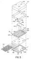
- Fig. 1 is an exploded perspective view of the mattress replacement of the present invention with a plurality of modular zones, including air fluidized zones and air cushions, located within an outer cover, and illustrating controls for the replacement mattress illustrated in diagrammatical form;
- Fig. 2 is an exploded perspective view of an air fluidized seat zone of the present inventions;
- Fig. 3 is an exploded perspective view of another embodiment of the air fluidized seat zone;
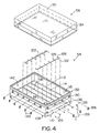
- Fig. 4 is an exploded perspective view of an air fluidized foot zone of the mattress replacement;
- Fig. 5 is an exploded perspective view of another embodiment of the air fluidized foot zone;
- Figs. 6-8 illustrate details of an air wall bladder configured to be located within the mattress surrounding the air fluidized foot zone and seat zone;
- Fig. 9 is a sectional view illustrating details of another embodiment of the present invention which includes a reduced shear head support section;
- Fig. 10 is a sectional view similar to Fig. 9 illustrating movement of air bladders within the head section of the mattress toward a head into the mattress as a head section is pivoted upwardly to an angled position;
- Fig. 11 is a perspective view of another embodiment of a reduced shear head support section for use with the mattress replacement of the present invention; and
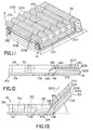
- Figs. 12 and 13 illustrate yet another embodiment of a reduced shear head section of the present invention.
-
- Referring now to the drawings, Fig. 1 illustrates a
mattress replacement apparatus 10 designed for use in any bed frame or other support surface. Themattress 10 includes a bottom cover orbase 12 having abottom surface 14 and asidewall 16.Base 12 is illustratively made from an air impervious, wipeable and cleanable plastic material. Base includes ahead end 23 and afoot end 25. -
Mattress 10 also includes a top air impermeable cover 18 having atop surface 20 and a downwardly extendingsidewall 22.Top cover 18 is secured to base 12 with suitable fasteners such a zipper, snaps, or other coupling mechanism. Aninterior region 24 ofmattress 10 is defined between the base 12 and thecover 18. A plurality of modular mattress components is located within theinterior region 24 ofmattress 10. - An
air support bladder 26 is located withininterior region 24 ofcover 12adjacent head end 23.Air support bladder 26 includes a centerinflatable portion 28 and a pair of spaced apartinflatable tubes 30. A headzone air cushion 32 and a shoulderzone air cushion 34 are located abovesurface 28 ofair support 26. Alumbar cushion 36 is located withininterior region 24 ofbase 12 adjacentshoulder zone cushion 34. A U-shapedair wall bladder 38 havingside sections foot end section 44 is also located withininterior region 24 ofmattress 10 adjacentlumbar cushion 36. - An air fluidized seat section or
zone 48 is located within acenter space 46 defined byair wall bladder 38. Aseat section cover 50 is coupled over the airfluidized seat zone 48. A kneezone air cushion 52 is located withincenter space 46 adjacent airfluidized seat zone 48. An airfluidized foot zone 54 is located withincenter space 46 ofair wall bladder 38 betweenknee zone cushion 52 andend wall 44. Afoot zone cover 56 is coupled over the airfluidized foot zone 54. - An
air blower 58 is configured to blow air through aheat exchanger 60 and into amanifold 62.Manifold 62 is coupled to a plurality ofcontrol valves 64 which control air pressure supplied to various air zones within themattress 10 in a conventional manner. - Air from one of the control valves passes through
tube 66 to connecter 68 which passes through anaperture 70 formed intop cover 18 into anaperture 74 formed inair wall bladder 38.Tube 76 is coupled to connector 68.Tube 76 extends throughside portion 40 ofair wall bladder 38.Tube 76 is coupled to an L-shapedconnector 78 as shown in Fig. 8 to supply air to aninlet 80 of airfluidized seat zone 48 illustrated in Figs. 2 and 3.Connector 78 passes throughaperture 82 formed inside section 40 ofair wall bladder 38. - Another
supply tube 84 extends through anaperture 86 formed inbottom surface 14 ofcover 12 and is coupled to amanifold connector 88.Manifold connector 88 includes a plurality ofoutput lines 90 to supply the variousair zone bladders cover 12 and adjacent zones. - Another
air inlet tube 92 is coupled to L-shapedconnector 94 which extends through anaperture 96 formed in thebottom surface 14 ofcover 12. Theconnector 94 is coupled to anair inlet 98 of airfluidized foot zone 54 as illustrated in Figs. 4 and 5. - Fig. 1 illustrates an air quilt or
blanket 100 designed to fit ontop surface 20 ofimpermeable cover 18. Illustratively, theair blanket 100 is made of a disposable or washable material. Theblanket 100 includes animpermeable layer 102 and an airpermeable layer 104 which is supplied with air through asuitable connector 106.Layer 104 ofair blanket 100 soaks up any drainage from a patient lying on themattress 10 and also supplies air flow throughlayer 104. It is understood that theair flow layer 104 may extend across theentire air blanket 100, if desired. - The
air blanket 100 permits continuous air flow past the patient while maintaining theimpermeable cover 18 to sealinterior region 24 ofmattress 10. Therefore, the mattress components and the air fluidizable medium within the airfluidized seat zone 48 and airfluidized foot zone 54 are not contaminated by fluids from the patient or other contaminants entering themattress 10. - Additional details of the air
fluidized seat zone 48 and cover 50 are illustrated in Figs. 2 and 3. Abase 108 has a generally rectangular shape. A plurality ofsnaps 110 or other fasteners are provided to secure the airfluidized seat zone 48 to adjacent bladders. Aframe 112 is configured to secure adiffuser sheet 114 to the base 108 as best shown in Fig. 3. Thebase 108 andframe 112 are preferably made from a urethane coated nylon twill and are impervious to air.Base 108 includes abottom surface 109 and sidewall 111.Frame 112 is secured around its outer perimeter to an outer perimeter ofbase 108 by ultrasonic or RF welding and by sewing to provide both strength and sealing. A plurality ofbaffles 116 is coupled between thediffuser sheet 114 andbottom surface 109 ofbase 108.Baffles 116 are illustratively welded and sewn tobottom surface 109 and towebs 118 offrame 112 and todiffuser sheet 114.Baffles 116 maintain the plenum height and shape during operation. Thebaffles 116 include a plurality ofapertures 120 to permit air flow throughinlet 80 to pass throughdifruser sheet 114 from theentire plenum 113 which is formed betweenbase 108 andsheet 114. - The
diffuser sheet 114 is illustratively formed from a suitable woven fabric such as a twill weave which permits controlled air flow through thesheet 114.Sheet 114 provides sufficient air flow and pressure drop for movement of the fluidizable medium 115 as discussed below. Illustratively,diffuser sheet 114 is a model number S-1500-SK11 woven material available from Tetko.Diffuser sheet 114 may also be formed from a microporous film made from, for example, polyurethane or other suitable material, which provides sufficient air flow and pressure drop for movement of thefluidizable medium 115. - Metal strips 122 are coupled to
opposite sidewalls 124 offrame 112 bysuitable fasteners 126. The metal strips provide a ground connection for the airfluidized seat zone 48. As illustrated in Fig. 2, one of thefasteners 126 on each side is coupled to a first end of aconductive cable 128 to provide a ground connection. An opposite end of eachcable 128 is coupled to a controller outside themattress 10. - A
sidewall 130 formed from an air impervious material is welded and sewn to the perimeter offrame 112. In the embodiment illustrated in Fig. 2, thesidewall 130 includes atop zipper 132 configured to the coupled to azipper 134 oncover 50.Sidewall 130 in Fig. 2 also includesanchor portions 136 andfastening clips 138 to hold down aflap 140 oftop cover 50. At least atop surface 135 ofcover 50 is formed from an air permeable material. - The
fluidizable medium 115 is loaded into the interior region by unzipping thecover 50 in the embodiment shown in Fig. 2. In another embodiment illustrated in Fig. 3, thesidewall 130 is formed to include anaperture 144 configured to receive acap 146. In the Fig. 3 embodiment, thecover 50 is sewn and welded to thesidewall 130. The fluidizable medium is loaded and drained through theinlet aperture 144. - Illustratively, the
fluidizable medium 115 of the present invention includes both light weight beads and heavy weight beads to provide an overall reduced average weight for the beads. Reduced weight is important since thefluidized zones interior region 142 of thefluidized seat section 48. The firstsize fluidizable medium 115 is illustratively conventional size tiny spheres or beads formed from glass, ceramics, or silicon having an average size between about 50 and about 150 microns, with a specific gravity of about 2.5. These conventional size beads are mixed with beads made of Styrofoam or other suitable material having a size of about 15/1000 to about 20/1000 of an inch (.385-.508 mm), with a specific gravity of about 1. Hollow beads may also be used to reduce weight. Mixture ratios for the different sizes of fluidizable medium can be adjusted depending upon the particular application. By mixing of the beads in this manner, the average weight of thefluidizable medium 115 is less than the average weight of the conventional size beads. - The lighter average weight of the
fluidizable medium 115 of the present invention facilitates transfer of the mattress from one bed frame to another. Themattress 10 can be used on conventional bed frames. The modular components within themattress 10 are replaceable sections. In other words, the airfluidized zones mattress 10 as needed. - Figs. 4 and 5 illustrate details of the air
fluidized foot zone 54 of the present invention. Figs. 4 and 5 include structural components which function in the same or similar manner as components in the airfluidized seat zone 48 of Figs. 2 and 3. Those elements in Figs. 4 and 5 identified by reference numbers the same as in Figs. 2 and 3 perform the same or similar function. The dimensions of therectangular fluidized zone 54 are different from the dimensions ofseat zone 48 in Figs. 2 and 3. In addition, air is supplied into a lower plenum defined betweenbase 108 anddiffuser sheet 112 through aninlet 98 formed inbottom surface 109 ofbase 108. In the embodiment of Fig. 4, thecover 56 is coupled to thesidewall 130 by azipper top cover 56 is sewn and welded tosidewall 130. Thefill inlet aperture 150 is formed inframe 112. A cap orclosure 146 is provided to permit draining and filling of the fluidizable medium 115 into aninterior region 142 of thefoot zone 54. A notchedportion 152 is formed insidewall 130 to accommodate theaperture 150. - In operation, air is supplied to the lower plenum defined between
base 108 anddiffuser sheet 114 through eitherinlet 80 in Figs. 2 and 3 orinlet 98 in Figs. 4 and 5. Thebaffles 116 maintained at plenum height and rectangular shape. Air diffuses throughdiffuser sheet 114 with sufficient air flow velocity and pressure drop to fluidize the fluidizable medium 115 located withininterior region 142. Air can pass out throughfluidized seat zone 48 andfluidized foot zone 54 through top covers 50 and 56, respectively. The top covers 50 and 56 are formed from a air permeable filter material (at least on top surface 135) which permits air flow through thecover covers fluidized seat zone 48 andfoot zone 54 provide excellent support for a patient on themattress 10 and reduce the likelihood of formation of bed sores because of equal distribution of pressure. Fluidizedsections - Additional details of the
air wall bladder 38 are illustrated in Figs. 6-8. Because theimpermeable cover 18 is coupled to thebase 12, there is no way for air flowing throughfluidized seat zone 48 andfluidized foot zone 54 to escape frommattress 10. Therefore, theside portions air wall bladder 38 are formed to includevent slots 160.Tubes 164 are located withinside portions slots 160. Thetubes 164 are fabric tubes having holes to permit air flow into thetubes 164. Thetubes 164 are illustratively RF welded around the boundary ofslots 160.Tubes 164 includeconnectors 162 which extend throughend wall 44 ofair wall bladder 38.Connectors 162 are configured to be coupled totubes 165 as illustrated in Fig. 1.Tubes 165 extend throughapertures 167 intop cover 18. Opposite ends oftubes 165 are coupled to anexhaust fan 166 configured to withdraw air from the interior region ofmattress 10 throughvent slots 160,tubes 164,tubes 165, andfan 166. This provides an exhaust for air entering themattress 10 through thefluidized seat zone 48 andfluidized foot zone 54. It is understood that other air fluidized zones may be included within themattress 10 if desired. - It is understood that the air
impermeable cover 18 may be replaced with an upper low air loss section if desired. The upper low air loss section would permit air passing through thefluidized seat zone 48 andfluidized foot zone 54 to disburse through the low air loss cover without requiring an exhaust mechanism. - Another embodiment of the head section of the present invention is illustrated in Figs. 9 and 10. In this embodiment, the replacement mattress is located on an articulating
deck 170 of a bed. The deck includes ahead section 172, aseat section 174, athigh section 176, and afoot section 178. Figs. 9 and 10 show an alternative embodiment of theknee zone 52 which includes upper andlower chambers bladder sections - The
mattress 10 of Figs. 9 and 10 includes a reduced shearhead support section 184. In the embodiment of Figs. 9 and 10, a first array ofair bladders 186 are coupled together by a web ofmaterial 188 coupled to the end of eachair bladder 186. Illustratively, aweb 188 is located at each end of the array oftubes 186.Tubes 186 are also tethered tobottom surface 14 ofbase 12 by tethers or byair bladders 190 which are coupled tobase 14 and toair bladders 186. The web ofmaterial 188 and the array ofbladders 186 are coupled toair wall bladder 38 bystrap 192.Strap 192 includes afirst end 194 coupled toair wall bladder 38 and asecond end 196 coupled toweb 188. Strap is coupled by suitable fasteners such as snaps. Illustratively, astrap 192 is located on both sides ofmattress 10. A second array ofbladders 198 are located on top ofbladders 186.Bladders 198 are coupled tobladders 186. - As the
head section 172 ofdeck 170 moves upwardly to an elevated position as illustrated in Fig. 10, thebladder 186 adjacentlumbar cushion 36 engages thelumbar cushion 36 and causes the array ofbladders 186 to pivot ontether bladders 190 relative tobottom surface 14 ofbase 12. This causes the array ofbladders 186 to move in the direction of arrow 200 towardhead end 23 ofmattress 10. The top array ofbladders 198 moves with the bottom array ofbladders 186. Illustratively, thebladders head end 23 ofmattress 10 as the head section ofmattress 10 is articulated. This causes reduced shear forces against a patient lying on the mattress. If desired, an anti-shear material can be positioned between the array ofbladders 198 and thetop cover 18 to facilitate sliding movement therebetween. The top array ofbladders 198 may have any desired shape. For instance, the bladders may be generally rectangular as shown in Figs. 9 and 10, or thebladders 198 may be round such as thebladders 186. - Fig. 11 illustrates another embodiment of the reduced shear head section of the present invention. The
head section 202 includes an array oftubes 204 which are tethered to a centralinflated section 206 bytethers 208. Opposite ends oftubes 204 are coupled together by aweb 210 of material secured totubes 204 by suitable technique such as RF welding. A pair of inflated side bolsters 212 is located on opposite sides of centralinflated section 206. The array oftubes 204 is located adjacentlumbar cushion 36. As thehead section 202 is pivoted upwardly in the direction ofarrow 214, thefirst bladder 204 engageslumbar section 36 and causes movement of the array ofbladders 204 in the direction ofarrow 216 to reduce shear forces on a body lying on themattress 10. - Figs. 12 and 13 illustrate another embodiment of the reduced shear head section which is similar to the embodiment illustrated in Fig. 11. In this embodiment, however, a
strap 192 is used to tie thehead section 202 to theair wall bladder 38 as discussed above.First end 194 ofstrap 192 is coupled to theair wall bladder 38 by suitable connectors such as a snap or other suitable connector. Thesecond end 196 ofstrap 192 is coupled to the array ofbladders 204. As thehead section 202 is pivoted upwardly, thebladder 204 engages theair wall bladder 38 or a lumbar cushion, if installed, to cause the array ofbladders 204 to pivot relative tobottom surface 14 ofbase 12. This causesbladders 204 to move in the direction of arrow 200 toward thehead end 23 ofmattress 10.
Claims (28)
- A mattress comprising an outer cover having an interior region and a top support surface a module receiving section located in the interior region of the cover, the module receiving section having a first coupling portion in fluid communication with an air supply, and,
an air fluidized module having a first chamber containing a fluidizable material, a second chamber, a second coupling portion coupled to the module in fluid communication with the second chamber, and an air permeable sheet located between the first and second chambers, the air fluidized module being configured to be located in the module receiving section, and the first and second coupling portion being configured to be coupled together to provide fluid communication between the air supply and the second chamber so that air from the air supply passes into the second chamber and through the air permeable sheet to fluidize the fluidizable material in the first chamber. - The mattress of Claim 1, further comprising a head support section located adjacent the module receiving section, the head support section having a shear-reducing support surface.
- The mattress of Claim 2, wherein the head support section is coupled for movement relative to the module receiving section upon articulation of a deck on which the mattress is located.
- The mattress of Claim 1, further comprising a head support section located adjacent the module receiving section in the interior region of the cover, the head support section having a base portion and a shear reducing support surface pivotably coupled to the base portion, and a coupler connected between the module receiving section and the head support section so that the head support section moves toward the head end of the mattress as the head support section is moved to an elevated position relative to the module receiving section.
- The mattress of any one of Claims 2 to 4, wherein the head support section includes at least one air cushion.
- The mattress of Claim 5 portion as dependent on Claim 4, wherein the head support section include a set of air cushions pivotably coupled to the base.
- The mattress of Claim 6, further comprising a second set of air cushions located above the air cushions pivotably coupled to the base portion.
- The mattress of any preceding claim, wherein the module receiving section also includes an inflatable non-fluidized module connected to the air supply.
- The mattress of any one of Claims 1 to 7, further comprising a non-fluidized module including a flexible air impermeable outer wall defining an interior region and a third coupling portion coupled to the outer wall in fluid communication with the interior region of the non-fluidized module, the fluidized module and the non-fluidized module being interchangeable in the module receiving section with the first coupling portion being configured to couple alternatively with one of the second coupling portion of the fluidized module and the third coupling portion of the non-fluidized module.
- The mattress of any preceding claim, further comprising a manifold located between the air supply and the first coupling portion of the module receiving section, and a control valve to control the rate of air supply to the first coupling portion.
- The mattress of Claim 10, further comprising an inflatable air cushion located adjacent the air fluidized module in the interior region of the cover, the air cushion being coupled to the air supply through the manifold.
- The mattress of any preceding claim, wherein the air fluidized module has a top surface which is air permeable.
- The mattress of any preceding claim, wherein the air fluidized module includes a base formed from an air impermeable material, the base including a bottom surface and a side wall configured to define an interior region, an air permeable diffuser located within the interior region of the base, the diffuser being coupled to the side wall of the base to define the first chamber and the second chamber, an air permeable top surface coupled to the base, a plurality of baffles coupled to the base, the baffles being located in the second chamber.
- A mattress as claimed in Claim 13, wherein the first fluidized chamber includes an access port provided for removing and inserting the fluidizable material.
- A mattress as claimed in Claim 13 or Claim 14, wherein a top cover including the air permeable top surface and a side wall extending from the top surface are provided, the side wall of the top cover being coupled to the side wall of the base.
- A mattress as claimed in Claim 15, wherein the side wall of the top cover includes a first zipper half and the side wall of the base includes a second zipper half, the first zipper half and second zipper half being coupled to attach the top cover the base.
- A mattress as claimed in Claim 16, wherein the top cover is removable from the base to provide access to the fluidizable material.
- A mattress as claimed in any one of Claims 13 to 17, wherein at least one grounding strip is coupled to the side wall of the base.
- A mattress as claimed in Claim 18, wherein a conductive cable is coupled to the at least one grounding strip to provide a ground connection for the support module.
- A mattress as claimed in any one of Claims 13 to 19, wherein the base includes a bottom surface, a frame, and a separate side wall coupled together to form the base.
- A mattress as claimed in any one of Claims 13 to 19 wherein a frame is coupled to the side wall of the base, the frame being configured to support the diffuser.
- A mattress as claimed in either Claim 20 or Claim 21, wherein the frame includes a plurality of webs extending between opposite sides of the frame, the baffles being coupled between the webs and the bottom surface of the base.
- A mattress as claimed in Claim 22, wherein the baffles are ultrasonically welded and sewn to the bottom surface, the webs of the frame, and the diffuser sheet.
- A mattress as claimed in any one of Claims 13 to 23, wherein the baffles are each formed to include a plurality of apertures to permit air flow through the second chamber.
- A mattress as claimed in any one of Claims 13 to 24, wherein a plurality of fasteners is coupled to the side wall of the base, the fasteners being configured to secure the support module within the mattress.
- A mattress as claimed in any of the preceding claims, wherein a plurality of air cushions are also located within the interior region of the cover.
- A mattress as claimed in Claim 26, wherein the plurality of air cushions are air impermeable support cushions.
- A mattress as claimed in any of the preceding claims, wherein an air quilt is located on the top surface of the cover.
Priority Applications (1)
| Application Number | Priority Date | Filing Date | Title |
|---|---|---|---|
| EP07075452A EP1820424A3 (en) | 1997-10-24 | 1998-10-23 | Mattress having air fluidized sections |
Applications Claiming Priority (3)
| Application Number | Priority Date | Filing Date | Title |
|---|---|---|---|
| US6311897P | 1997-10-24 | 1997-10-24 | |
| US63118P | 1997-10-24 | ||
| EP98953946A EP1024733B1 (en) | 1997-10-24 | 1998-10-23 | Mattress having air fluidized sections |
Related Parent Applications (1)
| Application Number | Title | Priority Date | Filing Date |
|---|---|---|---|
| EP98953946A Division EP1024733B1 (en) | 1997-10-24 | 1998-10-23 | Mattress having air fluidized sections |
Related Child Applications (1)
| Application Number | Title | Priority Date | Filing Date |
|---|---|---|---|
| EP07075452A Division EP1820424A3 (en) | 1997-10-24 | 1998-10-23 | Mattress having air fluidized sections |
Publications (3)
| Publication Number | Publication Date |
|---|---|
| EP1238606A2 true EP1238606A2 (en) | 2002-09-11 |
| EP1238606A3 EP1238606A3 (en) | 2002-10-23 |
| EP1238606B1 EP1238606B1 (en) | 2007-06-13 |
Family
ID=22047044
Family Applications (3)
| Application Number | Title | Priority Date | Filing Date |
|---|---|---|---|
| EP98953946A Expired - Lifetime EP1024733B1 (en) | 1997-10-24 | 1998-10-23 | Mattress having air fluidized sections |
| EP02076243A Expired - Lifetime EP1238606B1 (en) | 1997-10-24 | 1998-10-23 | Mattress having air fluidized sections |
| EP07075452A Withdrawn EP1820424A3 (en) | 1997-10-24 | 1998-10-23 | Mattress having air fluidized sections |
Family Applications Before (1)
| Application Number | Title | Priority Date | Filing Date |
|---|---|---|---|
| EP98953946A Expired - Lifetime EP1024733B1 (en) | 1997-10-24 | 1998-10-23 | Mattress having air fluidized sections |
Family Applications After (1)
| Application Number | Title | Priority Date | Filing Date |
|---|---|---|---|
| EP07075452A Withdrawn EP1820424A3 (en) | 1997-10-24 | 1998-10-23 | Mattress having air fluidized sections |
Country Status (11)
| Country | Link |
|---|---|
| US (4) | US6351862B1 (en) |
| EP (3) | EP1024733B1 (en) |
| JP (1) | JP2001520900A (en) |
| KR (1) | KR20010031196A (en) |
| CN (1) | CN1105538C (en) |
| AT (2) | ATE230950T1 (en) |
| AU (1) | AU1118799A (en) |
| CA (1) | CA2308326A1 (en) |
| CZ (1) | CZ20001429A3 (en) |
| DE (2) | DE69837943T2 (en) |
| WO (1) | WO1999021457A1 (en) |
Families Citing this family (31)
| Publication number | Priority date | Publication date | Assignee | Title |
|---|---|---|---|---|
| EP1024733B1 (en) * | 1997-10-24 | 2003-01-15 | Hill-Rom Services, Inc. | Mattress having air fluidized sections |
| EP1194106A1 (en) * | 1999-07-06 | 2002-04-10 | Hill-Rom Services, Inc. | Mattress assembly |
| US6689077B2 (en) | 1999-08-10 | 2004-02-10 | Reza R. Dabir | Apparatus and method for pressure management having temperature controlled air flow |
| EP1257241A2 (en) * | 2000-02-25 | 2002-11-20 | Hill-Rom Services, Inc. | Air fluidized bladders for a bed |
| GB0102655D0 (en) * | 2001-02-02 | 2001-03-21 | Worlds Apart Ltd | Sleeping apparatus |
| ATE415840T1 (en) * | 2002-02-28 | 2008-12-15 | Gaymar Ind Inc | SELF-ADJUSTING UPHOLSTERY DEVICE |
| WO2004014193A1 (en) * | 2002-08-08 | 2004-02-19 | Hill-Rom Services, Inc. | Mattress |
| AU2003287697A1 (en) * | 2002-11-08 | 2004-06-03 | Barnes-Jewish Hospital | Uncoupled collagen synthesis and degradation assays |
| US20050177951A1 (en) * | 2004-02-17 | 2005-08-18 | Zhu Guifang | Inflatable air mattress |
| US7469436B2 (en) * | 2004-04-30 | 2008-12-30 | Hill-Rom Services, Inc. | Pressure relief surface |
| EP2250988A3 (en) * | 2004-04-30 | 2011-11-30 | Hill-Rom Services, Inc. | Patient support with motion monitor device |
| US7543583B2 (en) * | 2004-07-28 | 2009-06-09 | Hill-Rom Services, Inc. | Forced air vent in siderail |
| US8470012B2 (en) | 2004-09-08 | 2013-06-25 | Arizant Healthcare Inc. | Inflatable convective pad for surgery |
| US7219380B2 (en) * | 2005-04-22 | 2007-05-22 | R&D Products, Llc | Multicompartmented air mattress |
| AU2006269277B2 (en) * | 2005-07-08 | 2012-02-16 | Hill-Rom, Inc. | Patient support |
| JP5231222B2 (en) * | 2005-07-08 | 2013-07-10 | ヒル−ロム サービシーズ,インコーポレイティド | Patient support control unit |
| NZ576819A (en) * | 2006-10-16 | 2011-02-25 | A H Beard Pty Ltd | Air fillable mattress |
| WO2008131608A1 (en) * | 2007-04-28 | 2008-11-06 | Enlanda | Combined mattress |
| US20090144903A1 (en) * | 2007-12-06 | 2009-06-11 | Delvaux Andrew B | Cpr facilitating mattress |
| US20110099722A1 (en) * | 2009-09-02 | 2011-05-05 | David Michael Moret | Mattresses with reinforcement inserts and densified stitch zones |
| CN101926714B (en) * | 2010-07-23 | 2013-04-10 | 任晓宇 | Multifunctional nursing bed for preventing bedsores |
| GB201017830D0 (en) * | 2010-10-21 | 2010-12-01 | Trinity College Dublin | Pneumatic mattress |
| US20130081205A1 (en) * | 2011-09-30 | 2013-04-04 | Michael M. Frondorf | Person support surface |
| GB201207839D0 (en) * | 2012-05-03 | 2012-06-20 | Psp Technology Ltd | Pneumatic mattress |
| US9060908B2 (en) | 2013-01-21 | 2015-06-23 | Hill-Rom Services, Inc. | Varying depth fluidized bed |
| US20140259427A1 (en) * | 2013-03-13 | 2014-09-18 | Hill-Rom Services, Inc. | Fabric diffuser for fluidized bed |
| US10238560B2 (en) | 2013-03-13 | 2019-03-26 | Hill-Rom Services, Inc. | Air fluidized therapy bed having pulmonary therapy |
| US9456701B2 (en) | 2014-06-13 | 2016-10-04 | Aeris Technology LLC | Valve assembly for controlling fluid communication between fluid chambers, inflatable device, and method |
| CN107854251A (en) * | 2017-12-13 | 2018-03-30 | 泰兴市汇辰过滤器制造有限公司 | A kind of vessel is used for the lifesaving bed of rescue |
| US11389120B2 (en) | 2019-05-30 | 2022-07-19 | Hill-Rom Services, Inc. | Mattress having selectable patient weight valve, inductive power, and a digital x-ray cassette |
| WO2022061082A1 (en) * | 2020-09-18 | 2022-03-24 | Hill-Rom Services, Inc. | Therapeutic mattress overlay including rotation and moisture management |
Citations (5)
| Publication number | Priority date | Publication date | Assignee | Title |
|---|---|---|---|---|
| US5029352A (en) * | 1988-12-20 | 1991-07-09 | Ssi Medical Services, Inc. | Dual support surface patient support |
| US5036559A (en) * | 1988-12-20 | 1991-08-06 | SSI Medical Sevices, Inc. | Method of dual mode patient support |
| WO1995031920A1 (en) * | 1994-05-25 | 1995-11-30 | Egerton Hospital Equipment Limited | Improvements in and relating to low air-loss mattresses |
| WO1996033641A1 (en) * | 1995-04-25 | 1996-10-31 | Kinetic Concepts, Inc. | Air bed with fluidized bead surface and related methods |
| US5623736A (en) * | 1994-12-09 | 1997-04-29 | Suport Systems, International | Modular inflatable/air fluidized bed |
Family Cites Families (73)
| Publication number | Priority date | Publication date | Assignee | Title |
|---|---|---|---|---|
| US433905A (en) * | 1890-08-05 | Theodor muller | ||
| US2547840A (en) * | 1949-04-01 | 1951-04-03 | William B Smith | Sectional mattress |
| DE1606128U (en) * | 1950-01-09 | 1950-05-11 | Wetzell Gummiwerke A G | AIR MATTRESS. |
| FR2265347B1 (en) * | 1974-03-27 | 1979-06-15 | Poudres & Explosifs Ste Nale | |
| US3978530A (en) * | 1975-11-21 | 1976-09-07 | Amarantos John G | Air inflatable bed-like device with adjustable back support |
| US4483029A (en) | 1981-08-10 | 1984-11-20 | Support Systems International, Inc. | Fluidized supporting apparatus |
| US4425676A (en) * | 1982-03-09 | 1984-01-17 | Crane Robert L | Cushion to reduce the incidence of decubitus ulcers in immobilized patients |
| FR2523841B1 (en) | 1982-03-25 | 1985-10-25 | Lacoste Francois | FLUIDIZED BED FOR THERAPEUTIC USE |
| US4644597A (en) * | 1983-05-09 | 1987-02-24 | Dynatech, Inc. | Air mattress with pressure relief valve |
| JPS60116351A (en) * | 1983-11-30 | 1985-06-22 | 富士電機株式会社 | Beads flowing type bed apparatus |
| US4518203A (en) * | 1983-12-02 | 1985-05-21 | White Kirk E | Convertible cushion furniture |
| US4879777A (en) | 1984-01-17 | 1989-11-14 | Support Systems International, Inc. | Fluidized patient support system |
| US4564965A (en) | 1984-01-17 | 1986-01-21 | Support Systems International, Inc. | Fluidized patient support system |
| US4776050A (en) | 1984-01-17 | 1988-10-11 | Support Systems International, Inc. | Fluidized patient support system |
| US4672699A (en) | 1984-01-17 | 1987-06-16 | Support Systems International, Inc. | Fluidized patient support system with side rail assembly |
| US4609854A (en) * | 1985-02-01 | 1986-09-02 | Fuji Electric Company Ltd. | Control device for a hospital bed |
| US4637083A (en) | 1985-03-13 | 1987-01-20 | Support Systems International, Inc. | Fluidized patient support apparatus |
| US4638519A (en) | 1985-04-04 | 1987-01-27 | Air Plus, Inc. | Fluidized hospital bed |
| US4685163A (en) * | 1985-04-16 | 1987-08-11 | Quillen Jeffrey B | Recliner for medical convalescence |
| DE3687060T2 (en) * | 1985-05-10 | 1993-05-27 | Mediscus Prod Ltd | PATIENT ASSISTANCE DEVICE. |
| JPS61290953A (en) * | 1985-06-19 | 1986-12-20 | 富士電機株式会社 | Body support |
| US4768250A (en) * | 1985-07-30 | 1988-09-06 | Fuji Electric Co., Ltd. | Fluidized bead bed |
| DE3774525D1 (en) * | 1986-04-09 | 1991-12-19 | Lepinoy Ind | METHOD, DEVICE AND UPHOLSTERED PRODUCT FOR SUPPORTING AN OBJECT. |
| US4803744A (en) | 1987-05-19 | 1989-02-14 | Hill-Rom Company, Inc. | Inflatable bed |
| US5586348A (en) * | 1987-06-24 | 1996-12-24 | Ahlstrom Consumer Products Ltd. | Air mattress and method for adjusting it |
| NL8800792A (en) * | 1988-03-29 | 1989-10-16 | Redactron Bv | METHOD AND APPARATUS FOR EXTRACTING MOISTURE FROM ONE OR MORE BODIES |
| US4953247A (en) * | 1988-05-09 | 1990-09-04 | Hasty Charles E | Air-operated body support device |
| US5249318A (en) * | 1988-05-24 | 1993-10-05 | Loadsman Gerald H | Air support cushion |
| US5621934A (en) * | 1988-06-22 | 1997-04-22 | A. Ahlstrom Corporation | Mattress |
| US5008965A (en) | 1988-07-11 | 1991-04-23 | Kinetic Concepts, Inc. | Fluidized bead bed |
| US4998310A (en) * | 1988-10-12 | 1991-03-12 | Olson Robert V | Breakdown air mattress assembly |
| US4935635A (en) * | 1988-12-09 | 1990-06-19 | Harra Dale G O | System for measuring objects in three dimensions |
| US4967431A (en) | 1988-12-20 | 1990-11-06 | SSI Medical Servies, Inc. | Fluidized bed with modular fluidizable portion |
| US4914760A (en) | 1988-12-20 | 1990-04-10 | Ssi Medical Services, Inc. | Fluidized bed with collapsible side |
| US4951335A (en) * | 1989-06-05 | 1990-08-28 | Donan Marketing Corporation | Mattress assembly |
| US5020176A (en) * | 1989-10-20 | 1991-06-04 | Angel Echevarria Co., Inc. | Control system for fluid-filled beds |
| US5105487A (en) | 1990-12-17 | 1992-04-21 | Ssi Medical Services, Inc. | Apparatus for patient elevation above a fluidized surface |
| US5165141A (en) * | 1991-01-11 | 1992-11-24 | Ssi Medical Services, Inc. | Spring loaded heavy duty caster system for supporting a fluidized patient support system |
| FR2682293B1 (en) * | 1991-10-11 | 1994-03-11 | Georges Roux | FLUIDIZED MEDICAL BED PROVIDED WITH A DEVICE FOR EVACUATING ITS CONTAMINATED GRANULAR CONSTITUENTS. |
| CN2131385Y (en) * | 1992-05-15 | 1993-05-05 | 杨建� | Anti-bed sore air-filling mattress |
| US5325551A (en) * | 1992-06-16 | 1994-07-05 | Stryker Corporation | Mattress for retarding development of decubitus ulcers |
| US5267364A (en) * | 1992-08-11 | 1993-12-07 | Kinetic Concepts, Inc. | Therapeutic wave mattress |
| US5402542A (en) | 1993-04-22 | 1995-04-04 | Ssi Medical Services, Inc. | Fluidized patient support with improved temperature control |
| US5367728A (en) * | 1993-04-23 | 1994-11-29 | Chang; Ching-Lung | Adjustable ventilation mattress |
| US5345630A (en) * | 1993-07-15 | 1994-09-13 | Jack Healy | Quick inflatable air mattress |
| AT400222B (en) * | 1993-10-27 | 1995-11-27 | Schwarz Zoehrer Sabine | Lounger for a toddler |
| US5539943A (en) | 1994-03-08 | 1996-07-30 | Ssi Medical Services, Inc. | Apparatus and method for percussion of fluidized support surface |
| US5537701A (en) * | 1994-03-15 | 1996-07-23 | Maxwell Products, Inc. | Adjustable articulated bed |
| US5493742A (en) * | 1994-05-10 | 1996-02-27 | Lake Medical Products, Inc. | Ventilating air mattress with an inflating quilted pad |
| US5560056A (en) * | 1995-01-27 | 1996-10-01 | Tai; Tsai-Ting | Multiple-purpose hammock, chair, and float type apparatus |
| CN2231061Y (en) * | 1995-03-03 | 1996-07-17 | 张崇泰 | Air bed |
| US6721979B1 (en) * | 1995-04-25 | 2004-04-20 | Kci Licensing, Inc. | Air bed with fluidized bead surface and related methods |
| TW270970B (en) * | 1995-04-26 | 1996-02-21 | Ehara Seisakusho Kk | Fluidized bed combustion device |
| US5682631A (en) * | 1995-08-04 | 1997-11-04 | Hill-Rom, Inc. | Bed having a reduced-shear pivot and step deck combination |
| US5991949A (en) * | 1995-08-15 | 1999-11-30 | Foamex L.P. | Hoseless air bed |
| US5655239A (en) * | 1996-09-20 | 1997-08-12 | Joerns Healthcare, Inc. | Cellular air loss mattress system |
| US5815865A (en) | 1995-11-30 | 1998-10-06 | Sleep Options, Inc. | Mattress structure |
| US5647079A (en) * | 1996-03-20 | 1997-07-15 | Hill-Rom, Inc. | Inflatable patient support surface system |
| US5699570A (en) * | 1996-06-14 | 1997-12-23 | Span-America Medical Systems, Inc. | Pressure relief valve vent line mattress system and method |
| US5873137A (en) * | 1996-06-17 | 1999-02-23 | Medogar Technologies | Pnuematic mattress systems |
| US5966763A (en) * | 1996-08-02 | 1999-10-19 | Hill-Rom, Inc. | Surface pad system for a surgical table |
| US5680662A (en) * | 1996-09-09 | 1997-10-28 | Veritas Enterprises, Inc. | Cushioning mattress for reducing shear and friction |
| GB9618796D0 (en) * | 1996-09-09 | 1996-10-23 | Pegasus Airwave Ltd | Mattress cover |
| US5781943A (en) * | 1997-03-13 | 1998-07-21 | Moenning; Stephen P. | Medical table and method for moving a patient from a first position to a second position |
| US5855207A (en) * | 1997-05-29 | 1999-01-05 | Moenning; Stephen P. | Medical table assembly having a restrainment apparatus mounted thereto and an associated method of immobilizing object |
| US6192537B1 (en) * | 1997-06-27 | 2001-02-27 | Sakae Miki | Semi-fluid based body support system |
| US6016581A (en) * | 1997-06-27 | 2000-01-25 | Miki; Sakae | Semi-fluid mattress |
| US5740573A (en) * | 1997-07-15 | 1998-04-21 | Boyd; Dennis | Air bed with circumferential belt |
| US6006379A (en) * | 1997-08-04 | 1999-12-28 | Patmark Company, Inc. | Articulating bed frame |
| EP1024733B1 (en) * | 1997-10-24 | 2003-01-15 | Hill-Rom Services, Inc. | Mattress having air fluidized sections |
| US6073289A (en) * | 1997-12-18 | 2000-06-13 | Hill-Rom, Inc. | Air fluidized bed |
| US5966762A (en) * | 1998-07-01 | 1999-10-19 | Wu; Shan-Chieh | Air mattress for modulating ridden positions |
| EP1257241A2 (en) * | 2000-02-25 | 2002-11-20 | Hill-Rom Services, Inc. | Air fluidized bladders for a bed |
-
1998
- 1998-10-23 EP EP98953946A patent/EP1024733B1/en not_active Expired - Lifetime
- 1998-10-23 AU AU11187/99A patent/AU1118799A/en not_active Abandoned
- 1998-10-23 CA CA002308326A patent/CA2308326A1/en not_active Abandoned
- 1998-10-23 WO PCT/US1998/022526 patent/WO1999021457A1/en not_active Application Discontinuation
- 1998-10-23 CZ CZ20001429A patent/CZ20001429A3/en unknown
- 1998-10-23 JP JP2000517629A patent/JP2001520900A/en active Pending
- 1998-10-23 EP EP02076243A patent/EP1238606B1/en not_active Expired - Lifetime
- 1998-10-23 CN CN98810494A patent/CN1105538C/en not_active Expired - Fee Related
- 1998-10-23 DE DE69837943T patent/DE69837943T2/en not_active Expired - Fee Related
- 1998-10-23 AT AT98953946T patent/ATE230950T1/en not_active IP Right Cessation
- 1998-10-23 AT AT02076243T patent/ATE364339T1/en not_active IP Right Cessation
- 1998-10-23 EP EP07075452A patent/EP1820424A3/en not_active Withdrawn
- 1998-10-23 DE DE69810802T patent/DE69810802T2/en not_active Expired - Lifetime
- 1998-10-23 KR KR1020007004139A patent/KR20010031196A/en not_active Application Discontinuation
- 1998-10-23 US US09/177,772 patent/US6351862B1/en not_active Expired - Fee Related
-
2002
- 2002-03-04 US US10/090,722 patent/US6564412B2/en not_active Expired - Lifetime
-
2003
- 2003-05-19 US US10/440,905 patent/US6735801B2/en not_active Expired - Fee Related
-
2004
- 2004-03-19 US US10/804,905 patent/US20040172764A1/en not_active Abandoned
Patent Citations (5)
| Publication number | Priority date | Publication date | Assignee | Title |
|---|---|---|---|---|
| US5029352A (en) * | 1988-12-20 | 1991-07-09 | Ssi Medical Services, Inc. | Dual support surface patient support |
| US5036559A (en) * | 1988-12-20 | 1991-08-06 | SSI Medical Sevices, Inc. | Method of dual mode patient support |
| WO1995031920A1 (en) * | 1994-05-25 | 1995-11-30 | Egerton Hospital Equipment Limited | Improvements in and relating to low air-loss mattresses |
| US5623736A (en) * | 1994-12-09 | 1997-04-29 | Suport Systems, International | Modular inflatable/air fluidized bed |
| WO1996033641A1 (en) * | 1995-04-25 | 1996-10-31 | Kinetic Concepts, Inc. | Air bed with fluidized bead surface and related methods |
Also Published As
| Publication number | Publication date |
|---|---|
| US6564412B2 (en) | 2003-05-20 |
| EP1024733A1 (en) | 2000-08-09 |
| EP1820424A2 (en) | 2007-08-22 |
| AU1118799A (en) | 1999-05-17 |
| EP1820424A3 (en) | 2008-04-23 |
| KR20010031196A (en) | 2001-04-16 |
| US20040172764A1 (en) | 2004-09-09 |
| US20030196271A1 (en) | 2003-10-23 |
| EP1024733B1 (en) | 2003-01-15 |
| ATE364339T1 (en) | 2007-07-15 |
| DE69837943D1 (en) | 2007-07-26 |
| WO1999021457A1 (en) | 1999-05-06 |
| ATE230950T1 (en) | 2003-02-15 |
| US6735801B2 (en) | 2004-05-18 |
| JP2001520900A (en) | 2001-11-06 |
| CN1277544A (en) | 2000-12-20 |
| US6351862B1 (en) | 2002-03-05 |
| DE69810802T2 (en) | 2003-11-06 |
| US20020083529A1 (en) | 2002-07-04 |
| EP1238606A3 (en) | 2002-10-23 |
| CA2308326A1 (en) | 1999-05-06 |
| CN1105538C (en) | 2003-04-16 |
| CZ20001429A3 (en) | 2001-11-14 |
| EP1238606B1 (en) | 2007-06-13 |
| DE69810802D1 (en) | 2003-02-20 |
| DE69837943T2 (en) | 2007-12-20 |
Similar Documents
| Publication | Publication Date | Title |
|---|---|---|
| US6351862B1 (en) | Mattress replacement having air fluidized sections | |
| EP0569058B1 (en) | Patient support systems | |
| CA2355964C (en) | Mattress assembly | |
| US6694555B2 (en) | Air fluidized bladders for a bed | |
| US5029352A (en) | Dual support surface patient support | |
| US5647079A (en) | Inflatable patient support surface system | |
| US4914760A (en) | Fluidized bed with collapsible side | |
| US4967431A (en) | Fluidized bed with modular fluidizable portion | |
| US20090217460A1 (en) | Patient support | |
| US6158070A (en) | Coverlet for an air bed | |
| EP2286783A2 (en) | Fluidized bed | |
| MXPA00003749A (en) | Mattress having air fluidized sections | |
| EP1139966B1 (en) | Fluidized bead bed with inflatable bead diffuser | |
| EP0569056A2 (en) | Patient support system and method | |
| EP0569057A2 (en) | Patient support systems |
Legal Events
| Date | Code | Title | Description |
|---|---|---|---|
| PUAI | Public reference made under article 153(3) epc to a published international application that has entered the european phase |
Free format text: ORIGINAL CODE: 0009012 |
|
| PUAL | Search report despatched |
Free format text: ORIGINAL CODE: 0009013 |
|
| 17P | Request for examination filed |
Effective date: 20020329 |
|
| AC | Divisional application: reference to earlier application |
Ref document number: 1024733 Country of ref document: EP |
|
| AK | Designated contracting states |
Kind code of ref document: A2 Designated state(s): AT BE CH DE ES FR GB IE IT LI LU NL SE |
|
| AK | Designated contracting states |
Kind code of ref document: A3 Designated state(s): AT BE CH DE ES FR GB IE IT LI LU NL SE |
|
| RIN1 | Information on inventor provided before grant (corrected) |
Inventor name: ROMANO, JAMES J. Inventor name: NOVACK, ROBERT C. Inventor name: DELK, DANA H. Inventor name: HENLEY, ALAN W. |
|
| RIN1 | Information on inventor provided before grant (corrected) |
Inventor name: ROMANO, JAMES J. Inventor name: NOVACK, ROBERT C. Inventor name: HENLEY, ALAN W. Inventor name: DELK, DANA H. |
|
| AKX | Designation fees paid |
Designated state(s): AT BE CH DE ES FR GB IE IT LI LU NL SE |
|
| GRAP | Despatch of communication of intention to grant a patent |
Free format text: ORIGINAL CODE: EPIDOSNIGR1 |
|
| RIN1 | Information on inventor provided before grant (corrected) |
Inventor name: HENLEY, ALAN W. Inventor name: NOVACK, ROBERT C. Inventor name: DELK, DANA H. Inventor name: ROMANO, JAMES J. |
|
| GRAS | Grant fee paid |
Free format text: ORIGINAL CODE: EPIDOSNIGR3 |
|
| GRAA | (expected) grant |
Free format text: ORIGINAL CODE: 0009210 |
|
| AC | Divisional application: reference to earlier application |
Ref document number: 1024733 Country of ref document: EP Kind code of ref document: P |
|
| AK | Designated contracting states |
Kind code of ref document: B1 Designated state(s): AT BE CH DE ES FR GB IE IT LI LU NL SE |
|
| PG25 | Lapsed in a contracting state [announced via postgrant information from national office to epo] |
Ref country code: LI Free format text: LAPSE BECAUSE OF FAILURE TO SUBMIT A TRANSLATION OF THE DESCRIPTION OR TO PAY THE FEE WITHIN THE PRESCRIBED TIME-LIMIT Effective date: 20070613 Ref country code: CH Free format text: LAPSE BECAUSE OF FAILURE TO SUBMIT A TRANSLATION OF THE DESCRIPTION OR TO PAY THE FEE WITHIN THE PRESCRIBED TIME-LIMIT Effective date: 20070613 |
|
| REG | Reference to a national code |
Ref country code: GB Ref legal event code: FG4D |
|
| REG | Reference to a national code |
Ref country code: CH Ref legal event code: EP |
|
| REG | Reference to a national code |
Ref country code: IE Ref legal event code: FG4D |
|
| REF | Corresponds to: |
Ref document number: 69837943 Country of ref document: DE Date of ref document: 20070726 Kind code of ref document: P |
|
| PG25 | Lapsed in a contracting state [announced via postgrant information from national office to epo] |
Ref country code: SE Free format text: LAPSE BECAUSE OF FAILURE TO SUBMIT A TRANSLATION OF THE DESCRIPTION OR TO PAY THE FEE WITHIN THE PRESCRIBED TIME-LIMIT Effective date: 20070913 |
|
| ET | Fr: translation filed | ||
| PG25 | Lapsed in a contracting state [announced via postgrant information from national office to epo] |
Ref country code: AT Free format text: LAPSE BECAUSE OF FAILURE TO SUBMIT A TRANSLATION OF THE DESCRIPTION OR TO PAY THE FEE WITHIN THE PRESCRIBED TIME-LIMIT Effective date: 20070613 |
|
| NLV1 | Nl: lapsed or annulled due to failure to fulfill the requirements of art. 29p and 29m of the patents act | ||
| REG | Reference to a national code |
Ref country code: CH Ref legal event code: PL |
|
| PG25 | Lapsed in a contracting state [announced via postgrant information from national office to epo] |
Ref country code: BE Free format text: LAPSE BECAUSE OF FAILURE TO SUBMIT A TRANSLATION OF THE DESCRIPTION OR TO PAY THE FEE WITHIN THE PRESCRIBED TIME-LIMIT Effective date: 20070613 |
|
| PG25 | Lapsed in a contracting state [announced via postgrant information from national office to epo] |
Ref country code: NL Free format text: LAPSE BECAUSE OF FAILURE TO SUBMIT A TRANSLATION OF THE DESCRIPTION OR TO PAY THE FEE WITHIN THE PRESCRIBED TIME-LIMIT Effective date: 20070613 Ref country code: ES Free format text: LAPSE BECAUSE OF FAILURE TO SUBMIT A TRANSLATION OF THE DESCRIPTION OR TO PAY THE FEE WITHIN THE PRESCRIBED TIME-LIMIT Effective date: 20070924 |
|
| PGFP | Annual fee paid to national office [announced via postgrant information from national office to epo] |
Ref country code: DE Payment date: 20071130 Year of fee payment: 10 |
|
| PLBE | No opposition filed within time limit |
Free format text: ORIGINAL CODE: 0009261 |
|
| STAA | Information on the status of an ep patent application or granted ep patent |
Free format text: STATUS: NO OPPOSITION FILED WITHIN TIME LIMIT |
|
| PG25 | Lapsed in a contracting state [announced via postgrant information from national office to epo] |
Ref country code: IT Free format text: LAPSE BECAUSE OF FAILURE TO SUBMIT A TRANSLATION OF THE DESCRIPTION OR TO PAY THE FEE WITHIN THE PRESCRIBED TIME-LIMIT Effective date: 20070613 |
|
| PGFP | Annual fee paid to national office [announced via postgrant information from national office to epo] |
Ref country code: GB Payment date: 20071029 Year of fee payment: 10 |
|
| 26N | No opposition filed |
Effective date: 20080314 |
|
| PG25 | Lapsed in a contracting state [announced via postgrant information from national office to epo] |
Ref country code: IE Free format text: LAPSE BECAUSE OF NON-PAYMENT OF DUE FEES Effective date: 20071023 |
|
| PGFP | Annual fee paid to national office [announced via postgrant information from national office to epo] |
Ref country code: FR Payment date: 20081018 Year of fee payment: 11 |
|
| GBPC | Gb: european patent ceased through non-payment of renewal fee |
Effective date: 20081023 |
|
| PG25 | Lapsed in a contracting state [announced via postgrant information from national office to epo] |
Ref country code: LU Free format text: LAPSE BECAUSE OF NON-PAYMENT OF DUE FEES Effective date: 20071023 Ref country code: DE Free format text: LAPSE BECAUSE OF NON-PAYMENT OF DUE FEES Effective date: 20090501 |
|
| PG25 | Lapsed in a contracting state [announced via postgrant information from national office to epo] |
Ref country code: GB Free format text: LAPSE BECAUSE OF NON-PAYMENT OF DUE FEES Effective date: 20081023 |
|
| REG | Reference to a national code |
Ref country code: FR Ref legal event code: ST Effective date: 20100630 |
|
| PG25 | Lapsed in a contracting state [announced via postgrant information from national office to epo] |
Ref country code: FR Free format text: LAPSE BECAUSE OF NON-PAYMENT OF DUE FEES Effective date: 20091102 |