EP1238916A1 - Process for shirnk sleeveing bottle with a handle - Google Patents
Process for shirnk sleeveing bottle with a handle Download PDFInfo
- Publication number
- EP1238916A1 EP1238916A1 EP01200914A EP01200914A EP1238916A1 EP 1238916 A1 EP1238916 A1 EP 1238916A1 EP 01200914 A EP01200914 A EP 01200914A EP 01200914 A EP01200914 A EP 01200914A EP 1238916 A1 EP1238916 A1 EP 1238916A1
- Authority
- EP
- European Patent Office
- Prior art keywords
- bottle
- sleeve
- handle
- cut
- out region
- Prior art date
- Legal status (The legal status is an assumption and is not a legal conclusion. Google has not performed a legal analysis and makes no representation as to the accuracy of the status listed.)
- Granted
Links
Images


Classifications
-
- B—PERFORMING OPERATIONS; TRANSPORTING
- B65—CONVEYING; PACKING; STORING; HANDLING THIN OR FILAMENTARY MATERIAL
- B65D—CONTAINERS FOR STORAGE OR TRANSPORT OF ARTICLES OR MATERIALS, e.g. BAGS, BARRELS, BOTTLES, BOXES, CANS, CARTONS, CRATES, DRUMS, JARS, TANKS, HOPPERS, FORWARDING CONTAINERS; ACCESSORIES, CLOSURES, OR FITTINGS THEREFOR; PACKAGING ELEMENTS; PACKAGES
- B65D23/00—Details of bottles or jars not otherwise provided for
- B65D23/08—Coverings or external coatings
- B65D23/0842—Sheets or tubes applied around the bottle with or without subsequent folding operations
- B65D23/0878—Shrunk on the bottle
-
- B—PERFORMING OPERATIONS; TRANSPORTING
- B65—CONVEYING; PACKING; STORING; HANDLING THIN OR FILAMENTARY MATERIAL
- B65D—CONTAINERS FOR STORAGE OR TRANSPORT OF ARTICLES OR MATERIALS, e.g. BAGS, BARRELS, BOTTLES, BOXES, CANS, CARTONS, CRATES, DRUMS, JARS, TANKS, HOPPERS, FORWARDING CONTAINERS; ACCESSORIES, CLOSURES, OR FITTINGS THEREFOR; PACKAGING ELEMENTS; PACKAGES
- B65D23/00—Details of bottles or jars not otherwise provided for
- B65D23/10—Handles
Definitions
- the present invention relates to a process for the manufacture of a decorated bottle, the bottle having a handle.
- a bottle having a decorated sleeve shrunk around the outside of the bottle is particularly relevant.
- Bottles are widely used in consumer goods industry for packaging various type of fluid products. Such bottles are normally decorated, often using labels which are stuck onto the bottle. Such labels are typically used not only for decoration but also to display usage instructions or information on the composition of the content for example.
- conventional labelling technology such as wet glue labels, self-adhesive labels, or in mold labels do not allow to decorate the full bottle surface area. The accumulation of such visual signals led the industry to develop new approaches allowing higher decoration coverage of the container's surface, one of these new approaches being the shrink-sleeving of packages.
- Shrink-sleeving is mostly used in the drinks industry, whereby a sleeve of thermo-plastic material may be shrunk all around a beverage bottle, thus offering an extended area which may be used for any type of graphics.
- Typical thermoplastic materials used for shrink sleeving include polyvinylchloride (PVC); low or high density polyethylene (LDPE, HDPE); polyester teraphthalate (PET); polypropylene (PP) and oriented polypropylene (OPP); polystyrene (PS) and oriented polystyrene (OPS); and mixtures thereof.
- shrink-sleeving did not extend to relatively larger containers, particularly because of the need of a side handle when such containers are used.
- the sleeving of a bottle consists in inserting the bottle into a straight sleeve of thermoplastic material, the thermoplastic then being heated to shrink and fit tightly around the container.
- such a process would lead to preventing access to the handle as the sleeve would cover the recess produced by the handle, so that the handle cannot be gripped.
- EP-A-0 609 575 discloses a sleeved bottle having a handle which merges with the side of the bottle at two regions (i.e. top and bottom of the handle).
- the sleeve is provided with a cut-out substantially corresponding to the position of the gripping handle.
- the cut-out must be relatively large in order to extend between both of the two merged regions of the handle and bottle, so that the cut-out region encompasses the whole handle.
- the relatively large cut-out is prone to misalignment and or tearing during the sleeving process. Furthermore the process may leave sharp, exposed edges of the sleeve around the cut-out region which may cause discomfort to the user or, in extreme cases, may cut the finger of the user.
- the present invention addresses the problems by providing a bottle having a sleeve around the outside of the bottle, and having a handle, the handle being substantially exposed outside of the sleeve.
- the process of the present invention comprises the steps of:
- the invention relates to a decorated bottle where the means of decoration is a shrink sleeve.
- the term bottle hereby should be understood generally as a container for fluid products, fluid products including liquids or gels as well as flowing materials such as powders or granules.
- the bottle has a base.
- a base it should be understood a part of the bottle on which the bottle is left to stand up-right. This part my be flat, or may for example be formed from a moulded tripod, or from a flat ring. Many types of "base” are known in the art, the main feature of such a base being to hold the bottle in a stable position on a flat supporting surface.
- the bottle also has a major axis which is generally perpendicular to the plane of the base.
- the bottle further comprises a top part.
- the top part is typically the part of the bottle opposed to the base.
- the top is commonly the part of the bottle which is provided with an aperture for emptying and optionally refilling the bottle.
- the aperture is generally provided with a closure.
- the bottle also comprises sides.
- the sides are the surfaces which, in general terms, join the top and the base of the bottle. Typically, when the bottle is upright, the sides are substantially vertical and perpendicular to the base.
- the sides may also have a curved or relatively complex shape depending on the bottle considered.
- a typical bottle for use in the present invention is illustrated in Figure 1.
- the bottle 3 according to the present invention further comprises a handle 2 disposed on a side of the bottle.
- the handle 2 is joined to the side of the bottle 3 at a merging region 4.
- the handle 2 according to the invention is, for example, forming a recess in the generally vertical direction when the bottle 3 is standing upright upon its base, the recess being such that a user may slide the hand in the recess to hold, lift and pour from the bottle.
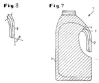
- the free 5 end of the handle 2 is preferably shaped to facilitate its insertion into, and passage through, the cut-out region 7 of the sleeve 6 in the process that will be described in more detail below. Accordingly, as shown in Figure 8, it is preferred that the angle ( ⁇ ) subtended in a vertical plane at the outer edge of the free end of the handle is a rather acute angle, preferably less than about 80°, more preferably less than 65°.
- the bottle 3 may be formed by any convenient means, blow-molding being the most commonly used.
- the bottle 3 has an internal volume of at least 1 litre and of less than 5 litres, and more preferably less than 3 litres.
- the bottle is shrink-sleeved.
- Shrink-sleeving consists in enveloping a part of the bottle in a tube-like flexible sleeve.
- the material of the sleeve is thermoplastic, and the sleeve is heated to shrink closely around the outer surface of the bottle.
- the sleeve may be made from a single film of plastic, or laminated in two or more layers.
- the plastic film may be either coloured or glass clear transparent glossy film which will be printed upon, or, alternatively, in the case of a laminated film, at least one layer of film may be pigmented by the addition of dyes or pigments before or at the point of extruding the laminate.
- the plastic film may also be decorated with colours, designs, logos, usage instructions, health and regulatory symbols and warnings, and other written or graphical information. This may be done by flexo- or gravure-printing.
- a preferred method, known as reverse printing, is to print the colours on the inside of the label in order to maintain its glossiness.
- the sleeve is formed by forming the plastic film essentially into a tube, preferably by folding the film back upon itself and forming a seam, and cutting the tube to form individual sleeves.
- a cut-out 7 is made in the sleeve 6.
- the cut-out 7 is surrounded on all of its sides by the plastic film material of the sleeve 6 which defines a hole in the sleeve.
- the profile of the cut-out region is at least as big as the cross-sectional profile of the free end 5 of the handle 2.
- the profile of the cut-out is generally round or oval-shaped, or it may be square or rectangular with rounded corners. Sharp corners are preferably avoided because these tend to distort or tear when the sleeve is shrunk.
- the cutting of the sleeve, and the forming of the cut-out 7 within the sleeve 6, can be achieved by various means such as mechanical die cutting, laser cutting or water jet cutting.
- the sleeve 6, in the form of an open tube, is disposed over and around the bottle 3 ( Figure 3).
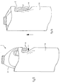
- the sleeve 6 is displaced relative to the bottle 6 so that the cut-out region 7 of the sleeve is adjacent to the free end 5 of the handle ( Figure 4). This allows the cut-out region 7 of the sleeve 6 to be positioned around the free end 5 of the handle 2.
- the sleeve 6 is then deformed ( Figure 5) adjacent to the cut-out region 7 so that the cut-out region 7 encompasses the free end 5 of the handle 2 and the sleeve 6 is subsequently displaced so that the sleeve 6 generally surrounds the bottle 3, and the handle 2 is disposed through, and protrudes out of, the cut-out region 7 of the sleeve 6 ( Figure 6).
- the result of this process is that the handle 2 is pushed through the cut-out 7 of the sleeve 6 until the sleeve 6 substantially surrounds the outer surface of the bottle and the handle 2 is disposed though the cut-out 7. The handle 2 is thus exposed outside of the sleeve 6.
- the sleeving process can be carried out on conventional bottle sleeving apparatus. It is necessary only to modify such apparatus by providing the means by which the sleeve 6 is deformed so that the cut-out region 7 of the sleeve 6 encompasses the free end 5 of the handle 2.
- a deforming means could, for example, be a cam in combination with a deforming bar.
- the bottle is held with its major axis in a vertical plane and either the bottle is maintained without vertical displacement while the sleeve is displaced vertically relative to the bottle; or the sleeve is maintained without vertical displacement while the bottle is displaced vertically relative to the sleeve.
- the sleeve and bottle are displaced relative to one another.
- the shrinking of the sleeve around the outer surface of the bottle is preferably carried out by passing the bottle and the sleeve through a shrink tunnel in which hot steam or hot air is blown onto the sleeve causing it to shrink and take the shape of the bottle.
- a shrink tunnel in which hot steam or hot air is blown onto the sleeve causing it to shrink and take the shape of the bottle.
- infrared radiation may be used.
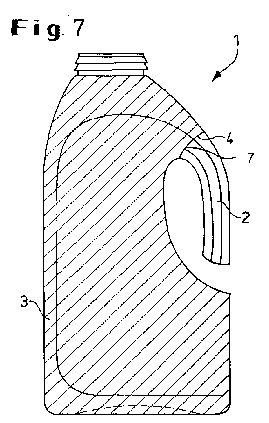
- the finished shrink-sleeved bottle is illustrated in Figure 7.
- the shrunk sleeve covers at least 30% of the outer surface of the bottle, and preferably covers at least 50% of the outer surface of the bottle, and more preferably covers at least 70% of the outer surface of the bottle.
- the cut-out region 7 of the sleeve 6 is juxtaposed with the merging region 4 between the handle 2 and the bottle 3 after the sleeve has been shrunk to the outer surface of the bottle, as illustrated in Figure 7. This maximises the surface of the bottle which is covered by the sleeve, and consequently provides the greatest surface area which can be decorated as described hereinabove.
Abstract
Description
- The present invention relates to a process for the manufacture of a decorated bottle, the bottle having a handle. In particular it relates to a bottle having a decorated sleeve shrunk around the outside of the bottle.
- Bottles are widely used in consumer goods industry for packaging various type of fluid products. Such bottles are normally decorated, often using labels which are stuck onto the bottle. Such labels are typically used not only for decoration but also to display usage instructions or information on the composition of the content for example. However, conventional labelling technology such as wet glue labels, self-adhesive labels, or in mold labels do not allow to decorate the full bottle surface area. The accumulation of such visual signals led the industry to develop new approaches allowing higher decoration coverage of the container's surface, one of these new approaches being the shrink-sleeving of packages.
- Shrink-sleeving is mostly used in the drinks industry, whereby a sleeve of thermo-plastic material may be shrunk all around a beverage bottle, thus offering an extended area which may be used for any type of graphics. Typical thermoplastic materials used for shrink sleeving include polyvinylchloride (PVC); low or high density polyethylene (LDPE, HDPE); polyester teraphthalate (PET); polypropylene (PP) and oriented polypropylene (OPP); polystyrene (PS) and oriented polystyrene (OPS); and mixtures thereof.
- However, use of shrink-sleeving did not extend to relatively larger containers, particularly because of the need of a side handle when such containers are used. Indeed, the sleeving of a bottle consists in inserting the bottle into a straight sleeve of thermoplastic material, the thermoplastic then being heated to shrink and fit tightly around the container. Clearly, in case of a container or bottle having a side handle, such a process would lead to preventing access to the handle as the sleeve would cover the recess produced by the handle, so that the handle cannot be gripped.
- EP-A-0 609 575, published on 10th August 1994, discloses a sleeved bottle having a handle which merges with the side of the bottle at two regions (i.e. top and bottom of the handle). The sleeve is provided with a cut-out substantially corresponding to the position of the gripping handle. However, when a shrink-sleeving process is used, it has been found to be difficult to assemble the sleeve and the bottle in such a way that the size and position of the cut-out is always accurate. The cut-out must be relatively large in order to extend between both of the two merged regions of the handle and bottle, so that the cut-out region encompasses the whole handle. The relatively large cut-out is prone to misalignment and or tearing during the sleeving process. Furthermore the process may leave sharp, exposed edges of the sleeve around the cut-out region which may cause discomfort to the user or, in extreme cases, may cut the finger of the user.
- The present invention addresses the problems by providing a bottle having a sleeve around the outside of the bottle, and having a handle, the handle being substantially exposed outside of the sleeve.
- The process of the present invention comprises the steps of:
- a) forming a bottle with a handle, the handle having opposing ends, wherein one end of the handle merges with the bottle in a merging region, and the other end of the handle is a free end;
- b) forming a sleeve essentially in the shape of a tube, the sleeve having at least one cut-out region which is defined on all sides by the sleeve, and wherein the profile of the cut-out region is at least as big as the cross-sectional profile of the free end of the handle;
- c) opening the generally tubular sleeve and disposing the open sleeve over the bottle;
- d) displacing the sleeve relative to the bottle so that the cut-out region of the sleeve is adjacent to the free end of the handle;
- e) deforming the sleeve so that the cut-out region encompasses the free end of the handle;
- f) displacing the sleeve relative to the bottle so that the sleeve generally surrounds the bottle, and so that the handle is disposed through the cut-out region of the sleeve; and
- g) shrinking the sleeve to the outer surface of the bottle.
-
-
- Figure 1 shows a bottle with a side handle suitable for use in the process of the present invention (step a).
- Figure 2 shows a sleeve with a cut-out region suitable for use in the process of the present invention (step b).
- Figure 3 shows the open sleeve of figure 2 placed over and around the bottle of Figure 1.
- Figure 4 shows the displacement of the sleeve relative to the bottle so that the cut-out region of the sleeve is adjacent to the free end of the handle (step d of the process of the present invention).
- Figure 5 shows the deformation of the sleeve so that the cut-out region encompasses the free end of the handle (step e of the process of the present invention).
- Figure 6 shows the displacement of the sleeve relative to the bottle so that the sleeve generally surrounds the bottle, and so that the handle is disposed through the cut-out region of the sleeve handle (step f of the process of the present invention).
- Figure 7 shows an example of a finished shrink-sleeved bottle made according to the process of the present invention.
- Figure 8 illustrates the angle (β) subtended in the vertical plane at the outer edge of the free end of the handle.
-
- The invention relates to a decorated bottle where the means of decoration is a shrink sleeve. The term bottle hereby should be understood generally as a container for fluid products, fluid products including liquids or gels as well as flowing materials such as powders or granules.
- The bottle has a base. By a base it should be understood a part of the bottle on which the bottle is left to stand up-right. This part my be flat, or may for example be formed from a moulded tripod, or from a flat ring. Many types of "base" are known in the art, the main feature of such a base being to hold the bottle in a stable position on a flat supporting surface. The bottle also has a major axis which is generally perpendicular to the plane of the base.
- The bottle further comprises a top part. The top part is typically the part of the bottle opposed to the base. The top is commonly the part of the bottle which is provided with an aperture for emptying and optionally refilling the bottle. The aperture is generally provided with a closure.
- The bottle also comprises sides. The sides are the surfaces which, in general terms, join the top and the base of the bottle. Typically, when the bottle is upright, the sides are substantially vertical and perpendicular to the base. The sides may also have a curved or relatively complex shape depending on the bottle considered.
- A typical bottle for use in the present invention is illustrated in Figure 1. The
bottle 3 according to the present invention further comprises ahandle 2 disposed on a side of the bottle. This makes the bottle different from bottles without handles (such as, for example, typical bottles for soda or beer), and also from bottle with a handle on the top part (such as "heavy" bottles of the type used for containing more than 5 liters of petrol for example). Thehandle 2 is joined to the side of thebottle 3 at a merging region 4. Thehandle 2 according to the invention is, for example, forming a recess in the generally vertical direction when thebottle 3 is standing upright upon its base, the recess being such that a user may slide the hand in the recess to hold, lift and pour from the bottle. - The free 5 end of the
handle 2 is preferably shaped to facilitate its insertion into, and passage through, the cut-outregion 7 of the sleeve 6 in the process that will be described in more detail below. Accordingly, as shown in Figure 8, it is preferred that the angle (β) subtended in a vertical plane at the outer edge of the free end of the handle is a rather acute angle, preferably less than about 80°, more preferably less than 65°. - The
bottle 3 may be formed by any convenient means, blow-molding being the most commonly used. Preferably thebottle 3 has an internal volume of at least 1 litre and of less than 5 litres, and more preferably less than 3 litres. - Further, the bottle is shrink-sleeved. Shrink-sleeving consists in enveloping a part of the bottle in a tube-like flexible sleeve. Preferably the material of the sleeve is thermoplastic, and the sleeve is heated to shrink closely around the outer surface of the bottle. The sleeve may be made from a single film of plastic, or laminated in two or more layers. The plastic film may be either coloured or glass clear transparent glossy film which will be printed upon, or, alternatively, in the case of a laminated film, at least one layer of film may be pigmented by the addition of dyes or pigments before or at the point of extruding the laminate. The plastic film may also be decorated with colours, designs, logos, usage instructions, health and regulatory symbols and warnings, and other written or graphical information. This may be done by flexo- or gravure-printing. A preferred method, known as reverse printing, is to print the colours on the inside of the label in order to maintain its glossiness. The sleeve is formed by forming the plastic film essentially into a tube, preferably by folding the film back upon itself and forming a seam, and cutting the tube to form individual sleeves.
- According to the present invention, illustrated in Figure 2, a cut-
out 7 is made in the sleeve 6. The cut-out 7 is surrounded on all of its sides by the plastic film material of the sleeve 6 which defines a hole in the sleeve. The profile of the cut-out region is at least as big as the cross-sectional profile of thefree end 5 of thehandle 2. Preferably the profile of the cut-out is generally round or oval-shaped, or it may be square or rectangular with rounded corners. Sharp corners are preferably avoided because these tend to distort or tear when the sleeve is shrunk. - The cutting of the sleeve, and the forming of the cut-out 7 within the sleeve 6, can be achieved by various means such as mechanical die cutting, laser cutting or water jet cutting.
- According to the present invention the sleeve 6, in the form of an open tube, is disposed over and around the bottle 3 (Figure 3). The sleeve 6 is displaced relative to the bottle 6 so that the cut-out
region 7 of the sleeve is adjacent to thefree end 5 of the handle (Figure 4). This allows the cut-outregion 7 of the sleeve 6 to be positioned around thefree end 5 of thehandle 2. The sleeve 6 is then deformed (Figure 5) adjacent to the cut-outregion 7 so that the cut-outregion 7 encompasses thefree end 5 of thehandle 2 and the sleeve 6 is subsequently displaced so that the sleeve 6 generally surrounds thebottle 3, and thehandle 2 is disposed through, and protrudes out of, the cut-outregion 7 of the sleeve 6 (Figure 6). The result of this process is that thehandle 2 is pushed through the cut-out 7 of the sleeve 6 until the sleeve 6 substantially surrounds the outer surface of the bottle and thehandle 2 is disposed though the cut-out 7. Thehandle 2 is thus exposed outside of the sleeve 6. - The sleeving process can be carried out on conventional bottle sleeving apparatus. It is necessary only to modify such apparatus by providing the means by which the sleeve 6 is deformed so that the cut-out
region 7 of the sleeve 6 encompasses thefree end 5 of thehandle 2. Such a deforming means could, for example, be a cam in combination with a deforming bar. - In alternative embodiments of the invention the bottle is held with its major axis in a vertical plane and either the bottle is maintained without vertical displacement while the sleeve is displaced vertically relative to the bottle; or the sleeve is maintained without vertical displacement while the bottle is displaced vertically relative to the sleeve. Of course a combination of both embodiments is possible provided the sleeve and bottle are displaced relative to one another.
- The shrinking of the sleeve around the outer surface of the bottle is preferably carried out by passing the bottle and the sleeve through a shrink tunnel in which hot steam or hot air is blown onto the sleeve causing it to shrink and take the shape of the bottle. Alternatively infrared radiation may be used. The finished shrink-sleeved bottle is illustrated in Figure 7.
- Preferably the shrunk sleeve covers at least 30% of the outer surface of the bottle, and preferably covers at least 50% of the outer surface of the bottle, and more preferably covers at least 70% of the outer surface of the bottle.
- In a particularly preferred embodiment of the present invention the cut-out
region 7 of the sleeve 6 is juxtaposed with the merging region 4 between thehandle 2 and thebottle 3 after the sleeve has been shrunk to the outer surface of the bottle, as illustrated in Figure 7. This maximises the surface of the bottle which is covered by the sleeve, and consequently provides the greatest surface area which can be decorated as described hereinabove.
Claims (7)
- A process for the manufacture of a bottle, the bottle (3) having a sleeve (6) around the outside of the bottle (3), and having a handle (2), the handle (2) being substantially exposed outside of the sleeve (6), wherein the process comprises the steps of:a) forming a bottle (3) with a handle (2), the handle (2) having opposing ends, wherein one end of the handle merges with the bottle in a merging region (4), and the other end of the handle is a free end (5);b) forming a flexible sleeve (6) essentially in the shape of a tube, the sleeve (6) having at least one cut-out region (7) which is defined on all sides by the sleeve (6), and wherein the profile of the cut-out region (7) is at least as big as the cross-sectional profile of the free end of the handle (5);c) opening the generally tubular sleeve (6) and disposing the open sleeve over the bottle (3);d) displacing the sleeve (6) relative to the bottle (3) so that the cut-out region (7) of the sleeve is adjacent to the free end of the handle (5);e) deforming the sleeve (6) so that the cut-out region (7) encompasses the free end of the handle (5);f) displacing the sleeve (6) relative to the bottle (3) so that the sleeve (6) generally surrounds the bottle (3), and so that the handle (2) is disposed through the cut-out region (7) of the sleeve; andg) shrinking the sleeve (6) to the outer surface of the bottle (3).
- A process according to claim 1 wherein the sleeve (6) comprises a thermoplastic material and wherein the shrinking step g) comprises the application of heat.
- A process according to either of claims 1 or 2 wherein the cut-out region (7) of the sleeve is juxtaposed with the merging region (4) between the handle (2) and the bottle after the sleeve (6) has been shrunk to the outer surface of the bottle (3).
- A process according to any of claims 1 to 3 wherein in steps d) and f) the bottle is held with its major axis in a vertical plane and the bottle (3) is maintained without vertical displacement while the sleeve (6) is displaced vertically relative to the bottle (3).
- A process according to any of claims 1 to 3 wherein in steps d) and f) the bottle is held with its major axis in a vertical plane and the sleeve (6) is maintained without vertical displacement while the bottle (3) is displaced vertically relative to the sleeve (6).
- The process according to any of the previous claims, whereby the shrunk sleeve covers at least 30% of the outer surface of the bottle (3), and preferably covers at least 50% of the outer surface of the bottle (3), and more preferably covers at least 70% of the outer surface of the bottle (3).
- The process according to any of the previous claims, whereby the bottle (3) has an internal volume of at least 1 litre and of less than 5 litres.
Priority Applications (12)
| Application Number | Priority Date | Filing Date | Title |
|---|---|---|---|
| ES01200914T ES2217086T3 (en) | 2001-03-08 | 2001-03-08 | PROCEDURE TO COAT A BOTTLE WITH HANDLE WITH A SHRINKED HOSE. |
| EP01200914A EP1238916B1 (en) | 2001-03-08 | 2001-03-08 | Process for shirnk sleeveing bottle with a handle |
| DE60103244T DE60103244T2 (en) | 2001-03-08 | 2001-03-08 | Method for wrapping a bottle by means of a Schrupfschlauchs |
| AT01200914T ATE266577T1 (en) | 2001-03-08 | 2001-03-08 | METHOD OF COVERING A BOTTLE USING A SHRINK TUBING |
| CNB028061896A CN100347048C (en) | 2001-03-08 | 2002-03-06 | Process for making shrink sleeved bottle with handle |
| CA002435948A CA2435948A1 (en) | 2001-03-08 | 2002-03-06 | Process for shrink sleeved a bottle with a handle |
| BR0207908-9A BR0207908A (en) | 2001-03-08 | 2002-03-06 | Process for manufacturing a retractable sleeve bottle with handle |
| EP02721285A EP1417133A1 (en) | 2001-03-08 | 2002-03-06 | Process for shrink sleeving a bottle with a handle |
| JP2002571371A JP3917077B2 (en) | 2001-03-08 | 2002-03-06 | Method for manufacturing bottle with shrink sleeve having handle |
| MXPA03008112A MXPA03008112A (en) | 2001-03-08 | 2002-03-06 | Process for shrink sleeved a bottle with a handle. |
| PCT/US2002/006928 WO2002072441A1 (en) | 2001-03-08 | 2002-03-06 | Process for shrink sleeved a bottle with a handle |
| US10/093,043 US6730253B2 (en) | 2001-03-08 | 2002-03-07 | Process for the manufacture of a shrink sleeved bottle with a handle |
Applications Claiming Priority (1)
| Application Number | Priority Date | Filing Date | Title |
|---|---|---|---|
| EP01200914A EP1238916B1 (en) | 2001-03-08 | 2001-03-08 | Process for shirnk sleeveing bottle with a handle |
Publications (2)
| Publication Number | Publication Date |
|---|---|
| EP1238916A1 true EP1238916A1 (en) | 2002-09-11 |
| EP1238916B1 EP1238916B1 (en) | 2004-05-12 |
Family
ID=8180000
Family Applications (2)
| Application Number | Title | Priority Date | Filing Date |
|---|---|---|---|
| EP01200914A Expired - Lifetime EP1238916B1 (en) | 2001-03-08 | 2001-03-08 | Process for shirnk sleeveing bottle with a handle |
| EP02721285A Withdrawn EP1417133A1 (en) | 2001-03-08 | 2002-03-06 | Process for shrink sleeving a bottle with a handle |
Family Applications After (1)
| Application Number | Title | Priority Date | Filing Date |
|---|---|---|---|
| EP02721285A Withdrawn EP1417133A1 (en) | 2001-03-08 | 2002-03-06 | Process for shrink sleeving a bottle with a handle |
Country Status (11)
| Country | Link |
|---|---|
| US (1) | US6730253B2 (en) |
| EP (2) | EP1238916B1 (en) |
| JP (1) | JP3917077B2 (en) |
| CN (1) | CN100347048C (en) |
| AT (1) | ATE266577T1 (en) |
| BR (1) | BR0207908A (en) |
| CA (1) | CA2435948A1 (en) |
| DE (1) | DE60103244T2 (en) |
| ES (1) | ES2217086T3 (en) |
| MX (1) | MXPA03008112A (en) |
| WO (1) | WO2002072441A1 (en) |
Cited By (4)
| Publication number | Priority date | Publication date | Assignee | Title |
|---|---|---|---|---|
| EP1457427A1 (en) * | 2003-03-12 | 2004-09-15 | The Procter & Gamble Company | Apparatus for the manufacture of a sleeved bottle |
| WO2013104433A1 (en) * | 2012-01-09 | 2013-07-18 | Henkel Ag & Co. Kgaa | Bottle having a shrink-fitted plastic film and method for producing same |
| US9637264B2 (en) | 2010-01-28 | 2017-05-02 | Avery Dennison Corporation | Label applicator belt system |
| WO2023018750A1 (en) * | 2021-08-10 | 2023-02-16 | The Procter & Gamble Company | Container systems that include sleeve labels |
Families Citing this family (17)
| Publication number | Priority date | Publication date | Assignee | Title |
|---|---|---|---|---|
| DE69905159T2 (en) | 1999-09-10 | 2003-10-09 | Procter & Gamble | Bottle with a shrunk sleeve |
| US20050139568A1 (en) * | 2003-12-31 | 2005-06-30 | Unilever Home & Personal Care Usa | Shrink sleeved bottle |
| CA2568588C (en) * | 2004-06-14 | 2010-12-21 | The Procter & Gamble Company | Package for personal care products comprising a shrink label |
| US20060141182A1 (en) * | 2004-12-29 | 2006-06-29 | Unilever Home & Personal Care Usa, Division Of Conopco, Inc. | Shrink label container with post applied handle |
| US20070048473A1 (en) * | 2005-08-29 | 2007-03-01 | The Procter & Gamble Company | Injection stretch blow-molded container |
| US7665638B2 (en) * | 2005-10-28 | 2010-02-23 | The Sun Products Corporation | Packaged liquid laundry compositions |
| ES2364074T3 (en) * | 2005-11-03 | 2011-08-24 | Strategic Solutions International, Llc | ISOLATED BOTTLE CONTAINER. |
| CN106564668A (en) | 2007-04-05 | 2017-04-19 | 艾利丹尼森公司 | Pressure sensitive shrink label |
| US8282754B2 (en) | 2007-04-05 | 2012-10-09 | Avery Dennison Corporation | Pressure sensitive shrink label |
| US7963425B2 (en) * | 2007-12-13 | 2011-06-21 | The Clorox Company | Shrink sleeve for pump dispenser |
| IT1399272B1 (en) * | 2010-04-06 | 2013-04-11 | Soremartec Sa | "PROCEDURE FOR REALIZING CONTAINERS AND ITS CONTAINER" |
| JP6078240B2 (en) * | 2012-06-28 | 2017-02-08 | 株式会社吉野工業所 | Manufacturing method of bottle with handle |
| USD717666S1 (en) | 2014-03-14 | 2014-11-18 | The Clorox Company | Fluid dispenser |
| ES2786093T3 (en) * | 2015-11-13 | 2020-10-08 | Mondi Ag | Film bag |
| EP3873816A1 (en) * | 2018-10-31 | 2021-09-08 | The Procter & Gamble Company | Container with apertured shrink sleeve and related processes |
| US20220332466A1 (en) * | 2019-09-27 | 2022-10-20 | Fuji Seal International, Inc. | Shrink label and method of use |
| DE102021122353A1 (en) | 2021-08-30 | 2023-03-02 | Henkel Ag & Co. Kgaa | Packaging with a PET bottle and at least two sleeves made from a shrink film |
Citations (2)
| Publication number | Priority date | Publication date | Assignee | Title |
|---|---|---|---|---|
| US4368827A (en) * | 1979-05-21 | 1983-01-18 | Thompson Mortimer S | Container with integral handle and method of forming same |
| EP0609575A1 (en) | 1993-02-02 | 1994-08-10 | The Procter & Gamble Company | Composite package |
Family Cites Families (15)
| Publication number | Priority date | Publication date | Assignee | Title |
|---|---|---|---|---|
| US4051265A (en) | 1974-10-10 | 1977-09-27 | Celanese Corporation | Package for light and oxygen sensitive food |
| JPS5256695A (en) | 1975-12-06 | 1977-05-10 | Sony Corp | Packing device |
| US4257525A (en) | 1979-04-10 | 1981-03-24 | Thompson Mortimer S | Bottle with attached handle |
| US4629598A (en) * | 1979-04-10 | 1986-12-16 | Tri-Tech Systems International, Inc. | Method for forming plastic bottle with integral handle |
| US5086937A (en) | 1990-10-09 | 1992-02-11 | Owens-Illinois Plastic Products Inc. | Lightweight plastic bottle and method and apparatus for forming |
| GB2251844B (en) * | 1990-12-29 | 1995-07-05 | A K Tech Lab Inc | Bottle with handle |
| CN1023099C (en) * | 1990-12-29 | 1993-12-15 | 株式会社青木固研究所 | Bottle with handle |
| US5122399A (en) | 1991-10-15 | 1992-06-16 | Westvaco Corporation | Paperboard bottle |
| US5383558A (en) | 1992-09-11 | 1995-01-24 | Kraft General Foods, Inc. | Sealed container |
| US5524787A (en) | 1993-02-02 | 1996-06-11 | The Procter & Gamble Company | Lightweight, composite container |
| CN2214365Y (en) * | 1994-10-27 | 1995-12-06 | 远纺实业股份有限公司 | Close-by-insertion handle for plastic vessel |
| US5676314A (en) | 1995-04-04 | 1997-10-14 | H.D. Hudson Manufacturing Company | Limited time use sprayer |
| US5836469A (en) | 1996-01-24 | 1998-11-17 | Zebrowski; Stanton | Bottle with gripping support |
| ES2177213T3 (en) | 1999-09-10 | 2002-12-01 | Procter & Gamble | BOTTLE COVERED BY A Shrinkable Sleeve. |
| DE69905159T2 (en) | 1999-09-10 | 2003-10-09 | Procter & Gamble | Bottle with a shrunk sleeve |
-
2001
- 2001-03-08 EP EP01200914A patent/EP1238916B1/en not_active Expired - Lifetime
- 2001-03-08 DE DE60103244T patent/DE60103244T2/en not_active Expired - Lifetime
- 2001-03-08 ES ES01200914T patent/ES2217086T3/en not_active Expired - Lifetime
- 2001-03-08 AT AT01200914T patent/ATE266577T1/en not_active IP Right Cessation
-
2002
- 2002-03-06 CN CNB028061896A patent/CN100347048C/en not_active Expired - Fee Related
- 2002-03-06 EP EP02721285A patent/EP1417133A1/en not_active Withdrawn
- 2002-03-06 BR BR0207908-9A patent/BR0207908A/en not_active Application Discontinuation
- 2002-03-06 MX MXPA03008112A patent/MXPA03008112A/en unknown
- 2002-03-06 JP JP2002571371A patent/JP3917077B2/en not_active Expired - Fee Related
- 2002-03-06 WO PCT/US2002/006928 patent/WO2002072441A1/en not_active Application Discontinuation
- 2002-03-06 CA CA002435948A patent/CA2435948A1/en not_active Abandoned
- 2002-03-07 US US10/093,043 patent/US6730253B2/en not_active Expired - Fee Related
Patent Citations (2)
| Publication number | Priority date | Publication date | Assignee | Title |
|---|---|---|---|---|
| US4368827A (en) * | 1979-05-21 | 1983-01-18 | Thompson Mortimer S | Container with integral handle and method of forming same |
| EP0609575A1 (en) | 1993-02-02 | 1994-08-10 | The Procter & Gamble Company | Composite package |
Cited By (4)
| Publication number | Priority date | Publication date | Assignee | Title |
|---|---|---|---|---|
| EP1457427A1 (en) * | 2003-03-12 | 2004-09-15 | The Procter & Gamble Company | Apparatus for the manufacture of a sleeved bottle |
| US9637264B2 (en) | 2010-01-28 | 2017-05-02 | Avery Dennison Corporation | Label applicator belt system |
| WO2013104433A1 (en) * | 2012-01-09 | 2013-07-18 | Henkel Ag & Co. Kgaa | Bottle having a shrink-fitted plastic film and method for producing same |
| WO2023018750A1 (en) * | 2021-08-10 | 2023-02-16 | The Procter & Gamble Company | Container systems that include sleeve labels |
Also Published As
| Publication number | Publication date |
|---|---|
| ATE266577T1 (en) | 2004-05-15 |
| DE60103244D1 (en) | 2004-06-17 |
| EP1238916B1 (en) | 2004-05-12 |
| EP1417133A1 (en) | 2004-05-12 |
| US6730253B2 (en) | 2004-05-04 |
| BR0207908A (en) | 2004-07-27 |
| MXPA03008112A (en) | 2003-12-12 |
| DE60103244T2 (en) | 2005-05-04 |
| CA2435948A1 (en) | 2002-09-19 |
| JP2004522658A (en) | 2004-07-29 |
| CN100347048C (en) | 2007-11-07 |
| ES2217086T3 (en) | 2004-11-01 |
| US20020124931A1 (en) | 2002-09-12 |
| WO2002072441A1 (en) | 2002-09-19 |
| CN1496324A (en) | 2004-05-12 |
| JP3917077B2 (en) | 2007-05-23 |
Similar Documents
| Publication | Publication Date | Title |
|---|---|---|
| EP1238916B1 (en) | Process for shirnk sleeveing bottle with a handle | |
| EP1083129B1 (en) | Shrink sleeved bottle | |
| CN104136340B (en) | There is the liquid bottle of the cover part forming extendible portion with label | |
| EP1083041B1 (en) | Shrink sleeved bottle | |
| US20030192787A1 (en) | Multiple pack bottle holder | |
| CN103764508B (en) | There is the liquid bottle of the cover part being made up of its extendible portion label | |
| EP0609575A1 (en) | Composite package | |
| EP3419907B1 (en) | Container with removable insert | |
| JP6109407B2 (en) | Liquid-filled bottle having a thin cover member with a flexible reinforcing element | |
| US20060141182A1 (en) | Shrink label container with post applied handle | |
| CA3052500C (en) | Alignment of a window on a container | |
| US20040013326A1 (en) | Squeezable two-piece stand-up tube | |
| RU33931U1 (en) | Bottle set with uncoupling device | |
| JP2001122272A (en) | Thin wall bottle container with label |
Legal Events
| Date | Code | Title | Description |
|---|---|---|---|
| PUAI | Public reference made under article 153(3) epc to a published international application that has entered the european phase |
Free format text: ORIGINAL CODE: 0009012 |
|
| AK | Designated contracting states |
Kind code of ref document: A1 Designated state(s): AT BE CH CY DE DK ES FI FR GB GR IE IT LI LU MC NL PT SE TR |
|
| AX | Request for extension of the european patent |
Free format text: AL;LT;LV;MK;RO;SI |
|
| 17P | Request for examination filed |
Effective date: 20030110 |
|
| AKX | Designation fees paid |
Designated state(s): AT BE CH CY DE DK ES FI FR GB GR IE IT LI LU MC NL PT SE TR |
|
| GRAP | Despatch of communication of intention to grant a patent |
Free format text: ORIGINAL CODE: EPIDOSNIGR1 |
|
| GRAS | Grant fee paid |
Free format text: ORIGINAL CODE: EPIDOSNIGR3 |
|
| GRAA | (expected) grant |
Free format text: ORIGINAL CODE: 0009210 |
|
| AK | Designated contracting states |
Kind code of ref document: B1 Designated state(s): AT BE CH CY DE DK ES FI FR GB GR IE IT LI LU MC NL PT SE TR |
|
| PG25 | Lapsed in a contracting state [announced via postgrant information from national office to epo] |
Ref country code: LI Free format text: LAPSE BECAUSE OF FAILURE TO SUBMIT A TRANSLATION OF THE DESCRIPTION OR TO PAY THE FEE WITHIN THE PRESCRIBED TIME-LIMIT Effective date: 20040512 Ref country code: AT Free format text: LAPSE BECAUSE OF FAILURE TO SUBMIT A TRANSLATION OF THE DESCRIPTION OR TO PAY THE FEE WITHIN THE PRESCRIBED TIME-LIMIT Effective date: 20040512 Ref country code: TR Free format text: LAPSE BECAUSE OF FAILURE TO SUBMIT A TRANSLATION OF THE DESCRIPTION OR TO PAY THE FEE WITHIN THE PRESCRIBED TIME-LIMIT Effective date: 20040512 Ref country code: CH Free format text: LAPSE BECAUSE OF FAILURE TO SUBMIT A TRANSLATION OF THE DESCRIPTION OR TO PAY THE FEE WITHIN THE PRESCRIBED TIME-LIMIT Effective date: 20040512 Ref country code: FI Free format text: LAPSE BECAUSE OF FAILURE TO SUBMIT A TRANSLATION OF THE DESCRIPTION OR TO PAY THE FEE WITHIN THE PRESCRIBED TIME-LIMIT Effective date: 20040512 |
|
| REG | Reference to a national code |
Ref country code: GB Ref legal event code: FG4D |
|
| REG | Reference to a national code |
Ref country code: CH Ref legal event code: EP |
|
| REG | Reference to a national code |
Ref country code: IE Ref legal event code: FG4D |
|
| REF | Corresponds to: |
Ref document number: 60103244 Country of ref document: DE Date of ref document: 20040617 Kind code of ref document: P |
|
| PG25 | Lapsed in a contracting state [announced via postgrant information from national office to epo] |
Ref country code: DK Free format text: LAPSE BECAUSE OF FAILURE TO SUBMIT A TRANSLATION OF THE DESCRIPTION OR TO PAY THE FEE WITHIN THE PRESCRIBED TIME-LIMIT Effective date: 20040812 Ref country code: GR Free format text: LAPSE BECAUSE OF FAILURE TO SUBMIT A TRANSLATION OF THE DESCRIPTION OR TO PAY THE FEE WITHIN THE PRESCRIBED TIME-LIMIT Effective date: 20040812 Ref country code: SE Free format text: LAPSE BECAUSE OF FAILURE TO SUBMIT A TRANSLATION OF THE DESCRIPTION OR TO PAY THE FEE WITHIN THE PRESCRIBED TIME-LIMIT Effective date: 20040812 |
|
| REG | Reference to a national code |
Ref country code: ES Ref legal event code: FG2A Ref document number: 2217086 Country of ref document: ES Kind code of ref document: T3 |
|
| REG | Reference to a national code |
Ref country code: CH Ref legal event code: PL |
|
| ET | Fr: translation filed | ||
| PG25 | Lapsed in a contracting state [announced via postgrant information from national office to epo] |
Ref country code: LU Free format text: LAPSE BECAUSE OF NON-PAYMENT OF DUE FEES Effective date: 20050308 Ref country code: IE Free format text: LAPSE BECAUSE OF NON-PAYMENT OF DUE FEES Effective date: 20050308 Ref country code: CY Free format text: LAPSE BECAUSE OF FAILURE TO SUBMIT A TRANSLATION OF THE DESCRIPTION OR TO PAY THE FEE WITHIN THE PRESCRIBED TIME-LIMIT Effective date: 20050308 |
|
| PLBE | No opposition filed within time limit |
Free format text: ORIGINAL CODE: 0009261 |
|
| STAA | Information on the status of an ep patent application or granted ep patent |
Free format text: STATUS: NO OPPOSITION FILED WITHIN TIME LIMIT |
|
| PG25 | Lapsed in a contracting state [announced via postgrant information from national office to epo] |
Ref country code: MC Free format text: LAPSE BECAUSE OF NON-PAYMENT OF DUE FEES Effective date: 20050331 |
|
| 26N | No opposition filed |
Effective date: 20050215 |
|
| REG | Reference to a national code |
Ref country code: IE Ref legal event code: MM4A |
|
| PG25 | Lapsed in a contracting state [announced via postgrant information from national office to epo] |
Ref country code: PT Free format text: LAPSE BECAUSE OF NON-PAYMENT OF DUE FEES Effective date: 20041012 |
|
| PGFP | Annual fee paid to national office [announced via postgrant information from national office to epo] |
Ref country code: ES Payment date: 20100323 Year of fee payment: 10 |
|
| PGFP | Annual fee paid to national office [announced via postgrant information from national office to epo] |
Ref country code: FR Payment date: 20100318 Year of fee payment: 10 Ref country code: IT Payment date: 20100324 Year of fee payment: 10 |
|
| PGFP | Annual fee paid to national office [announced via postgrant information from national office to epo] |
Ref country code: GB Payment date: 20100208 Year of fee payment: 10 |
|
| PGFP | Annual fee paid to national office [announced via postgrant information from national office to epo] |
Ref country code: NL Payment date: 20100402 Year of fee payment: 10 Ref country code: DE Payment date: 20100331 Year of fee payment: 10 |
|
| PGFP | Annual fee paid to national office [announced via postgrant information from national office to epo] |
Ref country code: BE Payment date: 20100504 Year of fee payment: 10 |
|
| BERE | Be: lapsed |
Owner name: THE *PROCTER & GAMBLE CY Effective date: 20110331 |
|
| REG | Reference to a national code |
Ref country code: NL Ref legal event code: V1 Effective date: 20111001 |
|
| GBPC | Gb: european patent ceased through non-payment of renewal fee |
Effective date: 20110308 |
|
| REG | Reference to a national code |
Ref country code: FR Ref legal event code: ST Effective date: 20111130 |
|
| PG25 | Lapsed in a contracting state [announced via postgrant information from national office to epo] |
Ref country code: BE Free format text: LAPSE BECAUSE OF NON-PAYMENT OF DUE FEES Effective date: 20110331 |
|
| PG25 | Lapsed in a contracting state [announced via postgrant information from national office to epo] |
Ref country code: NL Free format text: LAPSE BECAUSE OF NON-PAYMENT OF DUE FEES Effective date: 20111001 Ref country code: DE Free format text: LAPSE BECAUSE OF NON-PAYMENT OF DUE FEES Effective date: 20111001 Ref country code: FR Free format text: LAPSE BECAUSE OF NON-PAYMENT OF DUE FEES Effective date: 20110331 |
|
| REG | Reference to a national code |
Ref country code: DE Ref legal event code: R119 Ref document number: 60103244 Country of ref document: DE Effective date: 20111001 |
|
| PG25 | Lapsed in a contracting state [announced via postgrant information from national office to epo] |
Ref country code: GB Free format text: LAPSE BECAUSE OF NON-PAYMENT OF DUE FEES Effective date: 20110308 Ref country code: IT Free format text: LAPSE BECAUSE OF NON-PAYMENT OF DUE FEES Effective date: 20110308 |
|
| REG | Reference to a national code |
Ref country code: ES Ref legal event code: FD2A Effective date: 20120424 |
|
| PG25 | Lapsed in a contracting state [announced via postgrant information from national office to epo] |
Ref country code: ES Free format text: LAPSE BECAUSE OF NON-PAYMENT OF DUE FEES Effective date: 20110309 |