EP1239909B1 - Endotracheal catheter and manifold assembly with seal and valve - Google Patents
Endotracheal catheter and manifold assembly with seal and valve Download PDFInfo
- Publication number
- EP1239909B1 EP1239909B1 EP00986621A EP00986621A EP1239909B1 EP 1239909 B1 EP1239909 B1 EP 1239909B1 EP 00986621 A EP00986621 A EP 00986621A EP 00986621 A EP00986621 A EP 00986621A EP 1239909 B1 EP1239909 B1 EP 1239909B1
- Authority
- EP
- European Patent Office
- Prior art keywords
- catheter
- manifold
- seal
- valve
- port
- Prior art date
- Legal status (The legal status is an assumption and is not a legal conclusion. Google has not performed a legal analysis and makes no representation as to the accuracy of the status listed.)
- Expired - Lifetime
Links
Images


Classifications
-
- A—HUMAN NECESSITIES
- A61—MEDICAL OR VETERINARY SCIENCE; HYGIENE
- A61M—DEVICES FOR INTRODUCING MEDIA INTO, OR ONTO, THE BODY; DEVICES FOR TRANSDUCING BODY MEDIA OR FOR TAKING MEDIA FROM THE BODY; DEVICES FOR PRODUCING OR ENDING SLEEP OR STUPOR
- A61M16/00—Devices for influencing the respiratory system of patients by gas treatment, e.g. mouth-to-mouth respiration; Tracheal tubes
- A61M16/04—Tracheal tubes
- A61M16/0463—Tracheal tubes combined with suction tubes, catheters or the like; Outside connections
-
- A—HUMAN NECESSITIES
- A61—MEDICAL OR VETERINARY SCIENCE; HYGIENE
- A61M—DEVICES FOR INTRODUCING MEDIA INTO, OR ONTO, THE BODY; DEVICES FOR TRANSDUCING BODY MEDIA OR FOR TAKING MEDIA FROM THE BODY; DEVICES FOR PRODUCING OR ENDING SLEEP OR STUPOR
- A61M16/00—Devices for influencing the respiratory system of patients by gas treatment, e.g. mouth-to-mouth respiration; Tracheal tubes
- A61M16/08—Bellows; Connecting tubes ; Water traps; Patient circuits
- A61M16/0816—Joints or connectors
- A61M16/0825—Joints or connectors with ball-sockets
-
- A—HUMAN NECESSITIES
- A61—MEDICAL OR VETERINARY SCIENCE; HYGIENE
- A61M—DEVICES FOR INTRODUCING MEDIA INTO, OR ONTO, THE BODY; DEVICES FOR TRANSDUCING BODY MEDIA OR FOR TAKING MEDIA FROM THE BODY; DEVICES FOR PRODUCING OR ENDING SLEEP OR STUPOR
- A61M16/00—Devices for influencing the respiratory system of patients by gas treatment, e.g. mouth-to-mouth respiration; Tracheal tubes
- A61M16/10—Preparation of respiratory gases or vapours
- A61M16/105—Filters
- A61M16/106—Filters in a path
Definitions
- the present invention relates to a respiratory suction catheter assembly with an improved mechanism for cleaning the tip of the catheter without drawing an excessive amount of air from the respiration circuit to which the endotracheal catheter is attached. More specifically, the present invention relates principally to a closed suction endotracheal catheter system that provides improved cleaning of the catheter by incorporating a wiper seal and valve arrangement that isolates the distal end of the catheter during cleaning while minimizing or eliminating air drawn from the patient's ventilation circuit.
- an artificial airway such as an endotracheal tube
- the artificial airway's function is primarily to keep the patient's airway open so that adequate lung ventilation can be maintained during the procedure.
- the endotracheal tube will be left in the patient for a prolonged period of time. For example, with many patients, the endotracheal tube will remain in place to sustain mechanical ventilation for the life of the patient.
- an endotracheal tube is to be left in place for any substantial amount of time, it is critical that respiratory secretions be periodically removed. This is most often accomplished with the use of a respiratory suction catheter that is advanced into the endotracheal tube. As the suction catheter is withdrawn, a negative pressure is applied to the interior of the catheter to draw mucus and other secretions from the patient's respiratory system. While a substantial amount of the mucus and other secretions will be withdrawn through the catheter, a portion of the mucus and other secretions remain on the outside of the catheter.
- a patient's secretions can contain infectious agents, such as streptococcus, pseudomonus, staphylococcus, and even HIV, it is important to shield clinicians from contact with the catheter. Likewise, it is important to shield patients from communicable pathogens in the environment and those that may be carried by the clinician. This is particularly important because patients on mechanical ventilation often have compromised immune systems.
- suctioning a patient's artificial airway potentially interferes with proper respiration.
- the most common group of patients who have indwelling endotracheal tubes for prolonged periods are those who must be mechanically ventilated.
- Mechanically ventilated patients will typically have a fitting or manifold attached to the proximal end of the endotracheal tube (i.e., the end extending outside the patient) at an endotracheal tube hub.
- a pair of ventilator tubes extends from a mechanical ventilator and is typically attached to the manifold by an adapter.
- One tube provides inspiratory air to the patient for inhalation.
- the other tube allows for exhaled or expiratory air to exit the system.
- closed suction catheters In the last fifteen years, there has been a significant shift toward the use of closed suction catheter systems.
- the advantage of closed suction catheters is that the ventilating circuit is not detached from the patient during suction procedures, as it is during open suction procedures. Because the catheter is reused a number of times over a twenty-four hour period, it is important that mucus and other secretions are cleaned from the catheter prior to periods of non-use. If the secretions are not removed the risk of auto-contamination increases. It is also important to clean the catheter to maintain suction efficiency.
- U.S. Patent No. 4,569,344 discloses a lavage port which enables the user to inject liquid into the area surrounding the distal end of the catheter after it has been withdrawn from the patient.
- the liquid aids in loosening and removing the secretions from the exterior of the catheter.
- the suction also causes an undesired amount of respiratory air to be removed through the catheter.
- the air that is evacuated potentially disrupts the carefully controlled ventilatory cycles.
- the amount of respiratory air available to the patient is potentially decreased as a result of catheter cleaning. If the clinician has a difficult time cleaning secretions from the catheter, suction may be applied through the catheter several times - thereby repeatedly drawing air from the ventilatory circuit.
- U.S. Patent No. 5,487,381 discloses a closed suction catheter which has a lavage chamber configured to receive the distal tip of the catheter as it is withdrawn from the manifold. A wall is then slid from an open position to a closed position to isolate the distal end of the catheter from the manifold and the ventilation circuit. A port is commonly provided to inject lavage solution into the cleaning chamber.
- closed suction catheters may fail to permit adequate airflow, thereby resulting in insufficient cleansing of the suction catheter.
- the application of negative pressure in the catheter further creates a vacuum within the chamber in the absence of sufficient airflow into the chamber. As a result, the isolated chamber inhibits free evacuation of the cleaning solution. Retention of the cleansing composition further increases the likelihood of reintroducing into the patient contaminated liquids once the chamber is opened.
- WO 96/30069 teaches a respiratory suction system according to the preamble of claim 1.
- WO 01/24862 and WO 01/41855 disclose systems which form state of the art according to Article 54(3) EPC.
- the present invention as defined in claim 1 relates to an improved respiratory suction catheter apparatus that contains a manifold and a suction catheter for use in attachment to an endotracheal tube.
- a preferred embodiment of the invention is shown in Fig 7.
- the manifold is attached to an artificial airway to form a ventilation circuit.
- the catheter is displaceable through the manifold and into the patient for the suctioning of secretions from the lungs.
- At least one seal capable of wiping a distal tip of the catheter is disposed within the manifold. This seal permits the cleansing of the catheter as the catheter is retracted from the patient and exits the manifold. The seal further minimizes the amount of air drawn from the ventilation circuit while the catheter is being cleaned.
- the respiratory suction catheter apparatus of the invention accomplishes the removal of mucus and other secretions from the distal tip of the catheter.
- Embodiments of an improved respiratory suction catheter apparatus typically include a manifold for attachment to an artificial airway, such as an endotracheal tube, to form a ventilation circuit, a catheter which is displaceable through the manifold and into the artificial airway to suction secretions from the artificial airway and lungs, and a wiper seal and valve configuration disposed adjacent the ventilation circuit to minimize the air drawn from the ventilation circuit of a patient while the catheter is being cleaned.
- an artificial airway such as an endotracheal tube
- the valve is configured to automatically engage the catheter tip after it is withdrawn through the manifold, thereby minimizing the amount of air drawn into the catheter during cleaning.
- the valve may be configured to lock in a closed position when it is pulled toward the withdrawn catheter, thereby ensuring isolation of the catheter tip from the manifold.
- FIG. 1 there is shown a cross-sectional view of a manifold 10 and catheter cleansing mechanism 14 in accordance with the teachings of the prior art.
- the manifold has a valve mechanism in the form of a rotatable rod 18 for selectively isolating a lavage chamber 20 from the ventilation circuit 26.
- a lavage solution can be injected through a side port 30 to help wash the mucus and other secretions from the exterior of the catheter 22.
- lavage solution or “saline solution” should be construed to include similar irrigating or cleaning liquids recognized by those skilled in the art.
- the lavage chamber 20 Because of the relative size and dimensions of the lavage chamber 20, however, there is nothing to force vigorous interaction between the saline solution and the secretions on the exterior of the catheter. Additionally, because the lavage chamber is not configured for makeup air to enter when the rotatable rod 18 is closed, a vacuum can be created in the lavage chamber 20 that interferes with effective suctioning.
- An additional disadvantage of the embodiment shown in FIG. 1 is that the closure mechanism for such devices typically must be manually activated. If the user fails to close the rotatable rod 18, actuation of suction through the catheter will draw air from the ventilation circuit 26.
- FIG. 2 there is shown a cross-sectional view of an alternative embodiment of the prior art.
- the manifold 100 is provided with a plurality of ports 104.
- a first port 104a is attached to the hub of an endotracheal tube of the patient to conduct respiratory air to and from the endotracheal tube.
- the manifold forms part of a ventilation circuit.
- the air is typically provided to and removed from the manifold through a second port 104b which is attached to a pair of ventilation tubes via a connector (not shown).
- the ventilation tubes are, in turn, connected to a mechanical ventilator (not shown) in a manner that will be well known to those skilled in the art.
- a third port 104c may be situated opposite the second port 104b.
- the third port 104c is typically covered with a cap 108 which is removed when "blow-by" is desired to wean a patient from forced ventilation as subsequently discussed in more detail.
- the manifold may comprise a fourth port 104d.
- a coupling 112 is configured to form a force-fit engagement with the fourth port 104d and effectively connects the catheter 116 and an optional protective sleeve 120 to the manifold 100.
- Disposed adjacent a proximal end of the coupling 112 is a lavage port 124 through which a cleaning liquid can be injected to rinse the exterior of the catheter 116.
- Such a configuration is advantageous because the lavage port 124 is positioned distal a seal 128.
- a user will typically withdraw the catheter 116 until the distal end 116a thereof is positioned slightly distally of the seal 128, and then the cleaning solution will be injected into the lavage port 124 to assist in the removal of secretions.
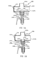
- FIG. 3A there is shown a cross-sectional view of a portion of an improved endotracheal catheter, generally indicated at 200.
- the endotracheal catheter includes a manifold, generally indicated at 204 and a catheter 208.
- the manifold 204 includes a plurality of ports 212a-d.
- a first port 212a is configured for attachment to the proximal end of an artificial airway, such as the hub of an endotracheal tube.
- a second port 212b is typically connected to a pair of ventilator tubes (not shown) by means of an adapter (not shown), in accordance with common practice in the art.
- distal refers generally to the direction of the patient
- proximal refers to the direction of the user.
- each figure is oriented such that the distal (patient) end is toward the top of the page, while the proximal (clinician) end is toward the bottom of the page.
- conditioned inspiratory air is forced through one of the ventilator tubes, through the second port 212b and the first port 212a and into the patient's lungs via the artificial airway. Exhaled air is carried through the first port 212a and then the second port 212b and out through the other ventilator tube.
- the manifold 204 forms part of a ventilation circuit 214 through which respiratory air is cycled.
- a third port 212c is also forming part of the manifold 204 .
- a cap 216 typically covers the third port 212c.
- the cap 216 may be removed from the third port 212c so that oxygenated air is passed by the patient's endotracheal tube, but inspiratory air is not forced into the patient's lungs by means of a completely closed circuit. This situation, commonly called “blow-by,” enables the patient to gradually resume natural or spontaneous breathing.
- the manifold 204 may comprise a fourth port 212d as shown herein.
- the fourth port 212d is disposed generally opposite the first port 212a and is configured to allow the catheter 208 to slide therethrough and into the first port to enable suctioning of the patient. At the completion of suctioning, the catheter 208 is pulled back into the fourth port 212d to prevent interference with the ventilation circuit 214.
- a coupling or adapter 220 Disposed between the wall forming the fourth port 212d and the catheter 208 is a coupling or adapter 220.
- the adapter 220 engages the wall defining the fourth port 212d.
- the adapter 220 engages a collar 224 that closely surrounds the catheter 208 so as to leave a small cylindrical space 226 around the catheter 208.
- the space between the catheter 208 and the collar 224 is between about 0.127 mm (0.005 inches) and about 0.381 mm (0.015 inches).
- Injecting saline solution through the lavage port 228 further removes the secretions from the exterior of the catheter 208 and enhances evacuation by suction in the catheter. This configuration also minimizes the volumes of air and cleaning solution necessary to effect cleaning.
- While the collar 224 configuration shown in FIG. 3A is beneficial, it is still common to have secretions build up on the distal end 208a of the catheter 208. If such build up is not promptly removed, it can interfere with the ability of the catheter to properly suction the patient. It can also serve as a culture medium for pathogens within the closed suction catheter system.
- the present invention enhances the duration that the closed suction catheter system may be used by reducing the amount of pathogens on catheter 208 as disclosed herein.
- a flap 232 is hingedly attached to an annular ring 236 disposed inside the fourth port 212d so as to enable the flap 232 to pivot with respect to the ring to form a self-closing valve member.
- the flap 232 could be attached directly to the wall of the manifold 204 defining the fourth port 212d or to the adapter 220.
- the hinged attachment 240 allows the flap 232 to selectively move while maintaining alignment with the catheter tip, thereby creating a self-closing flap valve.
- the flap 232 is positioned to align with the distal end 208a of the catheter 208 when the catheter is almost completely withdrawn into the collar 224.
- the hinged attachment 240 is sufficiently flexible that suction through the distal end 208a of the catheter 208 will draw the flap 232 proximally from a first, distal position into a second, proximal position, wherein the flap contacts the distal end 208a of the catheter 208.
- the catheter 208 is formed such that a primary aperture 244 is formed in the distal end 208a and one or more lateral apertures 248 positioned slightly proximal from the distal end 208a.
- a primary aperture 244 is formed in the distal end 208a and one or more lateral apertures 248 positioned slightly proximal from the distal end 208a.
- suction through catheter tip aperture 244 is reduced or eliminated.
- the covering of aperture 244 causes increased suction flow in the lateral apertures 248, thereby increasing the evacuation of secretions contained between the outside of the catheter 208 and the interior of the collar 224 via apertures 248. Because each lateral aperture 248 is generally smaller than the distal aperture 244 and because the collar 224 limits airflow to the lateral apertures 248, less air is drawn from the ventilation circuit while simultaneously improving cleaning of the catheter 208.
- the proximal side 232a (i.e., the side opposite the ventilation circuit 214) of the flap 232 is generally planar.
- the proximal side 232a of the flap 232 may form a substantially complete seal with the distal end 208a of the catheter 208 to selectively occlude the catheter 208 from the manifold 200.
- FIG. 3C there is shown a close-up cross-sectional view of the embodiment shown in FIGs. 3A and 3B with a slight modification to the flap 232.
- the flap 232 in FIG. 3C has a channel 252 formed therein on the proximal side 232a.
- the channel 252 prevents the flap 232 from forming an airtight engagement with the distal end 208a of the catheter 208.
- the channel 252 ensures that a measured volume of air will be drawn into the aperture 244 at the distal most end 208 of the catheter.
- the measured volume of air that is drawn in through the channel 252 can have an important effect. Specifically, the air creates turbulent airflow both within the catheter 208 and immediately around its exterior. The turbulent airflow in turn, assists in breaking up agglomerations of mucus and secretions which saline solution alone may not. Thus, the turbulent airflow helps to provide improved cleaning of the distal end 208a of the catheter 208. This is in sharp contrast to many of the prior art devices that have advocated the use of a lavage/cleaning chamber to clean the exterior of the catheter. Because the lavage/cleaning chamber is usually substantially larger than the catheter or because makeup air is not specifically provided, it is difficult to create turbulent airflow within the chamber. Without turbulent airflow, the mucus and other secretions are more difficult to remove from the exterior of the catheter.
- FIG. 3D there is shown yet another variation of the flap 232 shown in FIGs. 3A and 3B.
- the flap 232 Rather than having a channel formed in a proximal side 232a thereof, the flap 232 has an aperture 260 formed therein so as to allow a relatively small amount of air to pass through the flap 232.
- the small hole creates turbulent airflow at the distal end 208a of the catheter 208 and thereby improves cleaning. It is currently believed that an aperture 260 in the flap 232 with a diameter of about 0.76 mm (0.03 inches) is preferred.
- FIG. 3E shows an embodiment similar to those shown in FIGs. 3A through 3D, except that the flap 232 is disposed to engage the distal end 224a of the collar 224 rather than the distal end 208a of the catheter 208. In such a configuration, suction flow can still be achieved through the aperture 244 at the distal end 208a of the catheter 208.
- a source of makeup air will be provided as will be discussed in greater detail herein in reference to FIGS. 4A, 4B, and 4C. This can be accomplished by using either of the flap configurations shown in FIGs. 3C and 3D.
- a small hole can be formed in the collar 224 to facilitate a small amount of makeup air being present to enhance suction flow and to increase turbulence.
- the result is an improved ability to clean the distal end 208a of the catheter 208, while at the same time significantly reducing the amount of air which is withdrawn from the ventilation circuit 214.
- consistent ventilation is provided to the patient and the clinician is able to more easily clean the catheter 208.
- the improved respiratory suction catheter apparatus 300 includes a manifold 304 and a catheter 308.
- the manifold 304 includes a first port 312a, a second port 312b, a third port 312c, and a fourth port 312d.
- This embodiment may further comprise a cap 316 over at least one port, shown on port 312c in this configuration.
- An adapter 320 may be disposed in the fourth port 312d.
- the adapter 320 may be adhesively attached to the manifold 304, or may be a simple force-fit.
- annular ring is not disposed in the manifold 304 independent of the adapter 320. Rather, an annular ring 326 extends inwardly from a distal end 320a of the adapter 320.
- the annular ring 326 defines an aperture or opening 330 through which the catheter 308 can be extended.
- the opening 330 is slightly larger than the exterior of the catheter 308.
- flap 336 Also extending inwardly from the adapter 320 is a flap 336.
- the flap 336 is preferably hingedly attached to either the adapter directly or to the annular ring 326. When no suction is applied to the catheter 308, or when the distal end 308a of the catheter is disposed distally from the flap 336, the flap will generally extend distally from the annular ring 326 and provide virtually no resistance to advancement of the catheter 308.
- flap 336 may benefit from the incorporation mechanism that biases flap 336 in a closed position when the catheter 308 is retracted. Moreover, flap 336 may be formed such that it is biased in this closed position.
- the embodiment in FIGs. 4A through 4C has a makeup air inlet, generally indicated at 350 which is formed in a portion of the wall defining the fourth port 312d of the manifold and the adapter 320.
- the makeup air inlet 350 preferably includes a filter 354 that is selected to substantially prevent cross-contamination between the environment/clinicians and the patient. Disposed adjacent to the filter material is a flexible barrier 358 which forms a one-way valve 360.
- the one-way valve 358 will generally be closed when the catheter 308 is in an extended position, wherein the catheter extends through the opening 330 in the annular ring 326.
- a vacuum will quickly develop on the side of the flap 336 opposite the ventilation circuit 340.
- the vacuum causes the one-way valve 358 to open and allow a supply of makeup air to enter the chamber.
- the makeup air flowing past the flexible one-way valve member 358 helps to create turbulent airflow and facilitate removal of any respiratory secretions on the catheter 308.
- the one-way valve 358 could be configured to provide very little resistance to air inflow, or could be configured to require a substantial vacuum to be present before makeup air is allowed into the area proximal the flap 336.
- the respiratory suction catheter apparatus includes a manifold 404 and a catheter 408 that is moveable through the manifold to suction secretions from a patient's lungs.
- the manifold includes a first port 412a for attachment to an endotracheal tube or other artificial airway, a second port 412b for attachment to the ventilator tubes of a mechanical ventilator, an optional third port 412c that is covered with a cap 416, and an optional fourth port 412d which receives the connector or adapter 420.
- valve 424 Disposed at the distal end 420a of the adapter 420 is a valve 424 in a configuration that is commonly referred to as a duckbill valve.
- the valve 424 is formed by a piece of resilient material that opens as the catheter 408 is advanced therethrough, and closes when the catheter is withdrawn.
- the valve 424 is attached to the adapter 420 by a flexible base 428.
- an air inlet 432 which includes a filter material 436 and a resilient member 440 configured to form a one-way valve 444 similar to that discussed in the previous embodiment.
- a filter material 436 and a resilient member 440 configured to form a one-way valve 444 similar to that discussed in the previous embodiment.
- the valve 424 shown in FIGs. 5A through 5C is substantially advanced in several respects.
- the interior of the valve 424 has helical grooves 450 formed therein.
- the helical grooves 450 help to create turbulent airflow around the distal end 408a of the catheter 408.
- the flexible base 428 is configured to allow the valve 420 to be drawn toward the collar 460 to reduce the size of the cleaning chamber and improve removal of secretions from the exterior of the catheter 408.
- FIG. 5B there is shown a cross-sectional view similar to that shown in FIG. 5A, but with the distal end 408a of the catheter 408 in a retracted position.
- the suction through the catheter works against the flexible base 428 of the valve and draws the valve toward the collar 460.
- a pair of air inlets 470 is disposed at the base 428 of the valve 424 and allows air into the valve.
- valve 424 may return to the position shown in FIG. 5A, except that it will be closed as the catheter 408 remains substantially in the collar until the next use.
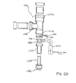
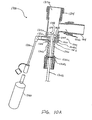
- FIG. 6A there is shown a partial, cross-sectional, exploded, cross-sectional view of a preferred embodiment of an improved endotracheal catheter.
- this exploded assembly comprises a positive end expiratory pressure (“PEEP") or pressure seal 1286 or similar resiliently closing membrane that is disposed within manifold adapter 1284.
- PEEP positive end expiratory pressure
- pressure seal 1286 rests within a cavity defined by manifold adapter 1284.
- manifold adapter 1284 in turn may be inserted within a cavity formed within seal retainer 1282.
- Seal retainer 1282 is also formed to encompass wiper seal 1280 or similar resiliently closing membrane when assembled. This wiper seal 1280 will be discussed in greater detail below.
- valve retainer 1288 presses wiper seal 1280 within the cavity formed in seal retainer 1282.
- valve retainer 1288 preferably comprises a lavage port 1290.
- Lavage port 1290 allows the connection of irrigation housing 1270.
- valve retainer 1288 also prevents valve 1232 from being disposed more proximally than the closed position previously defined.
- valve 1232 further comprises an optional hole 1260 to improve cleaning as discussed herein.
- housing 1200 comprises three ports, port 1212a, 1212b, and 1212d.
- ports 1212a and 1212b may be formed such that they may accommodate swivel connections.
- ports 1212a and 1212b are formed at swivel connection points 1204a and 1204b, respectively, to accommodate swivels 1274a and 1274b, respectively.
- the patient is allowed a greater freedom of movement and less discomfort related to binding, ill-fitting connections.
- manipulation of the assembly by clinicians is more comfortable for the patient.
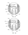
- FIG. 6B shows the pressure seal 1286 firmly seated within manifold adapter 1284. As shown a portion of the exterior surface catheter 1208 is in contact with pressure seal 1286. Moreover, manifold adapter 1284 is shown disposed within seal retainer 1282. Though these portions may be fused together, it is advantageous to releasably connect these portions to allow for greater flexibility and accommodation of different configurations of an improved respiratory suction catheter apparatus.
- valve retainer 1288 presses wiper seal 1280 in a position such that the advancement of catheter 1208 will not dislodge wiper seal 1280. Furthermore, the valve retainer 1288 prohibits valve 1232, preferably the flap valve described herein, from moving to a position more proximal than the closed position. In this configuration, flap valve 1232 is connected to collar 1210 but any other configurations disclosed herein are considered within the scope of the invention as shown.
- flap valve 1232 further comprises an optional hole 1260 formed therein to improve cleaning as previously discussed.
- lavage port 1290 provides an attachment site for irrigation housing 1270. Irrigation housing 1270 may be force fitted or otherwise attached to lavage port 1290 to provide for an additional conduit for irrigation during the cleaning process.
- catheter 1208 has translated through the manifold 1200 such that the distal end 1208a of catheter 1208 is available to enter the respiratory tract of a patient.
- aperture 1244 and optional apertures 1248 may provide a point of suctioning.
- flap valve 1232 has been deflected to an open position to allow the translation of catheter 1208 therethrough.
- wiper seal 1280 contacts at least a portion of the exterior surface of catheter 1208 such that wiper seal 1280 may aide in the cleaning of catheter 1208 during retraction from patient.
- wiper seal 1280 may engage and remain in contact with the portion of an exterior surface of the catheter 1208 during retraction. As catheter 1208 is retracted, wiper seal 1280 will effectively scrape mucus and other secretions from the exterior surface of catheter 1208.
- valve 1232 a partial, exploded, cross-sectional view of the preferred embodiment of a respiratory suction catheter apparatus, valve 1232, including at least one protrusion 1292 extending beyond a planer surface of valve 1232, may increase the effectiveness of cleaning catheter 1208 as is shown in more detail herein with reference to FIG. 6G.
- FIG. 6E a partial, cross-sectional view of a preferred embodiment of a suction catheter apparatus
- the distal tip 1208a is advanced to wiper seal 1280 when catheter 1208 is advanced.
- wiper seal 1280 a portion of the exterior surface of catheter 1208 comes into contact with wiper seal 1280 as shown in FIG. 6F, a partial cross-sectional view of the new preferred embodiment of the respiratory suction catheter apparatus.
- catheter 1208 is advanced and comes into contact with a proximal surface of valve 1232. As previously discussed, this contact with valve 1232 will reduce the suction at aperture 1244 and allow greater suction via apertures 1248, if included, to improve cleaning of catheter 1208.
- catheter 1208 is being advanced at this time, when catheter 1208 is retracted, the view as shown in FIG. 6F will occur again.
- the suction at the distal end 1208a of catheter 1208, occurring through aperture 1244 may assist flap valve 1232 to come into contact and form the closed position as shown in FIG. 6F.
- an optional hole 1260 has been incorporated into flap valve 1232 to improve the cleaning effect after retraction.
- the wiper seal 1280 will scrape mucus and similar secretions from the exterior surface from catheter 1208 during retraction.
- the availability of suction to remove this mucus and secretions improves the cleaning process.
- This arrangement reduces the opportunity for catheter 1208 to transfer mucus or similar secretions onto a distal surface of valve 1232.
- the irrigation housing 1270 attached at lavage port 1290 of valve retainer 1288 provides an opportunity for cleaning solutions to be introduced to help dislodge mucus and similar secretions from the exterior surface of catheter 1208.
- At least one protrusion 1292 on flap valve 1232 namely a protrusion 1292 formed on a proximal surface of flap 1232, when formed on flap 1232, aids in distancing the flap 1232 from catheter 1208 during advancement and retraction.
- at least one protrusion 1292 formed on a proximal surface of flap 1232 may provide the primary point of contact between an exterior surface of catheter 1208 and the flap 1232 such that when catheter 1208 is retracted, protrusion 1292 comes into contact with catheter 1208. In this configuration, less mucus and similar secretions are scraped by the planar surface of flap 1232.
- valve 1232 This configuration reduces the likelihood that catheter 1208 will transfer mucus or similar secretions onto a distal surface of valve 1232. Therefore, more of the mucus and similar secretions are allowed to enter the cleaning chamber defined by valve 1232 in a closed position and pressure seal 1286 such that mucus and similar secretions may be cleaned during the cleaning process. Importantly, the inclusion of wiper seal 1280 will allow a significant portion of the mucus and similar secretions to be dislodged during retraction of catheter 1208 through manifold 1200.
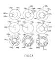
- wiper seal 1280 a variety of configurations in the formation of wiper seal 1280 are available. As shown in FIG. 6H, a cross-sectional, top view of several embodiments of wiper seal 1280, a variety of shapes and configurations may be used independently or in combination to form at least one wiper seal 1280.
- wiper seal 1280a as shown in FIG. 6H comprises a circular surface 1281a wherein a through hole 1287a, formed in a circular shape in this configuration, has been formed therein. It is preferable that the diameter in the through hole 1287a is slightly less than or equal to the outer diameter of catheter 1208 (not shown) such that the exterior surface of catheter 1208 (not shown) will contact a significant portion of the interior edge 1283a of surface 1281a of wiper seal 1280a.
- the wiper seal surface 1281b is formed such that a through hole 1287b is formed. Additionally, at least one slit 1289b is formed in surface 1281b to accommodate varying diameters of catheters that are advanced and retracted by through hole 1287b. As before, the advancement and retraction of catheter 1208 will come into contact with a significant portion of the edge 1283b of wiper seal surface 1281b.
- wiper seal 1280c comprises a surface 1281c that forms a similar through hole 1287c. Moreover, this embodiment shows a significant plurality of slits 1289c formed within surface 1281c of wiper seal 1280c. In this configuration, the inner edge 1283c of surface 1281c of wiper seal 1280c remains extremely flexible and may accommodate the advancement and retraction of catheters of diameters of varying greater variance in size. As before, it is better for the diameter of through hole 1287c to be less than or equal to the exterior diameter of a catheter 1208 (not shown) that will be advanced and retracted therethrough.
- the surface 1281d of wiper seal 1280d comprises an S-shaped slit 1289d formed therein.
- the advancement and retraction of the catheter 1208 (not shown) will expand and create a through hole through S-shape slit 1289d.
- wiper seal 1208e comprises a surface 1281e with a straight slit 1289e therein.
- a catheter 1208 (not shown) will separate slit 1289e and allow for the retraction and advancement of catheter 1208 (not shown).
- wiper seal 1280f comprises a surface 1281 f formed such that a through hole 1287f is formed therein.
- the inner edge 1283f of surface 1281f will engage in contact and catheter 1208 (not shown) as it passes therethrough.
- surface 1281f of wiper seal 1280f further comprises at least one notch 1285f formed about the inner edge 1283f of wiper seal 1280f. Each notch 1285f allows for the accommodating varying sizes of catheters 1208 (not shown) by allowing for a slightly greater diameter catheter 1208 to advance and retract therethrough.
- wiper seal 1280g comprises a surface 1281g formed such that a through hole 1287g is formed therein. The inner edge 1283g of surface 1281g will engage in contact and catheter 1208 (not shown) as it passes therethrough.
- surface 1281g of wiper seal 1280g further comprises at least one cutout 1291g formed in surface 1281g. As shown, wiper seal 1280g comprises a plurality of cutouts 1291g to form a wagon-wheel appearance.
- wiper seal 1280h a configuration similar to wiper seal 1280a is shown. Specifically, wiper seal 1280h comprises a surface 1281h a through hole 1287h formed therein. This wiper seal 1280h is formed such that an inner edge 1283h of wiper seal 1280h may interact with a catheter 1208 (not shown) as it is advanced or retracted therethrough. Of note, wiper seal 1280h is shown in a cross-sectional view such that a sponge like or similar coarser material may be used in wiper seal 1280h.
- wiper seal 1280i comprises a surface 1281i formed such that a through hole 1287i is formed therein and creates an inner edge 1283i in wiper seal 1280i to contact a catheter 1208 (not shown) during advancement nor retraction.
- This cross sectional view shows that brush like or similar materials may be used in the formation of wiper seal 1280i.
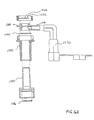
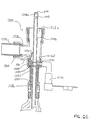
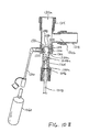
- FIG. 7 there is shown a partial, cross-sectional, exploded, cross-sectional view of an embodiment of an improved endotracheal catheter made in accordance with the principles of the invention.
- this exploded assembly comprises a pressure seal 1286 or similar resiliently closing membrane that is disposed within manifold adapter 1284.
- the pressure seal 1286 rests within a cavity defined by manifold adapter 1284.
- manifold adapter 1284 in turn may be inserted within a cavity formed within seal retainer 1282.
- Seal retainer 1282 is also formed to encompass wiper seal 1280 or similar resiliently closing membrane when assembled.
- lavage port 1290 is disposed between wiper seal 1280 and pressure seal 1286 to form the cleaning chamber in this embodiment.
- Lavage port 1290 allows the connection of irrigation housing 1270.
- this configuration allows for an assembly without the need for a valve as shown in the other embodiments.
- the respiratory suction catheter apparatus 600 includes a manifold 604 and a catheter 608 that is moveable through the manifold.
- the manifold 604 includes a first port 612a for connection to the hub of an endotracheal tube, a second port 612b for connection (via ventilator tubes) to a mechanical ventilator, and an optional third port 612c and cap 616 which can be used for blow-by.
- the fourth port 612d is different from those discussed previously because it has a shroud 620 placed therein.
- the shroud 620 is attached to a plunger 624 so as to allow the user to move the shroud between a first position adjacent the sidewall of the fourth port 612d (FIG. 8A) and a second position (FIG. 8B) wherein the shroud is disposed approximately at the center of port 612d.
- the shroud 620 will typically be moved into the first position so that it does not interfere with advancement of the catheter 608 through the manifold 604. Once suctioning has been completed, the catheter 608 is withdrawn into the collar 634.
- the plunger 624 is then pressed so as to move the shroud 620 over the distal end 634a of the collar 634 to cover the distal end 608a of the catheter 608.
- the catheter 608 will then be advanced toward the distal end 620a of the shroud 620.
- Lavage/cleaning solution will then be applied through the lavage port 640 while suction is applied.
- a small gap can be formed between the shroud 620 and the collar 634 to ensure turbulent airflow into the distal end 608a of the catheter 608.
- grooves or some other pattern may be formed in the shroud to encourage turbulent airflow.
- a valve member may be included to allow for makeup air in a similar manner as discussed with several of the embodiments above.
- FIG. 8A and FIG. 8B show an apparatus 600 that benefits from the inclusion of wiper seal 680.
- wiper seal 680 acts to scrape mucus and similar secretions from catheter 608 during retraction.
- FIG. 9A there is shown a top view of flap valve 932, the rings shown jointly as 936 and associated structure.
- This flap valve 932 may be used in the embodiments shown.
- the flap valve 932 is attached to the ring 936 by two arms 948, each forming an attachment point 940.
- the opposite end 932c of the flap 932 engages a catch 964 or similar locking mechanism that is attached to the ring 936 by an arm 968.
- the catch 964 effectively locks the flap 932 in a proximal position until the user forcibly advances the catheter in a distal direction, causing the catch to release the flap valve 932.
- a single arm 948 could be used with the flap 932, and multiple catches 964 could be used.
- a single ring could be used rather than the rings 936a to support the flap 932 and the catch 964.
- modifications can be made the flap 932d to provide other benefits.
- a pair of arms 948a attaches the flap 932d to the ring 936a.
- the arms 948a could be configured to bias the flap 932d into the closed position.
- This flap 932d further comprises at least one protrusion 992a, a pair of protrusions 992a are shown herein, to aid in the retention of mucus and secretions until the catheter enters the cleaning chamber as discussed herein.
- the flap 932d is generally circular, but has two rounded projections 950a that extend outwardly and are spaced approximately 90 degrees apart.
- the projections serve two important purposes. First, even if the generally circular portion of the flap 932d were slightly smaller than the distal opening of the endotracheal tube (not shown), the projections 950a would prevent the flap from entering the endotracheal tube. Second, the projections 950a would cause the flap to align for airflow to continue to the patient without lying flat to cover any passage which might interfere with airflow to or from the patient.
- the aperture 960a that is formed in the generally circular portion of the flap 932d. As shown, the aperture 960a is between about 0.76 mm (0.03 inches) and about 1.02 mm (0.04 inches) in diameter. While shown as being circular or disk-shaped, those skilled in the art will appreciate, in light of the present disclosure, that other shaped apertures could also be used.
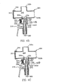
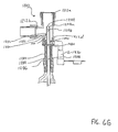
- FIG. 10A shows a cross-sectional view of an embodiment of an endotracheal catheter system 1300.
- the endotracheal catheter system 1300 includes a manifold, generally indicated at 1304 which forms a fitting for connecting the endotracheal catheter system 1300 to the artificial airway (i.e. endotracheal tube) of a patient.
- the endotracheal catheter system 1300 also includes an elongate catheter 1308.
- the manifold 1304 includes a first port 1312a, a second port 1312b, and a third port 1312c.
- the first port 1312a is configured to engage an artificial airway, such as an endotracheal tube.
- the second port 1312b provides inspiratory and expiratory airflow to and from the patient.
- a Y-shaped adapter is attached to the second port 1312b.
- many configurations are used in the clinical setting and those skilled in the art will appreciate the different combinations that are available.
- the third port 1312c is disposed opposite the first port 1312a and aligned so that the catheter 1308 can pass through the third port, through the manifold 1304 and through the first port into the artificial airway.
- the first and second ports 1312a and 1312b may also have swivel structures 1314 to enable the manifold 1304 to swivel with respect to adjoining structures and thereby improve patient comfort.
- a coupling or adapter 1320 Connected to the third port 1312c is a coupling or adapter 1320.
- the adapter 1320 engages the wall defining the third port 1312c.
- the inner surface of the adapter 1320 forms a chamber about the distal end 1308a of the catheter 1308. This chamber assists in cleaning the distal end of the catheter in a manner that will be discussed more fully below.
- a collar 1324 Disposed adjacent to the distal end 1320a of the adapter 1320 is a collar 1324 which has a frustoconical bore 1328 extending therethrough. Those skilled in the art will appreciate that the collar 1324 could be formed integrally with the adapter 1320 if desired.
- the collar 1324 helps to channel the saline solution along the catheter 1308, through the first port 1312a and into the artificial airway.
- the distal end 1324a of frustoconical bore forms an orifice in the distal end of the collar 1324.
- a flap 1340 supported by a support ring 1344 disposed in the third port 1312c selectively engages the orifice to substantially occlude the orifice when the two are engaged.
- the flap 1340 preferably has one or more holes 1348 formed therein to allow a small amount of air through the flap valve.
- the flap valve 1340 may be biased in the closed position, or may be drawn into the closed position by suction through the catheter 1308.
- a wiper seal 1352 Disposed at the opposing, proximal end of the collar 1324 is a wiper seal 1352.
- a narrowed portion 1320b of the adapter 1320 supports the wiper seal 1352.
- the wiper seal removes major secretions.
- the adapter 1320 extends proximally and forms a cleaning chamber. Disposed adjacent a proximal end 1320c of the adapter 1320 is a pressure seal 1356.
- the object of the pressure seal 1356 is to remove secretions from the exterior of the catheter 1308 as it is withdrawn from the artificial airway of the patient.
- the pressure seal 1356 will typically have a smaller diameter opening so that the pressure seal 1356 more closely engages the exterior of the catheter 1308 than the wiper seal 1352.
- FIG. 10B there is shown a side cross-sectional view of the endotracheal catheter assembly 1300 in which the catheter 1308 has been withdrawn through the manifold 1304 into a cleaning position.
- the flap 1340 closes-either due to a bias or the suction through the catheter-to occlude the opening in the collar 1324.
- the distal end 1308a of the catheter is wiped by the wiper seal 1352 so that most secretions thereon are removed.
- the secretions that are removed by the wiper seal 1352 are then carried through the catheter 1308.
- a bottle 1360 is attached to the lavage port 1330 and a cleaning liquid (typically saline solution) is supplied through the side opening 1332 in the collar 1324.
- the cleaning liquid flows around the distal end 1308a of the catheter 1308, indicated by arrow 1364, and cleans those secretions which were not removed by the wiper seal 1352 from the distal end of the catheter.
- the holes 1348 in the flap 1340 allow a small amount of air into the catheter, thereby facilitating removal of the secretions.
- a make-up air valve could be disposed on the side of the adapter 1320 to allow the inflow of additional air.
- the seals and valves can be comprised of such synthetic resins as polyurethanes, ethylene vinyl acetate copolymers, polyvinyl chlorides, polysilicones, polyamides, such as nylon, polyethylene, including those of the high density, low density, intermediate density and linear low density variety, ethylene ⁇ -olefin copolymers (such as ethylene propylene copolymers), polyesters, polycarbonates, acrylonitrile-butadiene-styrene copolymers, polyether-polyester copolymers, and polyether polyamide copolymers are desirable. Further desirable are low pressure, relatively soft or flexible polymeric materials, such as thermoplastic polymers including thermoplastic elastomers.
- Injection molded medical grade synthetic resinous materials are preferable for such internal components.
- Suitable resins include Pebax® by Atochem North America, Inc., Philadelphia Pennsylvania. Most preferred are the Pebax® 33 polyamide/polyether polymers, such as Pebax® 3533 SA 00 polymers.
- Such polymers may be characterized by a Shore D, ASTM D2240, hardness of about 35, a Shore A, ASTM D2240, hardness of about 85, and a flexural modulus, ASTM D790, of about 19995500 Pa (2,900 PSI), a softening point, ASTM D1525, of approximately 73°C (165°F) and a melting point of between about 109°C (228°F) and about 154°C (309°F).
- Pebax® 5533 SA 00 polyether block amide polymer characterized by a Shore D, ASTM D2240, hardness of about 55, a flexural modulus, ASTM D790, of about 165480000 Pa (24,000 PSI), a softening point, ASTM D1525, of approximately 144°C (291°F), and a melting point of between about 128°C (262°F) and about 170°C (338°F).
- Thermoplastic elastomeric polymers which render excellent results as the internal components for use in the invention further include those sold under the Monprene® name, a trademark of QST, Inc., including Monprene® MP-2870M, having a Shore A hardness, ASTM D2240, of about 70; Santoprene® name, a trademark of Advanced Elastomer Systems, including Santoprene® MP-2870M, having a Shore D hardness, ASTM D2240, of about 40; polyurethane (polyether) elastomers, such as those sold under the PellathaneTM name, a trademark of Dow Plastics, including Pellathane® 2363-80AE, having a Shore A hardness, ASTM D2240, of about 85; ethylene vinyl acetate polymer sold under the Elvax® name, a trademark of E.I.
- du Pont Packaging & Industrial Polymers including Elvax® 150 (33% vinyl acetate) and Elvax® 360 (25% vinyl acetate), Elvax® 450 (18% vinyl acetate) or Elvax® 750 (9% vinyl acetate); low density polyethylene polymers, such 3447500 Pa (500 PSI); the low density polyethylenes sold under the Petrothene® trademark by Equistar Chemicals, L.P., such as Petrothene® NA 270-000 low density polyethylene polymer; polyvinyl chlorides commercially available under the UnichemTM trademark by Colorite Plastics Company, such as UnichemTM 7811G-015 polyvinyl chloride polymer, UnichemTM 8511G-015 flexible polyvinyl chloride polymer, UnichemTM 6511G-015 flexible polyvinyl chloride polymer; the styrene ethylene butylene styrene block copolymers commercially available under the KratonTM trademark by Shell Chemical Company, such as the KratonTM G-7705 st
- the cleaning of the distal end of a catheter may be enhanced while minimizing or eliminating the air drawn from the ventilation circuit of the patient.
Abstract
Description
Claims (6)
- A respiratory suction system (1200) comprising:characterised byan elongate catheter (1208);a manifold (1204) for forming a part of a ventilation circuit having a passageway (1212d) into which the catheter may be advanced;at least one pressure seal (1286) configured for contacting the catheter and disposed within the manifold having a cross area sufficient to engage the catheter and maintain pressure in the manifold; anda lavage port (1290);
at least one resilient seal (1280) disposed distal to the pressure seal within the manifold and configured for contacting the catheter, a distal surface of the resilient seal having a cross area sufficient to wipe the catheter when the catheter is retracted from the manifold; and
the lavage port (1290) is in fluid communication with the manifold and disposed between the resilient seal and the pressure seal. - The respiratory suction system of Claim 1, wherein the resilient seal is a cylindrical disk.
- The respiratory suction system of Claim 2, wherein the cylindrical disk has an aperture formed therein.
- The respiratory suction system of Claim 1, wherein the catheter is encased within a collapsible sheath.
- The respiratory suction system of Claim 1, wherein at least one seal is composed of a medical grade synthetic resin selected from polyurethanes, ethylene vinyl acetate copolymers, polyvinyl chlorides, polyamide/polyethers, polysilicones, polyamides, polyethylene, ethylene α-olefin copolymers, polyesters, polycarbonates, acrylonitrile-butadiene-styrene copolymers and polyether polyester copolymers.
- The respiratory suction system of Claim 1, wherein at least one seal is composed of a polyether block amide.
Applications Claiming Priority (3)
| Application Number | Priority Date | Filing Date | Title |
|---|---|---|---|
| US471317 | 1999-12-23 | ||
| US09/471,317 US6543451B1 (en) | 1999-12-23 | 1999-12-23 | Endotracheal catheter and manifold assembly with improved seal and valve |
| PCT/US2000/034638 WO2001045779A1 (en) | 1999-12-23 | 2000-12-20 | Endotracheal catheter and manifold assembly with seal and valve |
Publications (2)
| Publication Number | Publication Date |
|---|---|
| EP1239909A1 EP1239909A1 (en) | 2002-09-18 |
| EP1239909B1 true EP1239909B1 (en) | 2005-08-03 |
Family
ID=23871150
Family Applications (1)
| Application Number | Title | Priority Date | Filing Date |
|---|---|---|---|
| EP00986621A Expired - Lifetime EP1239909B1 (en) | 1999-12-23 | 2000-12-20 | Endotracheal catheter and manifold assembly with seal and valve |
Country Status (12)
| Country | Link |
|---|---|
| US (1) | US6543451B1 (en) |
| EP (1) | EP1239909B1 (en) |
| JP (1) | JP4741772B2 (en) |
| KR (1) | KR100701116B1 (en) |
| AT (1) | ATE300969T1 (en) |
| AU (1) | AU774793B2 (en) |
| BR (1) | BR0016691B1 (en) |
| CA (1) | CA2395470C (en) |
| DE (1) | DE60021762T2 (en) |
| MX (1) | MXPA02006287A (en) |
| NO (1) | NO20023044L (en) |
| WO (1) | WO2001045779A1 (en) |
Cited By (8)
| Publication number | Priority date | Publication date | Assignee | Title |
|---|---|---|---|---|
| WO2011020985A1 (en) | 2009-08-20 | 2011-02-24 | Smiths Medical International Limited | Ventilation and suction systems and assemblies |
| US8628056B2 (en) | 2009-02-02 | 2014-01-14 | Aptargroup, Inc. | Dual sealing system for use with a probe |
| WO2019077292A1 (en) | 2017-10-20 | 2019-04-25 | Smiths Medical International Limited | Suction catheter assemblies |
| WO2020178540A1 (en) | 2019-03-02 | 2020-09-10 | Smiths Medical International Limited | Suction catheter assemblies and assemblies including a suction catheter assembly |
| WO2021079079A1 (en) | 2019-10-22 | 2021-04-29 | Smiths Medical International Limited | Connectors and assemblies |
| WO2021224585A1 (en) | 2020-05-04 | 2021-11-11 | Smiths Medical International Limited | Closed-system suction catheter assemblies and methods |
| WO2022023687A1 (en) | 2020-07-28 | 2022-02-03 | Smiths Medical International Limited | Closed-system suction catheter assemblies |
| WO2022238668A1 (en) | 2021-05-10 | 2022-11-17 | Smiths Medical International Limited | Suction catheter assemblies |
Families Citing this family (55)
| Publication number | Priority date | Publication date | Assignee | Title |
|---|---|---|---|---|
| EP1272244B9 (en) * | 2000-04-06 | 2004-10-20 | Unomedical a/s | A coupling arrangement |
| ES2293974T3 (en) * | 2000-04-06 | 2008-04-01 | Unomedical A/S | DISTRIBUTOR. |
| DK174620B1 (en) * | 2000-04-06 | 2003-07-28 | Maersk Medical As | A valve assembly |
| US6769430B1 (en) * | 2000-10-31 | 2004-08-03 | Kimberly-Clark Worldwide, Inc. | Heat and moisture exchanger adaptor for closed suction catheter assembly and system containing the same |
| US7204252B2 (en) * | 2001-12-21 | 2007-04-17 | Eidon, Llc | Surface energy assisted fluid transport system |
| US6588427B1 (en) * | 2002-02-25 | 2003-07-08 | Kimberly-Clark Worldwide, Inc. | Heat and moisture exchanger adapter to closed suction catheter assembly and system having improved catheter cleaning |
| US7490604B2 (en) * | 2002-03-15 | 2009-02-17 | C. R. Bard, Inc. | Endotracheal surfactant distribution system |
| US7191782B2 (en) * | 2003-05-06 | 2007-03-20 | Kimberly-Clark Worldwide, Inc. | Respiratory suction catheter apparatus configured for releasable attachment with an artificial airway structure |
| US7556041B2 (en) * | 2003-05-06 | 2009-07-07 | Kimberly-Clark Worldwide, Inc. | Respiratory apparatus having an introduction section configured for releasable attachment with a respiratory instrument |
| US7263997B2 (en) * | 2003-05-06 | 2007-09-04 | Kimberly-Clark Worldwide, Inc | Respiratory apparatus having an instrument introduction section and manifold |
| US7188623B2 (en) * | 2004-07-07 | 2007-03-13 | Egret Medical Products, Inc. | Suction catheter assembly |
| US20060278235A1 (en) * | 2005-06-14 | 2006-12-14 | White Steven C | Tracheal tube with above the cuff drainage |
| US8834407B2 (en) * | 2006-01-20 | 2014-09-16 | Medline Industries, Inc. | Covered yankauer suction device and methods of using same |
| US7775206B2 (en) | 2006-06-01 | 2010-08-17 | Egret Medical Products, Inc. | Neonate suction catheter assembly |
| US20070296125A1 (en) * | 2006-06-22 | 2007-12-27 | Joel Colburn | Thin cuff for use with medical tubing and method and apparatus for making the same |
| US8434487B2 (en) | 2006-06-22 | 2013-05-07 | Covidien Lp | Endotracheal cuff and technique for using the same |
| US8196584B2 (en) | 2006-06-22 | 2012-06-12 | Nellcor Puritan Bennett Llc | Endotracheal cuff and technique for using the same |
| US20070295337A1 (en) * | 2006-06-22 | 2007-12-27 | Nelson Donald S | Endotracheal cuff and technique for using the same |
| US20080053454A1 (en) * | 2006-09-01 | 2008-03-06 | Nellcor Puritan Bennett Incorporated | Endotracheal tube including a partially inverted cuff collar |
| US8684175B2 (en) | 2006-09-22 | 2014-04-01 | Covidien Lp | Method for shipping and protecting an endotracheal tube with an inflated cuff |
| US8561614B2 (en) * | 2006-09-28 | 2013-10-22 | Covidien Lp | Multi-layer cuffs for medical devices |
| US20080078401A1 (en) * | 2006-09-29 | 2008-04-03 | Nellcor Puritan Bennett Incorporated | Self-sizing adjustable endotracheal tube |
| US8307830B2 (en) | 2006-09-29 | 2012-11-13 | Nellcor Puritan Bennett Llc | Endotracheal cuff and technique for using the same |
| US20080078405A1 (en) * | 2006-09-29 | 2008-04-03 | Crumback Gary L | Self-sizing adjustable endotracheal tube |
| US8807136B2 (en) * | 2006-09-29 | 2014-08-19 | Covidien Lp | Self-sizing adjustable endotracheal tube |
| US20080078399A1 (en) | 2006-09-29 | 2008-04-03 | O'neil Michael P | Self-sizing adjustable endotracheal tube |
| US7950393B2 (en) * | 2006-09-29 | 2011-05-31 | Nellcor Puritan Bennett Llc | Endotracheal cuff and technique for using the same |
| US7625207B2 (en) * | 2006-12-15 | 2009-12-01 | Kimberly-Clark Worldwide, Inc. | Yankauer suction device with sleeve and wiper |
| GB0701315D0 (en) * | 2007-01-24 | 2007-03-07 | Smiths Group Plc | Medico-surgical devices |
| US20080210243A1 (en) * | 2007-03-02 | 2008-09-04 | Jessica Clayton | Endotracheal cuff and technique for using the same |
| US20080215034A1 (en) * | 2007-03-02 | 2008-09-04 | Jessica Clayton | Endotracheal cuff and technique for using the same |
| US8750978B2 (en) * | 2007-12-31 | 2014-06-10 | Covidien Lp | System and sensor for early detection of shock or perfusion failure and technique for using the same |
| US20090229601A1 (en) * | 2008-03-13 | 2009-09-17 | Humberto Aguilar | Intubating Airway Device |
| US20090254062A1 (en) * | 2008-04-03 | 2009-10-08 | Mcglothlin Mark W | Infusion catheters with slit valves and of simplified construction |
| US20090301480A1 (en) * | 2008-06-09 | 2009-12-10 | Mamdouh Elsakka | Diagnostic sample collection system and method of use |
| US8215306B2 (en) | 2008-12-12 | 2012-07-10 | Kimberly-Clark Worldwide, Inc. | Respiratory access port assembly with push button lock and method of use |
| US20100147296A1 (en) * | 2008-12-12 | 2010-06-17 | John Brewer | Port Sealing Cartridge for Medical Ventilating and Aspirating Devices |
| US20100147312A1 (en) * | 2008-12-12 | 2010-06-17 | John Brewer | Respiratory Access Port Assembly With Pin Lock and Method of Use |
| US8307829B2 (en) * | 2008-12-23 | 2012-11-13 | Kimberly-Clark Worldwide, Inc. | Respiratory access assembly with rotating lock and method |
| DK2393538T3 (en) | 2009-02-06 | 2017-11-27 | Endoclear Llc | Devices for cleaning endotracheal tubes |
| US8256422B2 (en) * | 2009-05-15 | 2012-09-04 | Kimberly-Clark Worldwide, Inc | Respiratory access port assembly with passive lock and method of use |
| US8590534B2 (en) * | 2009-06-22 | 2013-11-26 | Covidien Lp | Cuff for use with medical tubing and method and apparatus for making the same |
| EP2902066B1 (en) | 2010-03-29 | 2021-03-10 | Endoclear LLC | Airway cleaning and visualization |
| KR101024340B1 (en) * | 2010-10-21 | 2011-03-23 | 재단법인차세대융합기술연구원 | Medical suction device |
| US10349821B2 (en) * | 2011-03-01 | 2019-07-16 | Sanovas Intellectual Property, Llc | Cleaning system for medical imaging device |
| US9078987B2 (en) | 2011-12-23 | 2015-07-14 | Avent, Inc. | Clutch brake assembly for a respiratory access port |
| US8657800B2 (en) * | 2012-05-24 | 2014-02-25 | Pacific Hospital Supply Co., Ltd. | Suction device having a rotary switch |
| US20130312756A1 (en) * | 2012-05-24 | 2013-11-28 | Pacific Hospital Supply Co., Ltd. | Airtight suction device and air supply assembly thereof |
| US20140166002A1 (en) * | 2012-12-16 | 2014-06-19 | Pacific Hospital Supply Co., Ltd. | Joint of sputum suction tube |
| CN206045111U (en) * | 2014-08-08 | 2017-03-29 | 康尔福盛2200公司 | Closed intake guide system |
| CN106474614B (en) * | 2015-09-02 | 2019-08-16 | 旭邦医疗器材有限公司 | For taking out the attachment base of phlegm pipe |
| EP3165250A1 (en) * | 2015-11-05 | 2017-05-10 | Vitaltec Corporation | Connecting base for suction catheters |
| KR101787040B1 (en) | 2015-12-24 | 2017-10-19 | 강원대학교산학협력단 | Structure combined catheter and catheter device |
| CN108175919A (en) * | 2018-02-12 | 2018-06-19 | 浙江简成医疗科技有限公司 | A kind of extension tube for being used to connect laryngeal mask |
| CN111658939B (en) * | 2020-05-19 | 2023-10-03 | 中国科学院合肥物质科学研究院 | Intelligent central suction device for preventing tube drawing from splashing and application method thereof |
Citations (2)
| Publication number | Priority date | Publication date | Assignee | Title |
|---|---|---|---|---|
| WO2001024862A1 (en) * | 1999-10-05 | 2001-04-12 | Ballard Medical Products | Retaining plug for endotracheal catheter and manifold assembly and method of use |
| WO2001041855A1 (en) * | 1999-12-13 | 2001-06-14 | Ballard Medical Products | Endotracheal catheter and manifold assembly with valve |
Family Cites Families (88)
| Publication number | Priority date | Publication date | Assignee | Title |
|---|---|---|---|---|
| GB810517A (en) | 1956-09-17 | 1959-03-18 | British Oxygen Co Ltd | Connectors for endotracheal and like tubes |
| US3831629A (en) | 1972-01-24 | 1974-08-27 | Halkey Roberts Corp | Check valve |
| US3834388A (en) | 1973-01-29 | 1974-09-10 | Cenco Medical Health Supply Co | Suction control arrangement for a suction catheter |
| US3902500A (en) | 1974-03-01 | 1975-09-02 | Gale E Dryden | Endotracheal catheter with means for positive ventilation and sterile technique |
| US3937220A (en) | 1974-03-04 | 1976-02-10 | International Paper Company | Sterile aspiration catheter |
| US3991762A (en) | 1974-09-30 | 1976-11-16 | Radford F Richard | Aspirating device for patient ventilation apparatus |
| US4015336A (en) | 1975-07-01 | 1977-04-05 | Johnson W Grant | Valve for an oral evacuator system |
| US4047527A (en) | 1975-11-21 | 1977-09-13 | Kelsen Arthur F | Oral syringe |
| US4193406A (en) | 1978-09-18 | 1980-03-18 | Jinotti Walter J | Dual purpose catheter |
| US4351328A (en) | 1980-03-27 | 1982-09-28 | Sontek Industries, Inc. | Simultaneous respiration and endotracheal suctioning of a critically ill patient |
| US4468224A (en) | 1982-01-28 | 1984-08-28 | Advanced Cardiovascular Systems, Inc. | System and method for catheter placement in blood vessels of a human patient |
| SE434703B (en) | 1982-02-23 | 1984-08-13 | Gambro Engstrom Ab | DEVICE FOR CONNECTING AN ANGOSIS OR RESPIRATORY DEVICE TO A PATIENT |
| DE3222539C2 (en) | 1982-06-16 | 1984-07-26 | Drägerwerk AG, 2400 Lübeck | Suction adapter and suction device set using this adapter |
| US4595005A (en) | 1984-02-08 | 1986-06-17 | Jinotti Walter J | Dual-purpose catheter |
| US4573965A (en) | 1984-02-13 | 1986-03-04 | Superior Plastic Products Corp. | Device for draining wounds |
| US4574173A (en) | 1984-05-04 | 1986-03-04 | Warner-Lambert Company | Device for RF welding an IV tube to a catheter lumen |
| SE449565C (en) | 1984-06-28 | 1990-01-04 | Gambro Engstrom Ab | ANTICOS AND / OR RESPIRATOR EQUIPMENT INCLUDING A HUMIDIFICATION AND / OR GAS CHAMBER |
| US4569344A (en) | 1984-07-23 | 1986-02-11 | Ballard Medical Products | Aspirating/ventilating apparatus and method |
| US5277177A (en) | 1984-07-23 | 1994-01-11 | Ballard Medical Products | Single use medical aspirating device and method |
| US5215522A (en) | 1984-07-23 | 1993-06-01 | Ballard Medical Products | Single use medical aspirating device and method |
| GB8419510D0 (en) | 1984-07-31 | 1984-09-05 | Smiths Industries Plc | Tracheostomy tube assemblies |
| US4573979A (en) | 1984-08-23 | 1986-03-04 | Innovative Surgical Products, Inc. | Irrigation/aspiration tip |
| DE3525191C1 (en) | 1985-07-15 | 1986-10-23 | Peter von Berg Extracorporale Systeme - Medizintechnik GmbH, 8011 Kirchheim | Flow control device |
| US4705073A (en) | 1986-04-23 | 1987-11-10 | Advanced Medical Devices, Inc. | Molded plastic gate valve and sealing means therefor |
| GB2199630A (en) | 1986-12-01 | 1988-07-13 | Portex Inc | Plug |
| US4838255A (en) | 1987-03-11 | 1989-06-13 | Ballard Medical Products | Neonatal closed system for involuntary aspiration and ventilation, and method |
| US5107829A (en) | 1987-03-11 | 1992-04-28 | Ballard Medical Products | Neonatal closed system for involuntary aspiration and ventilation, and method |
| US4834726A (en) | 1987-03-11 | 1989-05-30 | Ballard Medical Products | Medical ventilating and aspirating apparatus and methods |
| US4929426A (en) | 1987-11-02 | 1990-05-29 | Biologix, Inc. | Portable blood chemistry measuring apparatus |
| GB2213384B (en) | 1988-01-09 | 1991-12-18 | Smiths Industries Plc | Tracheal tube fittings and assemblies |
| US5582165A (en) | 1988-02-28 | 1996-12-10 | Bryan; James F. | Pre-assembled sealed, sheathed catheters and related valve elements with quick disconnect means for endotracheal suctioning |
| USD312880S (en) | 1988-03-04 | 1990-12-11 | Bodai Balazs I | Neonatal suction valve |
| US5088486A (en) | 1990-04-11 | 1992-02-18 | Jinotti Walter J | Closed system reusable dual purpose catheter |
| US5140983A (en) | 1990-04-11 | 1992-08-25 | Jinotti Walter J | Multi purpose catheter assembly |
| US5125893A (en) | 1990-04-16 | 1992-06-30 | Dryden Gale E | Suction catheter with wall lumen for irrigation |
| US5073164A (en) | 1990-05-02 | 1991-12-17 | Hollister William H | Suction catheter |
| US5083561B1 (en) | 1990-06-14 | 1993-05-18 | D. Russo Ronald | Tracheal suction catheter |
| US5213096A (en) | 1990-06-18 | 1993-05-25 | Gambro Engstrom Ab | Apparatus for connecting a patient to breathing devices, the apparatus including a bacteria filter and gas sampling means |
| US5139018A (en) | 1990-07-24 | 1992-08-18 | Superior Healthcare Group, Inc. | Patient ventilating apparatus with aspirating catheter |
| US5060646A (en) | 1990-09-10 | 1991-10-29 | ||
| US5230332A (en) | 1990-10-22 | 1993-07-27 | Ballard Medical Products | Methods and apparatus for a micro-tracheal catheter hub assembly |
| US5158569A (en) | 1990-12-21 | 1992-10-27 | Ballard Medical Products | Catheter placement locking and sealing device |
| GB9100147D0 (en) | 1991-01-04 | 1991-02-20 | Smiths Industries Plc | Tracheal tube assemblies and liners |
| US5134996A (en) | 1991-01-09 | 1992-08-04 | Smiths Industries Medical Systems, Inc. | Inspiration and expiration indicator for a suction catheter |
| WO1994019044A1 (en) | 1991-01-28 | 1994-09-01 | Genesis Medical, Ltd. | Insufflating/suctioning valve |
| US5191881A (en) | 1991-01-28 | 1993-03-09 | Genesis Medical, Ltd. | Insufflating/suctioning valve |
| US5368017A (en) | 1991-04-01 | 1994-11-29 | Sorenson Laboratories, Inc. | Apparatus for ventilating and aspirating |
| US5325851A (en) | 1991-04-01 | 1994-07-05 | Sorenson Laboratories, Inc. | Apparatus and method for ventilating and aspirating |
| US5255676A (en) | 1991-11-08 | 1993-10-26 | Russo Ronald D | Safety sealed tracheal suction system |
| DE4208912C1 (en) | 1992-03-20 | 1993-05-19 | Rudolf 5300 Bonn De Schoen | |
| US5337780A (en) | 1992-10-19 | 1994-08-16 | Sherwood Medical Company | Suction control valve |
| US5333607A (en) | 1992-10-19 | 1994-08-02 | Sherwood Medical Company | Ventilator manifold with accessory access port |
| US5309902A (en) | 1992-10-19 | 1994-05-10 | Sherwood Medical Company | Respiratory support system and suction catheter device therefor |
| US5333606A (en) | 1992-04-24 | 1994-08-02 | Sherwood Medical Company | Method for using a respirator accessory access port and adaptor therefore |
| US5355876A (en) | 1992-05-06 | 1994-10-18 | Superior Healthcare Group, Inc. | Patient ventilating apparatus with modular components |
| US5242084A (en) | 1992-05-26 | 1993-09-07 | Jinotti Walter J | Fluid dispensing apparatus |
| US5325850A (en) | 1992-09-30 | 1994-07-05 | Smith Industries Medical Systems, Inc. | Suction catheter assemblies |
| US5445141A (en) | 1992-10-19 | 1995-08-29 | Sherwood Medical Company | Respiratory support system |
| US5357946A (en) | 1992-10-19 | 1994-10-25 | Sherwood Medical Company | Ventilator manifold with accessory access port and adaptors therefore |
| US5628306A (en) | 1992-10-19 | 1997-05-13 | Kee; Kok-Hiong | Respiratory manifold with accessory access port |
| US5300043A (en) | 1992-10-23 | 1994-04-05 | Smiths Industries Medical Systems, Inc. | Suction catheter valve |
| US5349950A (en) | 1992-10-28 | 1994-09-27 | Smiths Industries Medical Systems, Inc. | Suction catheter assemblies |
| US5269756A (en) | 1992-11-13 | 1993-12-14 | Medicpro Inc. | Irrigation apparatus and method for suction catheters |
| US5370610A (en) | 1993-02-09 | 1994-12-06 | Reynolds; James R. | Surgical drainage tube system |
| US5254098A (en) | 1993-02-16 | 1993-10-19 | Smiths Industries Medical Systems, Inc. | Suction catheter assemblies |
| US5346478A (en) | 1993-06-07 | 1994-09-13 | Jinotti Walter J | Pulmonary catheter |
| US5513628A (en) | 1993-07-14 | 1996-05-07 | Sorenson Critical Care, Inc. | Apparatus and method for ventilating and aspirating |
| US5354267A (en) | 1993-09-20 | 1994-10-11 | Vital Signs Inc. | Irrigation and suction apparatus |
| US5676136A (en) | 1993-12-07 | 1997-10-14 | Russo; Ronald D. | Protective suction control catheter with valve |
| US5487381A (en) | 1994-04-20 | 1996-01-30 | Jinotti; Walter J. | Closed system for treating pulmonary patient |
| US5490503A (en) | 1994-04-29 | 1996-02-13 | Smiths Industries Medical Systems, Inc. | Suction catheter having multiple valves and collet assembly |
| US5496287A (en) | 1994-07-05 | 1996-03-05 | Jinotti; Walter J. | Pulmonary suction catheter |
| US5642726A (en) | 1994-10-18 | 1997-07-01 | Alcove Medical, Inc. | Reduced internal volume neonatal suction adaptor |
| US5582161A (en) | 1994-12-08 | 1996-12-10 | Sherwood Medical Company | Sheathed catheter adapter and method of use |
| US5664594A (en) | 1994-12-29 | 1997-09-09 | Sherwood Medical Company | Cleaning device for ventilator manifold and method of use thereof |
| US5513627A (en) | 1995-01-27 | 1996-05-07 | Flam; Gary H. | Esophageal tracheal intubator airway |
| US5598840A (en) | 1995-03-17 | 1997-02-04 | Sorenson Critical Care, Inc. | Apparatus and method for ventilation and aspiration |
| US5605149A (en) | 1995-03-17 | 1997-02-25 | Board Of Regents, The University Of Texas System | Method and apparatus for directing air flow within an intubated patient |
| JP3678750B2 (en) | 1995-03-28 | 2005-08-03 | バラード メディカル プロダクツ | Anti-contamination catheter sheath with filter or closure barrier |
| US5775325A (en) | 1995-05-11 | 1998-07-07 | Russo; Ronald D. | Two part closed tracheal suction system |
| US5769702A (en) | 1996-02-01 | 1998-06-23 | Sorenson Critical Care, Inc. | Variable positioning gaseous conduit orifice and method of use |
| AU734483B2 (en) * | 1996-09-10 | 2001-06-14 | Covidien Ag | Suction control valve |
| US5855562A (en) | 1997-01-07 | 1999-01-05 | Hudson Respiratory Care Inc. | Suction control valve |
| US5919174A (en) | 1997-02-03 | 1999-07-06 | Sorenson Critical Care, Inc. | Suction valve assembly |
| US5882348A (en) | 1997-02-03 | 1999-03-16 | Sorenson Critical Care, Inc. | Valved manifold |
| US5813402A (en) | 1997-04-09 | 1998-09-29 | Jinotti; Walter J. | Valve for pulmonary catheter |
| US6168758B1 (en) * | 1997-11-19 | 2001-01-02 | Starplex Scientific | Liquid sample assay device |
| US6227200B1 (en) * | 1998-09-21 | 2001-05-08 | Ballard Medical Products | Respiratory suction catheter apparatus |
-
1999
- 1999-12-23 US US09/471,317 patent/US6543451B1/en not_active Expired - Lifetime
-
2000
- 2000-12-20 JP JP2001546717A patent/JP4741772B2/en not_active Expired - Lifetime
- 2000-12-20 BR BRPI0016691-0A patent/BR0016691B1/en not_active IP Right Cessation
- 2000-12-20 AU AU22820/01A patent/AU774793B2/en not_active Expired
- 2000-12-20 WO PCT/US2000/034638 patent/WO2001045779A1/en active IP Right Grant
- 2000-12-20 AT AT00986621T patent/ATE300969T1/en not_active IP Right Cessation
- 2000-12-20 KR KR1020027008165A patent/KR100701116B1/en active IP Right Grant
- 2000-12-20 DE DE60021762T patent/DE60021762T2/en not_active Expired - Lifetime
- 2000-12-20 MX MXPA02006287A patent/MXPA02006287A/en active IP Right Grant
- 2000-12-20 EP EP00986621A patent/EP1239909B1/en not_active Expired - Lifetime
- 2000-12-20 CA CA002395470A patent/CA2395470C/en not_active Expired - Lifetime
-
2002
- 2002-06-21 NO NO20023044A patent/NO20023044L/en not_active Application Discontinuation
Patent Citations (2)
| Publication number | Priority date | Publication date | Assignee | Title |
|---|---|---|---|---|
| WO2001024862A1 (en) * | 1999-10-05 | 2001-04-12 | Ballard Medical Products | Retaining plug for endotracheal catheter and manifold assembly and method of use |
| WO2001041855A1 (en) * | 1999-12-13 | 2001-06-14 | Ballard Medical Products | Endotracheal catheter and manifold assembly with valve |
Cited By (8)
| Publication number | Priority date | Publication date | Assignee | Title |
|---|---|---|---|---|
| US8628056B2 (en) | 2009-02-02 | 2014-01-14 | Aptargroup, Inc. | Dual sealing system for use with a probe |
| WO2011020985A1 (en) | 2009-08-20 | 2011-02-24 | Smiths Medical International Limited | Ventilation and suction systems and assemblies |
| WO2019077292A1 (en) | 2017-10-20 | 2019-04-25 | Smiths Medical International Limited | Suction catheter assemblies |
| WO2020178540A1 (en) | 2019-03-02 | 2020-09-10 | Smiths Medical International Limited | Suction catheter assemblies and assemblies including a suction catheter assembly |
| WO2021079079A1 (en) | 2019-10-22 | 2021-04-29 | Smiths Medical International Limited | Connectors and assemblies |
| WO2021224585A1 (en) | 2020-05-04 | 2021-11-11 | Smiths Medical International Limited | Closed-system suction catheter assemblies and methods |
| WO2022023687A1 (en) | 2020-07-28 | 2022-02-03 | Smiths Medical International Limited | Closed-system suction catheter assemblies |
| WO2022238668A1 (en) | 2021-05-10 | 2022-11-17 | Smiths Medical International Limited | Suction catheter assemblies |
Also Published As
| Publication number | Publication date |
|---|---|
| BR0016691B1 (en) | 2008-11-18 |
| CA2395470A1 (en) | 2001-06-28 |
| MXPA02006287A (en) | 2003-09-25 |
| US6543451B1 (en) | 2003-04-08 |
| NO20023044D0 (en) | 2002-06-21 |
| JP4741772B2 (en) | 2011-08-10 |
| CA2395470C (en) | 2009-07-07 |
| NO20023044L (en) | 2002-08-06 |
| DE60021762D1 (en) | 2005-09-08 |
| DE60021762T2 (en) | 2006-04-06 |
| AU2282001A (en) | 2001-07-03 |
| JP2003517896A (en) | 2003-06-03 |
| ATE300969T1 (en) | 2005-08-15 |
| KR20020064961A (en) | 2002-08-10 |
| EP1239909A1 (en) | 2002-09-18 |
| WO2001045779A1 (en) | 2001-06-28 |
| KR100701116B1 (en) | 2007-03-29 |
| BR0016691A (en) | 2002-12-10 |
| AU774793B2 (en) | 2004-07-08 |
Similar Documents
| Publication | Publication Date | Title |
|---|---|---|
| EP1239909B1 (en) | Endotracheal catheter and manifold assembly with seal and valve | |
| US6227200B1 (en) | Respiratory suction catheter apparatus | |
| US7152603B1 (en) | Endotracheal catheter and manifold assembly with improved valve | |
| EP1239907B1 (en) | Endotracheal catheter and manifold assembly with improved valve | |
| US7021313B1 (en) | Respiratory suction catheter apparatus with improved valve and collar | |
| EP1113835B1 (en) | Respiratory suction catheter apparatus | |
| MXPA01002748A (en) | Respiratory suction catheter apparatus |
Legal Events
| Date | Code | Title | Description |
|---|---|---|---|
| PUAI | Public reference made under article 153(3) epc to a published international application that has entered the european phase |
Free format text: ORIGINAL CODE: 0009012 |
|
| 17P | Request for examination filed |
Effective date: 20020624 |
|
| AK | Designated contracting states |
Kind code of ref document: A1 Designated state(s): AT BE CH CY DE DK ES FI FR GB GR IE IT LI LU MC NL PT SE TR |
|
| AX | Request for extension of the european patent |
Free format text: AL;LT;LV;MK;RO;SI |
|
| 17Q | First examination report despatched |
Effective date: 20031217 |
|
| GRAP | Despatch of communication of intention to grant a patent |
Free format text: ORIGINAL CODE: EPIDOSNIGR1 |
|
| GRAS | Grant fee paid |
Free format text: ORIGINAL CODE: EPIDOSNIGR3 |
|
| GRAA | (expected) grant |
Free format text: ORIGINAL CODE: 0009210 |
|
| AK | Designated contracting states |
Kind code of ref document: B1 Designated state(s): AT BE CH CY DE DK ES FI FR GB GR IE IT LI LU MC NL PT SE TR |
|
| PG25 | Lapsed in a contracting state [announced via postgrant information from national office to epo] |
Ref country code: FI Free format text: LAPSE BECAUSE OF FAILURE TO SUBMIT A TRANSLATION OF THE DESCRIPTION OR TO PAY THE FEE WITHIN THE PRESCRIBED TIME-LIMIT Effective date: 20050803 Ref country code: AT Free format text: LAPSE BECAUSE OF FAILURE TO SUBMIT A TRANSLATION OF THE DESCRIPTION OR TO PAY THE FEE WITHIN THE PRESCRIBED TIME-LIMIT Effective date: 20050803 Ref country code: BE Free format text: LAPSE BECAUSE OF FAILURE TO SUBMIT A TRANSLATION OF THE DESCRIPTION OR TO PAY THE FEE WITHIN THE PRESCRIBED TIME-LIMIT Effective date: 20050803 Ref country code: CH Free format text: LAPSE BECAUSE OF FAILURE TO SUBMIT A TRANSLATION OF THE DESCRIPTION OR TO PAY THE FEE WITHIN THE PRESCRIBED TIME-LIMIT Effective date: 20050803 Ref country code: LI Free format text: LAPSE BECAUSE OF FAILURE TO SUBMIT A TRANSLATION OF THE DESCRIPTION OR TO PAY THE FEE WITHIN THE PRESCRIBED TIME-LIMIT Effective date: 20050803 Ref country code: TR Free format text: LAPSE BECAUSE OF FAILURE TO SUBMIT A TRANSLATION OF THE DESCRIPTION OR TO PAY THE FEE WITHIN THE PRESCRIBED TIME-LIMIT Effective date: 20050803 |
|
| REG | Reference to a national code |
Ref country code: GB Ref legal event code: FG4D |
|
| REG | Reference to a national code |
Ref country code: CH Ref legal event code: EP |
|
| REG | Reference to a national code |
Ref country code: IE Ref legal event code: FG4D |
|
| REF | Corresponds to: |
Ref document number: 60021762 Country of ref document: DE Date of ref document: 20050908 Kind code of ref document: P |
|
| PG25 | Lapsed in a contracting state [announced via postgrant information from national office to epo] |
Ref country code: SE Free format text: LAPSE BECAUSE OF FAILURE TO SUBMIT A TRANSLATION OF THE DESCRIPTION OR TO PAY THE FEE WITHIN THE PRESCRIBED TIME-LIMIT Effective date: 20051103 Ref country code: GR Free format text: LAPSE BECAUSE OF FAILURE TO SUBMIT A TRANSLATION OF THE DESCRIPTION OR TO PAY THE FEE WITHIN THE PRESCRIBED TIME-LIMIT Effective date: 20051103 Ref country code: DK Free format text: LAPSE BECAUSE OF FAILURE TO SUBMIT A TRANSLATION OF THE DESCRIPTION OR TO PAY THE FEE WITHIN THE PRESCRIBED TIME-LIMIT Effective date: 20051103 |
|
| PG25 | Lapsed in a contracting state [announced via postgrant information from national office to epo] |
Ref country code: ES Free format text: LAPSE BECAUSE OF FAILURE TO SUBMIT A TRANSLATION OF THE DESCRIPTION OR TO PAY THE FEE WITHIN THE PRESCRIBED TIME-LIMIT Effective date: 20051114 |
|
| PG25 | Lapsed in a contracting state [announced via postgrant information from national office to epo] |
Ref country code: IE Free format text: LAPSE BECAUSE OF NON-PAYMENT OF DUE FEES Effective date: 20051220 Ref country code: CY Free format text: LAPSE BECAUSE OF FAILURE TO SUBMIT A TRANSLATION OF THE DESCRIPTION OR TO PAY THE FEE WITHIN THE PRESCRIBED TIME-LIMIT Effective date: 20051220 |
|
| PG25 | Lapsed in a contracting state [announced via postgrant information from national office to epo] |
Ref country code: MC Free format text: LAPSE BECAUSE OF NON-PAYMENT OF DUE FEES Effective date: 20051231 Ref country code: LU Free format text: LAPSE BECAUSE OF NON-PAYMENT OF DUE FEES Effective date: 20051231 |
|
| PG25 | Lapsed in a contracting state [announced via postgrant information from national office to epo] |
Ref country code: PT Free format text: LAPSE BECAUSE OF FAILURE TO SUBMIT A TRANSLATION OF THE DESCRIPTION OR TO PAY THE FEE WITHIN THE PRESCRIBED TIME-LIMIT Effective date: 20060103 |
|
| REG | Reference to a national code |
Ref country code: CH Ref legal event code: PL |
|
| ET | Fr: translation filed | ||
| PLBE | No opposition filed within time limit |
Free format text: ORIGINAL CODE: 0009261 |
|
| STAA | Information on the status of an ep patent application or granted ep patent |
Free format text: STATUS: NO OPPOSITION FILED WITHIN TIME LIMIT |
|
| 26N | No opposition filed |
Effective date: 20060504 |
|
| REG | Reference to a national code |
Ref country code: IE Ref legal event code: MM4A |
|
| REG | Reference to a national code |
Ref country code: GB Ref legal event code: 732E |
|
| NLS | Nl: assignments of ep-patents |
Owner name: KIMBERLY-CLARK WORLDWIDE, INC. Effective date: 20070827 |
|
| REG | Reference to a national code |
Ref country code: FR Ref legal event code: TP |
|
| REG | Reference to a national code |
Ref country code: DE Ref legal event code: R082 Ref document number: 60021762 Country of ref document: DE Representative=s name: ZIMMERMANN & PARTNER, DE |
|
| REG | Reference to a national code |
Ref country code: DE Ref legal event code: R081 Ref document number: 60021762 Country of ref document: DE Owner name: AVENT, INC., ALPHARETTA, US Free format text: FORMER OWNER: KIMBERLY-CLARK WORLDWIDE, INC., NEENAH, WIS., US Effective date: 20150130 Ref country code: DE Ref legal event code: R082 Ref document number: 60021762 Country of ref document: DE Representative=s name: ZIMMERMANN & PARTNER PATENTANWAELTE MBB, DE Effective date: 20150130 |
|
| REG | Reference to a national code |
Ref country code: GB Ref legal event code: 732E Free format text: REGISTERED BETWEEN 20150402 AND 20150408 |
|
| REG | Reference to a national code |
Ref country code: FR Ref legal event code: PLFP Year of fee payment: 16 |
|
| REG | Reference to a national code |
Ref country code: FR Ref legal event code: TP Owner name: AVENT, INC., US Effective date: 20160420 |
|
| REG | Reference to a national code |
Ref country code: NL Ref legal event code: PD Owner name: AVENT INC; US Free format text: DETAILS ASSIGNMENT: VERANDERING VAN EIGENAAR(S), OVERDRACHT; FORMER OWNER NAME: KIMBERLY-CLARK WORLDWIDE, INC. Effective date: 20160401 |
|
| REG | Reference to a national code |
Ref country code: FR Ref legal event code: PLFP Year of fee payment: 17 |
|
| REG | Reference to a national code |
Ref country code: FR Ref legal event code: PLFP Year of fee payment: 18 |
|
| PGFP | Annual fee paid to national office [announced via postgrant information from national office to epo] |
Ref country code: NL Payment date: 20171124 Year of fee payment: 18 |
|
| PGFP | Annual fee paid to national office [announced via postgrant information from national office to epo] |
Ref country code: IT Payment date: 20171120 Year of fee payment: 18 |
|
| PGFP | Annual fee paid to national office [announced via postgrant information from national office to epo] |
Ref country code: RS Payment date: 20181128 Year of fee payment: 5 |
|
| REG | Reference to a national code |
Ref country code: NL Ref legal event code: MM Effective date: 20190101 |
|
| PG25 | Lapsed in a contracting state [announced via postgrant information from national office to epo] |
Ref country code: NL Free format text: LAPSE BECAUSE OF NON-PAYMENT OF DUE FEES Effective date: 20190101 |
|
| PG25 | Lapsed in a contracting state [announced via postgrant information from national office to epo] |
Ref country code: IT Free format text: LAPSE BECAUSE OF NON-PAYMENT OF DUE FEES Effective date: 20181220 |
|
| PGFP | Annual fee paid to national office [announced via postgrant information from national office to epo] |
Ref country code: DE Payment date: 20191210 Year of fee payment: 20 |
|
| PGFP | Annual fee paid to national office [announced via postgrant information from national office to epo] |
Ref country code: FR Payment date: 20191114 Year of fee payment: 20 |
|
| GBPC | Gb: european patent ceased through non-payment of renewal fee |
Effective date: 20191220 |
|
| PG25 | Lapsed in a contracting state [announced via postgrant information from national office to epo] |
Ref country code: GB Free format text: LAPSE BECAUSE OF NON-PAYMENT OF DUE FEES Effective date: 20191220 |
|
| REG | Reference to a national code |
Ref country code: DE Ref legal event code: R071 Ref document number: 60021762 Country of ref document: DE |