EP1244073A2 - Method and sensor for validation of documents - Google Patents
Method and sensor for validation of documents Download PDFInfo
- Publication number
- EP1244073A2 EP1244073A2 EP02005012A EP02005012A EP1244073A2 EP 1244073 A2 EP1244073 A2 EP 1244073A2 EP 02005012 A EP02005012 A EP 02005012A EP 02005012 A EP02005012 A EP 02005012A EP 1244073 A2 EP1244073 A2 EP 1244073A2
- Authority
- EP
- European Patent Office
- Prior art keywords
- value
- intensity profile
- specific
- security
- determined
- Prior art date
- Legal status (The legal status is an assumption and is not a legal conclusion. Google has not performed a legal analysis and makes no representation as to the accuracy of the status listed.)
- Ceased
Links
- 238000000034 method Methods 0.000 title claims abstract description 23
- 238000010200 validation analysis Methods 0.000 title 1
- 230000005855 radiation Effects 0.000 claims abstract description 32
- 238000005259 measurement Methods 0.000 claims abstract description 15
- 238000011156 evaluation Methods 0.000 claims description 48
- 238000001514 detection method Methods 0.000 claims description 23
- 230000005284 excitation Effects 0.000 claims description 12
- 230000003287 optical effect Effects 0.000 claims description 9
- 238000004458 analytical method Methods 0.000 claims description 8
- 230000005670 electromagnetic radiation Effects 0.000 claims description 4
- 230000004888 barrier function Effects 0.000 claims description 3
- 238000011897 real-time detection Methods 0.000 abstract 2
- 230000000638 stimulation Effects 0.000 abstract 2
- 230000004936 stimulating effect Effects 0.000 abstract 1
- 238000004020 luminiscence type Methods 0.000 description 12
- 230000004044 response Effects 0.000 description 12
- 239000000049 pigment Substances 0.000 description 11
- OAICVXFJPJFONN-UHFFFAOYSA-N Phosphorus Chemical compound [P] OAICVXFJPJFONN-UHFFFAOYSA-N 0.000 description 10
- 238000006243 chemical reaction Methods 0.000 description 8
- 230000008901 benefit Effects 0.000 description 6
- 230000003595 spectral effect Effects 0.000 description 6
- 238000010586 diagram Methods 0.000 description 5
- 230000001419 dependent effect Effects 0.000 description 4
- 238000012360 testing method Methods 0.000 description 4
- 229910052775 Thulium Inorganic materials 0.000 description 3
- 239000000835 fiber Substances 0.000 description 3
- 238000004806 packaging method and process Methods 0.000 description 3
- 230000000630 rising effect Effects 0.000 description 3
- 229910052769 Ytterbium Inorganic materials 0.000 description 2
- 230000003321 amplification Effects 0.000 description 2
- 230000008859 change Effects 0.000 description 2
- 230000000694 effects Effects 0.000 description 2
- 239000011521 glass Substances 0.000 description 2
- 238000005286 illumination Methods 0.000 description 2
- 239000012535 impurity Substances 0.000 description 2
- 239000000463 material Substances 0.000 description 2
- 239000011159 matrix material Substances 0.000 description 2
- 238000003199 nucleic acid amplification method Methods 0.000 description 2
- 230000035945 sensitivity Effects 0.000 description 2
- 230000001360 synchronised effect Effects 0.000 description 2
- FRNOGLGSGLTDKL-UHFFFAOYSA-N thulium atom Chemical group [Tm] FRNOGLGSGLTDKL-UHFFFAOYSA-N 0.000 description 2
- 229910052688 Gadolinium Inorganic materials 0.000 description 1
- 229910000831 Steel Inorganic materials 0.000 description 1
- MCVAAHQLXUXWLC-UHFFFAOYSA-N [O-2].[O-2].[S-2].[Gd+3].[Gd+3] Chemical compound [O-2].[O-2].[S-2].[Gd+3].[Gd+3] MCVAAHQLXUXWLC-UHFFFAOYSA-N 0.000 description 1
- 230000006978 adaptation Effects 0.000 description 1
- 239000000853 adhesive Substances 0.000 description 1
- 230000001070 adhesive effect Effects 0.000 description 1
- 150000001450 anions Chemical class 0.000 description 1
- 150000001768 cations Chemical class 0.000 description 1
- 239000013078 crystal Substances 0.000 description 1
- 238000005516 engineering process Methods 0.000 description 1
- UIWYJDYFSGRHKR-UHFFFAOYSA-N gadolinium atom Chemical compound [Gd] UIWYJDYFSGRHKR-UHFFFAOYSA-N 0.000 description 1
- 238000010348 incorporation Methods 0.000 description 1
- 238000009434 installation Methods 0.000 description 1
- 239000004922 lacquer Substances 0.000 description 1
- 229910052746 lanthanum Inorganic materials 0.000 description 1
- FZLIPJUXYLNCLC-UHFFFAOYSA-N lanthanum atom Chemical compound [La] FZLIPJUXYLNCLC-UHFFFAOYSA-N 0.000 description 1
- 238000004519 manufacturing process Methods 0.000 description 1
- 239000000203 mixture Substances 0.000 description 1
- 239000013307 optical fiber Substances 0.000 description 1
- 230000008569 process Effects 0.000 description 1
- 238000012545 processing Methods 0.000 description 1
- 238000005070 sampling Methods 0.000 description 1
- 239000007787 solid Substances 0.000 description 1
- 239000010959 steel Substances 0.000 description 1
- 230000001629 suppression Effects 0.000 description 1
- 230000002123 temporal effect Effects 0.000 description 1
- 230000036962 time dependent Effects 0.000 description 1
- NAWDYIZEMPQZHO-UHFFFAOYSA-N ytterbium Chemical compound [Yb] NAWDYIZEMPQZHO-UHFFFAOYSA-N 0.000 description 1
- 229910052727 yttrium Inorganic materials 0.000 description 1
- VWQVUPCCIRVNHF-UHFFFAOYSA-N yttrium atom Chemical compound [Y] VWQVUPCCIRVNHF-UHFFFAOYSA-N 0.000 description 1
Images


Classifications
-
- G—PHYSICS
- G07—CHECKING-DEVICES
- G07D—HANDLING OF COINS OR VALUABLE PAPERS, e.g. TESTING, SORTING BY DENOMINATIONS, COUNTING, DISPENSING, CHANGING OR DEPOSITING
- G07D7/00—Testing specially adapted to determine the identity or genuineness of valuable papers or for segregating those which are unacceptable, e.g. banknotes that are alien to a currency
- G07D7/06—Testing specially adapted to determine the identity or genuineness of valuable papers or for segregating those which are unacceptable, e.g. banknotes that are alien to a currency using wave or particle radiation
- G07D7/12—Visible light, infrared or ultraviolet radiation
- G07D7/1205—Testing spectral properties
Definitions
- the invention relates to a method for the authenticity detection of value and / or security documents according to the preamble of the first independent claim and a corresponding sensor according to the preamble of the second independent claim.
- postage stamps or release stamps which are isolated on letters, parcels and other packaging in the mail sorting machines, are regarded as value and security documents.
- value and security documents are understood to mean banknotes, ID cards, passports, packaging, labels and stickers, travel cards, admission tickets and other tickets, control signs, pledged value signs and shares.
- all printable products and products which are otherwise provided with security features, for example packaging are regarded as value and security documents.
- a sensor known from DE 4117011 A1 is said to be diffuse, weak in intensity Detect radiation as when testing with luminescent features provided banknotes occur.
- the sensor system described there consists of a flared one Optical fiber rod and a processing optics, with the narrow Cross-sectional end of the fiber rod the radiation coming from the measurement object in a large solid angle can be detected.
- the radiation occurs due to the Cross-sectional change at a much smaller angle that on the Opening angle of the following optics is matched from the fiber rod.
- the sensor according to the invention is suitable for mounting in a (high-speed) transport device and can also be designed as a scanner. It is suitable for the detection of a security feature primarily on flat objects.
- a security feature consisting of a color with added up-conversion pigments (also referred to below as anti-Stokes phosphors) is proposed as a detectable security feature. At most, these pigments can also be admixed directly in an applied solution, an applied lacquer, the adhesive or a carrier, for example paper.
- the sensor is advantageous for the detection of a (e.g. printed) Security feature with small dimensions (e.g. 5x5 mm) suitable.
- a (e.g. printed) Security feature with small dimensions (e.g. 5x5 mm) suitable.
- Imprint can be applied within relatively wide limits.
- the required sensor measuring range must therefore capture the entire possible pressure field, although the security feature printed somewhere in that printing area can appear and the security feature is many times smaller than the print area.
- the measurement area can, for example be up to 70 mm in size and detect the small security feature takes place within this large measuring range.
- a spatially resolved detection is preferably carried out in the transport direction.
- the speed in the direction of transport varies from zero to 12 m / s.
- An embodiment as a two-range sensor is preferably also carried out, in which a single illumination illuminates the test object and in which two different spectral ranges are evaluated.
- An additional feature is an integrated or external object detector (optical barrier) can be used, which indicates to the sensor when the object (Security feature) begins and when it ends.
- object detector optical barrier
- Pigments with a rapid increase and a rapid increase are advantageous Fall time (e.g. typically 0.01 - 1 ms) used to detect the to allow desired high speeds.
- Fall time e.g. typically 0.01 - 1 ms
- a laser wavelength above 900 nm is used.
- Other laser wavelengths are also possible.
- the spectral The width of the laser line vary.
- LEDs or others can also be used
- Light sources are used. Multiple parallel beams are used which are relatively close together around the small marked ones Recognize security features.
- the use of a broadband source of electromagnetic radiation possible.
- the laser line according to the invention (produced with normal cylindrical lenses) is produced an irradiance that is highest at the center of the line.
- the laser line is preferably generated with an aspherical cylindrical lens or alternatively with a cylindrical lens array or in another alternative with a sinusoidal wavy lens surface; the irradiance is either here homogeneously distributed over the entire length of the laser line or slightly elevated on Edge (or also in the middle) to the sensitivity variation of the To compensate the receiver over the measuring range.
- the focus in the object plane is designed so that at most Use without a laser line is a slight defocus in order for the Pigments to achieve optimal irradiance.
- the Luminescence efficiency varies with the irradiance and usually has one Optimal at high, but not too high irradiance. If it is too high Irradiance drops the signal strength of the received light again.
- a highly divergent laser beam is advantageously used to get out Cost reasons in a low laser class in the manufacture of the sensor reach.
- the undesired wavelengths of the light source are optically filtered in the spectral detection range. Suppression is preferred to ⁇ 10 -7 , the security feature having to be recognized for at least two periods. Otherwise it is rejected as insufficient.
- the evaluation is carried out using a Analog circuit with sample & hold elements.
- the synchronous amplification evaluates only light signals emitted in phase with the repetition frequency of the Laser light is received.
- the signal evaluation can be further Include details such as Sampling of the signal after on the rising edge a first point in time after the start of the pulse and comparison of this signal with the Signal at a second time after the start of the pulse.
- the elected Time window to the bandpass frequency of the electronics and in particular to the Rise and fall times of the pigments can be adjusted. Control over these signals and time signals are advantageously carried out by a Microprocessor. The same principle can be done during the pulse pause and that Examine the decay behavior of the signal.
- the evaluation can be carried out using a microprocessor integrated or external A / D converter.
- the same evaluation principle can be applied.
- time dependence of the intensity signal at a certain wavelength in the analysis will add an additional level of Security created. Since the time dependence of the signal is very dependent on the on and off Decay behavior, in particular of the response behavior, of the emitted Signal is dependent and this in turn, for example, very easily through the Doping of Yb and Tm in the phosphor can be varied, that offers the method according to the invention or the sensor according to the invention is a very Forgery-proof encryption option for the nominal value of the Security document or the type of security document.
- Security features of a security document are detected with the sensor according to the invention or with the method according to the invention, the security feature using for example an anti-Stokes phosphor (synonyms: anti-Stokes pigment, anti-Stokes phosphor, up-conversion material).
- an anti-Stokes phosphor synonyms: anti-Stokes pigment, anti-Stokes phosphor, up-conversion material.
- the phosphor is able to convert comparatively low-energy infrared (IR) excitation radiation into higher-energy radiation (up-conversion or anti-Stokes effect).
- pigments can also be used, with the addition and Decay behavior, in particular the response behavior of the emitted radiation of the pigment must allow rapid detection of the emitted radiation.
- These can be, for example, photo, cathodophores or electroluminophores.
- the response and decay characteristics of the anti-Stokes phosphor used and in particular the coordination of the excitation and evaluation unit to the response and decay characteristics of the corresponding phosphor largely determine the achievable detection reliability and the possible readout speed of a machine test Lumineszenzmerkmals.
- the response can be characterized, for example, by the time required to reach the 90% value (t 90 ) of the saturation intensity or by the so-called response constant (time required to reach 1 / eth of the stationary luminescence intensity).
- the response time of the anti-Stokes luminescence is allowed not exceed a certain value if one is above the Sensitivity threshold of the detector lies effective luminescence intensity should be secured.
- This effective value of the intensity is determined by the relation determined between the stationary intensity and the response time.
- the signals emitted by the phosphor show due to their a certain intensity profile in certain response and decay behavior Dependence on time.
- the subject of the invention shown here is Realization that anti-Stokes and other luminescence intensities are not only in In terms of their spectral distribution, but also in terms of their temporal Dependency used to analyze authenticity and nominal value recognition can be.
- the relationships between the saturation intensity and the rise and fall times can be varied within a wide range. In particular, it is possible to ensure the low response times required for the implementation of high-speed detection.
- the ytterbium and / or thulium concentrations are varied within certain limits. Further possibilities for influencing the decay and decay characteristics lie in the targeted installation of impurities in the cation or anion partial lattice of the phosphor.
- a laser is used as the beam light source.
- the use of a laser also has the advantage that the scanning line with relatively high radiation intensity mapped on the surface of the document becomes what is not so high when using other beam sources Mass happens.
- the luminance is particularly good when using other beam sources of LEDs then correspondingly lower. Can be used for some applications but this is sufficient.
- Figure 1 there is generally a laser 2 in its own in a housing 1 Housing housed, in a manner not shown in the interior a focusing lens 4 is arranged in the housing (see also FIG. 2) and in front the beam opening 3 is a cylindrical lens 5, which corresponds to the beam 6 expands so that it extends to the measurement window 10 in the direction of the arrow is blasted to form an approximately line-shaped scanning line 9.
- a focusing lens 4 is arranged in the housing (see also FIG. 2) and in front the beam opening 3 is a cylindrical lens 5, which corresponds to the beam 6 expands so that it extends to the measurement window 10 in the direction of the arrow is blasted to form an approximately line-shaped scanning line 9.
- the measurement window 10 is closed by a glass pane. Just before this runs towards the measuring window and practically touching the glass pane Examining security document 11 in the direction of arrow 12, with the Security document an authenticity feature 13 in a certain area is arranged.
- the authenticity feature 13 can be in different places, for Example can also be arranged at points 13 'or 13 ".
- the length of the Scanning line 9 is advantageously chosen at least in size, which at most corresponds to the width of the security document, so that by the length of the scanning line 9 is always ensured that this is also a Authenticity feature 13 hits, even if this is in an unexpected place on the Security document 11 is arranged.
- the beam 6 by a Window 8 passes in the area of a panel 7 having several windows.
- the security feature 13 works according to the effect described above and radiates after the excitation by the laser light along the scanning line 9 in the drawn arrow directions an emitted beam 14 through the Measuring window 10 again and passes window 16 in the direction of arrow 15.
- This beam in the direction of arrow 15 is then processed further in an optical head 17 and finally fed to an evaluation unit 18.
- This evaluation unit consists preferably of a photomultiplier (secondary electron multiplier).
- photomultiplier instead of a photomultiplier, other evaluation units can also be used such as photodiodes, a matrix camera with a CCD chip or a CMOS chip works.
- FIG. 1 shows that the document 11 is at a certain distance from the measuring window 10. This is actually not the case, because document 11 should be as dense as possible, if not touching, past the measurement window 10 in the direction of the arrow 12 be moved.
- a so-called document sensor 19 can also be located in the housing 1 be present, which is preferably designed as a light barrier. It will be here a measuring beam 21 directed onto the document to be examined and from it Document reflected in the direction of arrow 22 as a reflection beam and by the Window 20 thrown back.
- the Excitation by the measuring beam 21 also emits radiation into the Cause arrow direction 22, which then penetrates through the measurement window 22.
- the laser optics is only activated, which opens the aforementioned scanning line 9 of the document surface 11 to be examined.
- the evaluation of the authenticity feature advantageously takes place only in the Time in which the document sensor 19 detects the presence of a document ever noticed.
- the scanning line has a width of, for example about 1 to 3 tenths of a mm with a length of 70 mm.
- the wavelength of the laser can be, for example, in the infrared, visible or ultraviolet wavelength range.
- the optical head 17 further includes at least one filter, not shown, the wavelength range evaluated by the evaluation unit 18 limited.
- at least one filter is provided, which the wavelength to be selected selected.
- Such wavelengths can both in the infrared, as well as in the visible or ultraviolet wavelength range lie and are dependent on the one emitted by the authenticity feature 13 Radiation.
- an additional filter be provided, which absorbs the visible light so that it does not affect the To drop the evaluation unit.
- mirrors and / or gratings in the optical head 17 can in addition to and / or instead of the filters mirrors and / or gratings in the optical head 17 be provided, the mirrors and / or gratings located in the beam path select a certain wavelength range.
- the optical head 17 can compensate for different thicknesses Security documents preferably a concave mirror, not shown included, which bundles the radiation emitted by the security feature 13 and this bundling regardless of the amount to be examined Security document implemented.
- the optical head 17 can have a reflection cone, not shown contain, on which the entire beam is bundled.
- This Reflection cone is a metallic coated hollow body, which is in the manner of a Funnel narrows, which carries reflective surfaces on the inside. This ensures to ensure that not only the rays pass through the reflection cone, but also that are mapped onto the receiving element, but also those rays onto the Reception element are mapped to the inner surfaces of the Meet the reflection cone, be reflected there and align with the main beam unite.
- the reflection cone thus amplifies the received light beam essential because not only the direct rays, but obliquely on the Lateral rays hitting the inner walls of the reflection cone Evaluation can be used.
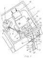
- FIG. 1 A possible spectral distribution of the signal emitted by the security feature 13 is shown schematically in FIG. In the coordinate system, the intensity A is given on the ordinate and the wavelength ⁇ on the abscissa. It is assumed that the laser excitation 34 takes place at a specific wavelength ⁇ 1 and that the authenticity feature 13 then responds with a corresponding up-conversion luminescence 35 with a lower wavelength ⁇ 2 . This up-conversion luminescence 35 is detected and evaluated by the evaluation unit 18.
- the optical head 17 is now such designed that the filters and / or mirrors and / or gratings described above only the signals of a certain wavelength range with a width of 100 nm, preferably with a width of 10 nm.
- the Evaluation unit 18 now detects the intensity of the signal over a specific one Measurement period.
- a measurement period could be, for example, the time which passes until the document sensor 19 receives a new security document detected.
- the measurement period is therefore variable.
- the period of time can also be preset and the Correspond to the time in which a security document is able to emit radiation emit. This time depends on the relative speed at which the Move security documents past the sensor in the direction of the arrow 12.
- Such a signal S1 detected by the evaluation unit 18, is shown in FIG shown schematically in a diagram. It is on the abscissa of the Time t and the intensity A on the ordinate.
- the Signal S1 rises over a certain time, then passes through several local ones Maxima and minima and then falls off again.
- the detected signal S1 is now in a first Embodiment of the invention examined in terms of which Period there is a certain, predetermined intensity threshold A1 exceeds.
- the signal is, for example, in small time units discretized.
- the evaluation unit 18 determines the period in which the Intensity threshold is exceeded, for example as the sum of the time units, in which the intensity is above or at the intensity threshold A1.
- the example shown in FIG. 4 is the length of the period, at which the intensity threshold A1 is exceeded, designated and extends with ⁇ t between the first time t1 and the second time t2.
- the Period of time ⁇ t is then specified by the evaluation unit with a predetermined one Setpoint t (setpoint) compared.
- the security document is recognized as genuine.
- the Measured time period ⁇ t with different target values t (target1), t (target2) etc. is compared. Is the amount of the difference between the determined period ⁇ t and one of the target values t (target1), t (target2) less than or equal to a predetermined value Difference value, then the security document is recognized as genuine and that Security document can be of a certain type or a certain Nominal value can be assigned.
- the banknotes different countries or the stamps with different values be distinguished.
- the ad unit can then output the result of the analysis become.
- a red lamp can light up when a Security document is recognized as fake.
- the recognized value for example a postage stamp
- the measured time-dependent Intensity profile with intensity profile patterns stored in a database compared.
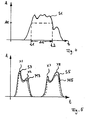
- This exemplary embodiment is intended to be based on the diagram in FIG. 5 are explained.
- the intensity A of the measured signal of a specific, predetermined wavelength range as Function of time t plotted.
- the diagram in FIG. 5 represents two successively measured signals S3 and S5 schematically.
- the first signal S3 belongs to a first security document and the second signal has been S5 measured against a second security document.
- the profiles of both signals have rising edges at the beginning and falling edges at the end.
- the first signal S3 is represented by a first maximum X1 and second maximum X2 and an intermediate minimum in intensity characterized.
- the second signal S5 points between the rising and the falling edge, a first maximum X7 and a second maximum X8 and one intermediate minimum. Both signals differ in that that the maxima and the minima in both intensity and location are different on the timescale.
- the evaluation unit now takes one Comparison of the intensity profile patterns stored in the database with the measured intensity profiles S3 and S5 over a certain period of time in front. For this purpose, the signals are discriminated, for example, and accordingly compared discriminated entries in the database. The result is that Signal S3 the least deviation from the intensity profile pattern M3 and that Signal S5 shows the smallest deviation from the intensity profile pattern M5. is the deviation (i.e.
- Evaluation unit 18 recognized that the security document with the signal S3 is genuine and a certain nominal value which is assigned to the pattern M3, corresponds, and analogously, that the security document with the signal S5 is genuine and a certain nominal value which is assigned to the pattern M5, equivalent. If the deviation is not greater than a specific, fixed one Sum threshold, then the corresponding security document as Counterfeit detected. Analogous to the previously described embodiment of the Invention can be the result of analyzing the signals in a display unit being represented.
- the following is intended to be based on of the signals S7 and S8 shown in FIG. 6 are explained.
- This corresponds to the representation of the signals of the representation chosen in Figures 4 and 5.
- the two signals shown those of different, successively measured Security documents originate from the fact that the rise of the emitted signal is different.
- This takes advantage of this evaluation method now described. Between two fixed ones The evaluation unit calculates the mean times t4 and t5 or t4 'and t5' Slope (first derivative) of the signal. The slope is in Figure 6 above the respective signal curve and drawn with G1 (signal S7) and G3 (signal S8) designated.
- the slopes G1 and G3 are included in a database stored target increase value G (target1), G (target2) etc. Is the Deviation from a certain target increase value smaller than a certain, predefined increase threshold value, it is recognized that the corresponding Security document is real. It can also be of a certain type or one certain nominal value. Corresponds to the measured Slope value not a target slope value from the database in corresponding limits, then the corresponding security document is considered Counterfeit detected.
- the corresponding deviation values can also be provided in the database in this way, that it matches the target value or the intensity profile pattern or the target increase value, which is the smallest deviation from the respective determined value owns are assigned. Then the corresponding difference with the corresponding specific difference value or total threshold value or Rise threshold compared.
- the basis of all methods for the authenticity detection of Security features on value and security documents is the knowledge that the on and / or the decay time, especially the decay time, of emitted Radiation is an essential characteristic of the security element.
- This Characteristic is very forgery-proof, because a variation of the arrival and Cooldowns of phosphors that emit radiation, for example, by the change in the doping or by the incorporation of impurities in the Crystal lattice is made that is difficult to detect and difficult for a forger are imitable.
- the signals in one certain, fixed predetermined larger wavelength range in addition to evaluating the intensity of the signal in a particular Wavelength range with a very limited size the signals in one certain, fixed predetermined larger wavelength range.
- This is the optical head 17 with the corresponding filters and / or mirrors and / or Bars equipped.
- that of the Security element emitted electromagnetic radiation depending on the wavelength in the larger wavelength range by the evaluation unit 18 recorded.
- Several emission lines are generally recorded, such as this is shown, for example, on the basis of lines 35 and 36 in FIG. 3.
- the evaluation unit determines as a measure of the intensity of the respective Line the area under the respective emission line. After that, the relationship the intensities of two selected lines and one Intensity ratio setpoint compared that is stored in the database.
- the Matching the setpoint can be used as an additional criterion for detection the authenticity or a nominal value, because the variation of the arrival and Cooldowns of the up-conversion luminescence also the Intensity ratios can be varied.
- a can be used as a measure of the intensity.
- Emission line also the intensity value at the point of the maximum of the respective Line can be used.
- the system is based on the schematic drawing shown in Figure 7 explained.
- the sensor unit 50 contains a first sensor element 53, a second one Sensor element 54, a third sensor element 55 and a stamp and Release element 57, wherein the mailpiece contains the elements of sensor unit 50 in in the order mentioned.
- the mail item is analyzed in the first sensor element 53 in such a way that whether it contains stamps or a release stamp and if so, on which one Place of the mailing.
- Known for this purpose in the sensor element 53 methods based on image recognition are used. Won this Information on whether there are stamps or release stamps and on which ones Place the stamps or the release stamps are arranged on the third sensor element 55 passed on. Are neither stamp nor The stamp will contain a release stamp on the mailpiece discarded.
- the mail item is then conveyed on to the second sensor element 54.
- This sensor element checks using image recognition methods and a weight measurement, which type of mail item is present. In doing so for example, different types of cards and letters according to their size and their Weight and different types of packages and parcels also according to their size and their weight. Also that of the second sensor element Information obtained is forwarded to the third sensor element 55.
- the third sensor element 55 now takes over after the mail item arrives this element has been forwarded, analogous to one or more of the above Exemplary embodiments described the analysis of the security elements of the Postage stamp or release stamp.
- the third sensor element has one Structure that is analogous to the sensor element shown in Figure 1.
- the at least one stamp or the release stamp is issued by the third Sensor element 55 examined for authenticity and / or value.
- a hollow mirror mentioned above in the beam path of the emitted steel is advantageous because the heights of the mail items are different do not affect the focus of the emitted beam.
- the at least one stamp and / or the release stamp are compared. is the value determined is greater than or equal to that based on the type of mail item expected value, then the mail item in the release and stamp unit 57 released and for example with a canceling postmark Mistake. If the determined value is smaller than the expected value, the The mail item is sorted out and marked, for example, in order to Initiate payment of a cash on delivery.
- the embodiment described above can also without Valuation and comparison are carried out. Then the value of the Release stamp or the at least one stamp in another way examined and with a setpoint dependent on the type of mail item be compared.
- the sensor unit 50 guides by means of the third Sensor element 53 only authenticity detection in the at least one Postage stamp or the release stamp contained security features and by. In this case, the second sensor element 54 is omitted.
- the security element in the form of pigments, which when stimulated by electromagnetic radiation of a certain wavelength radiation in one emit other wavelength range, are in a known manner in the insert or apply at least one stamp.
- the release stamp contains in its color the corresponding pigments.
Abstract
Description
Die Erfindung betrifft ein Verfahren für die Echtheitserkennung von Wertund/oder
Sicherheitsdokumenten nach dem Oberbegriff des ersten
unabhängigen Anspruchs und einen entsprechenden Sensor nach dem
Oberbegriff des zweiten unabhängigen Anspruchs.
Als Wert- und Sicherheitsdokumente werden in den nachfolgenden Ausführungen
insbesondere Postwertzeichen oder Freigabestempel, die auf Briefen, Päckchen
und sonstigen Verpackungen in den Postsortiermaschinen vereinzelt werden,
angesehen. Weiterhin werden unter derartigen Wert- und Sicherheitsdokumenten
Banknoten, Ausweise, Pässe, Verpackungen, Label und Aufkleber, Fahrausweise,
Eintrittskarten und andere Tickets, Steuerzeichen, Pfandwertzeichen sowie Aktien
verstanden. Im weiteren Sinne werden im Rahmen der nachfolgenden
Offenbarung alle bedruckbaren und sonstwie mit Sicherheitsmerkmalen
versehbaren Erzeugnisse, beispielsweise Verpackungen, als Wert- und
Sicherheitsdokumente angesehen.The invention relates to a method for the authenticity detection of value and / or security documents according to the preamble of the first independent claim and a corresponding sensor according to the preamble of the second independent claim.
In the following explanations, postage stamps or release stamps, which are isolated on letters, parcels and other packaging in the mail sorting machines, are regarded as value and security documents. Furthermore, such value and security documents are understood to mean banknotes, ID cards, passports, packaging, labels and stickers, travel cards, admission tickets and other tickets, control signs, pledged value signs and shares. In the broader sense, in the context of the following disclosure, all printable products and products which are otherwise provided with security features, for example packaging, are regarded as value and security documents.
Ein nach der DE 4117011 A1 bekannter Sensor soll diffuse, intensitätsschwache Strahlungen erfassen, wie sie bei der Prüfung von mit Lumineszenz-Merkmalen versehenen Banknoten auftreten.A sensor known from DE 4117011 A1 is said to be diffuse, weak in intensity Detect radiation as when testing with luminescent features provided banknotes occur.
Das dort beschriebene Sensorsystem besteht aus einem konisch aufgeweiteten Lichtfaserstab und einer weiterverarbeitenden Optik, wobei mit dem schmalen Querschnittsende des Faserstabes die vom Messobjekt kommende Strahlung in einem grossen Raumwinkel erfasst werden kann. Die Strahlung tritt aufgrund der Querschnittswandlung unter einem wesentlich kleinerem Winkel, der auf den Öffnungswinkel der nachfolgenden Optik abgestimmt ist, aus dem Faserstab aus.The sensor system described there consists of a flared one Optical fiber rod and a processing optics, with the narrow Cross-sectional end of the fiber rod the radiation coming from the measurement object in a large solid angle can be detected. The radiation occurs due to the Cross-sectional change at a much smaller angle that on the Opening angle of the following optics is matched from the fiber rod.
Mit einem derartigen Sensor ist es zwar möglich, relativ intensitätsschwache Lumineszenz-Merkmale zu erfassen; jedoch kann die Stärke der erfassten Lumineszenz-Merkmale keine bestimmte Schwelle unterschreiten. Er ist also noch relativ unempfindlich. Aufgrund der Verwendung eines konisch ausgebildeten Faserstabes besteht nämlich der Nachteil, dass lediglich ein punktförmiger Bereich auf dem Dokument überwacht und geprüft werden kann, was dann scheitert, wenn das zu untersuchende Element (Signet oder Sicherheitsmerkmal genannt) an anderen Stellen des Dokumentes angeordnet ist. Eine Hochgeschwindigkeitserkennung von Sicherheitsdokumenten, bspw. Postwertzeichen, wie sie in den üblichen Sortier- und Verteil- oder Zählmaschinen üblich ist, ist mit dieser Anordnung jedoch nicht möglich. Auch können bei Laseranregung keine für die Echtheitserkennung entscheidenden, charakteristischen Impulsantworten erkannt und ausgewertet werden.With such a sensor, it is possible to have relatively low intensity Capture luminescence features; however, the strength of the captured Luminescence characteristics do not fall below a certain threshold. So he's still relatively insensitive. Due to the use of a tapered The disadvantage of the fiber rod is that it is only a punctiform one Area on the document can be monitored and checked, then what fails if the element to be examined (signet or security feature called) is arranged at other points in the document. A High-speed detection of security documents, e.g. Postage stamps as they are in the usual sorting and distribution or counting machines is common, but is not possible with this arrangement. Can also at Laser excitation not decisive for authenticity detection characteristic impulse responses can be recognized and evaluated.
Das erfindungsgemäße Verfahren und der erfindungsgemäße Sensor mit den Merkmalen der unabhängigen Ansprüche haben demgegenüber den Vorteil, dass eine Echtheitserkennung von Sicherheitsdokumenten mit Geschwindigkeiten, wie sie in den bekannten Verteil- und Zählmaschinen üblich ist, erfolgen kann. Desweiteren ist eine Erkennung des Nominalwerts des Sicherheitsdokuments möglich.The inventive method and the inventive sensor with the In contrast, features of the independent claims have the advantage that authenticity detection of security documents at speeds such as it is common in the known distribution and counting machines can be done. Furthermore, there is a recognition of the nominal value of the security document possible.
Die weiteren Vorteile der Erfindung ergeben sich aus der nachfolgenden stichwortartigen Zusammenstellung und aus der Beschreibung der Ausführungsbeispiele:The further advantages of the invention result from the following keyword-like compilation and from the description of the EXAMPLES
Der erfindungsgemässe Sensor eignet sich zur Montage in einer
(Hochgeschwindigkeits-) Transportvorrichtung und kann auch als Scanner
ausgebildet sein.
Er eignet sich zur Detektion eines Sicherheitsmerkmales vorwiegend auf flachen
Objekten.
Als detektierbares Sicherheitsmerkmal wird ein Sicherheitsmerkmal bestehend
aus einer Farbe mit beigemischten Up-Conversion- Pigmenten (im folgenden auch
als Anti-Stokes-Leuchtstoffe bezeichnet) vorgeschlagen. Allenfalls können diese
Pigmente auch in einer aufgebrachten Lösung, einem aufgebrachten Lack, dem
Kleber oder einem Träger, beispielsweise Papier, direkt beigemischt werden. The sensor according to the invention is suitable for mounting in a (high-speed) transport device and can also be designed as a scanner.
It is suitable for the detection of a security feature primarily on flat objects.
A security feature consisting of a color with added up-conversion pigments (also referred to below as anti-Stokes phosphors) is proposed as a detectable security feature. At most, these pigments can also be admixed directly in an applied solution, an applied lacquer, the adhesive or a carrier, for example paper.
Der Sensor ist vorteilhaft zur Detektierung eines (z.B. aufgedruckten) Sicherheitsmerkmales mit kleinen Abmessungen (z.B. 5x5 mm) geeignet. Bei Aufbringung des Sicherheitsmerkmales durch ein Druckverfahren kann der Aufdruck in relativ weiten Grenzen aufgebracht werden. Der geforderte Sensor-Messbereich muss deshalb das gesamte, mögliche Druckfeld erfassen, obwohl das aufgedruckte Sicherheitsmerkmal irgendwo in diesem Druckbereich aufscheinen kann und das Sicherheitsmerkmal um ein Vielfaches kleiner ist als der Druckbereich.The sensor is advantageous for the detection of a (e.g. printed) Security feature with small dimensions (e.g. 5x5 mm) suitable. at The security feature can be applied by a printing process Imprint can be applied within relatively wide limits. The required sensor measuring range must therefore capture the entire possible pressure field, although the security feature printed somewhere in that printing area can appear and the security feature is many times smaller than the print area.
Der Messbereich (Scanbereich, quer zur Transportrichtung) kann beispielsweise bis zu 70 mm gross sein und eine Detektierung des kleinen Sicherheitsmerkmales erfolgt innerhalb dieses grossen Messbereiches.The measurement area (scan area, transverse to the transport direction) can, for example be up to 70 mm in size and detect the small security feature takes place within this large measuring range.
Es erfolgt bevorzugt eine ortsaufgelöste Detektierung in Transportrichtung.
Die Geschwindigkeit in Transportrichtung variiert von Null bis 12 m/s.
Bevorzugt erfolgt auch eine Ausführung als Zweibereichssensor, bei dem eine
einzige Beleuchtung das Testobjekt beleuchtet und bei dem zwei verschiedene
spektrale Bereiche ausgewertet werden.A spatially resolved detection is preferably carried out in the transport direction.
The speed in the direction of transport varies from zero to 12 m / s.
An embodiment as a two-range sensor is preferably also carried out, in which a single illumination illuminates the test object and in which two different spectral ranges are evaluated.
Als zusätzliches Merkmal kann ein integrierter oder externer Objektdetektor (optische Schranke) verwendet werden, der dem Sensor angibt, wann das Objekt (Sicherheitsmerkmal) beginnt und wann es endet.An additional feature is an integrated or external object detector (optical barrier) can be used, which indicates to the sensor when the object (Security feature) begins and when it ends.
Bei Verwendung eines Synchronisationseinganges, der mit einem geschwindigkeitsproportionalen Schaltsignal gespeist wird, kann auch bei Geschwindigkeitsvariationen ein gewisser, vorgegebener Teilausschnitt des Testobjektes allein untersucht werden.When using a synchronization input with a speed-proportional switching signal can also be fed Speed variations a certain, predetermined section of the Test object to be examined alone.
Vorteilhaft werden Pigmente mit einer schnellen Anstiegs- und einer schnellen Abfallszeit (z.B. typisch 0,01 - 1 ms) verwendet, um eine Detektion bei den gewünschten hohen Geschwindigkeiten zu erlauben. Es erfolgt natürlich eine Anpassung der elektronischen Auswertung an die charakteristischen Zeiten der Pigmente. Pigments with a rapid increase and a rapid increase are advantageous Fall time (e.g. typically 0.01 - 1 ms) used to detect the to allow desired high speeds. Of course there is one Adaptation of the electronic evaluation to the characteristic times of the Pigments.
Es wird beispielsweise eine Laserwellenlänge oberhalb von 900 nm verwendet. Andere Laserwellenlängen sind ebenfalls möglich. Außerdem kann die spektrale Breite der Laserlinie variieren. Es können aber auch LED's oder andere Lichtquellen verwendet werden. Es werden mehrere parallele Strahlen verwendet, die relativ dicht beieinander liegen, um die kleinen markierten Sicherheitsmerkmale zu erkennen. Desweiteren ist die Verwendung einer breitbandigen Quelle elektromagnetischer Strahlung möglich.For example, a laser wavelength above 900 nm is used. Other laser wavelengths are also possible. In addition, the spectral The width of the laser line vary. However, LEDs or others can also be used Light sources are used. Multiple parallel beams are used which are relatively close together around the small marked ones Recognize security features. Furthermore, the use of a broadband source of electromagnetic radiation possible.
Die erfindungsgemässe Laserlinie (erzeugt mit normalen Zylinderlinsen) erzeugt eine Bestrahlungsstärke, die am höchsten in der Mitte der Linie ausgebildet ist. Die Laserlinie wird bevorzugt mit einer asphärischen Zylinderlinse erzeugt oder alternativ mit einem Zylinderlinsenarray oder in einer anderen Alternative mit einer sinus-wellenförmigen Linsenoberfläche; die Bestrahlungsstärke ist hier entweder homogen über die ganze Länge der Laserlinie verteilt oder leicht überhöht am Rand (oder ebenfalls in der Mitte), um die Empfindlichkeitsvariation des Empfängers über den Messbereich zu kompensieren.The laser line according to the invention (produced with normal cylindrical lenses) is produced an irradiance that is highest at the center of the line. The laser line is preferably generated with an aspherical cylindrical lens or alternatively with a cylindrical lens array or in another alternative with a sinusoidal wavy lens surface; the irradiance is either here homogeneously distributed over the entire length of the laser line or slightly elevated on Edge (or also in the middle) to the sensitivity variation of the To compensate the receiver over the measuring range.
Die Fokussierung in der Objektebene wird so ausgebildet, dass allenfalls bei Verwendung ohne Laserlinie eine leichte Defokussierung vorliegt, um für die Pigmente eine optimale Bestrahlungsstärke zu erreichen. Die Lumineszenzeffizienz variiert mit der Bestrahlungsstärke und hat meist ein Optimum bei hoher, jedoch nicht allzu hoher Bestrahlungsstärke. Bei zu hoher Bestrahlungsstärke fällt die Signalstärke des empfangenen Lichtes wieder ab.The focus in the object plane is designed so that at most Use without a laser line is a slight defocus in order for the Pigments to achieve optimal irradiance. The Luminescence efficiency varies with the irradiance and usually has one Optimal at high, but not too high irradiance. If it is too high Irradiance drops the signal strength of the received light again.
Mit Vorteil wird ein stark divergierender Laserstrahl eingesetzt, um aus Kostengründen in eine niedrige Laserklasse bei der Herstellung des Sensors zu gelangen.A highly divergent laser beam is advantageously used to get out Cost reasons in a low laser class in the manufacture of the sensor reach.
Es findet eine optische Filterung der unerwünschten Wellenlängen der Lichtquelle im spektralen Detektionsbereich statt. Eine Unterdrückung wird auf < 10-7 bevorzugt, wobei das Sicherheitsmerkmal mindestens während zweier Perioden erkannt werden muss. Ansonsten wird es als ungenügend verworfen. The undesired wavelengths of the light source are optically filtered in the spectral detection range. Suppression is preferred to <10 -7 , the security feature having to be recognized for at least two periods. Otherwise it is rejected as insufficient.
Zur Verwirklichung der synchronen Verstärkung erfolgt die Auswertung über eine Analogschaltung mit Sample & Hold Gliedern. Die synchrone Verstärkung wertet nur Lichtsignale aus, die in Phase mit der Repetitionsfrequenz des ausgesandten Laserlichtes empfangen wird. Darüber hinaus kann die Signalauswertung weitere Details enthalten, wie z.B. Sampling des Signals nach in der Anstiegsflanke zu einem ersten Zeitpunkt nach Pulsbeginn und Vergleich dieses Signals mit dem Signal zu einem zweiten Zeitpunkt nach Pulsbeginn. Dazu müssen die gewählten Zeitfenster an die Bandpassfrequenz der Elektronik und insbesondere an die Anstiegs- und Abfallszeiten der Pigmente angepasst werden. Die Kontrolle über diese Signale und Zeitsignale erfolgt vorteilhafterweise durch einen Mikroprozessor. Dasselbe Prinzip kann in der Pulspause erfolgen und das Abklingverhalten des Signals untersuchen.To achieve synchronous amplification, the evaluation is carried out using a Analog circuit with sample & hold elements. The synchronous amplification evaluates only light signals emitted in phase with the repetition frequency of the Laser light is received. In addition, the signal evaluation can be further Include details such as Sampling of the signal after on the rising edge a first point in time after the start of the pulse and comparison of this signal with the Signal at a second time after the start of the pulse. To do this, the elected Time window to the bandpass frequency of the electronics and in particular to the Rise and fall times of the pigments can be adjusted. Control over these signals and time signals are advantageously carried out by a Microprocessor. The same principle can be done during the pulse pause and that Examine the decay behavior of the signal.
Alternativ kann die Auswertung unter Einsatz eines Mikroprozessors mit integriertem oder externem A/D-Wandler erfolgen. Das gleiche Auswerteprinzip kann dabei angewendet werden.Alternatively, the evaluation can be carried out using a microprocessor integrated or external A / D converter. The same evaluation principle can be applied.
Durch die Einbeziehung der Zeitabhängigkeit des Intensitätssignals bei einer bestimmten Wellenlänge in die Analyse wird eine zusätzliche Ebene der Sicherheit geschaffen. Da die Zeitabhängigkeit des Signals sehr stark vom Anund Abklingverhalten, insbesondere vom Anklingverhalten, des emittierten Signals abhängig ist und dieses wiederum beispielsweise sehr leicht durch die Dotierung von Yb und Tm im Leuchtstoff variierbar ist, bietet das erfindungsgemäße Verfahren bzw. der erfindungsgemäße Sensor eine sehr fälschungssichere Verschlüsselungsmöglichkeit des Nominalwerts des Sicherheitsdokuments oder der Art des Sicherheitsdokuments.By including the time dependence of the intensity signal at a certain wavelength in the analysis will add an additional level of Security created. Since the time dependence of the signal is very dependent on the on and off Decay behavior, in particular of the response behavior, of the emitted Signal is dependent and this in turn, for example, very easily through the Doping of Yb and Tm in the phosphor can be varied, that offers the method according to the invention or the sensor according to the invention is a very Forgery-proof encryption option for the nominal value of the Security document or the type of security document.
Mit dem erfindungsgemäßen Sensor bzw. mit dem erfindungsgemäßen Verfahren
werden Sicherheitsmerkmale eines Sicherheitsdokuments detektiert, wobei das
Sicherheitsmerkmal beispielsweise einen Anti-Stokes-Leuchtstoff (Synonyme:
Anti-Stokes-Pigment, Anti-Stokes-Phosphor, Up-Conversion-Material) verwendet.
Dabei handelt es sich um ein Thulium-aktiviertes und Ytterbium-kodotiertes
Gadoliniumoxysulfid der Zusammensetzung
Alternativ können auch andere Pigmente eingesetzt werden, wobei das An- und Abklingverhalten, insbesondere das Anklingverhalten der emittierten Strahlung des Pigments eine schnelle Detektion der emittierten Strahlung erlauben muss. Dies können beispielsweise Photo-, Kathodo- oder Elektroluminophoren sein.Alternatively, other pigments can also be used, with the addition and Decay behavior, in particular the response behavior of the emitted radiation of the pigment must allow rapid detection of the emitted radiation. These can be, for example, photo, cathodophores or electroluminophores.
Bei dem hier dargestellten Sensor bzw. Detektionsverfahren entscheidet die Anund Abklingcharakteristik des verwendeten Anti-Stokes-Leuchtstoffes und insbesondere die Abstimmung der Anregungs- und Auswerteeinheit auf die Anund Abklingcharakteristik des entsprechenden Leuchtstoffs in hohem Maße über die erreichbare Detektionssicherheit und die mögliche Auslesegeschwindigkeit eines maschinell zu prüfenden Lumineszenzmerkmals. Dabei kann das Anklingen z.B. durch die Zeitdauer, die für das Erreichen des 90 %Wertes (t90) der Sättigungsintensität benötigt wird oder aber durch die sogenannte Anklingkonstante (Zeitdauer für das Erreichen von 1/e-tel der stationären Lumineszenzintensität) gekennzeichnet werden.In the sensor or detection method shown here, the response and decay characteristics of the anti-Stokes phosphor used and in particular the coordination of the excitation and evaluation unit to the response and decay characteristics of the corresponding phosphor largely determine the achievable detection reliability and the possible readout speed of a machine test Lumineszenzmerkmals. The response can be characterized, for example, by the time required to reach the 90% value (t 90 ) of the saturation intensity or by the so-called response constant (time required to reach 1 / eth of the stationary luminescence intensity).
Bei gegebener hoher Auslesegeschwindigkeit darf die Anklingzeit der Anti-Stokes-Lumineszenz einen bestimmten Wert nicht überschreiten, wenn eine über der Empfindlichkeitsschwelle des Detektors liegende effektive Lumineszenzintensität gesichert werden soll. Dieser Effektivwert der Intensität wird durch die Relation zwischen der stationären Intensität und die Anklingzeit bestimmt.Given the high readout speed, the response time of the anti-Stokes luminescence is allowed not exceed a certain value if one is above the Sensitivity threshold of the detector lies effective luminescence intensity should be secured. This effective value of the intensity is determined by the relation determined between the stationary intensity and the response time.
Desweiteren zeigen die vom Leuchtstoff emittierten Signale aufgrund ihres bestimmten An- und Abklingverhaltens ein charakteristisches Intensitätsprofil in Abhängigkeit von der Zeit. Gegenstand der hier dargestellten Erfindung ist die Erkenntnis, dass Anti-Stokes- und andere Lumineszenzintensitäten nicht nur in Bezug auf ihre spektrale Verteilung, sondern zusätzlich in Bezug auf ihre zeitliche Abhängigkeit zur Analyse von Echtheits- und Nominalwerterkennung genutzt werden können.Furthermore, the signals emitted by the phosphor show due to their a certain intensity profile in certain response and decay behavior Dependence on time. The subject of the invention shown here is Realization that anti-Stokes and other luminescence intensities are not only in In terms of their spectral distribution, but also in terms of their temporal Dependency used to analyze authenticity and nominal value recognition can be.
Im Falle des Leuchtstoffs (Gd1-x-yYbxTmx)2O2S lassen sich die Verhältnisse zwischen der Sättigungsintensität und den An- und Abklingzeiten in einem weiten Bereich variieren. Insbesondere gelingt es, die für die Realisierung einer High-Speed-Detektion erforderlichen niedrigen Anklingzeiten sicher zu stellen. Zu diesem Zwecke werden die Ytterbium- und/oder Thuliumkonzentrationen in bestimmten Grenzen variiert. Weitere Möglichkeiten der Beeinflussung der Anund Abklingcharakteristik liegen im gezielten Einbau von Störstellen in das Kationen- oder Anionenteilgitter des Leuchtstoffes.In the case of the phosphor (Gd 1-xy Yb x Tm x ) 2 O 2 S, the relationships between the saturation intensity and the rise and fall times can be varied within a wide range. In particular, it is possible to ensure the low response times required for the implementation of high-speed detection. For this purpose, the ytterbium and / or thulium concentrations are varied within certain limits. Further possibilities for influencing the decay and decay characteristics lie in the targeted installation of impurities in the cation or anion partial lattice of the phosphor.
Der Erfindungsgegenstand der vorliegenden Erfindung ergibt sich nicht nur aus dem Gegenstand der einzelnen Patentansprüche, sondern auch aus der Kombination der einzelnen Patentansprüche untereinander.The subject matter of the present invention does not only result from the subject of the individual claims, but also from the Combination of the individual claims.
Alle in den Unterlagen, einschließlich der Zusammenfassung, offenbarten Angaben und Merkmale, insbesondere die in den Zeichnungen dargestellte räumliche Ausbildung werden als erfindungswesentlich beansprucht, soweit sie einzeln oder in Kombination gegenüber dem Stand der Technik neu sind.All disclosed in the file, including the summary Information and features, especially those shown in the drawings spatial education are claimed as essential to the invention, insofar as they individually or in combination are new compared to the prior art.
Im folgenden werden Ausführungsbeispiele der Erfindung anhand von Zeichnungen näher erläutert. Hierbei gehen aus den Zeichnungen und ihrer Beschreibung weitere erfindungswesentliche Merkmale und Vorteile der Erfindung hervor.In the following, exemplary embodiments of the invention are described with reference to Drawings explained in more detail. Here go from the drawings and their Description of further features and advantages of the invention essential to the invention out.
Es zeigen:
- Figur 1:
- Eine Draufsicht des Messsensors nach der Erfindung, schematisch,
- Figur 2:
- Eine Darstellung des von der Strahlungsquelle ausgesandten Strahlbündels, schematisch,
- Figur 3:
- Eine Emissionsantwort des Leuchtstoffes im Spektraldiagramm, schematisch,
-
Figuren - Darstellungen der Zeitabhängigkeit des aufgenommenen Signals, schematisch, und
- Figur 7:
- Eine Darstellung eines weiteren Ausführungsbeispiels des Sensors, schematisch.
- Figure 1:
- A plan view of the measuring sensor according to the invention, schematically,
- Figure 2:
- A representation of the beam emitted by the radiation source, schematically,
- Figure 3:
- An emission response of the phosphor in the spectral diagram, schematically,
- Figures 4, 5 and 6:
- Representations of the time dependence of the recorded signal, schematically, and
- Figure 7:
- A representation of a further embodiment of the sensor, schematically.
Der Einfachheit halber wird in der folgenden Beschreibung davon ausgegangen, dass als Strahllichtquelle ein Laser verwendet wird. Hierauf ist die Erfindung jedoch nicht beschränkt, statt eines Lasers kann als Strahllichtquelle auch ein oder mehrere LED's verwendet werden oder die anderen, im allgemeinen Teil erwähnten Lichtquellen.For the sake of simplicity, the following description assumes that a laser is used as the beam light source. This is the invention but not limited, instead of a laser, one can also be used as the beam light source or more LEDs are used or the others, in the general part mentioned light sources.
Im Fall der Verwendung eines Lasers wird die im allgemeinen Beschreibungsteil erwähnte Laserwellenlänge bevorzugt.In the case of using a laser, the general description section mentioned laser wavelength preferred.
Die Verwendung eines Lasers hat im übrigen den Vorteil, dass die Abtastlinie mit relativ hoher Strahlungsintensität auf der Oberfläche des Dokumentes abgebildet wird, was bei der Verwendung von anderen Strahlquellen in nicht so hohem Masse geschieht.The use of a laser also has the advantage that the scanning line with relatively high radiation intensity mapped on the surface of the document becomes what is not so high when using other beam sources Mass happens.
Die Leuchtdichte ist bei Verwendung von anderen Strahlquellen, insbesondere von LED's dann entsprechend niedriger. Für manche Anwendungszwecke kann dies aber ausreichen.The luminance is particularly good when using other beam sources of LEDs then correspondingly lower. Can be used for some applications but this is sufficient.
In Figur 1 ist allgemein in einem Gehäuse 1 ein Laser 2 in einem eigenen
Gehäuse untergebracht, wobei in nicht näher dargestellter Weise im Innenraum
des Gehäuses eine Fokussierlinse 4 angeordnet ist (siehe auch Figur 2) und vor
der Strahlöffnung 3 eine Zylinderlinse 5, welche das Strahlbündel 6 entsprechend
aufweitet, so dass es in der eingezeichneten Pfeilrichtung auf das Messfenster 10
unter Bildung einer etwa strichförmige Abtastlinie 9 gestrahlt wird. In Figure 1 there is generally a
Das Messfenster 10 sei hierbei durch eine Glasscheibe abgeschlossen. Dicht vor
dem Messfenster und praktisch berührend auf der Glasscheibe läuft das zu
untersuchende Sicherheitsdokument 11 in Pfeilrichtung 12 vorbei, wobei auf dem
Sicherheitsdokument ein Echtheitsmerkmal 13 in einem bestimmten Bereich
angeordnet ist. Das Echtheitsmerkmal 13 kann an verschiedenen Stellen, zum
Beispiel auch an den Stellen 13' oder 13" angeordnet sein. Die Länge der
Abtastlinie 9 wird dabei in vorteilhafter Weise mindestens in der Größe gewählt,
die äusserstenfalls der Breite des Sicherheitsdokuments entspricht, so dass durch
die Länge der Abtastlinie 9 stets dafür gesorgt ist, dass diese auch ein
Echtheitsmerkmal 13 trifft, auch wenn dies an unerwarteter Stelle auf dem
Sicherheitsdokument 11 angeordnet ist.The
Der Vollständigkeit halber sei noch erwähnt, dass das Strahlbündel 6 durch ein
Fenster 8 im Bereich einer mehrerer Fenster aufweisende Blende 7 hindurchgeht.For the sake of completeness, it should also be mentioned that the
Das Sicherheitsmerkmal 13 arbeitet nach dem oben beschriebenen Effekt und
strahlt nach der Anregung durch das Laserlicht entlang der Abtastlinie 9 in den
eingezeichneten Pfeilrichtungen einen emittierten Strahl 14 durch das
Messfenster 10 wieder hindurch und passiert in Pfeilrichtung 15 das Fenster 16.The
Dieser Strahl in Pfeilrichtung 15 wird dann in einem Optikkopf 17 weiterverarbeitet
und schliesslich einer Auswerteeinheit 18 zugeführt. Diese Auswerteeinheit
besteht bevorzugt aus einem Photomultiplier (Sekundärelektronenvervielfacher).This beam in the direction of
Statt eines Photomultipliers können auch andere Auswerteeinheiten verwendet werden, wie zum Beispiel Photodioden, eine Matrix-Kamera, die mit einem CCD-Chip oder einem CMOS-Chip arbeitet.Instead of a photomultiplier, other evaluation units can also be used such as photodiodes, a matrix camera with a CCD chip or a CMOS chip works.
In der Darstellung der Figur 1 ist der besseren Übersichtlichkeit halber dargestellt,
dass das Dokument 11 einen bestimmten Abstand vom Messfenster 10 aufweist.
Dies ist tatsächlich nicht der Fall, denn das Dokument 11 soll möglichst dicht,
wenn nicht sogar berührend, an dem Messfenster 10 in Pfeilrichtung 12 vorbei
bewegt werden. For the sake of clarity, the illustration in FIG. 1 shows
that the
Optional kann in dem Gehäuse 1 noch ein sogenannter Dokumentensensor 19
vorhanden sein, der bevorzugt als Lichtschranke ausgebildet ist. Es wird hierbei
ein Messstrahl 21 auf das zu untersuchende Dokument geleitet und von diesem
Dokument in Pfeilrichtung 22 als Reflektionsstrahl reflektiert und durch das
Fenster 20 zurückgeworfen. In einem weiteren Ausführungsbeispiel kann die
Anregung durch den Messstrahl 21 auch eine Emission von Strahlung in die
Pfeilrichtung 22 hervorrufen, die dann durch das Messfenster 22 dringt. Hiermit
wird festgestellt, ob überhaupt ein Dokument anwesend ist oder nicht. Danach
wird erst die Laseroptik freigeschaltet, welche die vorgenannte Abtastlinie 9 auf
der zu untersuchenden Dokumentenoberfläche 11 erzeugt. In diesem Fall
geschieht die Auswertung des Echtheitsmerkmals in vorteilhafter Weise nur in der
Zeit, in der der Dokumentensensor 19 das Vorhandensein eines Dokumentes
überhaupt festgestellt hat.Optionally, a so-called
In Figur 2 ist der Aufbau des von dem Laser 2 erzeugten Strahlbündels 6 noch
näher dargestellt. Hierbei ist erkennbar, dass vom Laser 2 zunächst der Strahl
durch eine Fokussierlinse 4 hindurch geht und erst dann von einer
nachgeschalteten Zylinderlinse 5 strichförmig aufgeweitet wird und dann durch
eine oder mehrere hintereinanderliegende Blenden 8,8' derart begrenzt wird, dass
er im Bereich des Messfensters 10 auf ein dahinterliegendes Dokument 11 die
vorher erwähnte strichförmige Abtastlinie 9 erzeugt.In Figure 2, the structure of the
Wird ein Laser 2 verwendet, hat die Abtastlinie beispielsweise eine Breite von
etwa 1 bis 3 Zehntel mm bei einer Länge von 70 mm. Die verwendete
Wellenlänge des Lasers kann beispielsweise im infraroten, sichtbaren oder
ultravioletten Wellenlängenbereich.If a
Der Optikkopf 17 beinhaltet weiterhin mindestens einen nicht dargestellten Filter,
der den durch die Auswerteeinheit 18 ausgewerteten Wellenlängenbereich
beschränkt. Beispielsweise ist mindestens ein Filter vorgesehen, der die
durchzulassende Wellenlänge selektiert. Derartige Wellenlängen können sowohl
im infraroten, als auch im sichtbaren oder ultravioletten Wellenlängenbereich
liegen und sind abhängig von der von dem Echtheitsmerkmal 13 emittierten
Strahlung. In einem weiteren Ausführungsbeispiel kann ein zusätzlicher Filter
vorgesehen sein, der das sichtbare Licht absorbiert, um es nicht auf die
Auswerteeinheit fallen zu lassen. In einem weiteren Ausführungsbeispiel können
zusätzlich zu und/oder anstatt der Filter Spiegel und/oder Gitter im Optikkopf 17
vorgesehen sein, wobei die im Strahlengang befindlichen Spiegel und/oder Gitter
einen bestimmten Wellenlängenbereich selektieren.The
Der Optikkopf 17 kann zum Ausgleich verschiedener Dicken der
Sicherheitsdokumente vorzugsweise einen nicht dargestellten Hohlspiegel
enthalten, der die vom Sicherheitsmerkmal 13 emittierte Strahlung bündelt und
diese Bündelung unabhängig von der Höhe des zu untersuchenden
Sicherheitsdokuments realisiert.The
Desweiteren kann der Optikkopf 17 einen nicht dargestellten Reflexionskonus
beinhalten, auf den das gesamte Strahlbündel gebündelt wird. Dieser
Reflexionskonus ist ein metallisch beschichteter Hohlkörper, der in Art eines
Trichters sich verengt, der innen reflektierende Oberflächen trägt. Dies sorgt
dafür, dass nicht nur die Strahlen den Reflexionskonus passieren, die unmittelbar
auf das Empfangselement abgebildet werden, sondern auch jene Strahlen auf das
Empfangselement abgebildet werden, die auf die Innenflächen des
Reflexionskonus treffen, dort reflektiert werden und sich mit dem Hauptstrahl
vereinigen. Der Reflexionskonus verstärkt also den empfangenen Lichtstrahl
wesentlich, weil nicht nur die direkten Strahlen, sondern schräg auf die
Innenwände des Reflexionskonus auftreffenden seitlichen Strahlen mit zur
Auswertung herangezogen werden.Furthermore, the
Es wurde bereits schon vorstehend erwähnt, dass für die Auswerteeinheit 18
unterschiedliche Elemente verwendet werden können; in der folgenden
Beschreibung wird von einem Photomultiplier ausgegangen. Es handelt sich
hierbei um ein etwa eine 8 mm aktive Zone umfassendes Element, welches direkt
in Körperkontakt auf der Austrittsfläche des Reflexionskonus angeordnet ist und
mit seinen Abmessungen etwa den Abmessungen der Austrittsfläche entspricht. It has already been mentioned above that for the
In Figur 3 wird allgemein eine mögliche spektrale Verteilung des vom
Sicherheitsmerkmal 13 emittierten Signals schematisch dargestellt. Hierbei ist im
Koordinatensystem auf der Ordinate die Intensität A und auf der Abszisse die
Wellenlänge λ angegeben. Es sei angenommen, dass die Laseranregung 34 bei
einer bestimmten Wellenlänge λ1 erfolgt und dass dann das Echtheitsmerkmal 13
mit einer entsprechenden Up-Conversion-Lumineszenz 35 mit einer niedrigeren
Wellenlänge λ2 antwortet. Diese Up-Conversion-Lumineszenz 35 wird von der
Auswerteeinheit 18 erfasst und ausgewertet.A possible spectral distribution of the signal emitted by the
Neben einer einzigen Up-Conversion-Lumineszenz im Wellenlängenbereich λ2 ist
es durchaus möglich, dass noch weitere Up-Conversion Lumineszenzen
beispielsweise mit der Wellenlänge λ3 bei Ziffer 36 entstehen. Auch diese können
gegebenenfalls von der Auswerteeinheit 18 erfasst werden.In addition to a single up-conversion luminescence in the wavelength range λ 2 , it is quite possible that further up-conversion luminescence, for example with the wavelength λ 3, occurs at
In einem Ausführungsbeispiel der Erfindung ist der Optikkopf 17 nun derart
gestaltet, dass die oben beschriebenen Filter und/oder Spiegel und/oder Gitter nur
die Signale eines bestimmten Wellenlängenbereichs mit einer Breite von
beispielsweite 100 nm, vorzugsweise mit einer Breite von 10 nm durchlassen. Die
Auswerteeinheit 18 erfasst nun die Intensität des Signals über einen bestimmten
Mess-Zeitraum. Ein derartiger Mess-Zeitraum könnte beispielsweise die Zeit sein,
die vergeht, bis der Dokumentensensor 19 ein neues Sicherheitsdokument
detektiert. Der Mess-Zeitraum ist somit variabel. In einem anderen
Ausführungsbeispiel kann der Zeitraum auch konstant voreingestellt sein und der
Zeit entsprechen, in der ein Sicherheitsdokument in der Lage ist, Strahlung zu
emittieren. Diese Zeit hängt von der Relativgeschwindigkeit ab, mit der sich die
Sicherheitsdokumente entlang der Pfeilrichtung 12 am Sensor vorbeibewegen.In one embodiment of the invention, the
Ein derartiges, von der Auswerteeinheit 18 erfasstes Signal S1 ist in Figur 4 in
einem Diagramm schematisch dargestellt. Dabei ist auf der Abszisse des
Diagramms die Zeit t und auf der Ordinate die Intensität A aufgetragen. Das
Signal S1 steigt über eine bestimmte Zeit an, durchläuft danach mehrere lokale
Maxima und Minima und fällt danach wieder ab. Such a signal S1, detected by the
In einem nächsten Schritt wird nun das erfasste Signal S1 in einem ersten
Ausführungsbeispiel der Erfindung dahingehend untersucht, über welchen
Zeitraum es eine bestimmte, fest vorgegebene Intensitätsschwelle A1
überschreitet. Dazu wird das Signal beispielsweise in kleine Zeiteinheiten
diskretisiert. Die Auswerteeinheit 18 ermittelt dann den Zeitraum, in dem die
Intensitätsschwelle überschritten ist, beispielsweise als Summe der Zeiteinheiten,
in denen die Intensität oberhalb oder bei der Intensitätsschwelle A1 liegt. In dem
hier anhand von Figur 4 dargestellten Beispiel ist die Länge des Zeitraums, bei
dem die Intensitätsschwelle A1 überschritten ist, mit Δt bezeichnet und erstreckt
sich zwischen dem ersten Zeitpunkt t1 und dem zweiten Zeitpunkt t2. Der
Zeitraum Δt wird anschließend von der Auswerteeinheit mit einem vorgegebenen
Sollwert t(soll) verglichen. Ist der ermittelte Zeitraum Δt größer oder gleich dem
Sollwert t(soll), dann wird das Sicherheitsdokument als echt erkannt. In einem
weiteren Ausführungsbeispiel kann auch vorgesehen werden, dass der
gemessene Zeitraum Δt mit verschiedenen Sollwerten t(soll1), t(soll2) usw.
verglichen wird. Ist der Betrag der Differenz zwischen ermitteltem Zeitraum Δt und
einem der Sollwerte t(soll1), t(soll2) kleiner oder gleich einem vorgegebenen
Differenzwert, dann wird das Sicherheitsdokument als echt erkannt und das
Sicherheitsdokument kann einer bestimmten Art oder einem bestimmten
Nominalwert zugeordnet werden. Beispielsweise können so die Banknoten
verschiedener Länder oder die Briefmarken mit verschiedenen Werten
unterschieden werden. Dabei werden in einer in der Auswerteeinheit 18
gespeicherten Datenbank oder in einer mit der Auswerteeinheit 18 verbundenen
Datenbank die Sollwerte t(soll1), t(soll2) usw. abgelegt, wobei jeder Sollwert einer
bestimmten Banknotenart oder einem bestimmten Briefmarkenwert zugeordnet
ist.In a next step, the detected signal S1 is now in a first
Embodiment of the invention examined in terms of which
Period there is a certain, predetermined intensity threshold A1
exceeds. For this purpose, the signal is, for example, in small time units
discretized. The
In einer nicht dargestellten, mit der Auswerteeinheit 18 verbundenen
Anzeigeneinheit kann anschließend das Ergebnis der Analyse ausgegeben
werden. Beispielsweise kann eine rote Lampe dann leuchten, wenn ein
Sicherheitsdokument als unecht erkannt wird. In einem anderen
Ausführungsbeispiel kann der erkannte Wert (beispielsweise einer Briefmarke) auf
einem LCD-Display angezeigt werden. In a not shown, connected to the
In einem weiteren Ausführungsbeispiel wird das gemessene zeitabhängige
Intensitätsprofil mit in einer Datenbank gespeicherten Intensitätsprofil-Mustern
verglichen. Dieses Ausführungsbeispiel soll anhand des Diagramms in Figur 5
erläutert werden. In diesem Diagramm sind analog zu Figur 4 die Intensität A des
gemessenen Signals eines bestimmten, vorgegebenen Wellenlängenbereichs als
Funktion der Zeit t aufgetragen. Das Diagramm in Figur 5 stellt dabei zwei
nacheinander gemessene Signale S3 und S5 schematisch dar. Das erste Signal
S3 gehört zu einem ersten Sicherheitsdokument und das zweite Signal S5 wurde
bei einem zweiten Sicherheitsdokument gemessen. Die Profile beider Signale
weisen am Anfang ansteigende Flanken und am Ende abfallende Flanken auf.
Dazwischen wird das erste Signal S3 durch ein erstes Maximum X1 und ein
zweites Maximum X2 und ein dazwischenliegendes Minimum in der Intensität
gekennzeichnet. Das zweite Signal S5 weist zwischen der ansteigenden und der
abfallenden Flanke ein erstes Maximum X7 und ein zweites Maximum X8 und ein
dazwischenliegendes Minimum auf. Beide Signale unterscheiden sich dadurch,
dass die Maxima und die Minima sowohl in der Intensität als auch in ihrer Lage
auf der Zeitskala unterschiedlich sind. Die Auswerteeinheit nimmt nun einen
Vergleich von den in der Datenbank gespeicherten Intensitätsprofil-Mustern mit
den gemessenen Intensitätsprofilen S3 und S5 über einen bestimmten Zeitraum
vor. Dazu werden die Signale beispielsweise diskriminiert und mit entsprechend
diskriminierten Eintragungen in der Datenbank verglichen. Im Ergebnis weist das
Signal S3 die geringste Abweichung zu dem Intensitätsprofil-Muster M3 und das
Signal S5 die geringste Abweichung zu dem Intensitätsprofil-Muster M5 auf. Ist
die Abweichung (d.h. der Betrag der Differenz zwischen dem Signal und dem
Intensitätsprofil-Muster mit der geringsten Abweichung) jeweils geringer als oder
gleich einem, bestimmter, fest vorgegebener Summenschwellwert, wird durch die
Auswerteeinheit 18 erkannt, dass das Sicherheitsdokument mit dem Signal S3
echt ist und einem bestimmten Nominalwert, der dem Muster M3 zugeordnet ist,
entspricht, und analog, dass das Sicherheitsdokument mit dem Signal S5 echt ist
und einem bestimmten Nominalwert, der dem Muster M5 zugeordnet ist,
entspricht. Ist die Abweichung nicht größer als ein bestimmter, fest vorgegebener
Summenschwellwert, dann wird das entsprechende Sicherheitsdokument als
Fälschung erkannt. Analog zu dem vorher beschriebenen Ausführungsbeispiel der
Erfindung kann das Ergebnis der Analyse der Signale in einer Anzeigeneinheit
dargestellt werden.In a further exemplary embodiment, the measured time-dependent
Intensity profile with intensity profile patterns stored in a database
compared. This exemplary embodiment is intended to be based on the diagram in FIG. 5
are explained. In this diagram, the intensity A of the
measured signal of a specific, predetermined wavelength range as
Function of time t plotted. The diagram in FIG. 5 represents two
successively measured signals S3 and S5 schematically. The first signal
S3 belongs to a first security document and the second signal has been S5
measured against a second security document. The profiles of both signals
have rising edges at the beginning and falling edges at the end.
In between, the first signal S3 is represented by a first maximum X1 and
second maximum X2 and an intermediate minimum in intensity
characterized. The second signal S5 points between the rising and the
falling edge, a first maximum X7 and a second maximum X8 and one
intermediate minimum. Both signals differ in that
that the maxima and the minima in both intensity and location
are different on the timescale. The evaluation unit now takes one
Comparison of the intensity profile patterns stored in the database with
the measured intensity profiles S3 and S5 over a certain period of time
in front. For this purpose, the signals are discriminated, for example, and accordingly
compared discriminated entries in the database. The result is that
Signal S3 the least deviation from the intensity profile pattern M3 and that
Signal S5 shows the smallest deviation from the intensity profile pattern M5. is
the deviation (i.e. the amount of the difference between the signal and the
Intensity profile pattern with the smallest deviation) each less than or
is equal to a certain, predetermined, predefined sum threshold
In einem weiteren Ausführungsbeispiel der Erfindung soll im Folgenden anhand der in Figur 6 dargestellten Signale S7 und S8 erläutert werden. Dabei entspricht die Darstellung der Signale der in den Figuren 4 und 5 gewählten Darstellung. Die beiden dargestellten Signale, die von verschiedenen, nacheinander vermessenen Sicherheitsdokumenten stammen, zeichnen sich insbesondere dadurch aus, dass der Anstieg des emittierten Signals unterschiedlich ist. Diesen Umstand nutzt das nun beschriebene Auswertungsverfahren. Zwischen zwei fest vorgegebenen Zeitpunkten t4 und t5 bzw. t4' und t5' berechnet die Auswerteeinheit die mittlere Steigung (erste Ableitung) des Signals. Die Steigung ist in Figur 6 oberhalb der jeweiligen Signalkurve eingezeichnet und mit G1 (Signal S7) und G3 (Signal S8) bezeichnet. Die Steigungen G1 bzw. G3 werden mit in einer Datenbank gespeicherten Soll-Anstiegswert G(soll1), G(soll2) usw. verglichen. Ist die Abweichung zu einem bestimmten Soll-Anstiegswert kleiner als ein bestimmter, fest vorgegebener Anstiegs-Schwellwert, wird erkannt, dass das entsprechende Sicherheitsdokument echt ist. Es kann so auch einer bestimmten Art oder einem bestimmten Nominalwert zugeordnet werden. Entspricht der gemessene Steigungswert nicht einem Soll-Anstiegswert aus der Datenbank in entsprechenden Grenzen, dann wird das entsprechende Sicherheitsdokument als Fälschung erkannt. Auch diese Analyseergebnisse können analog zu den oben beschriebenen Ausführungsbeispielen wieder in einer Anzeigeneinheit dargestellt werden.In a further exemplary embodiment of the invention, the following is intended to be based on of the signals S7 and S8 shown in FIG. 6 are explained. This corresponds to the representation of the signals of the representation chosen in Figures 4 and 5. The two signals shown, those of different, successively measured Security documents originate from the fact that the rise of the emitted signal is different. This takes advantage of this evaluation method now described. Between two fixed ones The evaluation unit calculates the mean times t4 and t5 or t4 'and t5' Slope (first derivative) of the signal. The slope is in Figure 6 above the respective signal curve and drawn with G1 (signal S7) and G3 (signal S8) designated. The slopes G1 and G3 are included in a database stored target increase value G (target1), G (target2) etc. Is the Deviation from a certain target increase value smaller than a certain, predefined increase threshold value, it is recognized that the corresponding Security document is real. It can also be of a certain type or one certain nominal value. Corresponds to the measured Slope value not a target slope value from the database in corresponding limits, then the corresponding security document is considered Counterfeit detected. These analysis results can also be analogous to the above described embodiments shown again in a display unit become.
Das vorangehend erläuterte Ausführungsbeispiel kann auch an Signalflanken am Ende oder in der Mitte des Signals analog angewendet werden.The embodiment explained above can also on signal edges on Analog or applied at the end or in the middle of the signal.
Die entsprechenden Abweichungswerte (Differenzwert, Summenschwellwert und Anstiegs-Schwellwert) können auch derartig in der Datenbank vorgesehen sein, dass sie dem Sollwert oder dem Intensitätsprofil-Muster oder dem Soll-Anstiegswert, der die geringste Abweichung vom jeweiligen ermittelten Wert besitzt zugeordnet sind. Dann wird die entsprechende Differenz mit dem entsprechenden spezifischen Differenzwert oder Summenschwellwert oder Anstiegs-Schwellwert verglichen.The corresponding deviation values (difference value, total threshold value and Rise threshold value) can also be provided in the database in this way, that it matches the target value or the intensity profile pattern or the target increase value, which is the smallest deviation from the respective determined value owns are assigned. Then the corresponding difference with the corresponding specific difference value or total threshold value or Rise threshold compared.
Die Grundlage aller hier dargestellten Verfahren für die Echtheitserkennung von Sicherheitsmerkmalen auf Wert- und Sicherheitsdokumenten ist die Erkenntnis, das die An- und/oder die Abklingzeit, insbesondere die Anklingzeit, von emittierter Strahlung eine wesentliche Charakteristik des Sicherheitselements ist. Diese Charakteristik ist sehr fälschungssicher, da eine Variation der An- und Abklingzeiten von Leuchtstoffen, die Strahlung emittieren, beispielsweise durch die Veränderung der Dotierung oder durch den Einbau von Störstellen im Kristallgitter erfolgt, die nur schwer von einem Fälscher erkennbar und nachahmbar sind.The basis of all methods for the authenticity detection of Security features on value and security documents is the knowledge that the on and / or the decay time, especially the decay time, of emitted Radiation is an essential characteristic of the security element. This Characteristic is very forgery-proof, because a variation of the arrival and Cooldowns of phosphors that emit radiation, for example, by the change in the doping or by the incorporation of impurities in the Crystal lattice is made that is difficult to detect and difficult for a forger are imitable.
In einem weiteren Ausführungsbeispiel des erfindungsgemäßen Sensors werden
zusätzlich zu der Auswertung der Intensität des Signals in einem bestimmten
Wellenlängenbereich mit einer stark beschränkten Größe die Signale in einem
bestimmten, fest vorgegebenen größeren Wellenlängenbereich erfasst. Hierzu ist
der Optikkopf 17 mit den entsprechenden Filtern und/oder Spiegeln und/oder
Gittern ausgerüstet. In einem bestimmten Messzeitraum wird dann die von dem
Sicherheitselement emittierte elektromagnetische Strahlung in Abhängigkeit von
der Wellenlänge in dem größeren Wellenlängenbereich durch die Auswerteeinheit
18 erfasst. Es werden dabei im allgemeinen mehrere Emissionslinien erfasst, wie
dies beispielsweise anhand der Linien 35 und 36 in Figur 3 dargestellt ist. Die
Auswerteeinheit ermittelt anschließend als Maß für die Intensität der jeweiligen
Linie die Fläche unter der jeweiligen Emissionslinie. Danach wird das Verhältnis
der Intensitäten zweier ausgewählter Linien gebildet und mit einem
Intensitätsverhältnissollwert verglichen, der in der Datenbank gespeichert ist. Das
Übereinstimmen mit dem Sollwert kann als zusätzliches Kriterium zur Erkennung
der Echtheit oder eines Nominalwerts dienen, da bei der Variation der An- und
Abklingzeiten der Up-Conversion-Lumineszenz auch gleichzeitig die
Intensitätsverhältnisse variiert werden. In a further embodiment of the sensor according to the invention
in addition to evaluating the intensity of the signal in a particular
Wavelength range with a very limited size the signals in one
certain, fixed predetermined larger wavelength range. This is
the
In einem weiteren Ausführungsbeispiel kann als Maß für die Intensität einer. Emissionslinie auch der Intensitätswert an der Stelle des Maximums der jeweiligen Linie herangezogen werden.In a further exemplary embodiment, a can be used as a measure of the intensity. Emission line also the intensity value at the point of the maximum of the respective Line can be used.
Im Folgenden soll nun noch ein Ausführungsbeispiel eines erfindungsgemäßen Sensors und eines erfindungsgemäßen Verfahrens beschrieben werden, das insbesondere für Briefmarken als Sicherheits- und Wertdokument vorteilhaft ist. Ein derartiges System ist in der Lage, Briefe und sonstige Postsendungen, die mit Briefmarken oder einem Freigabestempel versehen sind, auf das Vorhandensein und den richtigen Wert des Freigabestempels oder der Briefmarken zu untersuchen und bei deren Richtigkeit für den Postverkehr freizugeben, d.h. abzustempeln.In the following, an exemplary embodiment of an embodiment of the invention will now be described Sensor and a method according to the invention are described, the is particularly advantageous for stamps as a security and value document. Such a system is able to handle letters and other postal items Postage stamps or a release stamp are provided on the presence and the correct value of the release stamp or stamps investigate and, if they are correct, release them to postal traffic, i.e. stamped.
Das System wird anhand der in Figur 7 dargestellten schematischen Zeichnung
erläutert. Die Sensoreinheit 50 enthält ein erstes Sensorelement 53, ein zweites
Sensorelement 54, ein drittes Sensorelement 55 und ein Stempel- und
Freigabeelement 57, wobei die Postsendung die Elemente der Sensoreinheit 50 in
der genannten Reihenfolge durchläuft.The system is based on the schematic drawing shown in Figure 7
explained. The
In dem ersten Sensorelement 53 wird die Postsendung dahingehend analysiert,
ob sie Briefmarken oder einen Freigabestempel enthält und wenn ja, an welcher
Stelle der Postsendung. In dem Sensorelement 53 werden dafür bekannte, auf
der Bilderkennung beruhende Verfahren eingesetzt. Diese gewonnen
Informationen, ob Briefmarken oder Freigabestempel vorhanden und an welcher
Stelle die Briefmarken oder der Freigabestempel angeordnet sind, werden an das
dritte Sensorelement 55 weitergegeben. Sind weder Briefmarke noch
Freigabestempel auf der Postsendung enthalten, wird die Postsendung
ausgesondert.The mail item is analyzed in the
Danach wird die Postsendung zum zweiten Sensorelement 54 weiterbefördert.
Dieses Sensorelement prüft unter Anwendung von Bilderkennungs-Methoden und
einer Gewichtsmessung, welche Art von Postsendung vorliegt. Dabei werden
beispielsweise verschiedene Karten- und Briefarten nach ihrer Größe und ihrem
Gewicht und verschiedene Päckchen- und Paketarten ebenfalls nach ihrer Größe
und ihrem Gewicht unterschieden. Auch die von dem zweiten Sensorelement
gewonnenen Informationen werden an das dritte Sensorelement 55 weitergeleitet.The mail item is then conveyed on to the
Das dritte Sensorelement 55 übernimmt nun, nachdem die Postsendung an
dieses Element weitergeleitet wurde, analog zu einem oder mehreren der oben
beschriebenen Ausführungsbeispiele die Analyse der Sicherheitselemente der
Briefmarke bzw. des Freigabestempels. Das dritte Sensorelement hat dabei einen
Aufbau, der analog zu dem in Figur 1 dargestellten Sensorelement ist. Die
mindestens eine Briefmarke oder der Freigabestempel wird durch das dritte
Sensorelement 55 auf die Echtheit und/oder auf den Wert untersucht. Hier ist die
Verwendung eines vorstehend erwähnten Hohlspiegels im Strahlengang der
emittierten Stahlung vorteilhaft, da so unterschiedliche Höhen der Postsendungen
den Fokus des emittierten Strahls nicht beeinflussen. Dies kann insbesondere
vorteilhaft geschehen, da aufgrund der von dem ersten Sensorelement
vorliegenden Informationen bekannt ist, an welcher Stelle sich die mindestens
eine Briefmarke oder der Freigabestempel befindet und ob es sich bei dem
wertverleihenden Element auf der Postsendung um eine Briefmarke oder einen
Freigabestempel handelt. In einem weiteren Schritt kann in einem bevorzugten
Ausführungsbeispiel der aufgrund der Informationen des zweiten Sensorelements
54 zu erwartende Wert mit dem in dem dritten Sensorelement 55 ermittelten Wert
der mindestens einen Briefmarke und/oder des Freigabestempels verglichen. Ist
der ermittelte Wert größer oder gleich dem aufgrund der Art der Postsendung
erwarteten Wert, dann wird die Postsendung in der Freigabe- und Stempeleinheit
57 freigegeben und beispielsweise mit einem entwertenden Poststempel
versehen. Wenn der ermittelte Wert kleiner als der erwartete Wert ist, wird die
Postsendung ausgesondert und beispielsweise gekennzeichnet, um die
Entrichtung einer Nachnahme zu initiieren.The
Das vorstehend beschriebene Ausführungsbeispiel kann auch ohne
Wertermittlung und -vergleich durchgeführt werden. Dann kann der Wert des
Freigabestempels oder der mindestens einen Briefmarke auf anderem Wege
untersucht und mit einem von der Art der Postsendung abhängigen Sollwert
verglichen werden. Die Sensoreinheit 50 führt dann mittels des dritten
Sensorelements 53 lediglich eine Echtheitserkennung der in der mindestens einen
Briefmarke oder dem Freigabestempel enthaltenen Sicherheitsmerkmale und
durch. Das zweite Sensorelement 54 entfällt in diesem Fall.The embodiment described above can also without
Valuation and comparison are carried out. Then the value of the
Release stamp or the at least one stamp in another way
examined and with a setpoint dependent on the type of mail item
be compared. The
Das Sicherheitselement in Form von Pigmenten, die bei Anregung durch elektromagnetische Strahlung einer bestimmten Wellenlänge Strahlung in einem anderen Wellenlängenbereich emittieren, sind in bekannter Art und Weise in der mindestens eine Briefmarke ein- oder aufgebracht. Der Freigabestempel enthält in seiner Farbe die entsprechenden Pigmente.The security element in the form of pigments, which when stimulated by electromagnetic radiation of a certain wavelength radiation in one emit other wavelength range, are in a known manner in the insert or apply at least one stamp. The release stamp contains in its color the corresponding pigments.
Claims (27)
wobei dann, wenn der Betrag der Differenz zwischen dem ermittelten Intensitätsprofil und mindestens einem des mindestens einen Intensitätsprofil-Musters kleiner oder gleich einem vorgegebenen Summenschwellwert ist, das Wert- und/oder Sicherheitsdokument als "echt" erkannt wird.Method according to one of the preceding claims, characterized in that as analysis of the intensity profile by means of the evaluation unit (18), the determined intensity profile (S3, S5) is compared with at least one intensity profile pattern (M3, M5) stored in a database, the difference is formed between the determined intensity profile and the at least one intensity profile pattern,
wherein if the amount of the difference between the determined intensity profile and at least one of the at least one intensity profile pattern is less than or equal to a predetermined total threshold value, the value and / or security document is recognized as "genuine".
die Differenz zwischen dem ermittelten Intensitätsprofil und dem mindestens einen Intensitätsprofil-Muster bildbar ist,
wobei dann, wenn der Betrag der Differenz zwischen dem ermittelten Intensitätsprofil und mindestens einem des mindestens einen Intensitätsprofil-Musters kleiner oder gleich einem vorgegebenen Summenschwellwert ist, das Wert- und/oder Sicherheitsdokument als "echt" erkennbar.Sensor according to one of claims 13 to 15, characterized in that the evaluation unit (18) is provided such that, as analysis of the intensity profile by means of the evaluation unit (18), the determined intensity profile (S3, S5) with at least one intensity profile stored in a database Pattern (M3, M5) is comparable, whereby
the difference between the determined intensity profile and the at least one intensity profile pattern can be formed,
if the amount of the difference between the determined intensity profile and at least one of the at least one intensity profile pattern is less than or equal to a predetermined total threshold value, the value and / or security document can be recognized as "genuine".
Applications Claiming Priority (2)
| Application Number | Priority Date | Filing Date | Title |
|---|---|---|---|
| DE10113268 | 2001-03-16 | ||
| DE10113268.9A DE10113268B4 (en) | 2001-03-16 | 2001-03-16 | Sensor for the authentication of security features on value and / or security documents |
Publications (2)
| Publication Number | Publication Date |
|---|---|
| EP1244073A2 true EP1244073A2 (en) | 2002-09-25 |
| EP1244073A3 EP1244073A3 (en) | 2004-06-09 |
Family
ID=7678070
Family Applications (1)
| Application Number | Title | Priority Date | Filing Date |
|---|---|---|---|
| EP02005012A Ceased EP1244073A3 (en) | 2001-03-16 | 2002-03-06 | Method and sensor for validation of documents |
Country Status (3)
| Country | Link |
|---|---|
| US (1) | US7092583B2 (en) |
| EP (1) | EP1244073A3 (en) |
| DE (1) | DE10113268B4 (en) |
Cited By (4)
| Publication number | Priority date | Publication date | Assignee | Title |
|---|---|---|---|---|
| EP1673736A1 (en) * | 2003-10-08 | 2006-06-28 | Giesecke & Devrient GmbH | System for verifying security features of valuable documents |
| WO2007057641A1 (en) * | 2005-11-16 | 2007-05-24 | Ncr Corporation | Secure tag reader |
| WO2014067922A1 (en) * | 2012-10-31 | 2014-05-08 | Bundesdruckerei Gmbh | Method and device for checking a security element |
| EP2504819B1 (en) | 2009-11-23 | 2016-06-29 | Honeywell International Inc. | Authentication apparatus for moving value documents |
Families Citing this family (28)
| Publication number | Priority date | Publication date | Assignee | Title |
|---|---|---|---|---|
| US7162035B1 (en) | 2000-05-24 | 2007-01-09 | Tracer Detection Technology Corp. | Authentication method and system |
| DE10150457A1 (en) * | 2001-10-16 | 2003-04-30 | Deutsche Post Ag | Method and device for processing graphic information located on the surfaces of postal items |
| WO2003105075A1 (en) * | 2002-06-07 | 2003-12-18 | Trustees Of Boston University | System and methods for product and document authentication |
| DE10256114A1 (en) | 2002-11-29 | 2004-06-09 | Giesecke & Devrient Gmbh | Method and device for checking documents of value |
| DE10322794B4 (en) * | 2003-05-19 | 2011-08-11 | Bundesdruckerei GmbH, 10969 | Sensor for authenticating a luminescent security element of a value document, value document and method for producing a value document |
| US7173701B2 (en) * | 2004-02-13 | 2007-02-06 | Kaiwood Technology Co., Ltd. | CCD-based biochip reader |
| DE102004022995A1 (en) * | 2004-05-10 | 2005-12-08 | Bundesdruckerei Gmbh | Method and device for authentication of security features on value and / or security documents |
| DE102004024620A1 (en) * | 2004-05-18 | 2005-12-08 | Giesecke & Devrient Gmbh | Apparatus and method for checking banknotes |
| US7919325B2 (en) | 2004-05-24 | 2011-04-05 | Authentix, Inc. | Method and apparatus for monitoring liquid for the presence of an additive |
| EP1647947A1 (en) * | 2004-10-14 | 2006-04-19 | Giesecke & Devrient GmbH | Apparatus and method for checking a luminescent security feature |
| DE102004049998A1 (en) * | 2004-10-14 | 2006-04-20 | Giesecke & Devrient Gmbh | Device and method for the visual display of measured values |
| US20070044679A1 (en) * | 2005-08-30 | 2007-03-01 | Petrik Viktor I | White-fluorescent anti-stokes compositions and methods |
| DE102007019107A1 (en) | 2007-04-23 | 2008-10-30 | Giesecke & Devrient Gmbh | Method and device for checking value documents |
| CN102066125A (en) * | 2008-02-05 | 2011-05-18 | 拜尔技术服务有限责任公司 | Security element |
| US7995196B1 (en) | 2008-04-23 | 2011-08-09 | Tracer Detection Technology Corp. | Authentication method and system |
| FR2940179B1 (en) | 2008-12-23 | 2017-06-02 | Arjowiggins | SECURITY DOCUMENT COMPRISING AT LEAST ONE COMBINED IMAGE AND A REVELATION MEANS, AND ASSOCIATED METHOD. |
| DE102009026488A1 (en) | 2009-05-26 | 2010-12-02 | Bundesdruckerei Gmbh | Microsystem for detecting predetermined features of securities, security documents or other products |
| KR20140030246A (en) * | 2011-06-06 | 2014-03-11 | 시크파 홀딩 에스.에이. | In-line decay-time scanner |
| US10275969B2 (en) | 2012-03-09 | 2019-04-30 | United States Postal Service | Method and system for item authentication and customization |
| IN2014DN08336A (en) | 2012-03-09 | 2015-05-08 | Us Postal Service | |
| US9053596B2 (en) * | 2012-07-31 | 2015-06-09 | De La Rue North America Inc. | Systems and methods for spectral authentication of a feature of a document |
| DE102012025263A1 (en) * | 2012-12-21 | 2014-06-26 | Giesecke & Devrient Gmbh | Sensor and method for checking value documents |
| US9291564B2 (en) * | 2013-04-05 | 2016-03-22 | Datacolor Holding Ag | Method and apparatus for aligning measured spectral radiance factors among different instruments |
| CN105247538B (en) * | 2013-05-28 | 2017-12-19 | 锡克拜控股有限公司 | Sequential illumination in ID reading devices |
| DE102016120979A1 (en) | 2016-11-03 | 2018-05-03 | Bundesdruckerei Gmbh | Method for checking the authenticity of a security feature and arrangement for checking the authenticity of a security document with a security feature |
| DE102018007289A1 (en) * | 2018-09-14 | 2020-03-19 | Giesecke+Devrient Currency Technology Gmbh | Document of value system |
| DE102019210762A1 (en) * | 2019-07-19 | 2021-01-21 | Bundesdruckerei Gmbh | Method for evaluating volatile, non-resistant anti-Stokes luminescent substances on documents of value |
| DE102019005656A1 (en) * | 2019-08-12 | 2021-02-18 | Giesecke+Devrient Currency Technology Gmbh | Method and device for checking documents of value |
Citations (6)
| Publication number | Priority date | Publication date | Assignee | Title |
|---|---|---|---|---|
| GB2095822A (en) * | 1981-03-30 | 1982-10-06 | Ramley Engineering Co Ltd | Identifying objects by detecting decaying phosphorescence from phosphor coating thereon |
| FR2593840A1 (en) * | 1986-02-05 | 1987-08-07 | Arjomari Prioux | Security paper comprising a fluorescent marking and recognition means |
| WO1996024996A1 (en) * | 1995-02-06 | 1996-08-15 | Liang Louis H | Fluorescence authentication reader with coaxial optics |
| US6091563A (en) * | 1997-09-26 | 2000-07-18 | Iomega Corporation | Latent illuminance discrimination marker system for data storage cartridges |
| US6155604A (en) * | 1999-05-27 | 2000-12-05 | Greene; Jonathan D | Coatings and ink designs for negotiable instruments |
| US6155605A (en) * | 1996-04-15 | 2000-12-05 | De La Rue International Limited | Document of value |
Family Cites Families (12)
| Publication number | Priority date | Publication date | Assignee | Title |
|---|---|---|---|---|
| DE1449107B1 (en) * | 1961-04-15 | 1969-09-04 | Telefunken Patent | Method for scanning recording media, the scanning field of which is provided with luminescent characters, in particular for automatic sorting of mail items |
| EP0052624B1 (en) * | 1980-05-30 | 1985-01-30 | GAO Gesellschaft für Automation und Organisation mbH | Paper securities with authenticity mark of luminescent material |
| DE4022020A1 (en) * | 1990-07-11 | 1992-01-16 | Gao Ges Automation Org | DEVICE AND METHOD FOR CHECKING DOCUMENTS |
| US5917925A (en) * | 1994-04-14 | 1999-06-29 | Moore; Lewis J. | System for dispensing, verifying and tracking postage and other information on mailpieces |
| DE69503374T2 (en) * | 1995-08-28 | 1999-04-15 | Ofra Feldbau | Setup and method for authenticating the sending and content of a document |
| US6181662B1 (en) | 1997-09-26 | 2001-01-30 | Iomega Corporation | Latent irradiance discrimination method and marker system for cartridgeless data storage disks |
| US6201662B1 (en) | 1998-09-25 | 2001-03-13 | Iomega Corporation | Latent illuminance discrimination marker with reflective layer for data storage cartridges |
| US6264107B1 (en) * | 1997-09-26 | 2001-07-24 | Iomega Corporation | Latent illuminance discrimination marker system for authenticating articles |
| US5974150A (en) * | 1997-09-30 | 1999-10-26 | Tracer Detection Technology Corp. | System and method for authentication of goods |
| US6304660B1 (en) * | 1998-05-29 | 2001-10-16 | Welch Allyn Data Collection, Inc. | Apparatuses for processing security documents |
| US6136752A (en) * | 1998-10-02 | 2000-10-24 | Eastman Kodak Company | Receiver having authenticating marks |
| EP1158459B2 (en) * | 2000-05-16 | 2017-02-15 | Sicpa Holding Sa | Method, device and security system, all for authenticating a marking |
-
2001
- 2001-03-16 DE DE10113268.9A patent/DE10113268B4/en not_active Expired - Lifetime
-
2002
- 2002-03-06 EP EP02005012A patent/EP1244073A3/en not_active Ceased
- 2002-03-15 US US10/099,472 patent/US7092583B2/en not_active Expired - Lifetime
Patent Citations (6)
| Publication number | Priority date | Publication date | Assignee | Title |
|---|---|---|---|---|
| GB2095822A (en) * | 1981-03-30 | 1982-10-06 | Ramley Engineering Co Ltd | Identifying objects by detecting decaying phosphorescence from phosphor coating thereon |
| FR2593840A1 (en) * | 1986-02-05 | 1987-08-07 | Arjomari Prioux | Security paper comprising a fluorescent marking and recognition means |
| WO1996024996A1 (en) * | 1995-02-06 | 1996-08-15 | Liang Louis H | Fluorescence authentication reader with coaxial optics |
| US6155605A (en) * | 1996-04-15 | 2000-12-05 | De La Rue International Limited | Document of value |
| US6091563A (en) * | 1997-09-26 | 2000-07-18 | Iomega Corporation | Latent illuminance discrimination marker system for data storage cartridges |
| US6155604A (en) * | 1999-05-27 | 2000-12-05 | Greene; Jonathan D | Coatings and ink designs for negotiable instruments |
Cited By (6)
| Publication number | Priority date | Publication date | Assignee | Title |
|---|---|---|---|---|
| EP1673736A1 (en) * | 2003-10-08 | 2006-06-28 | Giesecke & Devrient GmbH | System for verifying security features of valuable documents |
| WO2007057641A1 (en) * | 2005-11-16 | 2007-05-24 | Ncr Corporation | Secure tag reader |
| US7462840B2 (en) | 2005-11-16 | 2008-12-09 | Ncr Corporation | Secure tag reader |
| EP2504819B1 (en) | 2009-11-23 | 2016-06-29 | Honeywell International Inc. | Authentication apparatus for moving value documents |
| WO2014067922A1 (en) * | 2012-10-31 | 2014-05-08 | Bundesdruckerei Gmbh | Method and device for checking a security element |
| US10255515B2 (en) | 2012-10-31 | 2019-04-09 | Bundesdruckerei Gmbh | Method and device for checking a security element |
Also Published As
| Publication number | Publication date |
|---|---|
| DE10113268A1 (en) | 2002-09-19 |
| EP1244073A3 (en) | 2004-06-09 |
| US20020131618A1 (en) | 2002-09-19 |
| DE10113268B4 (en) | 2021-06-24 |
| US7092583B2 (en) | 2006-08-15 |
Similar Documents
| Publication | Publication Date | Title |
|---|---|---|
| DE10113268B4 (en) | Sensor for the authentication of security features on value and / or security documents | |
| EP2275998B1 (en) | Apparatus for checking value documents | |
| EP1160719B1 (en) | Sensor for authentication of bookmarks on documents | |
| EP2011092B1 (en) | Apparatus and method for optically examining security documents | |
| EP1112555B1 (en) | Method and device for controlling the state of securities using a dark-field and a bright-field measurement. | |
| WO2007025740A1 (en) | Method and device for checking the authenticity of banknotes | |
| WO2010081507A1 (en) | Device and method for detecting reflected and/or emitted light of an object | |
| EP3503049B1 (en) | Device and method for detecting a machine-readable security feature of a valuable document | |
| WO2001061654A2 (en) | Methods and devices for verifying the authenticity of printed objects | |
| EP2936455B1 (en) | Sensor and method for verifying value documents | |
| EP1265198B1 (en) | Device and method for investigating documents | |
| DE102008047636A1 (en) | Device for authenticity examination of safety document, has sensor unit, which has suggestion module, condenser system and detector unit, where safety document is moved by sensor unit | |
| WO2003054809A2 (en) | Methods and devices for verifying the authenticity of sheet-type products | |
| EP3400583B1 (en) | Checking the authenticity of value documents | |
| EP4014210B1 (en) | Method and device for examining value documents | |
| DE4117011A1 (en) | OPTICAL SENSOR | |
| WO2011003954A1 (en) | Method for checking value documents | |
| DE19701513C2 (en) | Test method and test facility for authenticity control of authenticity marks | |
| EP4000049B1 (en) | Photo luminescence sensor device for verifying a security feature of an object and method for calibrating a photoluminescence sensor device | |
| EP2323108B1 (en) | Device and method for detecting security devices contained in the fibre structure of flat paper objects | |
| WO1999041710A1 (en) | Test method and device for verifying the authenticity of authenticity marks | |
| DE10160580A1 (en) | Method for testing banknote validity using ultraviolet light, whereby banknotes are illuminated with both UV and visible light and the ratio of reflected light determined to negate the effects of dirt on the note surfaces |
Legal Events
| Date | Code | Title | Description |
|---|---|---|---|
| PUAI | Public reference made under article 153(3) epc to a published international application that has entered the european phase |
Free format text: ORIGINAL CODE: 0009012 |
|
| AK | Designated contracting states |
Kind code of ref document: A2 Designated state(s): AT BE CH CY DE DK ES FI FR GB GR IE IT LI LU MC NL PT SE TR |
|
| AX | Request for extension of the european patent |
Free format text: AL;LT;LV;MK;RO;SI |
|
| PUAL | Search report despatched |
Free format text: ORIGINAL CODE: 0009013 |
|
| AK | Designated contracting states |
Kind code of ref document: A3 Designated state(s): AT BE CH CY DE DK ES FI FR GB GR IE IT LI LU MC NL PT SE TR |
|
| AX | Request for extension of the european patent |
Extension state: AL LT LV MK RO SI |
|
| 17P | Request for examination filed |
Effective date: 20040812 |
|
| RAP1 | Party data changed (applicant data changed or rights of an application transferred) |
Owner name: BUNDESDRUCKEREI GMBH |
|
| 17Q | First examination report despatched |
Effective date: 20041206 |
|
| AKX | Designation fees paid |
Designated state(s): AT BE CH CY DE DK ES FI FR GB GR IE IT LI LU MC NL PT SE TR |
|
| STAA | Information on the status of an ep patent application or granted ep patent |
Free format text: STATUS: THE APPLICATION HAS BEEN REFUSED |
|
| 18R | Application refused |
Effective date: 20111124 |