EP1245928A1 - Gyroscopic apparatus and electronic apparatus using the same - Google Patents
Gyroscopic apparatus and electronic apparatus using the same Download PDFInfo
- Publication number
- EP1245928A1 EP1245928A1 EP02007171A EP02007171A EP1245928A1 EP 1245928 A1 EP1245928 A1 EP 1245928A1 EP 02007171 A EP02007171 A EP 02007171A EP 02007171 A EP02007171 A EP 02007171A EP 1245928 A1 EP1245928 A1 EP 1245928A1
- Authority
- EP
- European Patent Office
- Prior art keywords
- gyroscopic apparatus
- gyro sensors
- gyro
- impact
- gyro sensor
- Prior art date
- Legal status (The legal status is an assumption and is not a legal conclusion. Google has not performed a legal analysis and makes no representation as to the accuracy of the status listed.)
- Granted
Links
Images


Classifications
-
- G—PHYSICS
- G01—MEASURING; TESTING
- G01C—MEASURING DISTANCES, LEVELS OR BEARINGS; SURVEYING; NAVIGATION; GYROSCOPIC INSTRUMENTS; PHOTOGRAMMETRY OR VIDEOGRAMMETRY
- G01C19/00—Gyroscopes; Turn-sensitive devices using vibrating masses; Turn-sensitive devices without moving masses; Measuring angular rate using gyroscopic effects
- G01C19/56—Turn-sensitive devices using vibrating masses, e.g. vibratory angular rate sensors based on Coriolis forces
Definitions
- the present invention relates to a gyroscopic apparatus and an electronic apparatus using the same, such as a gyroscopic apparatus used for detecting a vehicle rollover, vehicle attitude, and camera movement caused by an unsteady hand and to an electronic apparatus using the same.
- Japanese Unexamined Patent Application Publication No. 7-332988 discloses a gyroscopic apparatus using a gyro sensor which uses a vibrator formed by attaching two piezoelectric substrates which are polarized in the opposite directions.
- the vibrator which is held in the air by a supporting member is caused to bend and vibrate in the thickness direction (the same as the thickness direction of the piezoelectric substrates) while both ends thereof are free.
- an angular velocity is applied to the gyro sensor in the longitudinal direction (the same as the longitudinal direction of the piezoelectric substrates) as a rotation axis, bending vibrations in the vibrator width direction are generated by a Coriolis force. From the bending vibrations, the direction and magnitude of the angular velocity are detected.
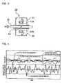
- Fig. 16A is a perspective view of a known gyroscopic apparatus
- Fig. 16B is an elevation view of the known gyroscopic apparatus.
- a gyroscopic apparatus 1 is formed by a gyro sensor 2.
- the gyro sensor 2 contains a stem 3 which has pin terminals 3a, a cover 4 mounted on the stem 3, and a vibrator 5 which is a vibrating mass arranged in the interior of a casing sealed by the stem 3 and the cover 4.
- the vibrator 5 is located at a position offset to the stem 3 in the casing. Descriptions of a supporting member for supporting the vibrator 5 in the air and a circuit portion for causing the vibrator 5 to vibrate and for processing a signal output from the vibrator 5 are omitted.
- Fig. 17 shows the structure of the vibrator 5.
- the vibrator 5 is formed by attaching, with an intermediate electrode 5F therebetween, a piezoelectric substrate 5U which is polarized in the thickness direction and which contains detecting electrodes 5L and 5R on a first principal surface thereof and a piezoelectric substrate 5D which is polarized in the thickness direction and which contains a common electrode 5C on a first principal surface thereof, thus bonding second principal surfaces of the piezoelectric substrates 5U and 5D.
- the vibrator 5 By applying a drive signal to the common electrode 5C, the vibrator 5 generates both-end-free bending vibrations in the thickness direction (the same as the thickness direction of the piezoelectric substrates 5U and 5D).
- an angular velocity to the vibrator 5 in the longitudinal direction (the same as the longitudinal direction of the piezoelectric substrates 5U and 5D) as a rotation axis (rotation detecting axis)
- the Coriolis force generates both-end-free bending vibrations in the width direction (the same as the width direction of the piezoelectric substrates 5U and 5D). Due to the bending vibrations in the width direction, signals in opposite directions are generated at the detecting electrodes 5L and 5R. From these signals, the magnitude and the direction of the angular velocity can be detected.
- Fig. 18 shows the relationship between the acceleration of impact applied randomly to the gyroscopic apparatus 1 arranged as described above in the direction indicated by the outline arrow of Fig. 16B and the output of the gyroscopic apparatus 1.
- An angular velocity applied to the gyroscopic apparatus 1 is constant.
- the output of the gyroscopic apparatus 1 fluctuates greatly in accordance with the impact, and the output includes an error signal. It is understood that the output of the gyroscopic apparatus 1 is susceptible to the impact.
- a gyroscopic apparatus includes first and second gyro sensors having the same structure; and an adder for adding the outputs of the first and second gyro sensors.
- the first and second gyro sensors are arranged so that signals output in response to an angular velocity applied thereto have the same sign and that signals output in response to an impact applied thereto have the opposite signs.
- the first and second gyro sensors may be arranged to have a 180-degree rotation symmetry about a virtual rotation axis which is in the direction of rotation detecting axes.
- the second gyro sensor may be arranged at a position given by parallel translating the first gyro sensor which is rotated by 180 degrees about a virtual rotation axis which is in the direction of rotation detecting axes.
- a gyroscopic apparatus includes first and second gyro sensors having the same structure; and a subtracter for obtaining the difference between the outputs of the first and second gyro sensors.
- the first and second gyro sensors are arranged so that signals output in response to an angular velocity applied thereto have the opposite signs and that signals output in response to an impact applied thereto have the same sign.
- the first and second gyro sensors may be arranged to have a 180-degree rotation symmetry about a virtual rotation axis which is orthogonal to rotation detecting axes.
- the second gyro sensor may be arranged at a position given by parallel translating the first gyro sensor which is rotated by 180 degrees about a virtual rotation axis which is orthogonal to rotation detecting axes.
- the gyroscopic apparatus may further include a mounting base, wherein the first gyro sensor may be placed on a first principal surface of the mounting base and the second gyro sensor may be placed on a second principal surface of the mounting base.
- the gyroscopic apparatus may further include a mounting base, wherein the first and second gyro sensors may be placed on one of surfaces of the mounting base.
- the first and second gyro sensors may include vibrating gyroscopes having vibrating masses.
- An electronic apparatus uses the foregoing gyroscopic apparatus.
- a highly accurate output can be obtained in response to an impact from a specific direction.
- performance enhancement can be achieved.
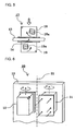
- Fig. 1 is a perspective view of a gyroscopic apparatus according to a first embodiment of the present invention.
- a gyroscopic apparatus 10 contains two gyro sensors 11 and 12 having the same structure and a mounting base 13 on which the gyro sensors 11 and 12 are mounted.
- the structure of the gyro sensors 11 and 12 is the same as that of the gyro sensor 2 of the known gyroscopic apparatus 1 shown in Figs. 16A and 16B.
- the gyro sensors 11 and 12 contain vibrators 11a and 12a (not shown), respectively.
- an adder is provided on the mounting base 13.
- the adder is connected to the two gyro sensors 11 and 12 and adds signals output from the two gyro sensors 11 and 12.
- a description of the adder is omitted.
- the gyro sensor 11 and the gyro sensor 12 are arranged on a first principal surface and a second principal surface, respectively, of the mounting base 13 so that rotation detecting axes are in the same direction (upward in Fig. 1) and that the gyro sensors 11 and 12 are opposed to each other.
- the positional relationship of the gyro sensor 12 with the gyro sensor 11 is such that the gyro sensors 11 and 12 have a 180-degree rotation symmetry about a virtual rotation axis 14 penetrating the mounting base 13 parallel thereto in the same direction as the rotation detecting axes.
- quadrangular marks are placed on three faces near a specific corner of each casing of the gyro sensors 11 and 12 in order that the positional relationship between the two gyro sensors 11 and 12 can be easily recognized.
- similar marks are placed in the drawings for the same purpose, although descriptions thereof are omitted.
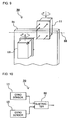
- Fig. 2 is a block diagram of the gyro sensor 10 shown in Fig. 1. As shown in Fig. 2, the gyro sensor 10 contains the two gyro sensors 11 and 12 and an adder 15 for adding the outputs of the two gyro sensors 11 and 12.
- the gyro sensor 11 when an angular velocity is applied in the direction of the rotation detecting axes, the gyro sensor 11 outputs a DC voltage signal whose sign varies in accordance with the direction of the angular velocity and whose voltage varies in accordance with the magnitude of the angular velocity. Since the direction of the rotation detecting axis of the gyro sensor 12 is the same as that of the gyro sensor 11, the gyro sensor 12 outputs a signal of the same magnitude, with the same sign as that of the gyro sensor 11.
- the adder 15 adds the signals and outputs the sum, i.e., a double value.
- Fig. 3 is an elevation view of the gyroscopic apparatus 10 (viewed from the direction of the rotation detecting axes). Using Fig. 3, the operation of the gyroscopic apparatus 10 to which an impact is applied will be considered. Fig. 3 shows the vibrators 11a and 12a, which are not shown in Fig. 1.
- the vibrator 11a When an impact is applied to the gyroscopic apparatus 10 from the left, that is, in the direction indicated by the outline arrow of Fig. 3, in the gyro sensor 11, the vibrator 11a is displaced in the counter clockwise direction since the vibrator 11a is arranged at a position offset to the stem in the casing. A rotational component included in the displacement is added to the original output obtained by the angular velocity and is output. In contrast, in the gyro sensor 12, the vibrator 12a is displaced in the clockwise direction. A rotational component included in the displacement is added to the original output obtained by the angular velocity and is output. In the gyro sensors 11 and 12, the absolute values of the added signal components due to the same impact are substantially equal.
- the rotational components due to the impact applied to the vibrators 11a and 12a are in the opposite directions.
- the signal components due to the impact have the opposite signs.
- the signal components are added by the adder 15, the signal components are canceled out.
- the output of the gyroscopic apparatus 10 is not influenced by the impact.
- Fig. 4 shows the relationship of the acceleration of the impact applied randomly to the gyroscopic apparatus 10 arranged as described above in the direction indicated by the outline arrow of Fig. 3 with the outputs of the gyroscopic apparatus 10 and the gyro sensors 11 and 12.
- the output of the gyroscopic apparatus 10 is reduced to half.
- An angular velocity applied to the gyroscopic apparatus 19 is constant.
- the outputs of the gyro sensors 11 and 12 fluctuate greatly due to the impact. Since the fluctuations are in the opposite directions, the output of the gyroscopic apparatus 10, namely, the sum of the two outputs, fluctuates little. Thus, the output of the gyroscopic apparatus 10 is not susceptible to the impact.
- the output of the gyroscopic apparatus 10 becomes less susceptible to impact from a specific direction.
- the two gyro sensors 11 and 12 are arranged to have a 180-degree rotation symmetry about the virtual rotation axis which is in the direction of the rotation detecting axes.
- the gyro sensor 12 can be arranged at a position given by parallel translating the gyro sensor 11 which is rotated by 180 degrees about the virtual rotation axis, which is in the direction of the rotation detecting axes, that is, by parallel translating the gyro sensor 11 having the precise symmetry along a mounting surface of the mounting base 13.
- Fig. 5 is an elevation view of a gyroscopic apparatus according to a second embodiment of the present invention.
- the same reference numerals are given to the same components or to components corresponding to those in Fig. 3, and descriptions of the common portions are omitted.
- a gyroscopic apparatus 17 contains gyro sensors 18 and 19, instead of the gyro sensors 11 and 12 in the gyroscopic apparatus 10.
- the gyro sensors 17 and 18 contain vibrators 18a and 19a, respectively.
- the structure of the gyro sensors 18 and 19 is the same as that of the gyro sensor 11 and 12.
- the gyro sensors 18 and 19 only differ from the gyro sensors 11 and 12 in that the vibrators 18a and 19a are located at positions offset in the width direction in the casings.
- the positional relationship of the gyro sensor 19 with the gyro sensor 18 is such that the gyro sensors 18 and 19 have a 180-degree rotation symmetry about the virtual rotation axis 14 penetrating the mounting base 13 parallel thereto in the same direction as the rotation detecting axes.
- the gyroscopic apparatus 17 shown in Fig. 5 when an angular velocity in the direction of the rotation detecting axis is applied, the gyro sensors 18 and 19 output signals of equal magnitude with the same sign.
- An adder (not shown) adds the signals and outputs the sum, namely, a double value.
- the vibrator 18a When an impact is applied to the gyroscopic apparatus 17 arranged as described above from the top, that is, in the direction indicated by the outline arrow of Fig. 5, in the gyro sensor 18, the vibrator 18a is displaced in the clockwise direction since the vibrator 18a is arranged at a position offset in the width direction in the casing. A rotational component included in the displacement is added to the original output obtained by the angular velocity and is output. In contrast, in the gyro sensor 19, the vibrator 19a is displaced in the counter clockwise direction. A rotational component included in the displacement is added to the original output obtained by the angular velocity and is output. In the gyro sensors 18 and 19, the absolute values of the added signal components due to the same impact are substantially equal.
- the rotational components due to the impact applied to the vibrators 18a and 19a are in the opposite directions.
- the signal components due to the impact have the opposite sings.
- the signal components are added by the adder (not shown), the signal components are canceled out.
- the output of the gyroscopic apparatus 17 is not influenced by the impact.
- the output of the gyroscopic apparatus 17 becomes less susceptible to impact from a specific direction.
- Fig. 6 is a perspective view of a gyroscopic apparatus according to a third embodiment of the present invention.
- the same reference numerals are given to the same components or to components corresponding to those in Fig. 1, and descriptions of the common portions are omitted.
- a gyroscopic apparatus 20 is formed by the two gyro sensors 11 and 12 having the same structure and the mounting base 13 on which the gyro sensors 11 and 12 are mounted.
- the gyro sensors 11 and 12 are mounted on the second principal surface of the mounting base 13 so that the rotation detecting axes are in the same direction and that the gyro sensors 11 and 12 are mounted on the mounting base 13 at the back and the front, respectively.
- the positional relationship of the gyro sensor 12 with the gyro sensor 11 is such that the gyro sensors 11 and 12 have a 180-degree rotation symmetry about a virtual rotation axis 21 penetrating, between the gyro sensors 11 and 12, the mounting base 13 parallel thereto in the same direction as the rotation detecting axes.
- pin terminals of the gyro sensor 12 mounted at the back thereof onto the mounting base 13 are illustrated such that the pin terminals are not connected to the mounting base 13 in order that the positional relationship can be easily recognized. Actually, the pin terminals are somehow connected to an adder, which will not be described. A description of the connection relationship is omitted.
- the gyroscopic apparatus 20 shown in Fig. 6 when an angular velocity in the direction of the rotation detecting axes is applied, the gyro sensors 11 and 12 output signals of equal magnitude with the same sign.
- the adder (not shown) adds the signals and outputs the sum, that is, a double value.
- Fig. 7 is an elevation view of the gyroscopic apparatus 20 (viewed in the direction of the rotation detecting axes). Using Fig. 7, the operation of the gyroscopic apparatus 20 to which impact is applied will be considered.
- the vibrator 11a When impact is applied to the gyroscopic apparatus 20 from the left, that is, in the direction indicated by the outline arrow of Fig. 7, in the gyro sensor 11, the vibrator 11a is displaced in the counter clockwise direction since the vibrator 11a is located at a position offset to the stem in the casing. A rotational component included in the displacement is added to the original output obtained by the angular velocity and is output. In contrast, in the gyro sensor 12, the vibrator 12a is displaced in the clockwise direction. A rotational component included in the displacement is added to the original output obtained by the angular velocity and is output. In the gyro sensors 11 and 12, the absolute values of the added signal components due to the same impact are substantially equal.
- the rotational components due to the impact applied to the vibrators 11a and 12a are in the opposite directions.
- the signal components due to the impact have the opposite signs.
- the adder not shown
- the signal components are canceled out.
- the output of the gyroscopic apparatus 20 is not influenced by the impact.
- the output of the gyroscopic apparatus 20 becomes less susceptible to impact from a specific direction.
- the gyro sensor 12 can be arranged at a position given by rotating by 180 degrees the gyro sensor 11 round the virtual rotation axis in the direction of the rotation detecting axis, that is, at a position given by parallel translating the gyro sensor 11 from the precisely symmetric position along the mounting surface of the mounting base 13. With this arrangement, the operation equivalent to that in a case where two gyro sensors are placed at positions having a precise symmetry, as in the gyroscopic apparatus 20, can be achieved.
- Fig. 8 is an elevation view of a gyroscopic apparatus according to a fourth embodiment of the present invention.
- a gyroscopic apparatus 22 contains the gyro sensors 18 and 19 shown in Fig. 5, instead of the gyro sensors 11 and 12 of the gyroscopic apparatus 20 shown in Figs. 6 and 7.
- the same reference numerals are given to the same components or to components corresponding to those in Figs. 5 to 7, and descriptions of the common portions are omitted.
- the positional relationship of the gyro sensor 19 with the gyro sensor 18 is such that the gyro sensors 18 and 19 have a 180-degree rotation symmetry about the virtual rotation axis 21 penetrating, between the gyro sensors 18 and 19, the mounting base 13 parallel thereto in the same direction as the rotation detecting axes.
- the gyro sensors 18 and 19 output signals of equal magnitude with the same sign.
- An adder (not shown) adds the signals and outputs the sum, that is, a double value.
- the vibrator 18a When impact is applied to the gyroscopic apparatus 22 arranged as described above from the top, that is, in the direction indicated by the outline arrow of Fig. 8, in the gyro sensor 18, the vibrator 18a is displaced in the clockwise direction since the vibrator 18a is placed at a position offset in the width direction in the casing. A rotational component included in the displacement is added to the original output obtained by the angular velocity and is output. In contrast, in the gyro sensor 19, the vibrator 19a is displaced in the counter clockwise direction. A rotational component included in the displacement is added to the original output obtained by the angular velocity and is output. In the gyro sensors 18 and 19, the absolute values of the added signal components due to the same impact are substantially equal.
- the rotational components due to the impact applied to the vibrators 18a and 19a are in the opposite directions.
- the signal components due to the impact have the opposite signs.
- the adder not shown
- the signal components are canceled out.
- the output of the gyroscopic apparatus 22 is not influenced by the impact.
- the output of the gyroscopic apparatus 22 is not influenced by impact from a specific direction.
- Fig. 9 is a perspective view of a gyroscopic apparatus according to a fifth embodiment of the present invention.
- the same reference numerals are given to the same components or to components corresponding to those in Fig. 1, and descriptions of the common portions are omitted.
- a gyroscopic apparatus 30 contains the two gyro sensors 11 and 12 having the same structure and a mounting base 31 on which the gyro sensors 11 and 12 are mounted.
- the gyro sensors 11 and 12 are mounted on a first principal surface and a second principal surface, respectively, of the mounting base 31, so that the rotation detecting axes are in the opposite directions and that the gyro sensors 11 and 12 are opposed to each other.
- the positional relationship of the gyro sensor 12 with the gyro sensor 11 is such that the gyro sensors 11 and 12 have a 180-degree rotation symmetry about a virtual rotation axis 33 penetrating the mounting base 31 parallel thereto in the direction orthogonal to the rotation detecting axes.
- a subtracter for computing the difference between signals output from the two gyro sensors 11 and 12 is provided on the mounting base 31. A description of the subtracter is omitted here.
- Fig. 10 is a block diagram of the gyroscopic apparatus 30 shown in Fig. 9. As shown in Fig. 10, the gyroscopic apparatus 30 contains the two gyro sensors 11 and 12 and a subtracter 32 for computing the difference between the outputs of the gyro sensors 11 and 12.
- the gyro sensors 11 and 12 When an angular velocity in the direction of the rotation detecting axes is applied to the gyroscopic apparatus 30 shown in Figs. 9 and 10, the gyro sensors 11 and 12 output signals of the same magnitude, with the opposite signs.
- the subtracter 32 computes the difference between the output signals and outputs the difference, that is, a double value.
- Fig. 11 is an elevation view of the gyroscopic apparatus 30 (viewed in the direction of the rotation detecting axes). Using Fig. 11, the operation of the gyroscopic apparatus 30 to which impact is applied will be considered.
- the vibrator 11a When impact is applied to the gyroscopic apparatus 30 from the left, that is, in the direction indicated by the outline arrow of Fig. 11, in the gyro sensor 11, the vibrator 11a is displaced in the counter clockwise direction since the vibrator 11a is placed at a position offset to the stem in the casing. A rotational component included in the displacement is added to the original output obtained by the angular velocity and is output. In contrast, in the gyro sensor 12, the vibrator 12a is displaced in the clockwise direction. A rotational component included in the displacement is added to the original output obtained by the angular velocity and is output.
- the angular-velocity detecting axes i.e., the rotation detecting axes
- the rotational components generated by the impact are in the same direction with respect to the angular-velocity rotation axes.
- the absolute values of the added signal components due to the same impact are substantially equal.
- the rotational components due to the impact applied to the vibrators 11a and 12a are in the same direction.
- the signal components due to the impact have the same sign.
- the difference between the signal components is computed by subtracter 32, the signal components are canceled out.
- the output of the gyroscopic apparatus 30 is not influenced by the impact.
- Fig. 12 shows the relationship of the acceleration of impact applied randomly to the gyroscopic apparatus 30 arranged as described above in the direction indicated by the outline arrow of Fig. 11 with the outputs of the gyroscopic apparatus 30 and the gyro sensors 11 and 12.
- each output is represented by the absolute value, and the output of the gyroscopic apparatus 30 is reduced to half.
- An angular velocity applied to the gyroscopic apparatus 30 is constant.
- the outputs of the gyro sensors 11 and 12 fluctuate greatly due to the impact. Since the fluctuations are in the same direction, the output of the gyroscopic apparatus 30, that is, the difference between the two outputs, fluctuates little. Thus, the output of the gyroscopic apparatus 30 is not susceptible to impact.
- the output of the gyroscopic apparatus 30 becomes less susceptible to impact from a specific direction.
- the output of the gyroscopic apparatus 30 remains susceptible to impact.
- the gyro sensor 12 can be arranged at a position given by rotating by 180 degrees the gyro sensor 11 round the virtual rotation axis orthogonal to the rotation detecting axis, that is, at a position given by parallel translating the gyro sensor 11 from the precisely symmetric position along the mounting surface of the mounting base 31.
- the operation equivalent to that in a case where two gyro sensors are placed at positions having a precise symmetry, as in the gyroscopic apparatus 30, can be achieved.
- Fig. 13 is a perspective view of a gyroscopic apparatus according to a sixth embodiment of the present invention.
- a gyroscopic apparatus 40 contains the gyro sensors 18 and 19 shown in Fig. 5, instead of the gyro sensors 11 and 12 of the gyroscopic apparatus 30 shown in Fig. 9.
- the same reference numerals are given to the same components or to components corresponding to those in Figs. 5 and 9, and descriptions of the common portions are omitted.
- the gyroscopic apparatus 40 contains the two gyro sensors 18 and 19 having the same structure and the mounting substrate 31 on which the gyro sensors 18 and 19 are mounted.
- the gyro sensor 18 and the gyro sensor 19 are mounted next to each other on the second principal surface of the mounting base 31 such that the rotation detecting axes are in the opposite directions.
- the positional relationship of the gyro sensor 19 with the gyro sensor 18 is such that the gyro sensors 18 and 19 are arranged to have a 180-degree rotation symmetry about a virtual rotation axis 41 which is orthogonal to the rotation detecting axes and which penetrates the mounting base 31 in the thickness direction between the gyro sensors 18 and 19.
- the gyroscopic apparatus 40 shown in Fig. 13 when an angular velocity is applied in the direction of the rotation detecting axes, the gyro sensors 18 and 19 output signals of equal magnitude with the opposite signs.
- a subtracter (not shown) obtains the difference between the output signals and outputs the difference, namely, a double value.
- Fig. 14 is an elevation view of the gyroscopic apparatus 40 (viewed from the direction of the rotation detecting axes). Using Fig. 14, the operation of the gyroscopic apparatus 40 to which impact is applied will be considered.
- the vibrator 18a When impact is applied to the gyroscopic apparatus 40 from the top, that is, in the direction indicated by the outline arrow of Fig. 14, in the gyro sensor 18, the vibrator 18a is displaced in the clockwise direction since the vibrator 18a is placed at a position offset to the right in the casing. A rotational component included in the displacement is added to the original output obtained by the angular velocity and is output. In contrast, in the gyro sensor 19, the vibrator 19a is displaced in the counter clockwise direction. A rotational component included in the displacement is added to the original output obtained by the angular velocity and is output.
- the angular-velocity detecting axes that is, the rotation detecting axes
- the rotational components generated by the impact are in the same direction with respect to the angular-velocity detecting axes.
- the absolute values of the added signal components added due to the same impact are substantially equal.
- the rotational components due to the impact applied to the vibrators 18a and 19a are in the same direction.
- the signal components due to the impact have the same sign.
- the difference between the signal components is computed by the subtracter (not shown), the signal components are canceled output. Accordingly, the output of the gyroscopic apparatus 40 is not influenced by the impact.
- the output of the gyroscopic apparatus 40 becomes less susceptible to impact from a specific direction.
- the output of the gyroscopic apparatus 40 remains susceptible to impact.
- the gyro sensor 19 can be arranged at a position given by rotating by 180 degrees the gyro sensor 18 round the virtual rotation axis orthogonal to the rotation detecting axes, that is, at a position given by parallel translating the gyro sensor 18 from the precisely symmetric position along the mounting surface of the mounting base 31.
- the operation equivalent to that in a case where two gyro sensors are placed at positions having a precise symmetry, as in the gyroscopic apparatus 40 can be achieved.
- Fig. 15 is a perspective view of a video camera which is an embodiment of an electronic apparatus according to the present invention.
- a video camera 50 contains the vibrating gyroscope 10 of the present invention for compensating for camera movement caused by an unsteady hand.
- the gyroscopic apparatus 10 in which a malfunction due to impact is less likely to occur is used.
- the performance of the video camera 50 can be improved.
- An example of the electronic apparatus of the present invention is not limited to the video camera.
- the electronic apparatus of the present invention is applicable to any electronic apparatus using the vibrating gyroscope, such as a digital camera which similarly uses the vibrating gyroscope for compensating for camera movement caused by an unsteady hand, a navigation apparatus which uses the vibrating gyroscope for detecting a position, a vehicle-rollover detector, and a vehicle-attitude detector.
Abstract
Description
- The present invention relates to a gyroscopic apparatus and an electronic apparatus using the same, such as a gyroscopic apparatus used for detecting a vehicle rollover, vehicle attitude, and camera movement caused by an unsteady hand and to an electronic apparatus using the same.
- Various types of gyroscopic apparatuses used for detecting a vehicle rollover, vehicle attitude, and camera movement caused by an unsteady hand have been proposed. For example, Japanese Unexamined Patent Application Publication No. 7-332988 discloses a gyroscopic apparatus using a gyro sensor which uses a vibrator formed by attaching two piezoelectric substrates which are polarized in the opposite directions.
- In this gyro sensor, the vibrator which is held in the air by a supporting member is caused to bend and vibrate in the thickness direction (the same as the thickness direction of the piezoelectric substrates) while both ends thereof are free. When an angular velocity is applied to the gyro sensor in the longitudinal direction (the same as the longitudinal direction of the piezoelectric substrates) as a rotation axis, bending vibrations in the vibrator width direction are generated by a Coriolis force. From the bending vibrations, the direction and magnitude of the angular velocity are detected.
- Fig. 16A is a perspective view of a known gyroscopic apparatus, and Fig. 16B is an elevation view of the known gyroscopic apparatus. Referring to Figs. 16A and 16B, a gyroscopic apparatus 1 is formed by a
gyro sensor 2. Thegyro sensor 2 contains astem 3 which haspin terminals 3a, acover 4 mounted on thestem 3, and avibrator 5 which is a vibrating mass arranged in the interior of a casing sealed by thestem 3 and thecover 4. Thevibrator 5 is located at a position offset to thestem 3 in the casing. Descriptions of a supporting member for supporting thevibrator 5 in the air and a circuit portion for causing thevibrator 5 to vibrate and for processing a signal output from thevibrator 5 are omitted. - Fig. 17 shows the structure of the
vibrator 5. Thevibrator 5 is formed by attaching, with anintermediate electrode 5F therebetween, apiezoelectric substrate 5U which is polarized in the thickness direction and which contains detectingelectrodes piezoelectric substrate 5D which is polarized in the thickness direction and which contains acommon electrode 5C on a first principal surface thereof, thus bonding second principal surfaces of thepiezoelectric substrates - By applying a drive signal to the
common electrode 5C, thevibrator 5 generates both-end-free bending vibrations in the thickness direction (the same as the thickness direction of thepiezoelectric substrates vibrator 5 in the longitudinal direction (the same as the longitudinal direction of thepiezoelectric substrates piezoelectric substrates electrodes - Referring again to Fig. 16B, when an impact is applied to the gyroscopic apparatus 1 arranged as described above in the direction indicated by the outline arrow, since the
vibrator 5 is placed at an offset position, thevibrator 5 is temporarily displaced to a vibrator 5' of Fig. 16B due to an elastic deformation of the supporting member and deformation of a cushion. For example, when the gyroscopic apparatus 1 is installed in a vehicle, such an impact is generated in the vertical direction of the vehicle caused by unevenness of a road surface. Although not shown, when the direction of the impact is reversed, the displacement of thevibrator 5 is also reversed. Since the displacement includes a rotational component indicated by the arrow in Fig. 16B, the output of the gyro sensor fluctuates. The larger the offset (positional offset) of thevibrator 5 in the casing formed by thestem 3 and thecover 4, the more noticeable the fluctuation becomes. - Fig. 18 shows the relationship between the acceleration of impact applied randomly to the gyroscopic apparatus 1 arranged as described above in the direction indicated by the outline arrow of Fig. 16B and the output of the gyroscopic apparatus 1. An angular velocity applied to the gyroscopic apparatus 1 is constant. As is clear from Fig. 18, the output of the gyroscopic apparatus 1 fluctuates greatly in accordance with the impact, and the output includes an error signal. It is understood that the output of the gyroscopic apparatus 1 is susceptible to the impact.
- When the output of the gyroscopic apparatus 1 includes an error signal, an accurate angular velocity cannot be detected.
- In order to solve the foregoing problems, it is an object of the present invention to provide a gyroscopic apparatus capable of detecting an accurate angular velocity even when an external impact is applied thereto and an electronic apparatus using the same.
- In order to achieve the foregoing objects, a gyroscopic apparatus according to an aspect of the present invention includes first and second gyro sensors having the same structure; and an adder for adding the outputs of the first and second gyro sensors. The first and second gyro sensors are arranged so that signals output in response to an angular velocity applied thereto have the same sign and that signals output in response to an impact applied thereto have the opposite signs.
- The first and second gyro sensors may be arranged to have a 180-degree rotation symmetry about a virtual rotation axis which is in the direction of rotation detecting axes.
- The second gyro sensor may be arranged at a position given by parallel translating the first gyro sensor which is rotated by 180 degrees about a virtual rotation axis which is in the direction of rotation detecting axes.
- A gyroscopic apparatus according to another aspect of the present invention includes first and second gyro sensors having the same structure; and a subtracter for obtaining the difference between the outputs of the first and second gyro sensors. The first and second gyro sensors are arranged so that signals output in response to an angular velocity applied thereto have the opposite signs and that signals output in response to an impact applied thereto have the same sign.
- The first and second gyro sensors may be arranged to have a 180-degree rotation symmetry about a virtual rotation axis which is orthogonal to rotation detecting axes.
- The second gyro sensor may be arranged at a position given by parallel translating the first gyro sensor which is rotated by 180 degrees about a virtual rotation axis which is orthogonal to rotation detecting axes.
- The gyroscopic apparatus may further include a mounting base, wherein the first gyro sensor may be placed on a first principal surface of the mounting base and the second gyro sensor may be placed on a second principal surface of the mounting base.
- The gyroscopic apparatus may further include a mounting base, wherein the first and second gyro sensors may be placed on one of surfaces of the mounting base.
- The first and second gyro sensors may include vibrating gyroscopes having vibrating masses.
- An electronic apparatus according to an aspect of the present invention uses the foregoing gyroscopic apparatus.
- Arranged as described above, according to a gyroscopic apparatus of the present invention, a highly accurate output can be obtained in response to an impact from a specific direction.
- According to an electronic apparatus of the present invention, performance enhancement can be achieved.
-
- Fig. 1 is a perspective view of a gyroscopic apparatus according to a first embodiment of the present invention;
- Fig. 2 is a block diagram of the gyroscopic apparatus shown in Fig. 1;
- Fig. 3 is an elevation view of the gyroscopic apparatus shown in Fig. 1;
- Fig. 4 is a characteristic diagram showing the relationship between the acceleration of impact applied to the gyroscopic apparatus shown in Fig. 1 and the output thereof;
- Fig. 5 is an elevation view of a gyroscopic apparatus according to a second embodiment of the present invention;
- Fig. 6 is a perspective view of a gyroscopic apparatus according to a third embodiment of the present invention;
- Fig. 7 is an elevation view of the gyroscopic apparatus shown in Fig. 6;
- Fig. 8 is an elevation view of a gyroscopic apparatus according to a fourth embodiment of the present invention;
- Fig. 9 is a perspective view of a gyroscopic apparatus according to a fifth embodiment of the present invention;
- Fig. 10 is a block diagram of the gyroscopic apparatus shown in Fig. 9;
- Fig. 11 is an elevation view of the gyroscopic apparatus shown in Fig. 9;
- Fig. 12 is a characteristic diagram showing the relationship between the acceleration of impact applied to the gyroscopic apparatus shown in Fig. 9 and the output thereof;
- Fig. 13 is a perspective view of a gyroscopic apparatus according to a sixth embodiment of the present invention;
- Fig. 14 is an elevation view of the gyroscopic apparatus shown in Fig. 13;
- Fig. 15 is a perspective view of an embodiment of an electronic apparatus according to the present invention;
- Fig. 16A is a perspective view and Fig. 16B is an elevation view of a known gyroscopic apparatus;
- Fig. 17 is a perspective view of a vibrator used in the gyroscopic apparatus shown in Fig. 16; and
- Fig. 18 is a characteristic diagram showing the relationship between the acceleration of impact applied to the gyroscopic apparatus shown in Fig. 16 and the output thereof.
-
- Fig. 1 is a perspective view of a gyroscopic apparatus according to a first embodiment of the present invention. Referring to Fig. 1, a
gyroscopic apparatus 10 contains twogyro sensors base 13 on which thegyro sensors gyro sensors gyro sensor 2 of the known gyroscopic apparatus 1 shown in Figs. 16A and 16B. Thegyro sensors vibrators base 13. The adder is connected to the twogyro sensors gyro sensors - The
gyro sensor 11 and thegyro sensor 12 are arranged on a first principal surface and a second principal surface, respectively, of the mountingbase 13 so that rotation detecting axes are in the same direction (upward in Fig. 1) and that thegyro sensors gyro sensor 12 with thegyro sensor 11 is such that thegyro sensors virtual rotation axis 14 penetrating the mountingbase 13 parallel thereto in the same direction as the rotation detecting axes. In Fig. 1, quadrangular marks are placed on three faces near a specific corner of each casing of thegyro sensors gyro sensors - Fig. 2 is a block diagram of the
gyro sensor 10 shown in Fig. 1. As shown in Fig. 2, thegyro sensor 10 contains the twogyro sensors adder 15 for adding the outputs of the twogyro sensors - In the
gyro sensor 10 shown in Figs. 1 and 2, when an angular velocity is applied in the direction of the rotation detecting axes, thegyro sensor 11 outputs a DC voltage signal whose sign varies in accordance with the direction of the angular velocity and whose voltage varies in accordance with the magnitude of the angular velocity. Since the direction of the rotation detecting axis of thegyro sensor 12 is the same as that of thegyro sensor 11, thegyro sensor 12 outputs a signal of the same magnitude, with the same sign as that of thegyro sensor 11. Theadder 15 adds the signals and outputs the sum, i.e., a double value. - Fig. 3 is an elevation view of the gyroscopic apparatus 10 (viewed from the direction of the rotation detecting axes). Using Fig. 3, the operation of the
gyroscopic apparatus 10 to which an impact is applied will be considered. Fig. 3 shows thevibrators - When an impact is applied to the
gyroscopic apparatus 10 from the left, that is, in the direction indicated by the outline arrow of Fig. 3, in thegyro sensor 11, thevibrator 11a is displaced in the counter clockwise direction since thevibrator 11a is arranged at a position offset to the stem in the casing. A rotational component included in the displacement is added to the original output obtained by the angular velocity and is output. In contrast, in thegyro sensor 12, thevibrator 12a is displaced in the clockwise direction. A rotational component included in the displacement is added to the original output obtained by the angular velocity and is output. In thegyro sensors gyro sensors vibrators adder 15, the signal components are canceled out. Thus, the output of thegyroscopic apparatus 10 is not influenced by the impact. - Fig. 4 shows the relationship of the acceleration of the impact applied randomly to the
gyroscopic apparatus 10 arranged as described above in the direction indicated by the outline arrow of Fig. 3 with the outputs of thegyroscopic apparatus 10 and thegyro sensors gyroscopic apparatus 10 is reduced to half. An angular velocity applied to thegyroscopic apparatus 19 is constant. As is clear from Fig. 4, the outputs of thegyro sensors gyroscopic apparatus 10, namely, the sum of the two outputs, fluctuates little. Thus, the output of thegyroscopic apparatus 10 is not susceptible to the impact. - According to the
gyroscopic apparatus 10, by arranging the twogyro sensors gyroscopic apparatus 10 becomes less susceptible to impact from a specific direction. - According to the
gyroscopic apparatus 10, the twogyro sensors gyro sensor 12 can be arranged at a position given by parallel translating thegyro sensor 11 which is rotated by 180 degrees about the virtual rotation axis, which is in the direction of the rotation detecting axes, that is, by parallel translating thegyro sensor 11 having the precise symmetry along a mounting surface of the mountingbase 13. With this arrangement, the operation equivalent to that in a case where two gyro sensors have precise symmetry, as in the gyroscopic apparatus 1, can be achieved. - Fig. 5 is an elevation view of a gyroscopic apparatus according to a second embodiment of the present invention. In Fig. 5, the same reference numerals are given to the same components or to components corresponding to those in Fig. 3, and descriptions of the common portions are omitted.
- Referring to Fig. 5, a
gyroscopic apparatus 17 containsgyro sensors gyro sensors gyroscopic apparatus 10. Thegyro sensors vibrators gyro sensors gyro sensor gyro sensors gyro sensors vibrators gyro sensor 19 with thegyro sensor 18 is such that thegyro sensors virtual rotation axis 14 penetrating the mountingbase 13 parallel thereto in the same direction as the rotation detecting axes. - In the
gyroscopic apparatus 17 shown in Fig. 5, when an angular velocity in the direction of the rotation detecting axis is applied, thegyro sensors - When an impact is applied to the
gyroscopic apparatus 17 arranged as described above from the top, that is, in the direction indicated by the outline arrow of Fig. 5, in thegyro sensor 18, thevibrator 18a is displaced in the clockwise direction since thevibrator 18a is arranged at a position offset in the width direction in the casing. A rotational component included in the displacement is added to the original output obtained by the angular velocity and is output. In contrast, in thegyro sensor 19, thevibrator 19a is displaced in the counter clockwise direction. A rotational component included in the displacement is added to the original output obtained by the angular velocity and is output. In thegyro sensors gyro sensors vibrators gyroscopic apparatus 17 is not influenced by the impact. - According to the
gyroscopic apparatus 17, by arranging the twogyro sensors gyroscopic apparatus 17 becomes less susceptible to impact from a specific direction. - Fig. 6 is a perspective view of a gyroscopic apparatus according to a third embodiment of the present invention. In Fig. 6, the same reference numerals are given to the same components or to components corresponding to those in Fig. 1, and descriptions of the common portions are omitted.
- Referring to Fig. 6, a
gyroscopic apparatus 20 is formed by the twogyro sensors base 13 on which thegyro sensors gyro sensors base 13 so that the rotation detecting axes are in the same direction and that thegyro sensors base 13 at the back and the front, respectively. The positional relationship of thegyro sensor 12 with thegyro sensor 11 is such that thegyro sensors virtual rotation axis 21 penetrating, between thegyro sensors base 13 parallel thereto in the same direction as the rotation detecting axes. In thegyroscopic apparatus 20, pin terminals of thegyro sensor 12 mounted at the back thereof onto the mountingbase 13 are illustrated such that the pin terminals are not connected to the mountingbase 13 in order that the positional relationship can be easily recognized. Actually, the pin terminals are somehow connected to an adder, which will not be described. A description of the connection relationship is omitted. - In the
gyroscopic apparatus 20 shown in Fig. 6, when an angular velocity in the direction of the rotation detecting axes is applied, thegyro sensors - Fig. 7 is an elevation view of the gyroscopic apparatus 20 (viewed in the direction of the rotation detecting axes). Using Fig. 7, the operation of the
gyroscopic apparatus 20 to which impact is applied will be considered. - When impact is applied to the
gyroscopic apparatus 20 from the left, that is, in the direction indicated by the outline arrow of Fig. 7, in thegyro sensor 11, thevibrator 11a is displaced in the counter clockwise direction since thevibrator 11a is located at a position offset to the stem in the casing. A rotational component included in the displacement is added to the original output obtained by the angular velocity and is output. In contrast, in thegyro sensor 12, thevibrator 12a is displaced in the clockwise direction. A rotational component included in the displacement is added to the original output obtained by the angular velocity and is output. In thegyro sensors vibrators gyroscopic apparatus 20 is not influenced by the impact. - According to the
gyroscopic apparatus 20, by arranging the twogyro sensors gyroscopic apparatus 20 becomes less susceptible to impact from a specific direction. - According to the
gyroscopic apparatus 20, thegyro sensor 12 can be arranged at a position given by rotating by 180 degrees thegyro sensor 11 round the virtual rotation axis in the direction of the rotation detecting axis, that is, at a position given by parallel translating thegyro sensor 11 from the precisely symmetric position along the mounting surface of the mountingbase 13. With this arrangement, the operation equivalent to that in a case where two gyro sensors are placed at positions having a precise symmetry, as in thegyroscopic apparatus 20, can be achieved. - Fig. 8 is an elevation view of a gyroscopic apparatus according to a fourth embodiment of the present invention. Referring to Fig. 8, a
gyroscopic apparatus 22 contains thegyro sensors gyro sensors gyroscopic apparatus 20 shown in Figs. 6 and 7. In Fig. 8, the same reference numerals are given to the same components or to components corresponding to those in Figs. 5 to 7, and descriptions of the common portions are omitted. - In the
gyroscopic apparatus 22 shown in Fig. 8, the positional relationship of thegyro sensor 19 with thegyro sensor 18 is such that thegyro sensors virtual rotation axis 21 penetrating, between thegyro sensors base 13 parallel thereto in the same direction as the rotation detecting axes. When an angular velocity in the direction of the rotation detecting axes is applied, thegyro sensors - When impact is applied to the
gyroscopic apparatus 22 arranged as described above from the top, that is, in the direction indicated by the outline arrow of Fig. 8, in thegyro sensor 18, thevibrator 18a is displaced in the clockwise direction since thevibrator 18a is placed at a position offset in the width direction in the casing. A rotational component included in the displacement is added to the original output obtained by the angular velocity and is output. In contrast, in thegyro sensor 19, thevibrator 19a is displaced in the counter clockwise direction. A rotational component included in the displacement is added to the original output obtained by the angular velocity and is output. In thegyro sensors vibrators gyroscopic apparatus 22 is not influenced by the impact. - According to the
gyroscopic apparatus 22, by arranging the twogyro sensors gyroscopic apparatus 22 is not influenced by impact from a specific direction. - Fig. 9 is a perspective view of a gyroscopic apparatus according to a fifth embodiment of the present invention. In Fig. 9, the same reference numerals are given to the same components or to components corresponding to those in Fig. 1, and descriptions of the common portions are omitted.
- Referring to Fig. 9, a
gyroscopic apparatus 30 contains the twogyro sensors base 31 on which thegyro sensors gyro sensors base 31, so that the rotation detecting axes are in the opposite directions and that thegyro sensors gyro sensor 12 with thegyro sensor 11 is such that thegyro sensors virtual rotation axis 33 penetrating the mountingbase 31 parallel thereto in the direction orthogonal to the rotation detecting axes. As described below, a subtracter for computing the difference between signals output from the twogyro sensors base 31. A description of the subtracter is omitted here. - Fig. 10 is a block diagram of the
gyroscopic apparatus 30 shown in Fig. 9. As shown in Fig. 10, thegyroscopic apparatus 30 contains the twogyro sensors subtracter 32 for computing the difference between the outputs of thegyro sensors - When an angular velocity in the direction of the rotation detecting axes is applied to the
gyroscopic apparatus 30 shown in Figs. 9 and 10, thegyro sensors subtracter 32 computes the difference between the output signals and outputs the difference, that is, a double value. - Fig. 11 is an elevation view of the gyroscopic apparatus 30 (viewed in the direction of the rotation detecting axes). Using Fig. 11, the operation of the
gyroscopic apparatus 30 to which impact is applied will be considered. - When impact is applied to the
gyroscopic apparatus 30 from the left, that is, in the direction indicated by the outline arrow of Fig. 11, in thegyro sensor 11, thevibrator 11a is displaced in the counter clockwise direction since thevibrator 11a is placed at a position offset to the stem in the casing. A rotational component included in the displacement is added to the original output obtained by the angular velocity and is output. In contrast, in thegyro sensor 12, thevibrator 12a is displaced in the clockwise direction. A rotational component included in the displacement is added to the original output obtained by the angular velocity and is output. In thegyro sensors gyro sensors gyro sensors vibrators subtracter 32, the signal components are canceled out. The output of thegyroscopic apparatus 30 is not influenced by the impact. - Fig. 12 shows the relationship of the acceleration of impact applied randomly to the
gyroscopic apparatus 30 arranged as described above in the direction indicated by the outline arrow of Fig. 11 with the outputs of thegyroscopic apparatus 30 and thegyro sensors gyroscopic apparatus 30 is reduced to half. An angular velocity applied to thegyroscopic apparatus 30 is constant. As is clear from Fig. 12, the outputs of thegyro sensors gyroscopic apparatus 30, that is, the difference between the two outputs, fluctuates little. Thus, the output of thegyroscopic apparatus 30 is not susceptible to impact. - According to the
gyroscopic apparatus 30, by arranging the twogyro sensors gyroscopic apparatus 30 becomes less susceptible to impact from a specific direction. - In the
gyroscopic apparatus 30 arranged as described above, when gyro sensors, such as thegyro sensors gyroscopic apparatus 30 remains susceptible to impact. - According to the
gyroscopic apparatus 30, thegyro sensor 12 can be arranged at a position given by rotating by 180 degrees thegyro sensor 11 round the virtual rotation axis orthogonal to the rotation detecting axis, that is, at a position given by parallel translating thegyro sensor 11 from the precisely symmetric position along the mounting surface of the mountingbase 31. With this arrangement, the operation equivalent to that in a case where two gyro sensors are placed at positions having a precise symmetry, as in thegyroscopic apparatus 30, can be achieved. - Fig. 13 is a perspective view of a gyroscopic apparatus according to a sixth embodiment of the present invention. Referring to Fig. 13, a
gyroscopic apparatus 40 contains thegyro sensors gyro sensors gyroscopic apparatus 30 shown in Fig. 9. In Fig. 13, the same reference numerals are given to the same components or to components corresponding to those in Figs. 5 and 9, and descriptions of the common portions are omitted. - Referring to Fig. 13, the
gyroscopic apparatus 40 contains the twogyro sensors substrate 31 on which thegyro sensors gyro sensor 18 and thegyro sensor 19 are mounted next to each other on the second principal surface of the mountingbase 31 such that the rotation detecting axes are in the opposite directions. The positional relationship of thegyro sensor 19 with thegyro sensor 18 is such that thegyro sensors virtual rotation axis 41 which is orthogonal to the rotation detecting axes and which penetrates the mountingbase 31 in the thickness direction between thegyro sensors - According to the
gyroscopic apparatus 40 shown in Fig. 13, when an angular velocity is applied in the direction of the rotation detecting axes, thegyro sensors - Fig. 14 is an elevation view of the gyroscopic apparatus 40 (viewed from the direction of the rotation detecting axes). Using Fig. 14, the operation of the
gyroscopic apparatus 40 to which impact is applied will be considered. - When impact is applied to the
gyroscopic apparatus 40 from the top, that is, in the direction indicated by the outline arrow of Fig. 14, in thegyro sensor 18, thevibrator 18a is displaced in the clockwise direction since thevibrator 18a is placed at a position offset to the right in the casing. A rotational component included in the displacement is added to the original output obtained by the angular velocity and is output. In contrast, in thegyro sensor 19, thevibrator 19a is displaced in the counter clockwise direction. A rotational component included in the displacement is added to the original output obtained by the angular velocity and is output. In thegyro sensors gyro sensors gyro sensor vibrators gyroscopic apparatus 40 is not influenced by the impact. - According to the
gyroscopic apparatus 40, by arranging the twogyro sensors gyroscopic apparatus 40 becomes less susceptible to impact from a specific direction. - In the
gyroscopic apparatus 40 arranged as described above, when gyro sensors, such as thegyro sensors gyroscopic apparatus 40 remains susceptible to impact. - According to the
gyroscopic apparatus 40, thegyro sensor 19 can be arranged at a position given by rotating by 180 degrees thegyro sensor 18 round the virtual rotation axis orthogonal to the rotation detecting axes, that is, at a position given by parallel translating thegyro sensor 18 from the precisely symmetric position along the mounting surface of the mountingbase 31. With this arrangement, the operation equivalent to that in a case where two gyro sensors are placed at positions having a precise symmetry, as in thegyroscopic apparatus 40, can be achieved. - Fig. 15 is a perspective view of a video camera which is an embodiment of an electronic apparatus according to the present invention. Referring to Fig. 15, a
video camera 50 contains the vibratinggyroscope 10 of the present invention for compensating for camera movement caused by an unsteady hand. - In the
video camera 50 arranged as described above, thegyroscopic apparatus 10 in which a malfunction due to impact is less likely to occur is used. Thus, the performance of thevideo camera 50 can be improved. - An example of the electronic apparatus of the present invention is not limited to the video camera. The electronic apparatus of the present invention is applicable to any electronic apparatus using the vibrating gyroscope, such as a digital camera which similarly uses the vibrating gyroscope for compensating for camera movement caused by an unsteady hand, a navigation apparatus which uses the vibrating gyroscope for detecting a position, a vehicle-rollover detector, and a vehicle-attitude detector.
Claims (10)
- A gyroscopic apparatus comprising:wherein the first and second gyro sensors are arranged so that signals output in response to an angular velocity applied thereto have the same sign and that signals output in response to an impact applied thereto have the opposite signs.first and second gyro sensors having the same structure; andadding means for adding the outputs of the first and second gyro sensors,
- A gyroscopic apparatus according to Claim 1, wherein the first and second gyro sensors are arranged to have a 180-degree rotation symmetry about a virtual rotation axis which is in the direction of rotation detecting axes.
- A gyroscopic apparatus according to Claim 1, wherein the second gyro sensor is arranged at a position given by parallel translating the first gyro sensor which is rotated by 180 degrees about a virtual rotation axis which is in the direction of rotation detecting axes.
- A gyroscopic apparatus comprising:wherein the first and second gyro sensors are arranged so that signals output in response to an angular velocity applied thereto have the opposite signs and that signals output in response to an impact applied thereto have the same sign.first and second gyro sensors having the same structure; andsubtracting means for obtaining the difference between the outputs of the first and second gyro sensors,
- A gyroscopic apparatus according to Claim 4, wherein the first and second gyro sensors are arranged to have a 180-degree rotation symmetry about a virtual rotation axis which is orthogonal to rotation detecting axes.
- A gyroscopic apparatus according to Claim 4, wherein the second gyro sensor is arranged at a position given by parallel translating the first gyro sensor which is rotated by 180 degrees about a virtual rotation axis which is orthogonal to rotation detecting axes.
- A gyroscopic apparatus according to Claim 1 or 4, further comprising a mounting base, wherein the first gyro sensor is placed on a first principal surface of the mounting base and the second gyro sensor is placed on a second principal surface of the mounting base.
- A gyroscopic apparatus according to Claim 1 or 4, further comprising a mounting base, wherein the first and second gyro sensors are placed on one of surfaces of the mounting base.
- A gyroscopic apparatus according to Claim 1 or 4, wherein the first and second gyro sensors comprise vibrating gyroscopes having vibrating masses.
- An electronic apparatus using a gyroscopic apparatus as set forth in Claim 1 or 4.
Applications Claiming Priority (2)
| Application Number | Priority Date | Filing Date | Title |
|---|---|---|---|
| JP2001100180A JP2002296039A (en) | 2001-03-30 | 2001-03-30 | Gyro device and electronic device using the same |
| JP2001100180 | 2001-03-30 |
Publications (2)
| Publication Number | Publication Date |
|---|---|
| EP1245928A1 true EP1245928A1 (en) | 2002-10-02 |
| EP1245928B1 EP1245928B1 (en) | 2013-02-27 |
Family
ID=18953648
Family Applications (1)
| Application Number | Title | Priority Date | Filing Date |
|---|---|---|---|
| EP02007171A Expired - Lifetime EP1245928B1 (en) | 2001-03-30 | 2002-03-28 | Gyroscopic apparatus and electronic apparatus using the same |
Country Status (3)
| Country | Link |
|---|---|
| US (1) | US6796177B2 (en) |
| EP (1) | EP1245928B1 (en) |
| JP (1) | JP2002296039A (en) |
Cited By (4)
| Publication number | Priority date | Publication date | Assignee | Title |
|---|---|---|---|---|
| US7055254B1 (en) | 2004-11-24 | 2006-06-06 | Universitat Bremen | Tiltsensor |
| WO2006121586A1 (en) * | 2005-05-09 | 2006-11-16 | Northrop Grumman Corporation | Sensor orientation for environmental error reduction |
| EP1872087A2 (en) * | 2005-04-19 | 2008-01-02 | Jaymart Sensors, Llc | Miniaturized inertial measurement unit and associated methods |
| RU2626312C1 (en) * | 2016-03-28 | 2017-07-25 | Владимир Евгеньевич Скворцов | Gyroscopic device |
Families Citing this family (28)
| Publication number | Priority date | Publication date | Assignee | Title |
|---|---|---|---|---|
| US7749089B1 (en) | 1999-02-26 | 2010-07-06 | Creative Kingdoms, Llc | Multi-media interactive play system |
| US7878905B2 (en) | 2000-02-22 | 2011-02-01 | Creative Kingdoms, Llc | Multi-layered interactive play experience |
| US6761637B2 (en) | 2000-02-22 | 2004-07-13 | Creative Kingdoms, Llc | Method of game play using RFID tracking device |
| US7445550B2 (en) | 2000-02-22 | 2008-11-04 | Creative Kingdoms, Llc | Magical wand and interactive play experience |
| US7066781B2 (en) | 2000-10-20 | 2006-06-27 | Denise Chapman Weston | Children's toy with wireless tag/transponder |
| US6967566B2 (en) | 2002-04-05 | 2005-11-22 | Creative Kingdoms, Llc | Live-action interactive adventure game |
| US20070066396A1 (en) | 2002-04-05 | 2007-03-22 | Denise Chapman Weston | Retail methods for providing an interactive product to a consumer |
| US7674184B2 (en) | 2002-08-01 | 2010-03-09 | Creative Kingdoms, Llc | Interactive water attraction and quest game |
| US9446319B2 (en) | 2003-03-25 | 2016-09-20 | Mq Gaming, Llc | Interactive gaming toy |
| JP2005283481A (en) * | 2004-03-30 | 2005-10-13 | Denso Corp | Sensor system |
| JP2006105598A (en) * | 2004-09-30 | 2006-04-20 | Honda Motor Co Ltd | Acceleration/angular velocity sensor unit |
| US7650238B2 (en) * | 2005-05-09 | 2010-01-19 | Northrop Grumman Corporation | Environmental characteristic determination |
| JP4805633B2 (en) | 2005-08-22 | 2011-11-02 | 任天堂株式会社 | Game operation device |
| US8313379B2 (en) | 2005-08-22 | 2012-11-20 | Nintendo Co., Ltd. | Video game system with wireless modular handheld controller |
| US7927216B2 (en) | 2005-09-15 | 2011-04-19 | Nintendo Co., Ltd. | Video game system with wireless modular handheld controller |
| JP4262726B2 (en) | 2005-08-24 | 2009-05-13 | 任天堂株式会社 | Game controller and game system |
| US8870655B2 (en) | 2005-08-24 | 2014-10-28 | Nintendo Co., Ltd. | Wireless game controllers |
| US8308563B2 (en) | 2005-08-30 | 2012-11-13 | Nintendo Co., Ltd. | Game system and storage medium having game program stored thereon |
| US8157651B2 (en) | 2005-09-12 | 2012-04-17 | Nintendo Co., Ltd. | Information processing program |
| JP4151982B2 (en) | 2006-03-10 | 2008-09-17 | 任天堂株式会社 | Motion discrimination device and motion discrimination program |
| JP5013250B2 (en) * | 2006-07-20 | 2012-08-29 | セイコーエプソン株式会社 | Acceleration sensor |
| JP5133550B2 (en) * | 2006-10-18 | 2013-01-30 | ペンタックスリコーイメージング株式会社 | Gyro sensor mounting structure for camera with camera shake correction function |
| JP5127242B2 (en) | 2007-01-19 | 2013-01-23 | 任天堂株式会社 | Acceleration data processing program and game program |
| WO2009112526A1 (en) * | 2008-03-11 | 2009-09-17 | Continental Teves Ag & Co. Ohg | Sensor device for detecting at least one rotation rate of a rotating motion |
| JP5320862B2 (en) * | 2008-07-01 | 2013-10-23 | 株式会社デンソー | Sensor device |
| JP2010191316A (en) * | 2009-02-20 | 2010-09-02 | Fujifilm Corp | Shake detecting sensor and image blur correcting device |
| JP5318720B2 (en) * | 2009-09-30 | 2013-10-16 | 富士通テン株式会社 | Electronic control unit |
| US9182211B2 (en) * | 2011-12-06 | 2015-11-10 | Honeywell International Inc. | Field interchangable boresight mounting system and calibration method |
Citations (7)
| Publication number | Priority date | Publication date | Assignee | Title |
|---|---|---|---|---|
| EP0664438A1 (en) | 1994-01-25 | 1995-07-26 | The Charles Stark Draper Laboratory, Inc. | Comb drive micromechanical tuning fork gyro |
| WO1995034798A1 (en) * | 1994-06-16 | 1995-12-21 | Robert Bosch Gmbh | Accelerometer |
| US5703293A (en) | 1995-05-27 | 1997-12-30 | Robert Bosch Gmbh | Rotational rate sensor with two acceleration sensors |
| US5895850A (en) | 1994-04-23 | 1999-04-20 | Robert Bosch Gmbh | Micromechanical resonator of a vibration gyrometer |
| US5962786A (en) * | 1995-09-26 | 1999-10-05 | Onera (Office National D'eudes Et De Recheres Aerospatiales) | Monolithic accelerometric transducer |
| EP0971208A2 (en) | 1998-07-10 | 2000-01-12 | Murata Manufacturing Co., Ltd. | Angular velocity sensor |
| WO2002016871A1 (en) | 2000-08-18 | 2002-02-28 | Hahn-Schickard Gesellschaft Für Angewandte Forschung E.V. | Rotation speed sensor and rotation speed sensor system |
Family Cites Families (4)
| Publication number | Priority date | Publication date | Assignee | Title |
|---|---|---|---|---|
| US4791815A (en) * | 1986-04-11 | 1988-12-20 | Matsushita Electric Industrial Co., Ltd. | Cyclically driven gyro and adjusting system therefor |
| JPH05240874A (en) * | 1991-12-06 | 1993-09-21 | Canon Inc | Angular-velocity sensor |
| JP2780643B2 (en) | 1994-06-03 | 1998-07-30 | 株式会社村田製作所 | Vibrating gyro |
| JP2003028644A (en) * | 2001-07-12 | 2003-01-29 | Denso Corp | Angular velocity sensor |
-
2001
- 2001-03-30 JP JP2001100180A patent/JP2002296039A/en active Pending
-
2002
- 2002-03-15 US US10/097,982 patent/US6796177B2/en not_active Expired - Lifetime
- 2002-03-28 EP EP02007171A patent/EP1245928B1/en not_active Expired - Lifetime
Patent Citations (7)
| Publication number | Priority date | Publication date | Assignee | Title |
|---|---|---|---|---|
| EP0664438A1 (en) | 1994-01-25 | 1995-07-26 | The Charles Stark Draper Laboratory, Inc. | Comb drive micromechanical tuning fork gyro |
| US5895850A (en) | 1994-04-23 | 1999-04-20 | Robert Bosch Gmbh | Micromechanical resonator of a vibration gyrometer |
| WO1995034798A1 (en) * | 1994-06-16 | 1995-12-21 | Robert Bosch Gmbh | Accelerometer |
| US5703293A (en) | 1995-05-27 | 1997-12-30 | Robert Bosch Gmbh | Rotational rate sensor with two acceleration sensors |
| US5962786A (en) * | 1995-09-26 | 1999-10-05 | Onera (Office National D'eudes Et De Recheres Aerospatiales) | Monolithic accelerometric transducer |
| EP0971208A2 (en) | 1998-07-10 | 2000-01-12 | Murata Manufacturing Co., Ltd. | Angular velocity sensor |
| WO2002016871A1 (en) | 2000-08-18 | 2002-02-28 | Hahn-Schickard Gesellschaft Für Angewandte Forschung E.V. | Rotation speed sensor and rotation speed sensor system |
Cited By (5)
| Publication number | Priority date | Publication date | Assignee | Title |
|---|---|---|---|---|
| US7055254B1 (en) | 2004-11-24 | 2006-06-06 | Universitat Bremen | Tiltsensor |
| EP1872087A2 (en) * | 2005-04-19 | 2008-01-02 | Jaymart Sensors, Llc | Miniaturized inertial measurement unit and associated methods |
| EP1872087A4 (en) * | 2005-04-19 | 2012-10-17 | Jaymart Sensors Llc | Miniaturized inertial measurement unit and associated methods |
| WO2006121586A1 (en) * | 2005-05-09 | 2006-11-16 | Northrop Grumman Corporation | Sensor orientation for environmental error reduction |
| RU2626312C1 (en) * | 2016-03-28 | 2017-07-25 | Владимир Евгеньевич Скворцов | Gyroscopic device |
Also Published As
| Publication number | Publication date |
|---|---|
| EP1245928B1 (en) | 2013-02-27 |
| US6796177B2 (en) | 2004-09-28 |
| JP2002296039A (en) | 2002-10-09 |
| US20020139186A1 (en) | 2002-10-03 |
Similar Documents
| Publication | Publication Date | Title |
|---|---|---|
| US6796177B2 (en) | Gyroscopic apparatus and electronic apparatus including same | |
| US6810735B2 (en) | Sensing apparatus and electronic equipment using the sensing apparatus | |
| JP5205725B2 (en) | Angular velocity sensor | |
| US7363815B2 (en) | Angular velocity sensor | |
| JP2009002735A (en) | Angular velocity detector | |
| JP5306570B2 (en) | Vibrating gyro | |
| US8453503B2 (en) | Vibrating reed, vibrator, physical quantity sensor, and electronic apparatus | |
| US11181547B2 (en) | Inertial sensor, electronic device, and vehicle | |
| JP5050448B2 (en) | Angular velocity sensor and electronic device | |
| US6694813B2 (en) | Vibrating gyroscope and electronic unit using the same | |
| JP2009222475A (en) | Compound sensor | |
| JP2007322200A (en) | Inertial sensor element | |
| JP3336451B2 (en) | Tuning fork type vibration gyro | |
| JP2006145420A (en) | Angular speed detection system | |
| US5578754A (en) | Vibration-type angular-velocity sensor | |
| JP2002243450A (en) | Angular velocity sensor, acceleration sensor and angular velocity/acceleration sensor | |
| CN1928496A (en) | Angular velocity sensor | |
| JP4858215B2 (en) | Compound sensor | |
| JP2003166828A (en) | Physical quantity measuring device and vibrator | |
| JP3783697B2 (en) | Two-axis detection type twin tone vibration gyro sensor | |
| JP4441165B2 (en) | Electrode structure of angular velocity detection sensor element | |
| JP7099284B2 (en) | Inertia sensors, electronic devices and moving objects | |
| JP2009192403A (en) | Angular velocity and acceleration detector | |
| JPWO2005052601A1 (en) | Acceleration detector | |
| JP2007142938A (en) | Portable information terminal apparatus |
Legal Events
| Date | Code | Title | Description |
|---|---|---|---|
| PUAI | Public reference made under article 153(3) epc to a published international application that has entered the european phase |
Free format text: ORIGINAL CODE: 0009012 |
|
| 17P | Request for examination filed |
Effective date: 20020328 |
|
| AK | Designated contracting states |
Kind code of ref document: A1 Designated state(s): AT BE CH CY DE DK ES FI FR GB GR IE IT LI LU MC NL PT SE TR |
|
| AX | Request for extension of the european patent |
Free format text: AL;LT;LV;MK;RO;SI |
|
| AKX | Designation fees paid |
Designated state(s): DE FR GB |
|
| RAP1 | Party data changed (applicant data changed or rights of an application transferred) |
Owner name: MURATA MANUFACTURING CO., LTD. |
|
| 17Q | First examination report despatched |
Effective date: 20090612 |
|
| GRAP | Despatch of communication of intention to grant a patent |
Free format text: ORIGINAL CODE: EPIDOSNIGR1 |
|
| GRAC | Information related to communication of intention to grant a patent modified |
Free format text: ORIGINAL CODE: EPIDOSCIGR1 |
|
| GRAS | Grant fee paid |
Free format text: ORIGINAL CODE: EPIDOSNIGR3 |
|
| GRAA | (expected) grant |
Free format text: ORIGINAL CODE: 0009210 |
|
| AK | Designated contracting states |
Kind code of ref document: B1 Designated state(s): DE FR GB |
|
| REG | Reference to a national code |
Ref country code: GB Ref legal event code: FG4D |
|
| REG | Reference to a national code |
Ref country code: DE Ref legal event code: R096 Ref document number: 60244548 Country of ref document: DE Effective date: 20130425 |
|
| PLBE | No opposition filed within time limit |
Free format text: ORIGINAL CODE: 0009261 |
|
| STAA | Information on the status of an ep patent application or granted ep patent |
Free format text: STATUS: NO OPPOSITION FILED WITHIN TIME LIMIT |
|
| GBPC | Gb: european patent ceased through non-payment of renewal fee |
Effective date: 20130527 |
|
| 26N | No opposition filed |
Effective date: 20131128 |
|
| REG | Reference to a national code |
Ref country code: DE Ref legal event code: R097 Ref document number: 60244548 Country of ref document: DE Effective date: 20131128 |
|
| PG25 | Lapsed in a contracting state [announced via postgrant information from national office to epo] |
Ref country code: GB Free format text: LAPSE BECAUSE OF NON-PAYMENT OF DUE FEES Effective date: 20130527 |
|
| PG25 | Lapsed in a contracting state [announced via postgrant information from national office to epo] |
Ref country code: FR Free format text: LAPSE BECAUSE OF NON-PAYMENT OF DUE FEES Effective date: 20130331 |
|
| PGFP | Annual fee paid to national office [announced via postgrant information from national office to epo] |
Ref country code: DE Payment date: 20210319 Year of fee payment: 20 |
|
| REG | Reference to a national code |
Ref country code: DE Ref legal event code: R071 Ref document number: 60244548 Country of ref document: DE |