EP1247268B2 - Low power two-wire self validating temperature transmitter - Google Patents
Low power two-wire self validating temperature transmitter Download PDFInfo
- Publication number
- EP1247268B2 EP1247268B2 EP00943314A EP00943314A EP1247268B2 EP 1247268 B2 EP1247268 B2 EP 1247268B2 EP 00943314 A EP00943314 A EP 00943314A EP 00943314 A EP00943314 A EP 00943314A EP 1247268 B2 EP1247268 B2 EP 1247268B2
- Authority
- EP
- European Patent Office
- Prior art keywords
- temperature
- transmitter
- microprocessor
- wire
- related information
- Prior art date
- Legal status (The legal status is an assumption and is not a legal conclusion. Google has not performed a legal analysis and makes no representation as to the accuracy of the status listed.)
- Expired - Lifetime
Links
Images

Classifications
-
- G—PHYSICS
- G08—SIGNALLING
- G08C—TRANSMISSION SYSTEMS FOR MEASURED VALUES, CONTROL OR SIMILAR SIGNALS
- G08C19/00—Electric signal transmission systems
- G08C19/02—Electric signal transmission systems in which the signal transmitted is magnitude of current or voltage
Landscapes
- Physics & Mathematics (AREA)
- General Physics & Mathematics (AREA)
- Arrangements For Transmission Of Measured Signals (AREA)
- Measuring Temperature Or Quantity Of Heat (AREA)
- Feedback Control In General (AREA)
Description
- The process industry employs process variable transmitters to monitor process variables associated with substances such as solids, slurries, liquids, vapors, and gasses in chemical, pulp, petroleum, pharmaceutical, food and other processing plants. Process variables include pressure, temperature, flow, level, turbidity, density, concentration, chemical composition and other properties.
- In typical processing plants, a communication bus, such as a 4-20 mA current loop is used to power the process variable transmitter. Examples of such current loops include a FOUNDATION™ Fieldbus connection or a connection in accordance with the Highway Addressable Remote Transducer - (HART) communication protocol. In transmitters powered by a two-wire loop, power must be kept low to comply with intrinsic safety requirements.
- A process temperature transmitter provides an output related to a sensed process substance temperature. The temperature transmitter output can be communicated over the loop to a control room, or the output can be communicated to another process device such that the process can be monitored and controlled. In order to monitor a process temperature, the transmitter includes a sensor, such as a resistance temperature device (RTD) or a thermocouple.
- An RTD changes resistance in response to a change in temperature. By measuring the resistance of the RTD, temperature can be calculated. Such resistance measurement is generally accomplished by passing a known current through the RTD, and measuring the associated voltage developed across the RTD.
- A thermocouple provides a voltage in response to a temperature change. The Seebeck Effect provides that dissimilar metal junctions create voltage due to the union of the dissimilar metals in a temperature gradient condition. Thus, the voltage measured across the thermocouple will relate to the temperature of the thermocouple.
- As temperature sensors age, their accuracy tends to degrade until the sensor ultimately fails. However, small degradations in the output from the sensor are difficult to detect and to separate from actual changes in the measured temperature. In the past, temperature transmitters have used two temperature sensors to detect sensor degradation. If the output from the two sensors is not in agreement, the temperature transmitter can provide an error output. However, this technique is not able to detect a degradation in the sensor output if both of the two temperature sensors degrade at the same rate and in the same manner.
- One technique which has been used in situations in which power is not a constraint is described in
U.S. Patent Nos. 5,713,668 and5,887,978 , issued February 3, 1998 and March 30, 1999, respectively, to Lunghofer et al. and entitled "SELF-VERIFYING TEMPERATURE SENSOR". These references describe a temperature sensor having multiple outputs. The multiple outputs all vary as functions of temperature. However, the relationships between the various outputs and temperature are not the same. - A further proposal is disclosed in
U.S. Patent No. 5,469,156 which describes a field sensor communication system in which a field sensor communicates with an "upper level" unit, which may be a receiver or a communication unit.
Further, the various elements in the temperature sensor change over time at differing rates, and in differing manners and react differently to various types of failures. A computer monitors the output from the sensor using a multiplexer. The computer places data points from the sensor into a matrix. By monitoring the various entries in the matrix and detecting changes in the various element or elements of the matrix relative to other elements, the computer provides a "confidence level" output for the measured temperature. If the confidence level exceeds a threshold, an alarm can be provided. - However, the art of low power process variable transmitters has an ongoing need for improved temperature sensors such as those which provide improved accuracy or a diagnostic output indicative of the condition of the temperature sensor.
- The present invention provides a two-wire transmitter coupleable to a two-wire process control loop for measuring temperature of a process, the transmitter comprising power supply means coupleable to the two-wire process control loop to supply power uniquely via the two-wire loop to the temperature transmitter; loop communication means configured to at least send information over the two-wire process control loop; temperature sensing means; measurement means coupled to the temperature sensing means to provide data indicative of a temperature of the temperature sensing means; and computing means comprising a microprocessor, the computing means being coupled to the measurement means; characterized in that the temperature sensing means comprises a temperature sensor comprising at least two temperature sensitive elements each having element -outputs which elements degrade in accordance with different degradation characteristics; the computing means is operable to compute a process temperature based upon at least two temperature sensitive elements having different degradation characteristics; the transmitter further comprises an analog to digital converter coupled to the element outputs and configured to provide digital output in response to an analog input; and the microprocessor is coupled to the digital output and is configured to send temperature related information on the two-wire process control loop via the two-wire loop communicator, wherein the microprocessor calculates temperature related information as a function of at least one element output from a first temperature sensitive element and at least as a function of one degradation characteristic of at least a second temperature sensitive element, and each of the first temperature sensitive element and second temperature sensitive element are weighted with a weight that varies with the rate of change of the process temperature.
- A method of measuring process temperature with a two-wire temperature transmitter, the method comprising measuring a primary sensor element of a temperature sensor with the two-wire temperature transmitter, to provide a primary sensor signal; providing the primary signal to a transmitter microprocessor; calculating a process temperature based at least upon the primary sensor element; calculating a confidence level of the process temperature based upon the primary sensor signal; and providing a validated process temperature output based on the temperature output and the confidence level; and characterized by measuring at least one secondary sensor element with the two-wire temperature transmitter to obtain at least one secondary sensor signal; providing the secondary sensor signal to the transmitter microprocessor; and calculating, using the transmitter microprocessor, the process temperature and the confidence level based on the primary sensor signal and one or more secondary sensor signals, wherein the weighting of the primary sensor signal and the one or more secondary sensor signals is varied according to the rate of change of the process temperature itself when calculating the process temperature.
- In accordance with a preferred embodiment of the present invention, a two-wire temperature transmitter is coupleable to a two-wire process control loop for measuring a process temperature. The transmitter includes an analog to digital converter configured to provide digital output in response to an analog input. A two-wire loop communicator is configured to couple to the process control loop and send information on the loop. A microprocessor is coupled to the digital output and configured to send temperature related information on the process control loop with the two-wire loop communicator. A power supply is configured to completely power the two-wire process control loop. A temperature sensor comprises at least two temperature sensitive element shaving element outputs which degrade in accordance with different degradation characteristics. The element outputs are provided to the analog to digital converter, such that the microprocessor calculates temperature related information as a function of at least one element output from a first temperature sensitive element and at least as a function of one degradation characteristic of a second temperature sensitive element.
-
-
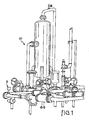
FIG. 1 is a diagram of the environment of a process temperature transmitter. -
FIG. 2 is a diagrammatic view of the process temperature transmitter ofFIG. 1 . -
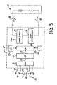
FIG. 3 is a system block diagram of a process temperature transmitter. -
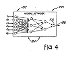
FIG. 4 is a diagram of a neural network implemented in the transmitter ofFIG. 3 . -
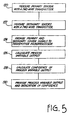
FIG. 5 is a block diagram of a method of measuring process fluid temperature with a two-wire process temperature transmitter. -
FIGS. 1 and2 illustrate the environment of a process temperature transmitter in accordance with embodiments of the invention. -
FIG. 2 illustratesprocess control system 10 includingprocess temperature transmitter 12 electrically coupled to monitor 14 (modelled as a voltage source and resistance) over two-wireprocess control loop 16. As used herein, two-wire process control loop means a communication channel including two wires that power connected process devices and provide for communication between the connected devices. -
Transmitter 12 is mounted on and coupled to a process fluid container such aspipe 18.Transmitter 12 monitors the temperature of process fluid inprocess pipe 18 and transmits temperature information to monitor 14 overloop 16. -
FIG. 3 is a system block diagram ofprocess temperature transmitter 12 in accordance with an embodiment of the invention.Process temperature transmitter 12 includes an analog to digital converter 20 configured to provide adigital output 22 in response to ananalog input 24. A two-wire loop communicator 26 is configured to couple to two-wireprocess control loop 16 and to send information onloop 16 from amicroprocessor 28. At least onepower supply 30 is configured to couple to loop 16 to receive power solely fromloop 16 and provide a power output (Pwr) to power circuitry intransmitter 12 with power received fromloop 16. Atemperature sensor 34 couples to analog to digital converter 20 throughmultiplexer 36 which provides theanalog signal 24.Temperature sensor 34 includes temperature sensitive elements such as RTD 40 andthermocouples Temperature sensor 34 operates in accordance with the techniques described inU.S. Patent No. 5,713,668 . In addition to the transmitter shown inFIG. 3 , the teachings ofU.S. Patent No. 5,828,567 to Eryurek et al., entitled "DIAGNOSTICS FOR RESISTANCE BASED TRANSMITTER" can be used withsensor 34. -
Microprocessor 28 can be a low power microprocessor such as a Motorola 6805HC11 available from Motorola Inc. In many microprocessor systems, amemory 50 is included in the microprocessor which operates at a rate determined byclock 52.Memory 50 includes both programming instructions formicroprocessor 28 as well as temporary storage for measurement values obtained fromtemperature sensor 34, for example. The frequency ofclock 52 can be reduced to further reduce power consumption ofmicroprocessor 28. -
Loop communicator 26 communicates on two-wireprocess control loop 16 in accordance.. with known protocols and techniques. For example,communicator 26 can adjust the loop current I in accordance with a process variable received frommicroprocessor 28 such that current I is related to the process variable. For example, a 4 mA current can represent a lower value of a process variable and 20 mA current can represent an upper value for the process variable. In another embodiment,communicator 26 impresses a digital signal onto loop current I and transmits information in a digital format. Further, such digital information can be received from two-wireprocess control loop 16 bycommunicator 26 and provided tomicroprocessor 28 to control operation oftemperature transmitter 12. - Analog to digital converter 20 operates under low power conditions. One example of analog to digital converter 20 is a sigma-delta converter. Examples of analog to digital converters used in process variable transmitters are described in
U.S. Patent No. 5,083,091 , entitled "CHARGE BALANCE FEEDBACK MEASUREMENT CIRCUIT" issued January 21, 1992 andU.S. Patent No. 4,878,012 , entitled "CHARGE BALANCE FEEDBACK TRANSMITTER, issued October 31, 1989, which are commonly assigned with the present application. -
Sensor 34 includes at least two temperature sensitive elements each having element outputs that degrade in accordance with different degradation characteristics. As illustrated,sensor 34 includesconductors conductors 60 and 62 can be of dissimilar metals such that they form a thermocouple atjunction 42. Usingmultiplexer 36, various voltage and resistance measurements ofsensor 34 can be made bymicroprocessor 28. Further, a four point Kelvin connection toRTD 40 throughconductors 60, 62, 66 and 68 is used to obtain an accurate measurement of the resistance ofRTD 40. In such a measurement, current is injected using, for example,conductors 60 and 68 intoRTD 40 and conductors 62 and 66 are used to make a voltage measurement.Conductor 64 can also be used to make a voltage measurement at some midpoint inRTD 40. Voltage measurements can also be made between any pair of conductors such asconductors 60/62, 60/64, 62/66, etc. Further still, various voltage or resistance measurements can be combined to obtain additional data for use bymicroprocessor 28. -
Microprocessor 28 stores the data points inmemory 50 and operates on the data in accordance with the techniques described inU.S. Patent Nos. 5,713,668 and5,887,978 . This is used to generate a process variable output related to temperature which is provided toloop communicator 26. For example, one of the elements insensor 34 such asRTD 40 can be the primary element while the remaining temperature related data points provide secondary data points.Microprocessor 28 can provide the process variable output along with an indication of the confidence level, probability of accuracy or a temperature range, i.e., plus or minus a certain temperature amount or percentage based upon the secondary data points. For example, the process variable output can be output as an analog signal (i.e., between 4 and 20 mA) while the indication of confidence can be provided as a digital signal. The confidence indication can be generated by empirical measurements in which all of the data outputs are observed over a wide range of temperatures and as the elements begin to degrade with time or other failures.Microprocessor 28 can compare actual measurements with the characteristics stored inmemory 50 which have been generated using the empirical tests. Using this technique, anomalous readings from one or more of the data measurements can be detected. Depending on the severity of the degradation,microprocessor 28 can correct the temperature output to compensate for the degraded element. For a severely degraded element,microprocessor 28 can indicate that thesensor 34 is failing and that the temperature output is inaccurate. -
Microprocessor 28 can also provide a process variable output as a function of the primary sensor element and one or more secondary sensor elements. For example, the primary sensor element can be an RTD indicating a temperature of for example 98°C while a secondary sensor element, for example a type J thermocouple, may indicate a temperature of 100°C, giving each sensor an equal numeric weight would provide a process temperature output of 99°C. Because various types of sensors and sensor families exhibit different electrical characteristics in varying temperature ranges,microprocessor 28 can be programmed to vary sensor element weighting based upon the process variable itself. Thus, as the measured temperature begins to exceed a useful range of one type of sensor, the weighting for that sensor can be reduced or eliminated such that additional sensors with higher useful temperature ranges can be relied upon. Moreover, because various types of sensors and sensor families have different time constants, it is contemplated that the weighting factors can be changed in response to a rate of change of the measured temperature. For example, an RTD generally has more thermal mass than a thermocouple due to the sheer mass of wound sensor wire and the fact that the sensor wire is generally wound around a ceramic bobbin which provides yet additional thermal mass. However, the thermocouple junctions may have significantly less thermal mass than the RTD and thus track rapid temperature changes more effectively than the RTD. Thus, asmicroprocessor 28 begins to detect a rapid temperature change the sensor element weights can be adjusted such that the process variable output relies more heavily upon thermocouples. - In one embodiment, software in
memory 50 is used to implement a neural network inmicroprocessor 28 such asneural network 100 illustrated inFIG. 4. FIG. 4 illustrates a multi-layer neural network.Neural network 100 can be trained using known training algorithms such as the back propagation network (BPN) to develop the neural network modules. The network includesinput nodes 102, hiddennodes 104 andoutput node 106. Various data measurements D1-DN are provided as inputs to theinput nodes 102 which act as an input buffer. Theinput nodes 102 modify the received data by various weights in accordance with a training algorithm and the outputs are provided to the hiddennodes 104. Thehidden layer 104 is used to characterize and analyze the non-linear properties of thesensor 34. The last layer, theoutput layer 106 provides anoutput 108 which is an indication of the accuracy of the temperature measurement. Similarly, an additional output can be used to provide an indication of the sensed temperature. - The
neural network 100 can be trained either through modeling or empirical techniques in which actual sensors are used to provide training inputs to theneural network 100. Additionally, a more probable estimate of the process temperature can be provided as the output based upon operation of the neural network upon the various sensor element signals. - Another technique for analyzing the data obtained from
sensor 34 is through the use of a rule based system in whichmemory 50 contains rules, expected results and sensitivity parameters. -
FIG. 5 is a block diagram of a method of measuring process temperature with a two-wire process temperature transmitter. The method begins atblock 120 where a primary sensor element is measured using a two-wire temperature transmitter, such astransmitter 12. Atblock 122, one or more secondary sensor elements are measured using the two-wire temperature transmitter. It should be noted thatblock 122 need not be performed after each and every primary sensor element measurement, but thatblock 122 can be performed periodically or in response to an external command. Atblock 124, the primary sensor element and secondary sensor element signals are provided to a transmitter microprocessor, such as microprocessor 28 (shown inFIG. 3 ). Atblock 126,microprocessor 28 calculates a process variable output based upon one or more of the primary sensor element signal and secondary sensor element signals. Atblock 128, the microprocessor calculates a confidence of the process variable output based upon the primary element sensor signal and one or more of the secondary sensor element signals. Finally, atblock 130, the process temperature output and an indication of output validation or confidence in the process temperature output are provided by the two-wire process temperature transmitter. Such indication can be in the form of a numeric value representing a tolerance, or probability of accuracy or a temperature range, i.e., plus or minus a certain temperature amount or percentage based upon one or more secondary sensor signals; or the indication can also be an alarm or other user notification representative of the acceptability of the process variable output. Additionally, the indication of confidence can be in the form of an estimation of time remaining until the two-wire process transmitter is unable to suitably relate the process variable output to the process temperature. Further, providing a validated process temperature allows validation and diagnostics of other process variables that can be affected by the process temperature. - Another analysis technique is fuzzy logic. For example, fuzzy logic algorithms can be employed on the data measurements D1-DN prior to their input into
neural network 100 ofFIG. 4 . Additionally,neural network 100 can implement a fuzzy-neural algorithm in which the various neurons of the network implement fuzzy algorithms. The various analysis techniques can be used alone or in their combinations. Additionally, other analysis techniques are considered to be within the scope of the present invention so long as they reach the requirement that the system is capable of operating completely from power received from a two-wire process control loop. - Although only a single analog to digital converter 20 is shown, such an analog to digital converter can comprise multiple analog to digital converters which can thereby either reduce or eliminate the amount of multiplexing performed when coupling the
sensor 34 to the analog to digital converters. - Although the invention has been described with reference to preferred embodiments, workers skilled in the art will recognize that changes can be made in form and detail without departing from the scope of the invention as defined by the claims. For example, various function blocks of the invention have been described in terms of circuitry, however, many function blocks may be implemented in other forms such as digital and analog circuits, software and their hybrids. When implemented in software, a microprocessor performs the functions and the signals comprise digital values on which the software operates. A general purpose processor programmed with instructions that cause the processor to perform the desired process elements, application specific hardware components that contain circuits wired to perform the desired elements and any combination of programing a general purpose processor and hardware- components can be used. Deterministic or fuzzy logic techniques can be used as needed to make decisions in the circuitry or software. Because of the nature of complex digital circuitry, circuit elements may not be partitioned into separate blocks as shown, but components used for various functional blocks can be intermingled and shared. Likewise with software, some instructions can be shared as part of several functions and be intermingled with unrelated instructions within the scope of the invention, as defined by the claims.
Claims (11)
- A two-wire transmitter (12) coupleable to a two-wire process control loop (16) for measuring temperature of a process, the transmitter comprising:power supply means (14) coupleable to the two-wire process control loop to supply power uniquely via the two-wire loop to the temperature transmitter;loop communication means (26) configured to at least send information over the two-wire process control loop;temperature sensing means (34);measurement means (28, 36) coupled to the temperature sensing means to provide data indicative of a temperature of the temperature sensing means; andcomputing means (28) comprising a microprocessor, the computing means being coupled to the measurement means;characterized in thatthe temperature sensing means (34) comprises a temperature sensor comprising at least two temperature sensitive elements (40, 42, 44, 46) each having element outputs which elements degrade in accordance with different degradation characteristics;the computing means is operable to compute a process temperature based upon at least two temperature sensitive elements having different degradation characteristics;the transmitter further comprises an analog to digital converter (20) coupled to the element outputs and configured to provide digital output in response to an analog input; andthe microprocessor (28) is coupled to the digital output and is configured to send temperature related information on the two-wire process control loop (16) via the two-wire loop communicator (26), whereinthe microprocessor (28) calculates temperature related information as a function of at least one element output from a first temperature sensitive element and at least as a function of one degradation characteristic of at least a second temperature sensitive element, and each of the first temperature sensitive element and second temperature sensitive element are weighted with a weight that varies with the rate of change of the process temperature.
- The transmitter of Claim 1, wherein the loop communicator (26) is configured to communicate the temperature related information and validation information on the process control loop (16).
- The transmitter of Claim 1 or Claim 2, wherein the microprocessor (28) is further adapted to provide a confidence level for the temperature related information as a function of the degradation characteristic of the at least second temperature sensitive element.
- The transmitter of any one of Claims 1 to 3 wherein the microprocessor (28) is further adapted to provide a probability of accuracy for the temperature related information based upon the degradation characteristic of the at least second temperature sensitive element.
- The transmitter of any one of Claims 1 to 4, wherein the microprocessor (28) is further adapted to provide an indication of range in the form of +/percentage for the temperature related information as a function of the degradation characteristic of the at least one temperature sensitive element.
- The transmitter of Claim 3 or either one of Claims 4 and 5 as appended thereto, wherein the confidence level is based at least in part upon empirical data.
- The transmitter of any one of Claims 1 to 6, wherein the microprocessor (28) is adapted to calculate the temperature related information based upon a neural network (100) analysis.
- The transmitter of Claim 7, wherein the neural network (100) analysis employed by the microprocessor (28) is generated with empirical data.
- The transmitter of any one of Claims 1 to 8, wherein the temperature related information is calculated as a function of a rule-based system.
- The transmitter of any one of Claims 1 to 9, wherein the temperature related information is calculated as a function of a fuzzy logic algorithm implemented by the microprocessor (28).
- A method of measuring process temperature with a two-wire temperature transmitter, (12) the method comprising:measuring a primary sensor element (40) of a temperature sensor (34) with the two-wire temperature transmitter, to provide a primary sensor signal;providing the primary signal to a transmitter microprocessor (28);calculating a process temperature based at least upon the primary sensor element (40);calculating a confidence level of the process temperature based upon the primary sensor signal; andproviding a validated process temperature output based on the temperature output and the confidence level;and characterized bymeasuring at least one secondary sensor element (42, 44, 46) with the two-wire temperature transmitter to obtain at least one secondary sensor signal;providing the secondary sensor signal to the transmitter microprocessor (28); andcalculating, using the transmitter microprocessor, the process temperature and the confidence level based on the primary sensor signal and one or more secondary sensor signals, wherein the weighting of the primary sensor signal and the one or more secondary sensor signals is varied according to the rate of change of the process temperature itself when calculating the process temperature.
Applications Claiming Priority (3)
| Application Number | Priority Date | Filing Date | Title |
|---|---|---|---|
| US14196399P | 1999-07-01 | 1999-07-01 | |
| US141963P | 1999-07-01 | ||
| PCT/US2000/018006 WO2001003099A1 (en) | 1999-07-01 | 2000-06-29 | Low power two-wire self validating temperature transmitter |
Publications (3)
| Publication Number | Publication Date |
|---|---|
| EP1247268A1 EP1247268A1 (en) | 2002-10-09 |
| EP1247268B1 EP1247268B1 (en) | 2004-10-06 |
| EP1247268B2 true EP1247268B2 (en) | 2009-08-05 |
Family
ID=22497998
Family Applications (1)
| Application Number | Title | Priority Date | Filing Date |
|---|---|---|---|
| EP00943314A Expired - Lifetime EP1247268B2 (en) | 1999-07-01 | 2000-06-29 | Low power two-wire self validating temperature transmitter |
Country Status (7)
| Country | Link |
|---|---|
| US (1) | US6473710B1 (en) |
| EP (1) | EP1247268B2 (en) |
| JP (1) | JP4824234B2 (en) |
| AU (1) | AU5780300A (en) |
| DE (1) | DE60014709T3 (en) |
| DK (1) | DK1247268T4 (en) |
| WO (1) | WO2001003099A1 (en) |
Cited By (10)
| Publication number | Priority date | Publication date | Assignee | Title |
|---|---|---|---|---|
| DE102010040039A1 (en) | 2010-08-31 | 2012-03-01 | Endress + Hauser Wetzer Gmbh + Co Kg | Method and device for in situ calibration of a thermometer |
| DE102015112426A1 (en) | 2015-07-29 | 2017-02-02 | Endress + Hauser Wetzer Gmbh + Co. Kg | Device for determining and / or monitoring the temperature of a medium |
| DE102015112425A1 (en) | 2015-07-29 | 2017-02-02 | Endress + Hauser Wetzer Gmbh + Co. Kg | Method and device for in situ calibration of a thermometer |
| DE102015115535A1 (en) | 2015-09-15 | 2017-03-16 | Endress + Hauser Wetzer Gmbh + Co Kg | Method for calibrating a temperature sensor located in a process of automation technology |
| WO2018103949A1 (en) | 2016-12-08 | 2018-06-14 | Endress+Hauser Wetzer Gmbh+Co. Kg | Method for the in-situ calibration of a thermometer |
| WO2018127348A1 (en) | 2017-01-09 | 2018-07-12 | Endress+Hauser Wetzer Gmbh+Co. Kg | Device and method for the in situ calibration of a thermometer |
| DE102017100267A1 (en) | 2017-01-09 | 2018-07-12 | Endress + Hauser Wetzer Gmbh + Co. Kg | thermometer |
| DE102017100263A1 (en) | 2017-01-09 | 2018-07-12 | Endress + Hauser Wetzer Gmbh + Co. Kg | Method and device for in situ calibration of a thermometer at low temperatures |
| WO2018127313A1 (en) | 2017-01-09 | 2018-07-12 | Endress+Hauser Wetzer Gmbh+Co. Kg | Device and method for the in situ calibration of a thermometer |
| DE102021113198A1 (en) | 2021-05-20 | 2022-11-24 | Endress + Hauser Wetzer Gmbh + Co. Kg | In situ temperature calibration |
Families Citing this family (55)
| Publication number | Priority date | Publication date | Assignee | Title |
|---|---|---|---|---|
| US8290721B2 (en) | 1996-03-28 | 2012-10-16 | Rosemount Inc. | Flow measurement diagnostics |
| US7949495B2 (en) | 1996-03-28 | 2011-05-24 | Rosemount, Inc. | Process variable transmitter with diagnostics |
| EP1247268B2 (en) * | 1999-07-01 | 2009-08-05 | Rosemount Inc. | Low power two-wire self validating temperature transmitter |
| JPWO2002041917A1 (en) * | 2000-11-22 | 2004-03-25 | 三菱ウェルファーマ株式会社 | Ophthalmic agent |
| US20020166423A1 (en) * | 2001-02-20 | 2002-11-14 | Mueller Co. | Cutting apparatus for generating threads for pipe nipples |
| ATE308775T1 (en) * | 2001-12-06 | 2005-11-15 | Fisher Rosemount Systems Inc | INTRINSICALLY SAFE FIELD EQUIPMENT MAINTENANCE TOOL |
| US20030204373A1 (en) * | 2001-12-06 | 2003-10-30 | Fisher-Rosemount Systems, Inc. | Wireless communication method between handheld field maintenance tools |
| US20030229472A1 (en) * | 2001-12-06 | 2003-12-11 | Kantzes Christopher P. | Field maintenance tool with improved device description communication and storage |
| US7426452B2 (en) | 2001-12-06 | 2008-09-16 | Fisher-Rosemount Systems. Inc. | Dual protocol handheld field maintenance tool with radio-frequency communication |
| US7039744B2 (en) * | 2002-03-12 | 2006-05-02 | Fisher-Rosemount Systems, Inc. | Movable lead access member for handheld field maintenance tool |
| US7027952B2 (en) * | 2002-03-12 | 2006-04-11 | Fisher-Rosemount Systems, Inc. | Data transmission method for a multi-protocol handheld field maintenance tool |
| US10261506B2 (en) * | 2002-12-05 | 2019-04-16 | Fisher-Rosemount Systems, Inc. | Method of adding software to a field maintenance tool |
| US8216717B2 (en) | 2003-03-06 | 2012-07-10 | Fisher-Rosemount Systems, Inc. | Heat flow regulating cover for an electrical storage cell |
| US6983223B2 (en) * | 2003-04-29 | 2006-01-03 | Watlow Electric Manufacturing Company | Detecting thermocouple failure using loop resistance |
| US7512521B2 (en) | 2003-04-30 | 2009-03-31 | Fisher-Rosemount Systems, Inc. | Intrinsically safe field maintenance tool with power islands |
| US7241218B2 (en) * | 2003-05-06 | 2007-07-10 | Ruskin Company | Fire/smoke damper control system |
| US7054695B2 (en) | 2003-05-15 | 2006-05-30 | Fisher-Rosemount Systems, Inc. | Field maintenance tool with enhanced scripts |
| US7199784B2 (en) * | 2003-05-16 | 2007-04-03 | Fisher Rosemount Systems, Inc. | One-handed operation of a handheld field maintenance tool |
| US6925419B2 (en) * | 2003-05-16 | 2005-08-02 | Fisher-Rosemount Systems, Inc. | Intrinsically safe field maintenance tool with removable battery pack |
| US8874402B2 (en) | 2003-05-16 | 2014-10-28 | Fisher-Rosemount Systems, Inc. | Physical memory handling for handheld field maintenance tools |
| US7036386B2 (en) * | 2003-05-16 | 2006-05-02 | Fisher-Rosemount Systems, Inc. | Multipurpose utility mounting assembly for handheld field maintenance tool |
| US7526802B2 (en) | 2003-05-16 | 2009-04-28 | Fisher-Rosemount Systems, Inc. | Memory authentication for intrinsically safe field maintenance tools |
| US7194363B2 (en) * | 2003-12-22 | 2007-03-20 | Endress + Hauser Flowtec Ag | Ultrasonic flowmeter |
| US7496473B2 (en) * | 2004-08-31 | 2009-02-24 | Watlow Electric Manufacturing Company | Temperature sensing system |
| US7569981B1 (en) * | 2005-02-22 | 2009-08-04 | Light Sources, Inc. | Ultraviolet germicidal lamp base and socket |
| US7222049B2 (en) * | 2005-03-11 | 2007-05-22 | Rosemount, Inc. | User-viewable relative diagnostic output |
| BRPI0610522A2 (en) * | 2005-04-04 | 2017-01-31 | Fisher Rosemount Systems Inc | methods for detecting an abnormal situation associated with a process facility, an abnormal situation in a fluid catalytic cracker and a distillation column, for processing data collected in a process facility, and for adapting a sine wave to data collected within a process installation |
| US7208735B2 (en) * | 2005-06-08 | 2007-04-24 | Rosemount, Inc. | Process field device with infrared sensors |
| US8112565B2 (en) | 2005-06-08 | 2012-02-07 | Fisher-Rosemount Systems, Inc. | Multi-protocol field device interface with automatic bus detection |
| US20070068225A1 (en) | 2005-09-29 | 2007-03-29 | Brown Gregory C | Leak detector for process valve |
| US7579947B2 (en) * | 2005-10-19 | 2009-08-25 | Rosemount Inc. | Industrial process sensor with sensor coating detection |
| US7953501B2 (en) | 2006-09-25 | 2011-05-31 | Fisher-Rosemount Systems, Inc. | Industrial process control loop monitor |
| US8788070B2 (en) | 2006-09-26 | 2014-07-22 | Rosemount Inc. | Automatic field device service adviser |
| WO2008042290A2 (en) | 2006-09-29 | 2008-04-10 | Rosemount Inc. | Magnetic flowmeter with verification |
| US7932714B2 (en) * | 2007-05-08 | 2011-04-26 | K-Tek Corporation | Method to communicate with multivalved sensor on loop power |
| US8898036B2 (en) | 2007-08-06 | 2014-11-25 | Rosemount Inc. | Process variable transmitter with acceleration sensor |
| US8529126B2 (en) * | 2009-06-11 | 2013-09-10 | Rosemount Inc. | Online calibration of a temperature measurement point |
| US8864378B2 (en) * | 2010-06-07 | 2014-10-21 | Rosemount Inc. | Process variable transmitter with thermocouple polarity detection |
| US8519863B2 (en) | 2010-10-15 | 2013-08-27 | Rosemount Inc. | Dynamic power control for a two wire process instrument |
| US9207670B2 (en) | 2011-03-21 | 2015-12-08 | Rosemount Inc. | Degrading sensor detection implemented within a transmitter |
| US9052240B2 (en) | 2012-06-29 | 2015-06-09 | Rosemount Inc. | Industrial process temperature transmitter with sensor stress diagnostics |
| US9602122B2 (en) | 2012-09-28 | 2017-03-21 | Rosemount Inc. | Process variable measurement noise diagnostic |
| DE102013100045B4 (en) * | 2012-12-18 | 2022-07-14 | Endress + Hauser Wetzer Gmbh + Co Kg | Method and device for determining a process variable |
| US9222844B2 (en) * | 2013-02-25 | 2015-12-29 | Rosemount Inc. | Process temperature transmitter with improved sensor diagnostics |
| CN103309234B (en) * | 2013-06-08 | 2015-12-09 | 浙江大学 | A kind of batch reactor control system optimized based on orthogonal configuration |
| US10942046B2 (en) * | 2014-09-23 | 2021-03-09 | Infineon Technologies Ag | Sensor system using safety mechanism |
| DE102015207895A1 (en) | 2015-04-29 | 2016-11-03 | Continental Automotive Gmbh | Method for monitoring an electronic control unit and control unit for a motor vehicle |
| US11226242B2 (en) * | 2016-01-25 | 2022-01-18 | Rosemount Inc. | Process transmitter isolation compensation |
| US11226255B2 (en) | 2016-09-29 | 2022-01-18 | Rosemount Inc. | Process transmitter isolation unit compensation |
| US10317295B2 (en) | 2016-09-30 | 2019-06-11 | Rosemount Inc. | Heat flux sensor |
| DE102017119575A1 (en) * | 2017-08-25 | 2019-02-28 | Tdk-Micronas Gmbh | Method for programming a two-wire sensor and a programmable two-wire sensor |
| US10976204B2 (en) | 2018-03-07 | 2021-04-13 | Rosemount Inc. | Heat flux sensor with improved heat transfer |
| CN112771357A (en) | 2018-09-28 | 2021-05-07 | 罗斯蒙特公司 | Error reduced non-invasive process fluid temperature indication |
| US20210396590A1 (en) * | 2020-06-19 | 2021-12-23 | Rosemount Inc. | Rtd degradation detection |
| US11729272B2 (en) * | 2020-09-25 | 2023-08-15 | Texas Instruments Incorporated | Hart-enabled device with reduced communication lines and break extension protocol |
Citations (3)
| Publication number | Priority date | Publication date | Assignee | Title |
|---|---|---|---|---|
| EP0775897A1 (en) † | 1995-11-24 | 1997-05-28 | HARTMANN & BRAUN AKTIENGESELLSCHAFT | Temperature sensing arrangement |
| US5713668A (en) † | 1996-08-23 | 1998-02-03 | Accutru International Corporation | Self-verifying temperature sensor |
| WO1998020469A1 (en) † | 1996-11-07 | 1998-05-14 | Rosemount Inc. | Diagnostics for resistance based transmitter |
Family Cites Families (188)
| Publication number | Priority date | Publication date | Assignee | Title |
|---|---|---|---|---|
| BE610973A (en) | 1960-12-02 | |||
| US3096434A (en) | 1961-11-28 | 1963-07-02 | Daniel Orifice Fitting Company | Multiple integration flow computer |
| US3404264A (en) | 1965-07-19 | 1968-10-01 | American Meter Co | Telemetering system for determining rate of flow |
| US3468164A (en) | 1966-08-26 | 1969-09-23 | Westinghouse Electric Corp | Open thermocouple detection apparatus |
| US3590370A (en) | 1969-04-09 | 1971-06-29 | Leeds & Northrup Co | Method and apparatus for detecting the open-circuit condition of a thermocouple by sending a pulse through the thermocouple and a reactive element in series |
| US3701280A (en) | 1970-03-18 | 1972-10-31 | Daniel Ind Inc | Method and apparatus for determining the supercompressibility factor of natural gas |
| US3691842A (en) | 1970-09-08 | 1972-09-19 | Beckman Instruments Inc | Differential pressure transducer |
| US3688190A (en) | 1970-09-25 | 1972-08-29 | Beckman Instruments Inc | Differential capacitance circuitry for differential pressure measuring instruments |
| USRE29383E (en) | 1974-01-10 | 1977-09-06 | Process Systems, Inc. | Digital fluid flow rate measurement or control system |
| US3973184A (en) | 1975-01-27 | 1976-08-03 | Leeds & Northrup Company | Thermocouple circuit detector for simultaneous analog trend recording and analog to digital conversion |
| GB1534280A (en) | 1975-02-28 | 1978-11-29 | Solartron Electronic Group | Method and apparatus for testing thermocouples |
| US4058975A (en) | 1975-12-08 | 1977-11-22 | General Electric Company | Gas turbine temperature sensor validation apparatus and method |
| US4099413A (en) | 1976-06-25 | 1978-07-11 | Yokogawa Electric Works, Ltd. | Thermal noise thermometer |
| US4102199A (en) | 1976-08-26 | 1978-07-25 | Megasystems, Inc. | RTD measurement system |
| US4122719A (en) | 1977-07-08 | 1978-10-31 | Environmental Systems Corporation | System for accurate measurement of temperature |
| JPS54111050A (en) | 1978-02-21 | 1979-08-31 | Toyota Motor Corp | Automatic speed changer |
| US4250490A (en) | 1979-01-19 | 1981-02-10 | Rosemount Inc. | Two wire transmitter for converting a varying signal from a remote reactance sensor to a DC current signal |
| US4249164A (en) | 1979-05-14 | 1981-02-03 | Tivy Vincent V | Flow meter |
| US4337516A (en) | 1980-06-26 | 1982-06-29 | United Technologies Corporation | Sensor fault detection by activity monitoring |
| DE3213866A1 (en) | 1980-12-18 | 1983-10-27 | Siemens AG, 1000 Berlin und 8000 München | Method and circuit arrangement for determining the value of the ohmic resistance of an object being measured |
| US4399824A (en) | 1981-10-05 | 1983-08-23 | Air-Shields, Inc. | Apparatus for detecting probe dislodgement |
| US4571689A (en) | 1982-10-20 | 1986-02-18 | The United States Of America As Represented By The Secretary Of The Air Force | Multiple thermocouple testing device |
| EP0122622B1 (en) | 1983-04-13 | 1987-07-08 | Omron Tateisi Electronics Co. | Electronic thermometer |
| JPH0619666B2 (en) | 1983-06-30 | 1994-03-16 | 富士通株式会社 | Failure diagnosis processing method |
| US4530234A (en) | 1983-06-30 | 1985-07-23 | Mobil Oil Corporation | Method and system for measuring properties of fluids |
| US4707796A (en) | 1983-10-19 | 1987-11-17 | Calabro Salvatore R | Reliability and maintainability indicator |
| US4517468A (en) | 1984-04-30 | 1985-05-14 | Westinghouse Electric Corp. | Diagnostic system and method |
| US4649515A (en) | 1984-04-30 | 1987-03-10 | Westinghouse Electric Corp. | Methods and apparatus for system fault diagnosis and control |
| US4644479A (en) | 1984-07-31 | 1987-02-17 | Westinghouse Electric Corp. | Diagnostic apparatus |
| US4642782A (en) | 1984-07-31 | 1987-02-10 | Westinghouse Electric Corp. | Rule based diagnostic system with dynamic alteration capability |
| JPH0734162B2 (en) | 1985-02-06 | 1995-04-12 | 株式会社日立製作所 | Analogical control method |
| US5179540A (en) | 1985-11-08 | 1993-01-12 | Harris Corporation | Programmable chip enable logic function |
| DE3540204C1 (en) | 1985-11-13 | 1986-09-25 | Daimler-Benz Ag, 7000 Stuttgart | Device in a motor vehicle for displaying the outside temperature |
| US4807151A (en) | 1986-04-11 | 1989-02-21 | Purdue Research Foundation | Electrical technique for correcting bridge type mass air flow rate sensor errors resulting from ambient temperature variations |
| JPS6340825A (en) | 1986-08-07 | 1988-02-22 | Terumo Corp | Electronic thermometer |
| US4736367A (en) | 1986-12-22 | 1988-04-05 | Chrysler Motors Corporation | Smart control and sensor devices single wire bus multiplex system |
| US5005142A (en) | 1987-01-30 | 1991-04-02 | Westinghouse Electric Corp. | Smart sensor system for diagnostic monitoring |
| EP0308455B1 (en) | 1987-04-02 | 1993-01-27 | Eftag Entstaubungs- Und Fördertechnik Ag | Circuit arrangement for evaluating a signal produced by a semiconductor sensor |
| US5122794A (en) | 1987-08-11 | 1992-06-16 | Rosemount Inc. | Dual master implied token communication system |
| US4988990A (en) | 1989-05-09 | 1991-01-29 | Rosemount Inc. | Dual master implied token communication system |
| US4873655A (en) | 1987-08-21 | 1989-10-10 | Board Of Regents, The University Of Texas System | Sensor conditioning method and apparatus |
| US4907167A (en) | 1987-09-30 | 1990-03-06 | E. I. Du Pont De Nemours And Company | Process control system with action logging |
| US4831564A (en) | 1987-10-22 | 1989-05-16 | Suga Test Instruments Co., Ltd. | Apparatus for estimating and displaying remainder of lifetime of xenon lamps |
| US5274572A (en) | 1987-12-02 | 1993-12-28 | Schlumberger Technology Corporation | Method and apparatus for knowledge-based signal monitoring and analysis |
| US5488697A (en) | 1988-01-12 | 1996-01-30 | Honeywell Inc. | Problem state monitoring system |
| US5193143A (en) | 1988-01-12 | 1993-03-09 | Honeywell Inc. | Problem state monitoring |
| US4841286A (en) | 1988-02-08 | 1989-06-20 | Honeywell Inc. | Apparatus and method for detection of an open thermocouple in a process control network |
| US4924418A (en) | 1988-02-10 | 1990-05-08 | Dickey-John Corporation | Universal monitor |
| JPH0774961B2 (en) | 1988-04-07 | 1995-08-09 | 株式会社日立製作所 | Auto tuning PID controller |
| US4964125A (en) | 1988-08-19 | 1990-10-16 | Hughes Aircraft Company | Method and apparatus for diagnosing faults |
| US5197328A (en) | 1988-08-25 | 1993-03-30 | Fisher Controls International, Inc. | Diagnostic apparatus and method for fluid control valves |
| US5067099A (en) | 1988-11-03 | 1991-11-19 | Allied-Signal Inc. | Methods and apparatus for monitoring system performance |
| US5099436A (en) | 1988-11-03 | 1992-03-24 | Allied-Signal Inc. | Methods and apparatus for performing system fault diagnosis |
| EP0369489A3 (en) | 1988-11-18 | 1991-11-27 | Omron Corporation | Sensor controller system |
| JP2714091B2 (en) | 1989-01-09 | 1998-02-16 | 株式会社日立製作所 | Field instrument |
| US5098197A (en) | 1989-01-30 | 1992-03-24 | The United States Of America As Represented By The United States Department Of Energy | Optical Johnson noise thermometry |
| US5081598A (en) | 1989-02-21 | 1992-01-14 | Westinghouse Electric Corp. | Method for associating text in automatic diagnostic system to produce recommended actions automatically |
| US4939753A (en) | 1989-02-24 | 1990-07-03 | Rosemount Inc. | Time synchronization of control networks |
| DE4008560C2 (en) | 1989-03-17 | 1995-11-02 | Hitachi Ltd | Method and device for determining the remaining service life of an aggregate |
| JPH0692914B2 (en) | 1989-04-14 | 1994-11-16 | 株式会社日立製作所 | Equipment / facility condition diagnosis system |
| US5089984A (en) | 1989-05-15 | 1992-02-18 | Allen-Bradley Company, Inc. | Adaptive alarm controller changes multiple inputs to industrial controller in order for state word to conform with stored state word |
| US4934196A (en) | 1989-06-02 | 1990-06-19 | Micro Motion, Inc. | Coriolis mass flow rate meter having a substantially increased noise immunity |
| JPH0650557B2 (en) | 1989-07-04 | 1994-06-29 | 株式会社日立製作所 | Field instrument communication method |
| US5269311A (en) | 1989-08-29 | 1993-12-14 | Abbott Laboratories | Method for compensating errors in a pressure transducer |
| US5293585A (en) | 1989-08-31 | 1994-03-08 | Kabushiki Kaisha Toshiba | Industrial expert system |
| JP2712625B2 (en) | 1989-09-19 | 1998-02-16 | 横河電機株式会社 | Signal transmitter |
| JP2656637B2 (en) | 1989-11-22 | 1997-09-24 | 株式会社日立製作所 | Process control system and power plant process control system |
| JPH03166601A (en) | 1989-11-27 | 1991-07-18 | Hitachi Ltd | Symbolizing device and process controller and control supporting device using the symbolizing device |
| US5019760A (en) | 1989-12-07 | 1991-05-28 | Electric Power Research Institute | Thermal life indicator |
| CA2031765C (en) | 1989-12-08 | 1996-02-20 | Masahide Nomura | Method and system for performing control conforming with characteristics of controlled system |
| US5111531A (en) | 1990-01-08 | 1992-05-05 | Automation Technology, Inc. | Process control using neural network |
| JP2753592B2 (en) | 1990-01-18 | 1998-05-20 | 横河電機株式会社 | 2-wire instrument |
| JP2712701B2 (en) | 1990-02-02 | 1998-02-16 | 横河電機株式会社 | Pressure transmitter |
| US5235527A (en) | 1990-02-09 | 1993-08-10 | Toyota Jidosha Kabushiki Kaisha | Method for diagnosing abnormality of sensor |
| US5134574A (en) | 1990-02-27 | 1992-07-28 | The Foxboro Company | Performance control apparatus and method in a processing plant |
| US5122976A (en) | 1990-03-12 | 1992-06-16 | Westinghouse Electric Corp. | Method and apparatus for remotely controlling sensor processing algorithms to expert sensor diagnoses |
| US5053815A (en) | 1990-04-09 | 1991-10-01 | Eastman Kodak Company | Reproduction apparatus having real time statistical process control |
| DE69121789T2 (en) | 1990-06-04 | 1997-04-03 | Hitachi Ltd | Control device for controlling a controlled system and control method therefor |
| US5212765A (en) | 1990-08-03 | 1993-05-18 | E. I. Du Pont De Nemours & Co., Inc. | On-line training neural network system for process control |
| US5142612A (en) | 1990-08-03 | 1992-08-25 | E. I. Du Pont De Nemours & Co. (Inc.) | Computer neural network supervisory process control system and method |
| US5224203A (en) | 1990-08-03 | 1993-06-29 | E. I. Du Pont De Nemours & Co., Inc. | On-line process control neural network using data pointers |
| US5167009A (en) | 1990-08-03 | 1992-11-24 | E. I. Du Pont De Nemours & Co. (Inc.) | On-line process control neural network using data pointers |
| US5282261A (en) | 1990-08-03 | 1994-01-25 | E. I. Du Pont De Nemours And Co., Inc. | Neural network process measurement and control |
| US5121467A (en) | 1990-08-03 | 1992-06-09 | E.I. Du Pont De Nemours & Co., Inc. | Neural network/expert system process control system and method |
| US5197114A (en) | 1990-08-03 | 1993-03-23 | E. I. Du Pont De Nemours & Co., Inc. | Computer neural network regulatory process control system and method |
| US5175678A (en) | 1990-08-15 | 1992-12-29 | Elsag International B.V. | Method and procedure for neural control of dynamic processes |
| US5130936A (en) | 1990-09-14 | 1992-07-14 | Arinc Research Corporation | Method and apparatus for diagnostic testing including a neural network for determining testing sufficiency |
| ES2112853T3 (en) | 1990-10-10 | 1998-04-16 | Honeywell Inc | IDENTIFICATION OF PROCESS SYSTEMS. |
| US5367612A (en) | 1990-10-30 | 1994-11-22 | Science Applications International Corporation | Neurocontrolled adaptive process control system |
| JP3189326B2 (en) | 1990-11-21 | 2001-07-16 | セイコーエプソン株式会社 | Production management device and production management method using the device |
| US5265031A (en) | 1990-11-26 | 1993-11-23 | Praxair Technology, Inc. | Diagnostic gas monitoring process utilizing an expert system |
| US5214582C1 (en) | 1991-01-30 | 2001-06-26 | Edge Diagnostic Systems | Interactive diagnostic system for an automobile vehicle and method |
| US5143452A (en) | 1991-02-04 | 1992-09-01 | Rockwell International Corporation | System for interfacing a single sensor unit with multiple data processing modules |
| WO1992014206A1 (en) | 1991-02-05 | 1992-08-20 | Storage Technology Corporation | Knowledge based machine initiated maintenance system |
| US5137370A (en) | 1991-03-25 | 1992-08-11 | Delta M Corporation | Thermoresistive sensor system |
| US5357449A (en) | 1991-04-26 | 1994-10-18 | Texas Instruments Incorporated | Combining estimates using fuzzy sets |
| WO1992020026A1 (en) | 1991-05-03 | 1992-11-12 | Storage Technology Corporation | Knowledge based resource management |
| US5671335A (en) | 1991-05-23 | 1997-09-23 | Allen-Bradley Company, Inc. | Process optimization using a neural network |
| US5317520A (en) | 1991-07-01 | 1994-05-31 | Moore Industries International Inc. | Computerized remote resistance measurement system with fault detection |
| JP3182807B2 (en) | 1991-09-20 | 2001-07-03 | 株式会社日立製作所 | Multifunctional fluid measurement transmission device and fluid volume measurement control system using the same |
| US5414645A (en) | 1991-10-25 | 1995-05-09 | Mazda Motor Corporation | Method of fault diagnosis in an apparatus having sensors |
| US5327357A (en) | 1991-12-03 | 1994-07-05 | Praxair Technology, Inc. | Method of decarburizing molten metal in the refining of steel using neural networks |
| DE69210041T2 (en) | 1991-12-13 | 1996-10-31 | Honeywell Inc | DESIGN OF PIEZORESISTIVE PRESSURE SENSOR MADE FROM SILICON |
| US5365423A (en) | 1992-01-08 | 1994-11-15 | Rockwell International Corporation | Control system for distributed sensors and actuators |
| US5282131A (en) | 1992-01-21 | 1994-01-25 | Brown And Root Industrial Services, Inc. | Control system for controlling a pulp washing system using a neural network controller |
| US5349541A (en) | 1992-01-23 | 1994-09-20 | Electric Power Research Institute, Inc. | Method and apparatus utilizing neural networks to predict a specified signal value within a multi-element system |
| EP0565761B1 (en) | 1992-04-15 | 1997-07-09 | Mita Industrial Co. Ltd. | An image forming apparatus provided with self-diagnosis system |
| GB9208704D0 (en) * | 1992-04-22 | 1992-06-10 | Foxboro Ltd | Improvements in and relating to sensor units |
| JP2783059B2 (en) | 1992-04-23 | 1998-08-06 | 株式会社日立製作所 | Process state detection device, semiconductor sensor and its status display device |
| ES2046114B1 (en) | 1992-05-08 | 1995-08-01 | Iberditan Sa | AUTOMATIC CONTROL SYSTEM FOR PRESS COMPACTING. |
| JP3100757B2 (en) | 1992-06-02 | 2000-10-23 | 三菱電機株式会社 | Monitoring and diagnostic equipment |
| FR2692037B1 (en) | 1992-06-03 | 1997-08-08 | Thomson Csf | DIAGNOSTIC PROCESS OF AN EVOLVING PROCESS. |
| CA2097558C (en) | 1992-06-16 | 2001-08-21 | William B. Kilgore | Directly connected display of process control system in an open systems windows environment |
| US5384699A (en) | 1992-08-24 | 1995-01-24 | Associated Universities, Inc. | Preventive maintenance system for the photomultiplier detector blocks of pet scanners |
| US5477444A (en) | 1992-09-14 | 1995-12-19 | Bhat; Naveen V. | Control system using an adaptive neural network for target and path optimization for a multivariable, nonlinear process |
| US5347843A (en) | 1992-09-23 | 1994-09-20 | Korr Medical Technologies Inc. | Differential pressure flowmeter with enhanced signal processing for respiratory flow measurement |
| US5469070A (en) | 1992-10-16 | 1995-11-21 | Rosemount Analytical Inc. | Circuit for measuring source resistance of a sensor |
| US5228780A (en) | 1992-10-30 | 1993-07-20 | Martin Marietta Energy Systems, Inc. | Dual-mode self-validating resistance/Johnson noise thermometer system |
| AT399235B (en) | 1992-12-24 | 1995-04-25 | Vaillant Gmbh | METHOD FOR CHECKING THE FUNCTION OF A TEMPERATURE SENSOR |
| US5486996A (en) | 1993-01-22 | 1996-01-23 | Honeywell Inc. | Parameterized neurocontrollers |
| US5394341A (en) | 1993-03-25 | 1995-02-28 | Ford Motor Company | Apparatus for detecting the failure of a sensor |
| US5774378A (en) | 1993-04-21 | 1998-06-30 | The Foxboro Company | Self-validating sensors |
| FR2705155A1 (en) | 1993-05-12 | 1994-11-18 | Philips Laboratoire Electroniq | Apparatus and method for generating an approximation function |
| US5510779A (en) | 1993-06-04 | 1996-04-23 | Drexelbrook Controls, Inc. | Error compensating instrument system with digital communications |
| US5361628A (en) | 1993-08-02 | 1994-11-08 | Ford Motor Company | System and method for processing test measurements collected from an internal combustion engine for diagnostic purposes |
| JP2546159B2 (en) | 1993-08-05 | 1996-10-23 | 日本電気株式会社 | production management system |
| US5386373A (en) | 1993-08-05 | 1995-01-31 | Pavilion Technologies, Inc. | Virtual continuous emission monitoring system with sensor validation |
| US5549137A (en) | 1993-08-25 | 1996-08-27 | Rosemount Inc. | Valve positioner with pressure feedback, dynamic correction and diagnostics |
| US5404064A (en) | 1993-09-02 | 1995-04-04 | The United States Of America As Represented By The Secretary Of The Navy | Low-frequency electrostrictive ceramic plate voltage sensor |
| BR9407400A (en) | 1993-09-07 | 1996-11-05 | Rosemount Inc | Two-wire transmitter |
| US5489831A (en) | 1993-09-16 | 1996-02-06 | Honeywell Inc. | Pulse width modulating motor controller |
| US5481199A (en) | 1993-09-24 | 1996-01-02 | Anderson; Karl F. | System for improving measurement accuracy of transducer by measuring transducer temperature and resistance change using thermoelectric voltages |
| US5408406A (en) | 1993-10-07 | 1995-04-18 | Honeywell Inc. | Neural net based disturbance predictor for model predictive control |
| US5442639A (en) | 1993-10-12 | 1995-08-15 | Ship Star Associates, Inc. | Method and apparatus for monitoring a communications network |
| CH687047A5 (en) | 1993-11-30 | 1996-08-30 | Hler Ag B | A method for controlling a work machine |
| JP2893233B2 (en) | 1993-12-09 | 1999-05-17 | 株式会社ユニシアジェックス | Diagnostic device for in-cylinder pressure sensor |
| US5440478A (en) | 1994-02-22 | 1995-08-08 | Mercer Forge Company | Process control method for improving manufacturing operations |
| US5528516A (en) | 1994-05-25 | 1996-06-18 | System Management Arts, Inc. | Apparatus and method for event correlation and problem reporting |
| US5483387A (en) | 1994-07-22 | 1996-01-09 | Honeywell, Inc. | High pass optical filter |
| US5623605A (en) | 1994-08-29 | 1997-04-22 | Lucent Technologies Inc. | Methods and systems for interprocess communication and inter-network data transfer |
| US5669713A (en) | 1994-09-27 | 1997-09-23 | Rosemount Inc. | Calibration of process control temperature transmitter |
| US5704011A (en) | 1994-11-01 | 1997-12-30 | The Foxboro Company | Method and apparatus for providing multivariable nonlinear control |
| US5600148A (en) | 1994-12-30 | 1997-02-04 | Honeywell Inc. | Low power infrared scene projector array and method of manufacture |
| DE19502499A1 (en) | 1995-01-27 | 1996-08-01 | Pepperl & Fuchs | ASI-slaves control and activation bus-system |
| US5637802A (en) | 1995-02-28 | 1997-06-10 | Rosemount Inc. | Capacitive pressure sensor for a pressure transmitted where electric field emanates substantially from back sides of plates |
| US5708585A (en) | 1995-03-20 | 1998-01-13 | General Motors Corporation | Combustible gas measurement |
| US6151560A (en) | 1995-03-27 | 2000-11-21 | Jones; Thaddeus M. | Open circuit failure monitoring apparatus for controlled electrical resistance heaters |
| US5572420A (en) | 1995-04-03 | 1996-11-05 | Honeywell Inc. | Method of optimal controller design for multivariable predictive control utilizing range control |
| GB2301901B (en) | 1995-06-05 | 1999-04-07 | Nippon Denso Co | Apparatus and method for diagnosing degradation or malfunction of oxygen sensor |
| US5741074A (en) | 1995-06-06 | 1998-04-21 | Thermo Electrioc Corporation | Linear integrated sensing transmitter sensor |
| JPH11506837A (en) * | 1995-06-06 | 1999-06-15 | ローズマウント インコーポレイテッド | Open sensor diagnostic system for temperature transmitter in process control system |
| US5561599A (en) | 1995-06-14 | 1996-10-01 | Honeywell Inc. | Method of incorporating independent feedforward control in a multivariable predictive controller |
| US5742845A (en) | 1995-06-22 | 1998-04-21 | Datascape, Inc. | System for extending present open network communication protocols to communicate with non-standard I/O devices directly coupled to an open network |
| US5705978A (en) * | 1995-09-29 | 1998-01-06 | Rosemount Inc. | Process control transmitter |
| US5940290A (en) | 1995-12-06 | 1999-08-17 | Honeywell Inc. | Method of predictive maintenance of a process control system having fluid movement |
| CA2165400C (en) | 1995-12-15 | 1999-04-20 | Jean Serodes | Method of predicting residual chlorine in water supply systems |
| US5746511A (en) | 1996-01-03 | 1998-05-05 | Rosemount Inc. | Temperature transmitter with on-line calibration using johnson noise |
| US5700090A (en) * | 1996-01-03 | 1997-12-23 | Rosemount Inc. | Temperature sensor transmitter with sensor sheath lead |
| US6263487B1 (en) | 1996-01-17 | 2001-07-17 | Siemens Ag | Programmable controller |
| DE29600609U1 (en) | 1996-01-17 | 1997-02-13 | Siemens Ag | Automation device |
| US5801689A (en) | 1996-01-22 | 1998-09-01 | Extended Systems, Inc. | Hypertext based remote graphic user interface control system |
| US6209048B1 (en) | 1996-02-09 | 2001-03-27 | Ricoh Company, Ltd. | Peripheral with integrated HTTP server for remote access using URL's |
| US5764891A (en) | 1996-02-15 | 1998-06-09 | Rosemount Inc. | Process I/O to fieldbus interface circuit |
| US5665899A (en) | 1996-02-23 | 1997-09-09 | Rosemount Inc. | Pressure sensor diagnostics in a process transmitter |
| US6017143A (en) | 1996-03-28 | 2000-01-25 | Rosemount Inc. | Device in a process system for detecting events |
| US5909368A (en) | 1996-04-12 | 1999-06-01 | Fisher-Rosemount Systems, Inc. | Process control system using a process control strategy distributed among multiple control elements |
| US5710370A (en) | 1996-05-17 | 1998-01-20 | Dieterich Technology Holding Corp. | Method for calibrating a differential pressure fluid flow measuring system |
| US5752008A (en) | 1996-05-28 | 1998-05-12 | Fisher-Rosemount Systems, Inc. | Real-time process control simulation method and apparatus |
| US5805442A (en) | 1996-05-30 | 1998-09-08 | Control Technology Corporation | Distributed interface architecture for programmable industrial control systems |
| US5680109A (en) | 1996-06-21 | 1997-10-21 | The Foxboro Company | Impulse line blockage detector systems and methods |
| EP0825506B1 (en) | 1996-08-20 | 2013-03-06 | Invensys Systems, Inc. | Methods and apparatus for remote process control |
| DE69710201T3 (en) | 1996-10-04 | 2007-07-05 | Fisher Controls International Llc (N.D.Ges.D.Staates Delaware) | NETWORK ACCESS INTERFACE FOR PROCESS CONTROL NETWORK |
| US6047222A (en) | 1996-10-04 | 2000-04-04 | Fisher Controls International, Inc. | Process control network with redundant field devices and buses |
| US5970430A (en) | 1996-10-04 | 1999-10-19 | Fisher Controls International, Inc. | Local device and process diagnostics in a process control network having distributed control functions |
| US5859964A (en) | 1996-10-25 | 1999-01-12 | Advanced Micro Devices, Inc. | System and method for performing real time data acquisition, process modeling and fault detection of wafer fabrication processes |
| US5956487A (en) | 1996-10-25 | 1999-09-21 | Hewlett-Packard Company | Embedding web access mechanism in an appliance for user interface functions including a web server and web browser |
| US5956663A (en) | 1996-11-07 | 1999-09-21 | Rosemount, Inc. | Signal processing technique which separates signal components in a sensor for sensor diagnostics |
| US5719378A (en) | 1996-11-19 | 1998-02-17 | Illinois Tool Works, Inc. | Self-calibrating temperature controller |
| CN1138193C (en) | 1996-12-31 | 2004-02-11 | 罗斯蒙德公司 | Device in process system for validating control signal from from field device |
| DE19703359A1 (en) | 1997-01-30 | 1998-08-06 | Telefunken Microelectron | Process for temperature compensation in measuring systems |
| US5848383A (en) | 1997-05-06 | 1998-12-08 | Integrated Sensor Solutions | System and method for precision compensation for the nonlinear offset and sensitivity variation of a sensor with temperature |
| US5923557A (en) | 1997-08-01 | 1999-07-13 | Hewlett-Packard Company | Method and apparatus for providing a standard interface to process control devices that are adapted to differing field-bus protocols |
| US6199018B1 (en) | 1998-03-04 | 2001-03-06 | Emerson Electric Co. | Distributed diagnostic system |
| FI114745B (en) | 1998-06-01 | 2004-12-15 | Metso Automation Oy | Control systems for field devices |
| DE59904155D1 (en) | 1999-05-29 | 2003-03-06 | Mtl Instr Gmbh | Method and circuit arrangement for voltage supply and function monitoring of at least one transducer |
| EP1247268B2 (en) * | 1999-07-01 | 2009-08-05 | Rosemount Inc. | Low power two-wire self validating temperature transmitter |
| DE19930660A1 (en) | 1999-07-02 | 2001-01-11 | Siemens Ag | Process for monitoring or installing new program codes in an industrial plant |
| DE29917651U1 (en) | 1999-10-07 | 2000-11-09 | Siemens Ag | Transmitter and process control system |
-
2000
- 2000-06-29 EP EP00943314A patent/EP1247268B2/en not_active Expired - Lifetime
- 2000-06-29 WO PCT/US2000/018006 patent/WO2001003099A1/en active Search and Examination
- 2000-06-29 US US09/606,259 patent/US6473710B1/en not_active Expired - Lifetime
- 2000-06-29 DE DE60014709T patent/DE60014709T3/en not_active Expired - Lifetime
- 2000-06-29 DK DK00943314T patent/DK1247268T4/en active
- 2000-06-29 JP JP2001508419A patent/JP4824234B2/en not_active Expired - Lifetime
- 2000-06-29 AU AU57803/00A patent/AU5780300A/en not_active Abandoned
Patent Citations (3)
| Publication number | Priority date | Publication date | Assignee | Title |
|---|---|---|---|---|
| EP0775897A1 (en) † | 1995-11-24 | 1997-05-28 | HARTMANN & BRAUN AKTIENGESELLSCHAFT | Temperature sensing arrangement |
| US5713668A (en) † | 1996-08-23 | 1998-02-03 | Accutru International Corporation | Self-verifying temperature sensor |
| WO1998020469A1 (en) † | 1996-11-07 | 1998-05-14 | Rosemount Inc. | Diagnostics for resistance based transmitter |
Non-Patent Citations (1)
| Title |
|---|
| HEWLETT PACKARD: "Practical Application Note 290", PRACTICAL TEMPERATURE MEASUREMENTS, July 1997 (1997-07-01) - July 1997 (1997-07-01), SANTA CLARA,CA, USA † |
Cited By (22)
| Publication number | Priority date | Publication date | Assignee | Title |
|---|---|---|---|---|
| DE102010040039A1 (en) | 2010-08-31 | 2012-03-01 | Endress + Hauser Wetzer Gmbh + Co Kg | Method and device for in situ calibration of a thermometer |
| DE102015112426A1 (en) | 2015-07-29 | 2017-02-02 | Endress + Hauser Wetzer Gmbh + Co. Kg | Device for determining and / or monitoring the temperature of a medium |
| DE102015112425A1 (en) | 2015-07-29 | 2017-02-02 | Endress + Hauser Wetzer Gmbh + Co. Kg | Method and device for in situ calibration of a thermometer |
| US11187596B2 (en) | 2015-07-29 | 2021-11-30 | Endress+Hauser Wetzer Gmbh+Co. Kg | Apparatus for determining and/or monitoring temperature of a medium |
| US10794775B2 (en) | 2015-07-29 | 2020-10-06 | Endress+Hauser Wetzer Gmbh+Co. Kg | Method and apparatus for in situ calibration of a thermometer |
| DE102015115535A1 (en) | 2015-09-15 | 2017-03-16 | Endress + Hauser Wetzer Gmbh + Co Kg | Method for calibrating a temperature sensor located in a process of automation technology |
| US10760979B2 (en) | 2015-09-15 | 2020-09-01 | Endress+ Hauser Wetzer GmbH+ Co. KG | Method for calibrating a temperature sensor located in a process of automation technology |
| WO2018103949A1 (en) | 2016-12-08 | 2018-06-14 | Endress+Hauser Wetzer Gmbh+Co. Kg | Method for the in-situ calibration of a thermometer |
| DE102016123856A1 (en) | 2016-12-08 | 2018-06-14 | Endress + Hauser Wetzer Gmbh + Co. Kg | Method for in situ calibration of a thermometer |
| US11371894B2 (en) | 2016-12-08 | 2022-06-28 | Endress+Hauser Wetzer Gmbh+Co. Kg | Method for the in-situ calibration of a thermometer |
| WO2018127312A1 (en) | 2017-01-09 | 2018-07-12 | Endress+Hauser Wetzer Gmbh+Co. Kg | Thermometer |
| WO2018127313A1 (en) | 2017-01-09 | 2018-07-12 | Endress+Hauser Wetzer Gmbh+Co. Kg | Device and method for the in situ calibration of a thermometer |
| DE102017100268A1 (en) | 2017-01-09 | 2018-07-12 | Endress + Hauser Wetzer Gmbh + Co. Kg | Apparatus and method for in situ calibration of a thermometer |
| DE102017100263A1 (en) | 2017-01-09 | 2018-07-12 | Endress + Hauser Wetzer Gmbh + Co. Kg | Method and device for in situ calibration of a thermometer at low temperatures |
| DE102017100267A1 (en) | 2017-01-09 | 2018-07-12 | Endress + Hauser Wetzer Gmbh + Co. Kg | thermometer |
| US11175190B2 (en) | 2017-01-09 | 2021-11-16 | Endress+Hauser Wetzer Gmbh+Co. Kg | Device and method for the in-situ calibration of a thermometer |
| DE102017100264A1 (en) | 2017-01-09 | 2018-07-12 | Endress + Hauser Wetzer Gmbh + Co. Kg | Apparatus and method for in situ calibration of a thermometer |
| WO2018127348A1 (en) | 2017-01-09 | 2018-07-12 | Endress+Hauser Wetzer Gmbh+Co. Kg | Device and method for the in situ calibration of a thermometer |
| US11519794B2 (en) | 2017-01-09 | 2022-12-06 | Endress+Hauser Wetzer Gmbh+Co. Kg | Device and method for the in-situ calibration of a thermometer |
| US11566946B2 (en) | 2017-01-09 | 2023-01-31 | Endress+Hauser Wetzer Gmbh+Co. Kg | Thermometer |
| DE102021113198A1 (en) | 2021-05-20 | 2022-11-24 | Endress + Hauser Wetzer Gmbh + Co. Kg | In situ temperature calibration |
| WO2022242973A1 (en) | 2021-05-20 | 2022-11-24 | Endress+Hauser Wetzer Gmbh+Co. Kg | In situ temperature calibration |
Also Published As
| Publication number | Publication date |
|---|---|
| JP2003504704A (en) | 2003-02-04 |
| JP4824234B2 (en) | 2011-11-30 |
| EP1247268B1 (en) | 2004-10-06 |
| DK1247268T3 (en) | 2005-02-14 |
| EP1247268A1 (en) | 2002-10-09 |
| AU5780300A (en) | 2001-01-22 |
| WO2001003099A1 (en) | 2001-01-11 |
| DK1247268T4 (en) | 2009-11-16 |
| DE60014709T3 (en) | 2010-04-15 |
| US6473710B1 (en) | 2002-10-29 |
| DE60014709T2 (en) | 2005-10-13 |
| DE60014709D1 (en) | 2004-11-11 |
Similar Documents
| Publication | Publication Date | Title |
|---|---|---|
| EP1247268B2 (en) | Low power two-wire self validating temperature transmitter | |
| EP2386055B1 (en) | Method for providing a process temperature output in a process temperature transmitter | |
| US5703575A (en) | Open sensor diagnostic system for temperature transmitter in a process control system | |
| US6594603B1 (en) | Resistive element diagnostics for process devices | |
| EP1214572B1 (en) | Two-wire fluid temperature transmitter with thermocouple diagnostics | |
| EP0937294B1 (en) | Diagnostics for resistance based transmitter | |
| US6859755B2 (en) | Diagnostics for industrial process control and measurement systems | |
| US6434504B1 (en) | Resistance based process control device diagnostics | |
| US6754601B1 (en) | Diagnostics for resistive elements of process devices | |
| US6449574B1 (en) | Resistance based process control device diagnostics | |
| EP0746804A1 (en) | Field transmitter for storing information | |
| CN102959363A (en) | Process variable transmitter with two-wire process control loop diagnostics | |
| EP2422289B1 (en) | Field device with measurement accuracy reporting | |
| JP4738596B2 (en) | Diagnosis of resistance-type process control equipment |
Legal Events
| Date | Code | Title | Description |
|---|---|---|---|
| PUAI | Public reference made under article 153(3) epc to a published international application that has entered the european phase |
Free format text: ORIGINAL CODE: 0009012 |
|
| 17P | Request for examination filed |
Effective date: 20011203 |
|
| AK | Designated contracting states |
Kind code of ref document: A1 Designated state(s): AT BE CH CY DE DK ES FI FR GB GR IE IT LI LU MC NL PT SE |
|
| AX | Request for extension of the european patent |
Free format text: AL;LT;LV;MK;RO;SI |
|
| 17Q | First examination report despatched |
Effective date: 20030422 |
|
| GRAP | Despatch of communication of intention to grant a patent |
Free format text: ORIGINAL CODE: EPIDOSNIGR1 |
|
| GRAS | Grant fee paid |
Free format text: ORIGINAL CODE: EPIDOSNIGR3 |
|
| GRAA | (expected) grant |
Free format text: ORIGINAL CODE: 0009210 |
|
| AK | Designated contracting states |
Kind code of ref document: B1 Designated state(s): DE DK GB |
|
| REG | Reference to a national code |
Ref country code: GB Ref legal event code: FG4D |
|
| REG | Reference to a national code |
Ref country code: IE Ref legal event code: FG4D |
|
| REF | Corresponds to: |
Ref document number: 60014709 Country of ref document: DE Date of ref document: 20041111 Kind code of ref document: P |
|
| REG | Reference to a national code |
Ref country code: DK Ref legal event code: T3 |
|
| LTIE | Lt: invalidation of european patent or patent extension |
Effective date: 20041006 |
|
| PLBI | Opposition filed |
Free format text: ORIGINAL CODE: 0009260 |
|
| PLAX | Notice of opposition and request to file observation + time limit sent |
Free format text: ORIGINAL CODE: EPIDOSNOBS2 |
|
| 26 | Opposition filed |
Opponent name: ABB PATENT GMBH Effective date: 20050624 |
|
| PLAF | Information modified related to communication of a notice of opposition and request to file observations + time limit |
Free format text: ORIGINAL CODE: EPIDOSCOBS2 |
|
| PLBB | Reply of patent proprietor to notice(s) of opposition received |
Free format text: ORIGINAL CODE: EPIDOSNOBS3 |
|
| PLAB | Opposition data, opponent's data or that of the opponent's representative modified |
Free format text: ORIGINAL CODE: 0009299OPPO |
|
| R26 | Opposition filed (corrected) |
Opponent name: ABB PATENT GMBH Effective date: 20050624 |
|
| PLAY | Examination report in opposition despatched + time limit |
Free format text: ORIGINAL CODE: EPIDOSNORE2 |
|
| PLBC | Reply to examination report in opposition received |
Free format text: ORIGINAL CODE: EPIDOSNORE3 |
|
| PLAY | Examination report in opposition despatched + time limit |
Free format text: ORIGINAL CODE: EPIDOSNORE2 |
|
| PLBC | Reply to examination report in opposition received |
Free format text: ORIGINAL CODE: EPIDOSNORE3 |
|
| PLAY | Examination report in opposition despatched + time limit |
Free format text: ORIGINAL CODE: EPIDOSNORE2 |
|
| PLBC | Reply to examination report in opposition received |
Free format text: ORIGINAL CODE: EPIDOSNORE3 |
|
| PLAY | Examination report in opposition despatched + time limit |
Free format text: ORIGINAL CODE: EPIDOSNORE2 |
|
| PLBC | Reply to examination report in opposition received |
Free format text: ORIGINAL CODE: EPIDOSNORE3 |
|
| PGFP | Annual fee paid to national office [announced via postgrant information from national office to epo] |
Ref country code: GB Payment date: 20080627 Year of fee payment: 9 |
|
| PUAH | Patent maintained in amended form |
Free format text: ORIGINAL CODE: 0009272 |
|
| STAA | Information on the status of an ep patent application or granted ep patent |
Free format text: STATUS: PATENT MAINTAINED AS AMENDED |
|
| PGFP | Annual fee paid to national office [announced via postgrant information from national office to epo] |
Ref country code: DK Payment date: 20090629 Year of fee payment: 10 |
|
| 27A | Patent maintained in amended form |
Effective date: 20090805 |
|
| AK | Designated contracting states |
Kind code of ref document: B2 Designated state(s): DE DK GB |
|
| REG | Reference to a national code |
Ref country code: DK Ref legal event code: T4 |
|
| GBPC | Gb: european patent ceased through non-payment of renewal fee |
Effective date: 20090629 |
|
| PG25 | Lapsed in a contracting state [announced via postgrant information from national office to epo] |
Ref country code: GB Free format text: LAPSE BECAUSE OF NON-PAYMENT OF DUE FEES Effective date: 20090629 |
|
| REG | Reference to a national code |
Ref country code: DK Ref legal event code: EBP |
|
| PG25 | Lapsed in a contracting state [announced via postgrant information from national office to epo] |
Ref country code: DK Free format text: LAPSE BECAUSE OF NON-PAYMENT OF DUE FEES Effective date: 20100630 |
|
| PGFP | Annual fee paid to national office [announced via postgrant information from national office to epo] |
Ref country code: DE Payment date: 20180627 Year of fee payment: 19 |
|
| REG | Reference to a national code |
Ref country code: DE Ref legal event code: R119 Ref document number: 60014709 Country of ref document: DE |
|
| PG25 | Lapsed in a contracting state [announced via postgrant information from national office to epo] |
Ref country code: DE Free format text: LAPSE BECAUSE OF NON-PAYMENT OF DUE FEES Effective date: 20200101 |