EP1247789A2 - Alpha-alumina coated cutting tool - Google Patents
Alpha-alumina coated cutting tool Download PDFInfo
- Publication number
- EP1247789A2 EP1247789A2 EP20020003026 EP02003026A EP1247789A2 EP 1247789 A2 EP1247789 A2 EP 1247789A2 EP 20020003026 EP20020003026 EP 20020003026 EP 02003026 A EP02003026 A EP 02003026A EP 1247789 A2 EP1247789 A2 EP 1247789A2
- Authority
- EP
- European Patent Office
- Prior art keywords
- alumina
- layer
- hkl
- cutting tool
- texture
- Prior art date
- Legal status (The legal status is an assumption and is not a legal conclusion. Google has not performed a legal analysis and makes no representation as to the accuracy of the status listed.)
- Granted
Links
Images

Classifications
-
- C—CHEMISTRY; METALLURGY
- C04—CEMENTS; CONCRETE; ARTIFICIAL STONE; CERAMICS; REFRACTORIES
- C04B—LIME, MAGNESIA; SLAG; CEMENTS; COMPOSITIONS THEREOF, e.g. MORTARS, CONCRETE OR LIKE BUILDING MATERIALS; ARTIFICIAL STONE; CERAMICS; REFRACTORIES; TREATMENT OF NATURAL STONE
- C04B41/00—After-treatment of mortars, concrete, artificial stone or ceramics; Treatment of natural stone
- C04B41/009—After-treatment of mortars, concrete, artificial stone or ceramics; Treatment of natural stone characterised by the material treated
-
- C—CHEMISTRY; METALLURGY
- C04—CEMENTS; CONCRETE; ARTIFICIAL STONE; CERAMICS; REFRACTORIES
- C04B—LIME, MAGNESIA; SLAG; CEMENTS; COMPOSITIONS THEREOF, e.g. MORTARS, CONCRETE OR LIKE BUILDING MATERIALS; ARTIFICIAL STONE; CERAMICS; REFRACTORIES; TREATMENT OF NATURAL STONE
- C04B41/00—After-treatment of mortars, concrete, artificial stone or ceramics; Treatment of natural stone
- C04B41/45—Coating or impregnating, e.g. injection in masonry, partial coating of green or fired ceramics, organic coating compositions for adhering together two concrete elements
- C04B41/50—Coating or impregnating, e.g. injection in masonry, partial coating of green or fired ceramics, organic coating compositions for adhering together two concrete elements with inorganic materials
- C04B41/5025—Coating or impregnating, e.g. injection in masonry, partial coating of green or fired ceramics, organic coating compositions for adhering together two concrete elements with inorganic materials with ceramic materials
- C04B41/5031—Alumina
-
- C—CHEMISTRY; METALLURGY
- C04—CEMENTS; CONCRETE; ARTIFICIAL STONE; CERAMICS; REFRACTORIES
- C04B—LIME, MAGNESIA; SLAG; CEMENTS; COMPOSITIONS THEREOF, e.g. MORTARS, CONCRETE OR LIKE BUILDING MATERIALS; ARTIFICIAL STONE; CERAMICS; REFRACTORIES; TREATMENT OF NATURAL STONE
- C04B41/00—After-treatment of mortars, concrete, artificial stone or ceramics; Treatment of natural stone
- C04B41/45—Coating or impregnating, e.g. injection in masonry, partial coating of green or fired ceramics, organic coating compositions for adhering together two concrete elements
- C04B41/52—Multiple coating or impregnating multiple coating or impregnating with the same composition or with compositions only differing in the concentration of the constituents, is classified as single coating or impregnation
-
- C—CHEMISTRY; METALLURGY
- C04—CEMENTS; CONCRETE; ARTIFICIAL STONE; CERAMICS; REFRACTORIES
- C04B—LIME, MAGNESIA; SLAG; CEMENTS; COMPOSITIONS THEREOF, e.g. MORTARS, CONCRETE OR LIKE BUILDING MATERIALS; ARTIFICIAL STONE; CERAMICS; REFRACTORIES; TREATMENT OF NATURAL STONE
- C04B41/00—After-treatment of mortars, concrete, artificial stone or ceramics; Treatment of natural stone
- C04B41/80—After-treatment of mortars, concrete, artificial stone or ceramics; Treatment of natural stone of only ceramics
- C04B41/81—Coating or impregnation
- C04B41/85—Coating or impregnation with inorganic materials
- C04B41/87—Ceramics
-
- C—CHEMISTRY; METALLURGY
- C04—CEMENTS; CONCRETE; ARTIFICIAL STONE; CERAMICS; REFRACTORIES
- C04B—LIME, MAGNESIA; SLAG; CEMENTS; COMPOSITIONS THEREOF, e.g. MORTARS, CONCRETE OR LIKE BUILDING MATERIALS; ARTIFICIAL STONE; CERAMICS; REFRACTORIES; TREATMENT OF NATURAL STONE
- C04B41/00—After-treatment of mortars, concrete, artificial stone or ceramics; Treatment of natural stone
- C04B41/80—After-treatment of mortars, concrete, artificial stone or ceramics; Treatment of natural stone of only ceramics
- C04B41/81—Coating or impregnation
- C04B41/89—Coating or impregnation for obtaining at least two superposed coatings having different compositions
-
- C—CHEMISTRY; METALLURGY
- C23—COATING METALLIC MATERIAL; COATING MATERIAL WITH METALLIC MATERIAL; CHEMICAL SURFACE TREATMENT; DIFFUSION TREATMENT OF METALLIC MATERIAL; COATING BY VACUUM EVAPORATION, BY SPUTTERING, BY ION IMPLANTATION OR BY CHEMICAL VAPOUR DEPOSITION, IN GENERAL; INHIBITING CORROSION OF METALLIC MATERIAL OR INCRUSTATION IN GENERAL
- C23C—COATING METALLIC MATERIAL; COATING MATERIAL WITH METALLIC MATERIAL; SURFACE TREATMENT OF METALLIC MATERIAL BY DIFFUSION INTO THE SURFACE, BY CHEMICAL CONVERSION OR SUBSTITUTION; COATING BY VACUUM EVAPORATION, BY SPUTTERING, BY ION IMPLANTATION OR BY CHEMICAL VAPOUR DEPOSITION, IN GENERAL
- C23C16/00—Chemical coating by decomposition of gaseous compounds, without leaving reaction products of surface material in the coating, i.e. chemical vapour deposition [CVD] processes
- C23C16/22—Chemical coating by decomposition of gaseous compounds, without leaving reaction products of surface material in the coating, i.e. chemical vapour deposition [CVD] processes characterised by the deposition of inorganic material, other than metallic material
- C23C16/30—Deposition of compounds, mixtures or solid solutions, e.g. borides, carbides, nitrides
- C23C16/40—Oxides
- C23C16/403—Oxides of aluminium, magnesium or beryllium
-
- C—CHEMISTRY; METALLURGY
- C04—CEMENTS; CONCRETE; ARTIFICIAL STONE; CERAMICS; REFRACTORIES
- C04B—LIME, MAGNESIA; SLAG; CEMENTS; COMPOSITIONS THEREOF, e.g. MORTARS, CONCRETE OR LIKE BUILDING MATERIALS; ARTIFICIAL STONE; CERAMICS; REFRACTORIES; TREATMENT OF NATURAL STONE
- C04B2111/00—Mortars, concrete or artificial stone or mixtures to prepare them, characterised by specific function, property or use
- C04B2111/00241—Physical properties of the materials not provided for elsewhere in C04B2111/00
- C04B2111/0025—Compositions or ingredients of the compositions characterised by the crystal structure
-
- Y—GENERAL TAGGING OF NEW TECHNOLOGICAL DEVELOPMENTS; GENERAL TAGGING OF CROSS-SECTIONAL TECHNOLOGIES SPANNING OVER SEVERAL SECTIONS OF THE IPC; TECHNICAL SUBJECTS COVERED BY FORMER USPC CROSS-REFERENCE ART COLLECTIONS [XRACs] AND DIGESTS
- Y10—TECHNICAL SUBJECTS COVERED BY FORMER USPC
- Y10T—TECHNICAL SUBJECTS COVERED BY FORMER US CLASSIFICATION
- Y10T428/00—Stock material or miscellaneous articles
- Y10T428/24—Structurally defined web or sheet [e.g., overall dimension, etc.]
- Y10T428/24355—Continuous and nonuniform or irregular surface on layer or component [e.g., roofing, etc.]
-
- Y—GENERAL TAGGING OF NEW TECHNOLOGICAL DEVELOPMENTS; GENERAL TAGGING OF CROSS-SECTIONAL TECHNOLOGIES SPANNING OVER SEVERAL SECTIONS OF THE IPC; TECHNICAL SUBJECTS COVERED BY FORMER USPC CROSS-REFERENCE ART COLLECTIONS [XRACs] AND DIGESTS
- Y10—TECHNICAL SUBJECTS COVERED BY FORMER USPC
- Y10T—TECHNICAL SUBJECTS COVERED BY FORMER US CLASSIFICATION
- Y10T428/00—Stock material or miscellaneous articles
- Y10T428/24—Structurally defined web or sheet [e.g., overall dimension, etc.]
- Y10T428/24942—Structurally defined web or sheet [e.g., overall dimension, etc.] including components having same physical characteristic in differing degree
- Y10T428/2495—Thickness [relative or absolute]
- Y10T428/24967—Absolute thicknesses specified
- Y10T428/24975—No layer or component greater than 5 mils thick
-
- Y—GENERAL TAGGING OF NEW TECHNOLOGICAL DEVELOPMENTS; GENERAL TAGGING OF CROSS-SECTIONAL TECHNOLOGIES SPANNING OVER SEVERAL SECTIONS OF THE IPC; TECHNICAL SUBJECTS COVERED BY FORMER USPC CROSS-REFERENCE ART COLLECTIONS [XRACs] AND DIGESTS
- Y10—TECHNICAL SUBJECTS COVERED BY FORMER USPC
- Y10T—TECHNICAL SUBJECTS COVERED BY FORMER US CLASSIFICATION
- Y10T428/00—Stock material or miscellaneous articles
- Y10T428/26—Web or sheet containing structurally defined element or component, the element or component having a specified physical dimension
- Y10T428/263—Coating layer not in excess of 5 mils thick or equivalent
- Y10T428/264—Up to 3 mils
- Y10T428/265—1 mil or less
Definitions
- the present invention describes a cutting tool for metal machining, having a substrate of cemented carbide, cermet or ceramics and on the surface of said substrate, a hard and wear resistant coating is deposited.
- the coating is adherently bonded to the substrate and covering all functional parts of the tool.
- the coating is composed of one or more refractory layers of which at least one layer consists of strongly textured alfa-alumina ( ⁇ -Al 2 O 3 ).
- a cutting tool for metal machining such as turning (threading and parting), milling and drilling comprising a body of a hard alloy of sintered cemented carbide, cermet or ceramic onto which a hard and wear resistant refractory coating is deposited.
- Said coating comprises a structure of one or several refractory layers of which at least one layer consists of alumina with a layer thickness of 0.5-25 ⁇ m, preferably 1-10 ⁇ m.
- the alumina layer consists of essentially single phase ⁇ -alumina with a pronounced columnar grain-structure.
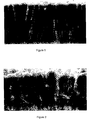
- Figures 1 and 2 show Scanning Electron Microscope (SEM) cross-section micrographs at 8000X magnification of an ⁇ -alumina layer according to the present invention, Figure 1, and an Al 2 O 3 -layer according to prior art technique, Figure 2.
- Figure 1 displays the characteristic columnar microstructure and
- Figure 2 displays a more coarse-grained microstructure typical of prior art.
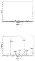
- Figures 3 and 4 show X-ray diffraction patterns for ⁇ -Al 2 O 3 layers deposited according to the invention, Figure 3, and according to prior art technique, Figure 4.
- FIGS 5 and 6 show Light Optical Microscope (LOM) micrographs of worn cutting edges of a coated cutting insert according to present the invention, Figure 5, and according to prior art, Figure 6.
- LOM Light Optical Microscope
- the cutting edges of the tool obtain a smooth surface finish, which compared to prior art ⁇ -Al 2 O 3 coated tools, results in an improved surface finish also of the workpiece being machined.
- the invented ⁇ -Al 2 O 3 layer may also contain a low concentration of residues of a "texture modifying agent" which may be present in the form of separate grains or in the form of a solid solution with the alumina grains.
- concentration of said residues can be found in the range 0.01-10, preferably 0.01-5 and most preferably less than 1 percent by weight of the ⁇ -alumina coating and the amount of said residues is low enough not to affect the intrinsic properties of the alumina coating itself.
- the ⁇ -Al 2 O 3 layer according to the present invention exhibits a preferred crystal growth orientation in the [300]-direction which is determined by X-ray Diffraction (XRD) measurements.
- Figures 3 and 4 show X-ray diffraction patterns for ⁇ -Al 2 O 3 layers deposited according to the invention ( Figure 3) and according to prior art technique ( Figure 4). The very pronounced growth orientation in the [300]-direction is easily perceived from Figure 3.
- TC for the set of (300)-crystalplanes is larger than 1.5, preferably larger than 3 and most preferably larger than 5.
- the applied coating on the cutting tool may in addition to the strongly textured ⁇ -Al 2 O 3 layer(s) contain at least one layer comprising a carbide, nitride, carbonitride, oxycarbide and/or oxycarbonitride of the metal elements (Me 1 , Me 2 , ...) selected from the groups IVB, VB and VIB of the Periodic Table or from the group B, Al and Si and/or mixtures thereof, (Me 1 , Me 2 , ...)C x N y O z , TiC X N y O z being preferred.
- a carbide, nitride, carbonitride, oxycarbide and/or oxycarbonitride of the metal elements (Me 1 , Me 2 , ...) selected from the groups IVB, VB and VIB of the Periodic Table or from the group B, Al and Si and/or mixtures thereof, (Me 1 , Me 2 , ...)C x N y O z , Ti
- the ⁇ -Al 2 O 3 layer according to the present invention is preferably the outermost layer of the coating and the TiC x N y O z layer is the innermost layer of the coating.
- metal-C x N y O z layers may also be deposited on top of the alfa-alumina layer(s).
- the outer layer on top of the outermost ⁇ -Al 2 O 3 layer is TiN.
- the textured ⁇ -Al 2 O 3 layer according to the invention is deposited by a CVD (Chemical Vapor Deposition) technique where the tool substrates to be coated are held at a temperature 950-1050 °C and are brought in contact with a hydrogen carrier gas containing one or more halides of aluminium, and a hydrolysing and/or an oxidizing agent.
- the oxidation potential of the CVD reactor atmosphere prior to the nucleation of Al 2 O 3 is kept at a low level with a concentration of water vapor (H 2 O) or other oxidizing species such as CO 2 , O 2 , etc., below 5 ppm.
- the nucleation of ⁇ -Al 2 O 3 is started up by sequencing of the reactant gases that HCl and CO 2 are entering the reactor first in an Ar and/or H 2 atmosphere followed by AlCl 3 .
- a sulphur catalyst preferably H 2 S, is added to the reaction gas mixture in order to obtain the enhanced deposition rate.
- a crystallographic structure is attained having a very strong texture in the [300]-direction.
- concentration of a second halide, a so-called texture modifying agent, preferably ZrCl 4 shall be in the range of 0.05-10, preferably 0.2-5 and most preferably 0.5-2 percent by volume of the total reaction gas volume.
- the invented CVD method described above has made it possible to deposit ⁇ -Al 2 O 3 layers with a desired micro structure and orientation and, said layers can be grown to a relatively large thickness, and surprisingly, still retain their excellent adhesion properties to the tool substrate as well as adding the desired improvement in wear resistance of the cutting tool which will demonstrated in a forthcoming example.
- the surface may also be smoothened by a standard brushing technique.
- Coated tool inserts from A) and B) were brushed using a standard production method in order to smoothen the coating surface.
- the cutting inserts were then tested with respect to edge line and rake face flaking in a turning operation, facing in nodular cast iron (AISI 60-40-18, DIN GGG40), a machining test which has proven to be a good benchmark test on the strength of the coating adhesion.
- AISI 60-40-18, DIN GGG40 nodular cast iron
- Figures 5 and 6 show Light Optical Microscope (LOM) micrographs of worn cutting edges tested according to the above described method.
- Figure 5 shows the wear pattern of a coated cutting insert according to present the invention and
- Figure 6 shows the wear pattern of coated cutting insert according to prior art technique.
- LOM Light Optical Microscope
Abstract
Description
- The present invention describes a cutting tool for metal machining, having a substrate of cemented carbide, cermet or ceramics and on the surface of said substrate, a hard and wear resistant coating is deposited. The coating is adherently bonded to the substrate and covering all functional parts of the tool. The coating is composed of one or more refractory layers of which at least one layer consists of strongly textured alfa-alumina (α-Al2O3).
- It is well known that for cemented carbide cutting tools used in metal machining, the wear resistance of the tool edge considerably can be increased by applying thin, hard surface layers of metal oxides, carbides or nitrides with the metal either selected from the transition metals from the groups IV, V and VI of the Periodic Table or from the group silicon, boron and aluminium. The coating thickness usually varies between 1 and 15 µm and the most widespread method for depositing such coatings is CVD (Chemical Vapor Deposition).
- The practice of applying a pure ceramic layer such as alumina on top of layers of metal carbides and nitrides for further improvements of the performance of a cutting tool was early recognized as is evidenced in Re 29,420 (Lindström et al) and US 3,836,392 (Lux et al). Alumina coated cutting tools are further disclosed in US 4,180,400 (Smith et al), US 4,619,866 (Smith et al), US 5,071,696 (Chatfield et al), US 5,674,564 (Ljungberg et al) and US 5,137,774 (Ruppi) wherein the Al2O3 layers comprise the α- and κ-phases and/or combinations thereof. For example, in US 4,180,400, an alumina deposition process is disclosed where tetravalent ions of e.g. Ti, Zr or Hf are added in their halide compositions to the reaction gas mixture in order to deposit essentially single phase κ-Al2O3.
- The practice of mixing different metal halides in order to deposit composite ceramic coatings is evidenced in US 4,701,384 (Sarin et al), US 4,745,010 (Sarin et al) and US 5,827,570 (Russell) where processes for depositing mixtures of e.g. Al2O3 and ZrO2 are described.
- In further efforts to improve the cutting performance of alumina coated cemented carbide cutting tools, particularly in the machining of nodular cast iron, deposition processes yielding fine-grained, single phase α-Al2O3 exhibiting specific crystal orientation (texture) and surface finish are disclosed in US 5,654,035 (Ljungberg et al), US 5,766,782 (Ljungberg), US 5,834,061 (Ljungberg) and US 5,980,988 (Ljungberg).
- None the less the machining of nodular cast iron is still considered to be a demanding metal working operation. This is particularly obvious in heavy and interrupted machining operations where an α-Al2O3 coated tool often suffers from extensive flaking of the alumina layer from the tool substrate. Hence, it is the object of the present invention to provide onto a hard tool substrate a relatively thick Al2O3-layer of the polymorph alpha with a desired microstructure and crystallographic texture by applying a deposition process with suitable nucleation and growth conditions such that the acquired properties of the Al2O3-layer provide an alumina coated cutting tool with improved cutting performance in steel, stainless steel, cast iron and, in particular, in nodular cast iron.
- According to the present invention there is provided a cutting tool for metal machining such as turning (threading and parting), milling and drilling comprising a body of a hard alloy of sintered cemented carbide, cermet or ceramic onto which a hard and wear resistant refractory coating is deposited. Said coating comprises a structure of one or several refractory layers of which at least one layer consists of alumina with a layer thickness of 0.5-25 µm, preferably 1-10 µm. The alumina layer consists of essentially single phase α-alumina with a pronounced columnar grain-structure.
- Figures 1 and 2 show Scanning Electron Microscope (SEM) cross-section micrographs at 8000X magnification of an α-alumina layer according to the present invention, Figure 1, and an Al2O3-layer according to prior art technique, Figure 2. Figure 1 displays the characteristic columnar microstructure and Figure 2 displays a more coarse-grained microstructure typical of prior art.
- Figures 3 and 4 show X-ray diffraction patterns for α-Al2O3 layers deposited according to the invention, Figure 3, and according to prior art technique, Figure 4.
- Figures 5 and 6 show Light Optical Microscope (LOM) micrographs of worn cutting edges of a coated cutting insert according to present the invention, Figure 5, and according to prior art, Figure 6.
- As a consequence of the fine-grained structure perpendicular to the growth direction of the α-alumina layer according to the invention, the cutting edges of the tool obtain a smooth surface finish, which compared to prior art α-Al2O3 coated tools, results in an improved surface finish also of the workpiece being machined.
- The invented α-Al2O3 layer may also contain a low concentration of residues of a "texture modifying agent" which may be present in the form of separate grains or in the form of a solid solution with the alumina grains. The concentration of said residues can be found in the range 0.01-10, preferably 0.01-5 and most preferably less than 1 percent by weight of the α-alumina coating and the amount of said residues is low enough not to affect the intrinsic properties of the alumina coating itself.
- The α-Al2O3 layer according to the present invention exhibits a preferred crystal growth orientation in the [300]-direction which is determined by X-ray Diffraction (XRD) measurements. Figures 3 and 4 show X-ray diffraction patterns for α-Al2O3 layers deposited according to the invention (Figure 3) and according to prior art technique (Figure 4). The very pronounced growth orientation in the [300]-direction is easily perceived from Figure 3.
- A Texture Coefficient, TC, can be defined as:
- I(hkl) = measured intensity of the (hkl) reflection.
- Io(hkl) = standard intensity of the ASTM standard powder pattern diffraction data card number 43-1484.
- n = number of reflections used in the calculation, (hkl)reflections used are: (012), (104), (110), (113), (024), (116), (300).
-
- According to the present invention, TC for the set of (300)-crystalplanes is larger than 1.5, preferably larger than 3 and most preferably larger than 5.
- The applied coating on the cutting tool may in addition to the strongly textured α-Al2O3 layer(s) contain at least one layer comprising a carbide, nitride, carbonitride, oxycarbide and/or oxycarbonitride of the metal elements (Me1, Me2, ...) selected from the groups IVB, VB and VIB of the Periodic Table or from the group B, Al and Si and/or mixtures thereof, (Me1, Me2, ...)CxNyOz, TiCXNyOz being preferred. In a preferred embodiment the α-Al2O3 layer according to the present invention is preferably the outermost layer of the coating and the TiCxNyOz layer is the innermost layer of the coating. But metal-CxNyOz layers may also be deposited on top of the alfa-alumina layer(s). In a preferred embodiment the outer layer on top of the outermost α-Al2O3 layer is TiN.
- The textured α-Al2O3 layer according to the invention is deposited by a CVD (Chemical Vapor Deposition) technique where the tool substrates to be coated are held at a temperature 950-1050 °C and are brought in contact with a hydrogen carrier gas containing one or more halides of aluminium, and a hydrolysing and/or an oxidizing agent. The oxidation potential of the CVD reactor atmosphere prior to the nucleation of Al2O3 is kept at a low level with a concentration of water vapor (H2O) or other oxidizing species such as CO2, O2, etc., below 5 ppm. The nucleation of α-Al2O3 is started up by sequencing of the reactant gases that HCl and CO2 are entering the reactor first in an Ar and/or H2 atmosphere followed by AlCl3. When nucleation of α-Al2O3 has occurred, a sulphur catalyst, preferably H2S, is added to the reaction gas mixture in order to obtain the enhanced deposition rate.
- Surprisingly, it has been found that when adding small amounts ZrCl4 to the reaction gas mixture during the growth period of the α-Al2O3 layer, a crystallographic structure is attained having a very strong texture in the [300]-direction. The concentration of a second halide, a so-called texture modifying agent, preferably ZrCl4, shall be in the range of 0.05-10, preferably 0.2-5 and most preferably 0.5-2 percent by volume of the total reaction gas volume.
- The invented CVD method described above has made it possible to deposit α-Al2O3 layers with a desired micro structure and orientation and, said layers can be grown to a relatively large thickness, and surprisingly, still retain their excellent adhesion properties to the tool substrate as well as adding the desired improvement in wear resistance of the cutting tool which will demonstrated in a forthcoming example. In order to further improve the properties of the coated cutting tool the surface may also be smoothened by a standard brushing technique.
- The exact conditions of the CVD process depend to a certain extent upon the design of the equipment being used. It is within the purview of the person skilled in the art to determine whether the requisite texture and coating morphology have been obtained and to modify the nucleation and deposition conditions in accordance with the present specification, if desired, to affect the degree of texture and coating morphology.
-
- A) Cemented carbide cutting inserts with the composition 6.0
weight-% Co, and balance WC were coated with a 3 µm thick layer of
TiCN in a standard CVD process. In subsequent process steps during
the same coating cycle, a 7 µm thick layer of α-Al2O3 was deposited
by the method described below.
A reaction gas mixture comprising H2, HCl and CO2 was first
introduced into the CVD-reactor. The reaction gases were sequentially
added in the given order. After a pre-set time AlCl3 was
allowed into the reactor. During the deposition of Al2O3, H2S was
used as a catalyst and ZrCl4 as texture modifying agent. The gas
mixtures and other process conditions during the Al2O3 deposition
steps comprised:
Step 1. Step 2.CO2 5% 5% AlCl 32% 2% ZrCl4 - 1% H2S - 0.3% HCl 2% 6% H2 Balance Balance Pressure 55 mbar 55 mbar Temperature 1010°C 1010°C Duration 1 hour 3 hours - B) Cemented carbide substrate of A) was coated with TiCN (3
µm) and Al2O3 (7 µm) as set forth in A) except that the Al2O3
deposition process was carried out according to prior art technique.
The gas mixtures and other process conditions during the
Al2O3 deposition steps comprised:
Step 1. Step 2.CO2 5% 5% AlCl 32% 2% ZrCl4 - - H2S - 0.3% HCl 2% 6% H2 Balance Balance Pressure 55 mbar 55 mbar Temperature 1010°C 1010°C Duration 1 hour 3 hours -
- Coated tool inserts from A) and B) were brushed using a standard production method in order to smoothen the coating surface. The cutting inserts were then tested with respect to edge line and rake face flaking in a turning operation, facing in nodular cast iron (AISI 60-40-18, DIN GGG40), a machining test which has proven to be a good benchmark test on the strength of the coating adhesion.

- The results are expressed in the table below as percentage of the edge line in cut on which flaking of the coating has occurred, and furthermore, the rake face area subjected to flaking in relation to the total contact area between the rake face and the workpiece chip. The numbers shown in the table below are average values for five tested cutting edges.
Coating Edge line flaking Rake face flaking According to A 4% <1% According to B 53% 62% - Figures 5 and 6 show Light Optical Microscope (LOM) micrographs of worn cutting edges tested according to the above described method. Figure 5 shows the wear pattern of a coated cutting insert according to present the invention and Figure 6 shows the wear pattern of coated cutting insert according to prior art technique.
Claims (8)
- Cutting tool comprising a body of sintered cemented carbide, cermet or ceramic and on which at least on the functional parts of the surface of the body, a hard and wear resistant coating is applied and said coating comprising a structure of one or more refractory layers of which at least one layer consists of alumina characterised in that said alumina layer having a thickness of 0.5-25 µm, preferably 1-10 µm, and consisting of essentially single phase α-alumina textured in the [300]-direction with a texture coefficient larger than 1.5, preferably larger than 3, and most preferably larger than 5, the texture coefficient being defined as:I(hkl) = measured intensity of the (hkl) reflectionIo(hkl) = standard intensity of the ASTM standard powder pattern diffraction data, card number 43-1484.n = number of reflections used in the calculation (hkl) reflections used are: (012), (104), (110), (113), (024), (116) and (300).
- Cutting tool according to claim 1 characterised in that said α-alumina layer contains between 0.01-10, preferably 0.01-5 and most preferably less than 1 percent by weight of residues of a texture modifying agent.
- Cutting tool according to any of the preceding claims characterised in having at least one layer of thickness 0.1-10 µm, preferably 0.5-5 µm, comprising a nitride, carbide, carbonitride, oxycarbide and/or oxycarbonitride of the metal titanium (TiCxNyOz) and that said layer is in contact with the α-alumina layer.
- Cutting tool according to claim 3 characterised in that the outer layer is α-alumina.
- Cutting tool according to any of the preceding claims characterised in that the outer layer is TiN.
- Cutting tool according to any of the preceding claims characterised in that the surface of the coated cutting tool is smoothened by means of a brushing operation.
- A method for producing a coated cutting tool, wherein at least one refractory layer consisting of α-alumina textured in the [300]-direction as per claim; 1, is deposited by CVD (Chemical Vapor Deposition) by which the tool surface to be coated is brought in contact with a hydrogen carrier gas containing one or more halides of aluminium and a hydrolysing and/or an oxidizing agent characterised in that the oxidation potential of the CVD-reactor atmosphere prior to the nucleation of α-alumina is kept at a low level with a concentration of water vapor (H2O) or other oxidizing species preferably below 5 ppm, and that the nucleation of α-alumina is started up by the sequencing of the reactant gases that HCl and CO2 are entering the reactor first in an H2 and/or Ar atmosphere followed by AlC13, that the temperature is held at 950-1050°C during the nucleation period, that during the growth period of the α-Al2O3 layer a sulphur catalyst and a texture modifying agent are added, the catalyst preferably being H2S and the texture modifying agent preferably being ZrCl4.
- A method according to claim 7 characterised in that the addition of a texture modifying agent, preferably ZrCl4 to the reaction gas mixture shall be in the range of 0.05-10, preferably 0.2-5 and most preferably 0.5-2 percent by volume of the total reaction gas mixture.
Applications Claiming Priority (2)
| Application Number | Priority Date | Filing Date | Title |
|---|---|---|---|
| SE0100520 | 2001-02-16 | ||
| SE0100520A SE522736C2 (en) | 2001-02-16 | 2001-02-16 | Aluminum-coated cutting tool and method for making the same |
Publications (3)
| Publication Number | Publication Date |
|---|---|
| EP1247789A2 true EP1247789A2 (en) | 2002-10-09 |
| EP1247789A3 EP1247789A3 (en) | 2004-03-31 |
| EP1247789B1 EP1247789B1 (en) | 2008-04-09 |
Family
ID=20283011
Family Applications (1)
| Application Number | Title | Priority Date | Filing Date |
|---|---|---|---|
| EP02003026A Expired - Lifetime EP1247789B1 (en) | 2001-02-16 | 2002-02-12 | Alpha-alumina coated cutting tool |
Country Status (6)
| Country | Link |
|---|---|
| US (2) | US6869668B2 (en) |
| EP (1) | EP1247789B1 (en) |
| JP (1) | JP4312989B2 (en) |
| AT (1) | ATE391704T1 (en) |
| DE (1) | DE60225965T2 (en) |
| SE (1) | SE522736C2 (en) |
Cited By (11)
| Publication number | Priority date | Publication date | Assignee | Title |
|---|---|---|---|---|
| EP1477581A1 (en) * | 2003-05-10 | 2004-11-17 | Seco Tools Ab | Enhanced alumina layer produced by CVD |
| EP1528125A2 (en) * | 2003-10-27 | 2005-05-04 | Seco Tools Ab | Coated cutting insert for rough turning |
| EP1536041A2 (en) * | 2003-11-25 | 2005-06-01 | Mitsubishi Materials Corporation | Coated cermet cutting tool with a chipping resistant, hard coating layer |
| WO2006072288A2 (en) * | 2004-12-30 | 2006-07-13 | Walter Ag | Al2o3 multilayer plate |
| US7094447B2 (en) | 2002-05-08 | 2006-08-22 | Seco Tools Ab | Enhanced alumina layer produced by CVD |
| EP1772217A1 (en) * | 2004-07-29 | 2007-04-11 | Kyocera Corporation | Surface coated cutting tool |
| US7273665B2 (en) * | 2003-12-22 | 2007-09-25 | Mitsubishi Materials Corporation | Surface-coated cermet cutting tool with hard coating layer having excellent chipping resistance |
| US7531212B2 (en) * | 2002-08-08 | 2009-05-12 | Kobe Steel, Ltd. | Process for producing an alumina coating comprised mainly of α crystal structure |
| US8318293B2 (en) | 2005-06-17 | 2012-11-27 | Sandvik Intellectual Property Ab | Coated cutting tool insert |
| WO2017057456A1 (en) * | 2015-09-28 | 2017-04-06 | 京セラ株式会社 | Coated tool |
| EP1817442B1 (en) * | 2004-12-02 | 2019-03-06 | CERATIZIT Austria Gesellschaft m.b.H. | Machining tool |
Families Citing this family (52)
| Publication number | Priority date | Publication date | Assignee | Title |
|---|---|---|---|---|
| SE526526C3 (en) * | 2003-04-01 | 2005-10-26 | Sandvik Intellectual Property | Ways of coating cutting with A1203 and a cutting tool with A1203 |
| JP4512989B2 (en) * | 2003-12-26 | 2010-07-28 | 三菱マテリアル株式会社 | Surface coated cermet cutting tool with excellent chipping resistance with hard coating layer |
| SE528430C2 (en) * | 2004-11-05 | 2006-11-14 | Seco Tools Ab | With aluminum oxide coated cutting tool inserts and method of making this |
| SE528432C2 (en) | 2004-11-05 | 2006-11-14 | Seco Tools Ab | With aluminum oxide coated cutting tool inserts and method for making this |
| SE528431C2 (en) * | 2004-11-05 | 2006-11-14 | Seco Tools Ab | With aluminum oxide coated cutting tool inserts and method of making this |
| JP4518260B2 (en) * | 2005-01-21 | 2010-08-04 | 三菱マテリアル株式会社 | Surface-coated cermet cutting tool whose hard coating layer exhibits excellent chipping resistance in high-speed intermittent cutting |
| JP4747386B2 (en) * | 2005-04-15 | 2011-08-17 | 三菱マテリアル株式会社 | Surface coated cermet cutting tool whose hard coating layer exhibits excellent wear resistance in high speed cutting |
| JP4747387B2 (en) * | 2005-06-07 | 2011-08-17 | 三菱マテリアル株式会社 | Surface-coated cermet cutting tool with excellent chipping resistance thanks to thick α-type aluminum oxide layer |
| SE529051C2 (en) * | 2005-09-27 | 2007-04-17 | Seco Tools Ab | Cutting tool inserts coated with alumina |
| JP4816904B2 (en) * | 2005-12-22 | 2011-11-16 | 三菱マテリアル株式会社 | Surface coated cermet cutting tool whose hard coating layer exhibits excellent wear resistance in high speed cutting |
| SE532023C2 (en) * | 2007-02-01 | 2009-09-29 | Seco Tools Ab | Textured hardened alpha-alumina coated cutting for metalworking |
| SE531670C2 (en) | 2007-02-01 | 2009-06-30 | Seco Tools Ab | Textured alpha-alumina coated cutting for metalworking |
| SE531929C2 (en) | 2007-07-13 | 2009-09-08 | Seco Tools Ab | Coated cemented carbide inserts for turning steel or stainless steel |
| US8080323B2 (en) * | 2007-06-28 | 2011-12-20 | Kennametal Inc. | Cutting insert with a wear-resistant coating scheme exhibiting wear indication and method of making the same |
| US20090004449A1 (en) * | 2007-06-28 | 2009-01-01 | Zhigang Ban | Cutting insert with a wear-resistant coating scheme exhibiting wear indication and method of making the same |
| JP4836202B2 (en) * | 2007-07-20 | 2011-12-14 | 日立ツール株式会社 | Coated tool |
| JP5187570B2 (en) * | 2007-12-28 | 2013-04-24 | 三菱マテリアル株式会社 | Surface coated cutting tool with excellent wear resistance due to hard coating layer |
| SE532050C2 (en) * | 2008-03-07 | 2009-10-13 | Seco Tools Ab | Oxide coated cutting tool cutter for chip separating machining of steel |
| SE532047C2 (en) | 2008-03-07 | 2009-10-13 | Seco Tools Ab | Oxide coated cutting tool cutter for chip separating machining of cast iron |
| SE532049C2 (en) | 2008-03-07 | 2009-10-13 | Seco Tools Ab | Oxide coated cutting tool cutter for chip separating machining of steel |
| SE532048C2 (en) * | 2008-03-07 | 2009-10-13 | Seco Tools Ab | Oxide coated cutting tool cutter for chip separating machining of steel |
| JP5229683B2 (en) * | 2008-03-18 | 2013-07-03 | 日立ツール株式会社 | Coated tool |
| JP5187571B2 (en) * | 2008-06-20 | 2013-04-24 | 三菱マテリアル株式会社 | Surface coated cutting tool with excellent wear resistance due to hard coating layer |
| JP5739086B2 (en) * | 2008-11-04 | 2015-06-24 | 三菱マテリアル株式会社 | Surface coated cutting tool with excellent chipping resistance due to hard coating layer |
| US8828527B2 (en) | 2009-03-18 | 2014-09-09 | Mitsubishi Materials Corporation | Surface-coated cutting tool |
| JP5424097B2 (en) * | 2009-06-22 | 2014-02-26 | 三菱マテリアル株式会社 | Surface coated cutting tool with excellent chipping resistance due to hard coating layer |
| JP5428569B2 (en) * | 2009-06-24 | 2014-02-26 | 三菱マテリアル株式会社 | Surface coated cutting tool with excellent chipping resistance due to hard coating layer |
| EP2363509A1 (en) * | 2010-02-28 | 2011-09-07 | Oerlikon Trading AG, Trübbach | Synthesis of metal oxides by reactive cathodic arc evaporation |
| EP2395126A1 (en) | 2010-06-08 | 2011-12-14 | Seco Tools AB | Textured alumina layer |
| EP2446988A1 (en) | 2010-10-29 | 2012-05-02 | Seco Tools AB | Cutting tool insert with an alpha-alumina layer having a multi-components texture |
| WO2012079769A1 (en) | 2010-12-17 | 2012-06-21 | Seco Tools Ab | Coated cubic boron nitride tool for machining applications |
| CN103205728B (en) * | 2012-01-17 | 2015-04-08 | 株洲钻石切削刀具股份有限公司 | Surface-modified coated cutting tool and preparation method thereof |
| US9138864B2 (en) | 2013-01-25 | 2015-09-22 | Kennametal Inc. | Green colored refractory coatings for cutting tools |
| US9017809B2 (en) | 2013-01-25 | 2015-04-28 | Kennametal Inc. | Coatings for cutting tools |
| US9371580B2 (en) | 2013-03-21 | 2016-06-21 | Kennametal Inc. | Coated body wherein the coating scheme includes a coating layer of TiAl2O3 and method of making the same |
| US9181620B2 (en) | 2013-03-21 | 2015-11-10 | Kennametal Inc. | Coatings for cutting tools |
| WO2014153440A1 (en) | 2013-03-21 | 2014-09-25 | Kennametal Inc. | Coatings for cutting tools |
| CN105579171B (en) * | 2013-08-21 | 2017-12-01 | 株式会社泰珂洛 | Coated cutting tool |
| EP2902528B1 (en) | 2014-01-30 | 2016-06-29 | Walter Ag | Alumina coated cutting tool with zigzag alumina grain boundaries |
| US10286453B2 (en) | 2014-01-30 | 2019-05-14 | Sandvik Intellectual Property Ab | Alumina coated cutting tool |
| US9719175B2 (en) | 2014-09-30 | 2017-08-01 | Kennametal Inc. | Multilayer structured coatings for cutting tools |
| US9650712B2 (en) | 2014-12-08 | 2017-05-16 | Kennametal Inc. | Inter-anchored multilayer refractory coatings |
| US9650714B2 (en) | 2014-12-08 | 2017-05-16 | Kennametal Inc. | Nanocomposite refractory coatings and applications thereof |
| EP3263743A1 (en) * | 2016-06-29 | 2018-01-03 | Sandvik Intellectual Property AB | Cvd coated cutting tool |
| JP6635340B2 (en) * | 2016-08-24 | 2020-01-22 | 住友電工ハードメタル株式会社 | Surface coated cutting tool and method of manufacturing the same |
| JP6999585B2 (en) * | 2019-01-18 | 2022-01-18 | 株式会社タンガロイ | Cover cutting tool |
| JP7060528B2 (en) * | 2019-01-18 | 2022-04-26 | 株式会社タンガロイ | Cover cutting tool |
| JP7055761B2 (en) * | 2019-02-15 | 2022-04-18 | 株式会社タンガロイ | Cover cutting tool |
| JP6876278B2 (en) * | 2019-05-14 | 2021-05-26 | 株式会社タンガロイ | Cover cutting tool |
| EP3848485A1 (en) | 2020-01-10 | 2021-07-14 | Sakari Ruppi | Improved alpha alumina layer deposited with controlled textures |
| EP3848484A3 (en) | 2020-01-10 | 2021-09-15 | Sakari Ruppi | Improved alumina layer deposited at low temperature |
| CN114875379B (en) * | 2022-04-29 | 2023-09-29 | 厦门金鹭特种合金有限公司 | Alumina composite coating, preparation method thereof and cutting device |
Citations (3)
| Publication number | Priority date | Publication date | Assignee | Title |
|---|---|---|---|---|
| US5654035A (en) * | 1992-12-18 | 1997-08-05 | Sandvik Ab | Method of coating a body with an α-alumina coating |
| EP0999293A1 (en) * | 1998-11-05 | 2000-05-10 | Hitachi Metals, Ltd. | Aluminium oxide-coated article |
| JP2001038504A (en) * | 1999-08-02 | 2001-02-13 | Mitsubishi Materials Corp | Surface coated cemented carbide cutting tool with hard coating layer exercising superior chipping resistance during highly efficient cutting |
Family Cites Families (14)
| Publication number | Priority date | Publication date | Assignee | Title |
|---|---|---|---|---|
| CH540990A (en) | 1971-07-07 | 1973-08-31 | Battelle Memorial Institute | Method for increasing the wear resistance of the surface of a cutting tool |
| USRE29420E (en) | 1971-11-12 | 1977-09-27 | Sandvik Aktiebolag | Sintered cemented carbide body coated with two layers |
| SE406090B (en) | 1977-06-09 | 1979-01-22 | Sandvik Ab | COATED HARD METAL BODY AND WAY TO PRODUCE A SUITABLE BODY |
| US4619866A (en) | 1980-07-28 | 1986-10-28 | Santrade Limited | Method of making a coated cemented carbide body and resulting body |
| US4745010A (en) | 1987-01-20 | 1988-05-17 | Gte Laboratories Incorporated | Process for depositing a composite ceramic coating on a cemented carbide substrate |
| US4701384A (en) | 1987-01-20 | 1987-10-20 | Gte Laboratories Incorporated | Composite coatings on cemented carbide substrates |
| US4702970A (en) * | 1987-01-20 | 1987-10-27 | Gte Laboratories Incorporated | Composite coatings on ceramic substrates |
| SE464818B (en) | 1989-06-16 | 1991-06-17 | Sandvik Ab | COVERED SHOULD BE CUTTING |
| EP0408535B1 (en) | 1989-07-13 | 1994-04-06 | Seco Tools Ab | Multi-oxide coated carbide body and method of producing the same |
| SE502174C2 (en) | 1993-12-23 | 1995-09-04 | Sandvik Ab | Methods and articles when coating a cutting tool with an alumina layer |
| SE502223C2 (en) | 1994-01-14 | 1995-09-18 | Sandvik Ab | Methods and articles when coating a cutting tool with an alumina layer |
| CA2149567C (en) | 1994-05-31 | 2000-12-05 | William C. Russell | Coated cutting tool and method of making same |
| SE504968C2 (en) * | 1994-11-15 | 1997-06-02 | Sandvik Ab | Method of coating a cutting tool with a layer of alpha-Al2O3 |
| SE514177C2 (en) * | 1995-07-14 | 2001-01-15 | Sandvik Ab | Coated cemented carbide inserts for intermittent machining in low alloy steel |
-
2001
- 2001-02-16 SE SE0100520A patent/SE522736C2/en not_active IP Right Cessation
-
2002
- 2002-02-12 EP EP02003026A patent/EP1247789B1/en not_active Expired - Lifetime
- 2002-02-12 AT AT02003026T patent/ATE391704T1/en active
- 2002-02-12 DE DE60225965T patent/DE60225965T2/en not_active Expired - Lifetime
- 2002-02-13 US US10/073,239 patent/US6869668B2/en not_active Expired - Lifetime
- 2002-02-18 JP JP2002040230A patent/JP4312989B2/en not_active Expired - Fee Related
-
2004
- 2004-04-14 US US10/823,661 patent/US7011867B2/en not_active Expired - Fee Related
Patent Citations (3)
| Publication number | Priority date | Publication date | Assignee | Title |
|---|---|---|---|---|
| US5654035A (en) * | 1992-12-18 | 1997-08-05 | Sandvik Ab | Method of coating a body with an α-alumina coating |
| EP0999293A1 (en) * | 1998-11-05 | 2000-05-10 | Hitachi Metals, Ltd. | Aluminium oxide-coated article |
| JP2001038504A (en) * | 1999-08-02 | 2001-02-13 | Mitsubishi Materials Corp | Surface coated cemented carbide cutting tool with hard coating layer exercising superior chipping resistance during highly efficient cutting |
Non-Patent Citations (2)
| Title |
|---|
| LUX B ET AL: "Preparation of alumina coatings by chemical vapour deposition" THIN SOLID FILMS, 1 APRIL 1986, SWITZERLAND, vol. 138, no. 1, pages 49-64, XP002266696 ISSN: 0040-6090 * |
| PATENT ABSTRACTS OF JAPAN vol. 2000, no. 19, 5 June 2001 (2001-06-05) -& JP 2001 038504 A (MITSUBISHI MATERIALS CORP), 13 February 2001 (2001-02-13) * |
Cited By (22)
| Publication number | Priority date | Publication date | Assignee | Title |
|---|---|---|---|---|
| US7163735B2 (en) | 2002-05-08 | 2007-01-16 | Seco Tools Ab | Enhanced alumina layer produced by CVD |
| US7396581B2 (en) | 2002-05-08 | 2008-07-08 | Seco Tools Ab | Enhanced alumina layer produced by CVD |
| US7094447B2 (en) | 2002-05-08 | 2006-08-22 | Seco Tools Ab | Enhanced alumina layer produced by CVD |
| US7531212B2 (en) * | 2002-08-08 | 2009-05-12 | Kobe Steel, Ltd. | Process for producing an alumina coating comprised mainly of α crystal structure |
| EP1477581A1 (en) * | 2003-05-10 | 2004-11-17 | Seco Tools Ab | Enhanced alumina layer produced by CVD |
| US7135221B2 (en) | 2003-10-27 | 2006-11-14 | Seco Tools Ab | Coated cutting insert for rough turning |
| EP1528125A2 (en) * | 2003-10-27 | 2005-05-04 | Seco Tools Ab | Coated cutting insert for rough turning |
| CZ305063B6 (en) * | 2003-10-27 | 2015-04-22 | Seco Tools Ab | Cutting tool insert with protective layer for rough turning |
| EP1528125A3 (en) * | 2003-10-27 | 2006-01-25 | Seco Tools Ab | Coated cutting insert for rough turning |
| CN100445000C (en) * | 2003-10-27 | 2008-12-24 | 山高刀具公司 | Coated cutting insert for rough turning |
| EP1536041A3 (en) * | 2003-11-25 | 2006-03-29 | Mitsubishi Materials Corporation | Coated cermet cutting tool with a chipping resistant, hard coating layer |
| US7276301B2 (en) | 2003-11-25 | 2007-10-02 | Mitsubishi Materials Corporation | Surface-coated cermet cutting tool with a hard coating layer exhibiting excellent chipping resistance |
| EP1536041A2 (en) * | 2003-11-25 | 2005-06-01 | Mitsubishi Materials Corporation | Coated cermet cutting tool with a chipping resistant, hard coating layer |
| CN100445023C (en) * | 2003-12-22 | 2008-12-24 | 三菱综合材料株式会社 | Surface-coated cermet cutting tool with hard coating layer having excellend chipping resistance |
| US7273665B2 (en) * | 2003-12-22 | 2007-09-25 | Mitsubishi Materials Corporation | Surface-coated cermet cutting tool with hard coating layer having excellent chipping resistance |
| EP1772217A1 (en) * | 2004-07-29 | 2007-04-11 | Kyocera Corporation | Surface coated cutting tool |
| EP1772217A4 (en) * | 2004-07-29 | 2011-12-28 | Kyocera Corp | Surface coated cutting tool |
| EP1817442B1 (en) * | 2004-12-02 | 2019-03-06 | CERATIZIT Austria Gesellschaft m.b.H. | Machining tool |
| WO2006072288A3 (en) * | 2004-12-30 | 2006-10-19 | Walter Ag | Al2o3 multilayer plate |
| WO2006072288A2 (en) * | 2004-12-30 | 2006-07-13 | Walter Ag | Al2o3 multilayer plate |
| US8318293B2 (en) | 2005-06-17 | 2012-11-27 | Sandvik Intellectual Property Ab | Coated cutting tool insert |
| WO2017057456A1 (en) * | 2015-09-28 | 2017-04-06 | 京セラ株式会社 | Coated tool |
Also Published As
| Publication number | Publication date |
|---|---|
| ATE391704T1 (en) | 2008-04-15 |
| US20040202877A1 (en) | 2004-10-14 |
| DE60225965T2 (en) | 2009-05-20 |
| SE522736C2 (en) | 2004-03-02 |
| US6869668B2 (en) | 2005-03-22 |
| JP2002263914A (en) | 2002-09-17 |
| JP4312989B2 (en) | 2009-08-12 |
| EP1247789A3 (en) | 2004-03-31 |
| DE60225965D1 (en) | 2008-05-21 |
| SE0100520L (en) | 2002-08-17 |
| US20020155325A1 (en) | 2002-10-24 |
| US7011867B2 (en) | 2006-03-14 |
| EP1247789B1 (en) | 2008-04-09 |
| SE0100520D0 (en) | 2001-02-16 |
Similar Documents
| Publication | Publication Date | Title |
|---|---|---|
| EP1247789B1 (en) | Alpha-alumina coated cutting tool | |
| US6713172B2 (en) | Oxide coated cutting tool | |
| EP0738336B1 (en) | Oxide coated cutting tool | |
| US5654035A (en) | Method of coating a body with an α-alumina coating | |
| US6673430B2 (en) | PVD Al2O3 coated cutting tool | |
| EP0659903B1 (en) | Alumina coated cutting tool | |
| US7993742B2 (en) | Alumina layer with enhanced texture | |
| EP0753602B1 (en) | Oxide coated cutting tool | |
| US5702808A (en) | Al2 O2 -coated cutting tool preferably for near net shape machining | |
| EP1262576B1 (en) | CVD Al2O3 coated cutting tool | |
| EP1477581A1 (en) | Enhanced alumina layer produced by CVD |
Legal Events
| Date | Code | Title | Description |
|---|---|---|---|
| PUAI | Public reference made under article 153(3) epc to a published international application that has entered the european phase |
Free format text: ORIGINAL CODE: 0009012 |
|
| AK | Designated contracting states |
Kind code of ref document: A2 Designated state(s): AT BE CH CY DE DK ES FI FR GB GR IE IT LI LU MC NL PT SE TR |
|
| AX | Request for extension of the european patent |
Free format text: AL;LT;LV;MK;RO;SI |
|
| PUAL | Search report despatched |
Free format text: ORIGINAL CODE: 0009013 |
|
| RIC1 | Information provided on ipc code assigned before grant |
Ipc: 7C 04B 41/87 A Ipc: 7C 23C 16/40 B Ipc: 7C 04B 41/89 B |
|
| AK | Designated contracting states |
Kind code of ref document: A3 Designated state(s): AT BE CH CY DE DK ES FI FR GB GR IE IT LI LU MC NL PT SE TR |
|
| AX | Request for extension of the european patent |
Extension state: AL LT LV MK RO SI |
|
| 17P | Request for examination filed |
Effective date: 20040927 |
|
| 17Q | First examination report despatched |
Effective date: 20041026 |
|
| AKX | Designation fees paid |
Designated state(s): AT BE CH CY DE DK ES FI FR GB GR IE IT LI LU MC NL PT SE TR |
|
| RAP1 | Party data changed (applicant data changed or rights of an application transferred) |
Owner name: SANDVIK INTELLECTUAL PROPERTY HB |
|
| RAP1 | Party data changed (applicant data changed or rights of an application transferred) |
Owner name: SANDVIK INTELLECTUAL PROPERTY AB |
|
| GRAP | Despatch of communication of intention to grant a patent |
Free format text: ORIGINAL CODE: EPIDOSNIGR1 |
|
| GRAS | Grant fee paid |
Free format text: ORIGINAL CODE: EPIDOSNIGR3 |
|
| GRAL | Information related to payment of fee for publishing/printing deleted |
Free format text: ORIGINAL CODE: EPIDOSDIGR3 |
|
| GRAS | Grant fee paid |
Free format text: ORIGINAL CODE: EPIDOSNIGR3 |
|
| GRAA | (expected) grant |
Free format text: ORIGINAL CODE: 0009210 |
|
| AK | Designated contracting states |
Kind code of ref document: B1 Designated state(s): AT BE CH CY DE DK ES FI FR GB GR IE IT LI LU MC NL PT SE TR |
|
| REG | Reference to a national code |
Ref country code: GB Ref legal event code: FG4D |
|
| REG | Reference to a national code |
Ref country code: CH Ref legal event code: EP |
|
| REG | Reference to a national code |
Ref country code: IE Ref legal event code: FG4D |
|
| REF | Corresponds to: |
Ref document number: 60225965 Country of ref document: DE Date of ref document: 20080521 Kind code of ref document: P |
|
| REG | Reference to a national code |
Ref country code: CH Ref legal event code: NV Representative=s name: BOVARD AG PATENTANWAELTE |
|
| REG | Reference to a national code |
Ref country code: SE Ref legal event code: TRGR |
|
| NLV1 | Nl: lapsed or annulled due to failure to fulfill the requirements of art. 29p and 29m of the patents act | ||
| PG25 | Lapsed in a contracting state [announced via postgrant information from national office to epo] |
Ref country code: FI Free format text: LAPSE BECAUSE OF FAILURE TO SUBMIT A TRANSLATION OF THE DESCRIPTION OR TO PAY THE FEE WITHIN THE PRESCRIBED TIME-LIMIT Effective date: 20080409 Ref country code: PT Free format text: LAPSE BECAUSE OF FAILURE TO SUBMIT A TRANSLATION OF THE DESCRIPTION OR TO PAY THE FEE WITHIN THE PRESCRIBED TIME-LIMIT Effective date: 20080909 Ref country code: ES Free format text: LAPSE BECAUSE OF FAILURE TO SUBMIT A TRANSLATION OF THE DESCRIPTION OR TO PAY THE FEE WITHIN THE PRESCRIBED TIME-LIMIT Effective date: 20080720 Ref country code: NL Free format text: LAPSE BECAUSE OF FAILURE TO SUBMIT A TRANSLATION OF THE DESCRIPTION OR TO PAY THE FEE WITHIN THE PRESCRIBED TIME-LIMIT Effective date: 20080409 |
|
| ET | Fr: translation filed | ||
| PG25 | Lapsed in a contracting state [announced via postgrant information from national office to epo] |
Ref country code: DK Free format text: LAPSE BECAUSE OF FAILURE TO SUBMIT A TRANSLATION OF THE DESCRIPTION OR TO PAY THE FEE WITHIN THE PRESCRIBED TIME-LIMIT Effective date: 20080409 |
|
| PLBE | No opposition filed within time limit |
Free format text: ORIGINAL CODE: 0009261 |
|
| STAA | Information on the status of an ep patent application or granted ep patent |
Free format text: STATUS: NO OPPOSITION FILED WITHIN TIME LIMIT |
|
| PG25 | Lapsed in a contracting state [announced via postgrant information from national office to epo] |
Ref country code: BE Free format text: LAPSE BECAUSE OF FAILURE TO SUBMIT A TRANSLATION OF THE DESCRIPTION OR TO PAY THE FEE WITHIN THE PRESCRIBED TIME-LIMIT Effective date: 20080409 |
|
| 26N | No opposition filed |
Effective date: 20090112 |
|
| PG25 | Lapsed in a contracting state [announced via postgrant information from national office to epo] |
Ref country code: MC Free format text: LAPSE BECAUSE OF NON-PAYMENT OF DUE FEES Effective date: 20090228 Ref country code: CY Free format text: LAPSE BECAUSE OF FAILURE TO SUBMIT A TRANSLATION OF THE DESCRIPTION OR TO PAY THE FEE WITHIN THE PRESCRIBED TIME-LIMIT Effective date: 20080409 |
|
| PG25 | Lapsed in a contracting state [announced via postgrant information from national office to epo] |
Ref country code: IE Free format text: LAPSE BECAUSE OF NON-PAYMENT OF DUE FEES Effective date: 20090212 |
|
| PG25 | Lapsed in a contracting state [announced via postgrant information from national office to epo] |
Ref country code: GR Free format text: LAPSE BECAUSE OF FAILURE TO SUBMIT A TRANSLATION OF THE DESCRIPTION OR TO PAY THE FEE WITHIN THE PRESCRIBED TIME-LIMIT Effective date: 20080710 |
|
| REG | Reference to a national code |
Ref country code: CH Ref legal event code: PFA Owner name: SANDVIK INTELLECTUAL PROPERTY AB Free format text: SANDVIK INTELLECTUAL PROPERTY AB# #811 81 SANDVIKEN (SE) -TRANSFER TO- SANDVIK INTELLECTUAL PROPERTY AB# #811 81 SANDVIKEN (SE) |
|
| PG25 | Lapsed in a contracting state [announced via postgrant information from national office to epo] |
Ref country code: LU Free format text: LAPSE BECAUSE OF NON-PAYMENT OF DUE FEES Effective date: 20090212 |
|
| PG25 | Lapsed in a contracting state [announced via postgrant information from national office to epo] |
Ref country code: TR Free format text: LAPSE BECAUSE OF FAILURE TO SUBMIT A TRANSLATION OF THE DESCRIPTION OR TO PAY THE FEE WITHIN THE PRESCRIBED TIME-LIMIT Effective date: 20080409 |
|
| PGFP | Annual fee paid to national office [announced via postgrant information from national office to epo] |
Ref country code: SE Payment date: 20150212 Year of fee payment: 14 |
|
| REG | Reference to a national code |
Ref country code: FR Ref legal event code: PLFP Year of fee payment: 15 |
|
| REG | Reference to a national code |
Ref country code: SE Ref legal event code: EUG |
|
| PG25 | Lapsed in a contracting state [announced via postgrant information from national office to epo] |
Ref country code: SE Free format text: LAPSE BECAUSE OF NON-PAYMENT OF DUE FEES Effective date: 20160213 |
|
| REG | Reference to a national code |
Ref country code: FR Ref legal event code: PLFP Year of fee payment: 16 |
|
| PGFP | Annual fee paid to national office [announced via postgrant information from national office to epo] |
Ref country code: DE Payment date: 20170207 Year of fee payment: 16 Ref country code: FR Payment date: 20170112 Year of fee payment: 16 Ref country code: CH Payment date: 20170214 Year of fee payment: 16 |
|
| PGFP | Annual fee paid to national office [announced via postgrant information from national office to epo] |
Ref country code: GB Payment date: 20170208 Year of fee payment: 16 Ref country code: AT Payment date: 20170125 Year of fee payment: 16 |
|
| PGFP | Annual fee paid to national office [announced via postgrant information from national office to epo] |
Ref country code: IT Payment date: 20170221 Year of fee payment: 16 |
|
| REG | Reference to a national code |
Ref country code: DE Ref legal event code: R119 Ref document number: 60225965 Country of ref document: DE |
|
| REG | Reference to a national code |
Ref country code: CH Ref legal event code: PL |
|
| REG | Reference to a national code |
Ref country code: AT Ref legal event code: MM01 Ref document number: 391704 Country of ref document: AT Kind code of ref document: T Effective date: 20180212 |
|
| GBPC | Gb: european patent ceased through non-payment of renewal fee |
Effective date: 20180212 |
|
| PG25 | Lapsed in a contracting state [announced via postgrant information from national office to epo] |
Ref country code: CH Free format text: LAPSE BECAUSE OF NON-PAYMENT OF DUE FEES Effective date: 20180228 Ref country code: AT Free format text: LAPSE BECAUSE OF NON-PAYMENT OF DUE FEES Effective date: 20180212 Ref country code: LI Free format text: LAPSE BECAUSE OF NON-PAYMENT OF DUE FEES Effective date: 20180228 |
|
| REG | Reference to a national code |
Ref country code: FR Ref legal event code: ST Effective date: 20181031 |
|
| PG25 | Lapsed in a contracting state [announced via postgrant information from national office to epo] |
Ref country code: DE Free format text: LAPSE BECAUSE OF NON-PAYMENT OF DUE FEES Effective date: 20180901 |
|
| PG25 | Lapsed in a contracting state [announced via postgrant information from national office to epo] |
Ref country code: GB Free format text: LAPSE BECAUSE OF NON-PAYMENT OF DUE FEES Effective date: 20180212 Ref country code: IT Free format text: LAPSE BECAUSE OF NON-PAYMENT OF DUE FEES Effective date: 20180212 Ref country code: FR Free format text: LAPSE BECAUSE OF NON-PAYMENT OF DUE FEES Effective date: 20180228 |