EP1248568B1 - Surgical screw delivery system - Google Patents
Surgical screw delivery system Download PDFInfo
- Publication number
- EP1248568B1 EP1248568B1 EP00992245A EP00992245A EP1248568B1 EP 1248568 B1 EP1248568 B1 EP 1248568B1 EP 00992245 A EP00992245 A EP 00992245A EP 00992245 A EP00992245 A EP 00992245A EP 1248568 B1 EP1248568 B1 EP 1248568B1
- Authority
- EP
- European Patent Office
- Prior art keywords
- stop
- exterior surface
- length
- screw
- bone
- Prior art date
- Legal status (The legal status is an assumption and is not a legal conclusion. Google has not performed a legal analysis and makes no representation as to the accuracy of the status listed.)
- Expired - Lifetime
Links
Images


Classifications
-
- A—HUMAN NECESSITIES
- A61—MEDICAL OR VETERINARY SCIENCE; HYGIENE
- A61B—DIAGNOSIS; SURGERY; IDENTIFICATION
- A61B17/00—Surgical instruments, devices or methods, e.g. tourniquets
- A61B17/56—Surgical instruments or methods for treatment of bones or joints; Devices specially adapted therefor
- A61B17/58—Surgical instruments or methods for treatment of bones or joints; Devices specially adapted therefor for osteosynthesis, e.g. bone plates, screws, setting implements or the like
- A61B17/88—Osteosynthesis instruments; Methods or means for implanting or extracting internal or external fixation devices
- A61B17/8863—Apparatus for shaping or cutting osteosynthesis equipment by medical personnel
-
- A—HUMAN NECESSITIES
- A61—MEDICAL OR VETERINARY SCIENCE; HYGIENE
- A61B—DIAGNOSIS; SURGERY; IDENTIFICATION
- A61B17/00—Surgical instruments, devices or methods, e.g. tourniquets
- A61B17/16—Bone cutting, breaking or removal means other than saws, e.g. Osteoclasts; Drills or chisels for bones; Trepans
- A61B17/1662—Bone cutting, breaking or removal means other than saws, e.g. Osteoclasts; Drills or chisels for bones; Trepans for particular parts of the body
- A61B17/1671—Bone cutting, breaking or removal means other than saws, e.g. Osteoclasts; Drills or chisels for bones; Trepans for particular parts of the body for the spine
-
- A—HUMAN NECESSITIES
- A61—MEDICAL OR VETERINARY SCIENCE; HYGIENE
- A61B—DIAGNOSIS; SURGERY; IDENTIFICATION
- A61B17/00—Surgical instruments, devices or methods, e.g. tourniquets
- A61B17/16—Bone cutting, breaking or removal means other than saws, e.g. Osteoclasts; Drills or chisels for bones; Trepans
- A61B17/17—Guides or aligning means for drills, mills, pins or wires
- A61B17/1735—Guides or aligning means for drills, mills, pins or wires for rasps or chisels
-
- A—HUMAN NECESSITIES
- A61—MEDICAL OR VETERINARY SCIENCE; HYGIENE
- A61B—DIAGNOSIS; SURGERY; IDENTIFICATION
- A61B17/00—Surgical instruments, devices or methods, e.g. tourniquets
- A61B17/16—Bone cutting, breaking or removal means other than saws, e.g. Osteoclasts; Drills or chisels for bones; Trepans
- A61B17/1613—Component parts
- A61B17/1615—Drill bits, i.e. rotating tools extending from a handpiece to contact the worked material
-
- A—HUMAN NECESSITIES
- A61—MEDICAL OR VETERINARY SCIENCE; HYGIENE
- A61B—DIAGNOSIS; SURGERY; IDENTIFICATION
- A61B17/00—Surgical instruments, devices or methods, e.g. tourniquets
- A61B17/16—Bone cutting, breaking or removal means other than saws, e.g. Osteoclasts; Drills or chisels for bones; Trepans
- A61B17/1655—Bone cutting, breaking or removal means other than saws, e.g. Osteoclasts; Drills or chisels for bones; Trepans for tapping
-
- A—HUMAN NECESSITIES
- A61—MEDICAL OR VETERINARY SCIENCE; HYGIENE
- A61B—DIAGNOSIS; SURGERY; IDENTIFICATION
- A61B17/00—Surgical instruments, devices or methods, e.g. tourniquets
- A61B17/16—Bone cutting, breaking or removal means other than saws, e.g. Osteoclasts; Drills or chisels for bones; Trepans
- A61B17/17—Guides or aligning means for drills, mills, pins or wires
- A61B17/1739—Guides or aligning means for drills, mills, pins or wires specially adapted for particular parts of the body
- A61B17/1757—Guides or aligning means for drills, mills, pins or wires specially adapted for particular parts of the body for the spine
-
- A—HUMAN NECESSITIES
- A61—MEDICAL OR VETERINARY SCIENCE; HYGIENE
- A61B—DIAGNOSIS; SURGERY; IDENTIFICATION
- A61B17/00—Surgical instruments, devices or methods, e.g. tourniquets
- A61B17/56—Surgical instruments or methods for treatment of bones or joints; Devices specially adapted therefor
- A61B17/58—Surgical instruments or methods for treatment of bones or joints; Devices specially adapted therefor for osteosynthesis, e.g. bone plates, screws, setting implements or the like
- A61B17/88—Osteosynthesis instruments; Methods or means for implanting or extracting internal or external fixation devices
- A61B17/8875—Screwdrivers, spanners or wrenches
-
- A—HUMAN NECESSITIES
- A61—MEDICAL OR VETERINARY SCIENCE; HYGIENE
- A61B—DIAGNOSIS; SURGERY; IDENTIFICATION
- A61B17/00—Surgical instruments, devices or methods, e.g. tourniquets
- A61B2017/0042—Surgical instruments, devices or methods, e.g. tourniquets with special provisions for gripping
- A61B2017/00424—Surgical instruments, devices or methods, e.g. tourniquets with special provisions for gripping ergonomic, e.g. fitting in fist
-
- A—HUMAN NECESSITIES
- A61—MEDICAL OR VETERINARY SCIENCE; HYGIENE
- A61B—DIAGNOSIS; SURGERY; IDENTIFICATION
- A61B90/00—Instruments, implements or accessories specially adapted for surgery or diagnosis and not covered by any of the groups A61B1/00 - A61B50/00, e.g. for luxation treatment or for protecting wound edges
- A61B90/03—Automatic limiting or abutting means, e.g. for safety
- A61B2090/033—Abutting means, stops, e.g. abutting on tissue or skin
- A61B2090/034—Abutting means, stops, e.g. abutting on tissue or skin abutting on parts of the device itself
Definitions
- the human spine is a flexible weight bearing column formed from a plurality of bones called vertebrae.
- vertebrae There are 33 vertebrae which are named based on which of five regions (cervical, dorsal, lumbar, sacral, and coccygeal) in which they are found. Going from the top of the spine down, in general there are seven cervical vertebra, twelve dorsal vertebra, five lumbar vertebra, five sacral vertebra, and four coccygeal vertebra.
- each vertebra contains an anterior, solid segment or body and a posterior segment or arch.
- the arch is generally formed of two pedicles and two laminae, supporting seven processes -- four articular, two transverse, and one spinous.
- the first cervical vertebra (atlas vertebra) has neither a body nor spinous process.
- the second cervical vertebra (axis vertebra) has an odontoid process, which is a strong, prominent process, shaped like a tooth, rising perpendicularly from the upper surface of the body of the axis vertebra. Further details regarding the construction of the spine are known to those of ordinary skill in the art and may be found in such common references as Gray's Anatomy , Crown Publishers, Inc., 1977, pp. 33-54.
- Implant devices include a variety of longitudinal elements such as rods or plates which span two or more vertebra and are affixed to the vertebra by various fixation elements such as wires, staples, and screws (often inserted through the pedicles of the vertebra). These systems may be affixed to either the posterior or the anterior side of the spine. In many cases, these implant systems are prominent beneath the skin and have a higher profile than more simple fixation devices.
- One such simpler fixation device is in the stable posterior fusion of the atlas and axis vertebra by transarticular screw fixation using the technique of Magerl et al.
- transarticular screw fixation in both fusion procedures and stabilization procedures for fractures has undergone increasing use.
- procedures making use of transarticular screw fixation have required extremely long and wide midline incisions in order to place the screws as necessary in various procedures in both the cervical and lumbar spine regions.
- These large incisions result in increased operating time with consequent increase in blood loss as well as enlarging the size of the scar left on the patient.
- the size of the incision and the scar it leaves behind are often the only visible measure a patient will have to judge the quality of the surgeon's work.
- the incision is made in a manner not only to preserve the skin's contour, but of a minimum length and size to increase patient satisfaction.
- the present invention provides a screw delivery system kit providing a minimally invasive portal with a small entry angle to a surgical site, comprising an outer cannula, a trocar, a guide and a bone drill bit.
- the outer cannula has a first exterior surface and a first interior surface defining a bore.
- the first interior surface has a first inner diameter and the first exterior surface has a first outer diameter.
- the surfaces extend along a first length on a first axis between a first proximal end having a first stop and a first distal end.
- the trocar has a second exterior surface with a second outer diameter.
- the second exterior surface extends along a second length on a second axis between a second proximal end having a second stop defined thereon and a second distal end defining a blunt tip.
- the guide has a handle and a tube.
- the tube has a third exterior surface and a third interior surface defining a passageway.
- the third interior surface has a third inner diameter and the third exterior surface has a third outer diameter.
- the third interior surface extends between a third proximal end and a third distal end.
- the third exterior surface extends along a third length on a third axis between a third stop at the third proximal end and the third distal end.
- the handle is connected to the tube at an angle to the third axis.
- the bone drill bit has a fourth exterior surface with a fourth outer diameter extending along a fourth length on a fourth axis between a fourth stop located near a fourth proximal end and a plurality of drilling flutes defined on a fourth
- outer cannula 100 extending along longitudinal axis 101.
- Outer cannula 100 provides the primary passageway for screw implantation to a surgical site through a percutaneous portal (as discussed further below) distant from the surgical site.
- Many of the spinal surgeries for which the screw delivery system of the present invention will find use in involve very small entrance angles for the screw with respect to the spine of a patient lying prone.
- the outer cannula 100 has a bore 101a extending between the near end 102 and far end 104 of the outer cannula 100.
- Outer cannula 100 has an exterior surface 106 and an interior surface 108, interior surface 108 defining bore 101a.
- the far end 104 of outer cannula 100 terminates in a tip 110.
- Tip 110 is shown as having serrations with a crescent moon-like shape for ease of contacting the surgical site (i.e., bone of a vertebra). It should be understood, however, that the tip 110 may take a variety of shapes and forms other than the crescent moon illustrated.
- the near end 102 of outer cannula 100 has an annular flange or stop 112. Bore 101a also extends through the annular flange 112.
- the stop 112 acts in combination with the stops on other devices inserted through the bore 101a of the outer cannula to prevent over-insertion of the various bone drill bits, taps, and other probes and interventional devices and prevents possible damage to the surgical site resulting from over-insertion. It should be understood that stop 112 need not be in the shape of an annular flange, but may simply be a plurality of projections extending from the exterior surface 108 of outer cannula 100.
- outer cannula 100 may also be simply the circumference of the exterior surface 108 of outer cannula 100 at the near end 102. This is because the stops of the other probes or interventional devices (e.g., bone drill bits, bone taps, guides) will contact the circumference of the near end 102 of the exterior surface 106 of outer cannula 100. It should also be understood that the preferred embodiment is for outer cannula 100 to possess an annular flange 112. Outer cannula 100 has an inner diameter D1 for bore 101 a and an outer diameter D2 as illustrated in Fig. 1.
- Trocar 120 extending along a longitudinal axis 121 between a proximal end 122 and a distal end 124.
- Trocar 120 is preferably, but not necessarily, a solid shaft having an exterior surface 126 between the proximal end 122 and the distal end 124.
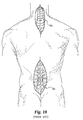
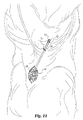
- the distal end 124 of trocar 120 has a bullet-shaped head 130 with a blunt tip 131 for minimizing the trauma to the tissue as the combination of the trocar 120 and the outer cannula 100 are used as a soft tissue penetrator or introducer from a distal incision 50 on the back to the surgical site 55 of the vertebra (see Fig. 11).
- Trocar 120 has an annular flange or stop 132 at the proximal end 122.
- the exterior surface 126 of trocar 120 has an outer diameter D3.
- the outer diameter D3 of trocar 120 is less than the inner diameter D1 of outer cannula 100 which is in turn less than the outer diameter D2 of outer cannula 100. Since the outer diameter D3 is less than the inner diameter D1, the exterior surface 126 of trocar 120 may be inserted through the bore 101a of outer cannula 100.
- the trocar 120 need merely have an unbroken surface at bullet-shaped head 130 and whatever other portion extends beyond the far end 104 of outer cannula 100.
- Fig. 2 illustrates trocar 120 as a solid shaft, variations as would occur to a person of ordinary skill in the art for the connection between the distal end 124 and the proximal end 122 of trocar 120 are contemplated as within the scope of the claims.
- the trocar 120 has a length such that when inserted through the bore 101a of outer cannula 100, the bullet-shaped head 130 will extend past the tip 110 of outer cannula 100.
- the front face 132a of the annular flange 132 will contact the rear face 112b of stop 112 of outer cannula 100 (see Fig. 11).
- the bullet-shaped head 130 will extend past the tip 110 of outer cannula 100 thus permitting the trocar 120 and outer cannula 100 to be percutaneously inserted through an incision 50 distal from the surgical site 55.
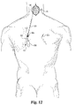
- FIG. 11 demonstrates the applicability of the soft tissue penetrator combination of trocar 120 with outer cannula 100 in the lumbar vertebra of the spine, the screw delivery system of the present invention is equally useful for avoiding the necessity of a large midline incision when a surgical site is, for example, in a cervical vertebra as is the case in a transarticular screw fixation across the atlanto-axial joint (see Fig. 12).
- the devices used through the bore 101a of outer cannula 100 in various embodiments of the present invention are illustrated in Figs. 3-9 and are discussed in more detail below. After the details of the individual components of various embodiments of the present invention are outlined, the method of their use will be discussed in further detail. With reference to Fig. 3, there is illustrated one embodiment of a device for more accurately aiming various embodiments of bone drill bits and bone taps to the appropriate lengths.
- the guide 140 generally extends along a longitudinal axis 141 (with the exception of the handle 158).
- the guide 140 has a bore 141a defined by an interior surface 148 extending between the proximal end 142 and the distal end 144.
- the guide 140 has an exterior surface 146 defined between the proximal end 142 and the distal end 144 which terminates in a tip 150.
- the proximal end 142 of the guide 140 has an annular flange or stop 152 with a front face 156 and a rear face 157.
- the exterior surface 146 has an outer diameter D5 and the interior surface 148 has an inner diameter D4.
- the guide 140 has a handle 158 which is connected at an angle to the stop 152. It should be understood, however, that the handle 158 may be located/connected at a variety of locations.
- the handle 158 is at an angle transverse to the longitudinal axis 141. The angle of the handle is relevant to many of the applications with small entry angles as it should not be perpendicular to the longitudinal axis 141. It should also be understood that the angle that the handle 158 makes with respect to the longitudinal axis 141 is preferably less than 60 degrees.
- the outer diameter D5 is greater than the inner diameter D4, but is less than the inner diameter D1 of the outer cannula 100.
- the exterior surface 146 may be inserted through the bore 101a of outer cannula 100 until the front face 156 of guide 140 contacts the rear face 112b of stop 112 of outer cannula 100.
- various other instruments are inserted through the bore 141a as well as the bore 101a such as the bone drill bits 160, 180, and tap 200 discussed below.
- a side view of a standard bone drill bit 160 extending along an axis 161 between a proximal end 162 and a drilling end 164.
- the proximal end 162 has a surface adapted for the application of force to rotate the bone drill bit 160.
- the standard bone drill bit 160 has a half solid cylinder 163a and a flattened portion 163b at the proximal end 162 to permit rotation of the standard bone drill bit 160.
- the drilling end 164 has a plurality of flutes 165 and a standard drill tip 170.
- Standard bone drill bit 160 has an exterior surface 166 extending between the front face 172a of annular flange or stop 172 and the beginning of the flutes 165 making up the drilling end 164 of standard bone drill 160.
- the exterior surface 166 of standard bone drill bit 160 has an outer diameter D6. Additionally, the portion of exterior surface 166 near annular flange or stop 172 preferably has a plurality of length markings 167.
- a bone drill bit 180 for use in the screw delivery system of the present invention. It should be understood that due to the small entry angle between the bone drill bit and the bone in the spine/vertebra of the surgical site, that a standard bone drill bit 160 has a blunt end that is difficult to get started. The tip 170 of the bone drill bit 160 has a tendency to walk along the surface, making accurate placement difficult. Thus, the more preferred embodiment is bone drill bit 180 which extends along an axis 181 between a proximal end 182 and drilling end 184.
- the preferred bone drill 180 has a half solid cylinder 183a and a flattened portion 183b at proximal end 182 for use in rotating the bone drill bit 180.
- the drilling end 184 of bone drill bit 180 has a plurality of flutes 185.
- Bone drill bit 180 has an exterior surface 186 extending between the front face 192a of annular flange or stop 192 and the beginning of the plurality of flutes 185 on the drilling end 184.
- Bone drill bit 180 has a sharper angled drill tip 190 at the end of drilling end 184 which permits ease of insertion when beginning to drill even at the small entry angles preferably less than 45° (not perpendicular to bone) for the methods of use of the screw delivery system discussed further below.
- the exterior surface 186 of bone drill bit 180 has an outer diameter D7. Both outer diameter D7 and outer diameter D6 are less than the inner diameter D4 of guide 140.
- the guide 140 has an inner diameter D4 which is only slightly larger than the outer diameter D6 or outer diameter D7 of bone drills 160, 180, respectively. This permits more accurate placement of the drill tips 170, 190 and minimizes deviations from side to side of the axis 161, 181, respectively when drilling.
- Bone tap 200 extends along axis 201 between proximal end 202 and tapping end 204. Similar to the bone drill bits 160, 180, the proximal end 202 of tap 200 has a solid half cylinder 203a and a flattened portion 203b to permit rotation of the bone tap 200. As is understood by those of ordinary skill in the art, the tapping end 204 of bone tap 200 has threading 205 thereon and a tip 210 for creating threading in the opening or bore in the bone created by a bone drill bit 160, 180.
- Bone tap 200 has an exterior surface 206 extending between the front surface 212a of annular flange or stop 212 and the beginning of the threading 205 at the tapping end 204.
- the exterior surface 206 has an outer diameter D8 which is less than the inner diameter D4 of the guide 140 to permit the bone tap 200 to be inserted through the bore 141a of guide 140.
- the exterior surface 206 of bone tap 200 preferably has a plurality of length markings 207 on the portion of exterior surface 206 adjacent the annular flange or stop 212.
- cutter 220 has handles 222, 223 which are pivotally connected around hinge 224.
- the cutting end 226 of cutter 220 is made up of a first cutting element 230 and a second cutting element 235.
- the first cutting element 230 has a first sharp edge 231 adjacent a circular depression 232 which has its own cutting edge 233.
- second cutting element 235 has a second sharp edge 236 adjacent another circular depression 237 having its own cutting edge 238. It should be understood that cutter 220 is intended for use on the adjustable length stop 240 as illustrated in Fig. 8.
- the adjustable length stop 240 has integrally connected individual cylindrical elements 242 with a length L and an inner diameter D9 and an outer diameter D10.
- the individual cylindrical elements 242 of adjustable length stop 240 extend along a longitudinal axis 241.
- the individual cylindrical elements 242 of the adjustable length stop 240 define a bore 248 extending along the axis 241.
- the length L of the individual cylindrical elements 242 corresponds to the distance between the length markings such as length markings 207 on bone tap 200, length markings 187 on bone drill bit 180, and/or length markings 167 on bone drill bit 160.
- the length of the individual cylindrical elements may be different than that of the markings on the respective bone drill bits and taps, and that the length of each individual cylindrical element may vary on a single adjustable length stop 240. It should be understood that the inner diameter D9 of bore 248 of the adjustable length stop 240 should be greater than diameters D8, D7, D6, but is less than D5 which in turn is less than D1 which is less than D2.
- the outer diameter D10 should be greater than either the outer diameter D5 of the guide 140 or at least of a sufficient diameter so that the adjustable length stop 240 will act as a contact mechanism to prevent further insertion of the bone drills or bone taps upon contacting the rear face 157 of annular flange or stop 152 of the guide 140.
- the outer diameter D10 should be such that the adjustable length stop 240 will contact the rear surface 112b of annular flange or stop 102 of outer cannula 100.
- Screwdriver 260 extends generally along axis 261 between a proximal end 262 and distal end 264.
- Screwdriver 260 comprises a handle 278 which has a front face 276. Front face 276 of handle 278 could act as a stop, but in general the length of the screwdriver 260 is made deliberately long so that whatever screw used may be screwed in as deep as may be deemed necessary.
- Screwdriver 260 has an exterior surface 266 with an outer diameter D1 extending between the front face 276 of handle 278 and the tip 270 at distal end 264.
- the tip 270 of screw driver 260 is configured so as to fit within the screw head of the screw used for transarticular screw fixation and other surgeries as contemplated within the scope of the invention.
- the tip 270 of screwdriver 260 will define a polygonal shape which will mate with a polygonal socket of the same shape in the screw head of the screw used.
- the screw delivery system of the present invention is particularly useful for three primary surgical indications.
- the first indication is use in repair of a odontoid fracture.
- the second indication is transarticular screw fixation across the first and second cervical vertebrae.
- the third indication is transarticular screw fixation across the lumbar facet joint. All of these indications will be discussed with more specificity below.
- the general procedure essentially entails seizing the joint between the vertebrae and immobilizing it until either the fracture heals (as in the first indication) or until fusion occurs (as in the second or third indications). It should be understood that the first indication is an anterior procedure while the second and third indications are posterior procedures.
- the soft tissue penetrator or introducer in the form of the outer cannula 100 with the trocar 120 having a bullet-shaped head 130 is introduced through an incision 50 in the skin on the back and directed toward the surgical site (in Fig. 11 the surgical site is across lumbar vertebra) viewed through incision 55.
- the tip 110 of the outer cannula 100 is then seated on the portion of the bone or vertebra at the appropriate angle for the introduction of the screw for fixation.
- the bullet-shaped head 130, and indeed the entire trocar 120, are then removed from the outer cannula 100.
- the distal end 144 of the drill guide 140 is inserted through the near end 102 of outer cannula 100 until the front face 156 of stop 152 of guide 140 contacts the rear face 112b of annular flange or stop 112 of outer cannula 100.
- the drilling end 184 of bone drill bit 180 is inserted through the bore 141 a of guide 140 past the distal end 144 and then on into the bore 101a of outer cannula 100. It should be understood that the surgeon could use a high speed burr to mark the point of insertion of the screw, but this generally weakens the fixation of the screw's strength because of the loss of cortical bone on the outside surface of the vertebra.
- the improved drill bit 180 of the present invention which has a sharper angled drill tip 190 which permits easier insertion during the beginning of the drilling process despite the very small entry angle commonly encountered in transarticular screw fixation across vertebral joints.
- the bone drill bit 180 has a plurality of length markings 187 adjacent the annular flange or stop 192.
- the length markings 187 allow the surgeon to know the distance the drill has been drilled into the bone at a glance by examining the length markings 187 of the bone drill bit 180.
- the screws (not shown) to be used are of a fixed length which can be measured.
- an adjustable length stop 240 is inserted onto either the bone drill bit 180 or tap 200 as appropriate.
- the exterior surface 186, 206 of the bone drill bit 180 or tap 200, respectively, is inserted through the bore 248 of the adjustable length stop 240.
- both the bone tap 200 and the bone drill bit 180 will be marked with 30 mil projections in 5mm increments.
- the length L of the individual cylindrical elements 142 of the adjustable length stop 140 will generally be equal to these 5mm increments of the length markings 207 and 187.
- the adjustable length stop 240 is simple and does not change the lengths of the guide 140 permitting the use of one standard guide 140 and of standard length bone drill bits 180 and bone taps 200.
- the variable is the adjustable length stop 240, which is generally constructed of plastic, allowing the use of a cutter 220 to trim the total length of the adjustable length stop 240, thus permitting the desired length of insertion of the bone drill bit 180 and bone tap 200.
- the cutter 220 may either cut off individual cylindrical elements 242 to alter the length L of adjustable length stop 240 or may even be used to cut through an individual cylindrical element 242. It should be understood that it is generally preferable if the cutter 220 is used to cut to total length the adjustable length stop 240 by trimming through the weakened portion between the individual cylindrical elements which is intended to break off.
- the bone drill bit 180 is inserted through the bore 141a of the guide 140 and the bore 101a of the concentric outer cannula 100 and the drill is rotated and an opening in the bone is created by advancing the bone drill bit 180 along axis 181 until the adjustable length stop 240 contacts the rear face 157 of stop 152 of the guide 140 which prevents further advancement of the bone drill bit 180 into the bone.
- the bone drill bit 180 is then removed from both the guide 140 and outer cannula 100.
- the bone tap 200 is introduced through the bores 141a and 101a.
- the bone tap 200 will have an adjustable length stop 240 of the same total length as that used on the guide 140.
- the opening in the bone created by the bone drill bit 180 is then threaded by rotating and advancing bone tap 200 until the adjustable length stop 240 on bone tap 200 contacts the rear face 157 of stop 152 on guide 140.
- the entire inner sleeve in the form of the bone tap 200 and guide 140 is removed from the outer cannula 100.
- a screw and implant driver are introduced through the near end 102 of outer cannula 100.
- the implant driver will generally be a standard screwdriver 260 having a tip 270 with a polygonal head which will mate with a same shaped polygonal socket in the head of the screw (not shown) to be driven into the bone.
- the screw and screwdriver 260 are inserted through the bore 101a of outer cannula 100 until they have reached the opening located beyond the tip 110 of the far end 104 of outer cannula 100. The location of this opening will vary depending on the indication as described further below.
- the first indication of particular use for the screw delivery system and method of the present invention is for use with an odontoid fracture.
- An odontoid fracture is a special type of C2 (second cervical vertebra) or axis vertebra.
- the odontoid is a prominent process, tooth-like in form, projecting perpendicularly upward from the axis vertebra toward the atlas vertebra.
- odontoid fractures were treated by the use of halo.
- the alternative treatment mechanism is to insert a screw across the fracture site. This will be an anterior procedure through the neck, so that operating through the bore 101a of the outer cannula 100 aids in protecting important structures in the neck as well as providing a minimally invasive procedure generally.
- Odontoid screw fixation is a technically demanding procedure that requires thorough preoperative planning and adequate surgical training.
- the entry point is critical at the anterior margin of the inferior endplate. If started more cephalad, the angle of inclination for fracture fixation cannot be achieved and anterior gapping of the fracture is a common result. Also, poor proximal fragment purchase with subsequent screw cut-out may occur. It is important to engage the far cortex of the odontoid tip to ensure adequate purchase and it is mandatory to lag the fracture fragments either through screw design or by creating a gliding hole through the body fragment. AP and lateral fluoroscopy is essential for constant monitoring during all stages of this procedure.
- Odontoid screw fixation using the screw delivery system of the present invention is a combination of percutaneous and open technique to make a minimally invasive approach.
- the surgeon actually views the entry site of the screw and through a separate incision places the screw delivery system while viewing where the far end 104 of the outer cannula 100 is going to dock.
- the technique is generally done using biplanar fluoroscopy, which allows viewing of the fracture on TV screens as you place the drill, tap and screw, respectively, across it during the procedure.
- the entirety of drilling, tapping, and screw insertion is done through the working sleeve in the form of the outer cannula 100 and drill guide 140, as previously discussed.
- the articles describing the standard technique recommend making an incision from C1 all the way down to C7 (see incision 65a of Fig. 10).
- the use of the screw delivery system and method of the present invention requires only a small midline incision 65 (see Fig. 12) at the C1/C2 region and two percutaneous incisions 60a and 60b (see Fig. 12) around the upper thoracic area through which the screw delivery system of the present invention is introduced and directed toward the surgical site at the joint between C1 and C2. This surgical site is viewed directly through the small midline incision 65 made.
- the third indication mentioned above as deriving particular benefit through use of the screw delivery system of the present invention is placing a screw across a lumbar facet joint to fuse the joint between two lumbar vertebra. This may be done rather than putting pedicle screws in and then attaching those anchors (the pedicle screws) to a rod, plate or other longitudinal element spanning the intervertebral disc or the space left behind after it is excised. Instead, in this procedure, the surgeon simply places two screws in the shape of an X (when viewed from above a prone patient) across the lumbar facet joint. This is usually done in combination with an anterior interbody fusion which has more recently undergone an upsurge in popularity with the use of devices known as cages.
- the benefits of simply putting screws across the lumbar facet joint as to the more complex apparatus involving insertion of pedicle screws and attaching longitudinal elements to the anchors is that putting screws across the lumbar facet joint results in a very, very low profile implant.
- this third indication is a minimally invasive procedure which is a combination of percutaneous and open techniques.
- a small midline incision 55 (see Fig. 11) is made over the two vertebra to be fused which goes right down to the facet joint.
- Each screw goes across the lamina from the posterior spinous process, being driven across the facet joint which is out laterally and downstream.
- the entry point for the drill bit (and the tap and screw) is again out and aside, up in the flank.
- the joint between the lumbar vertebrae is fairly deep and the exit point of the drill bit and the screw is intended to be fixed deep into the joint.
- the screw's entry point is the posterior spinous process on the contralateral side.
- the screw travels between the anterior and posterior cortices of the laminae to enter the inferior articular process.
- the screw then crosses the facet joint - entering the superior articular process and then exiting at the base of the transverse process and pars interarticularis.
- the screw delivery system of the present invention is beneficial, both in the three indications described above, as well as in other procedures known to those of ordinary skill in the art.
- the screw delivery system of the present invention permits the making of one or more small percutaneous portals through which the implant and interventional devices are introduced. After making an incision at midline or otherwise permitting viewing of the surgical site, the docking part of the multi-sleeve device of the screw delivery system of the present invention is introduced and directly abuts the surgical site as desired. Then a surgeon may drill, tap, and insert the screw through the percutaneous portal provided by the screw delivery system of the present invention.
Abstract
Description
D3 < D1
D8
D7 < D4 < D5 < D1 < D2
D6
D8
D7 < D9 < D10
D6
D11 < D2
Claims (8)
- A screw delivery system kit, comprising:an outer cannula (100) having a first exterior surface and a first interior surface defining a bore (101a), the first interior surface having a first inner diameter and the first exterior surface having a first outer diameter, the surfaces extending along a first length on a first axis (101) between a first proximal end (102) having a first stop (112) and a first distal end (104);a trocar (120) having a second exterior surface with a second outer diameter, the second exterior surface extending along a second length on a second axis (121) between a second proximal end (122) having a second stop (132) and a second distal end (124) defining a blunt tip (131);a guide (140) having a handle (158) and a tube (141a), the tube having a third exterior surface and a third interior surface defining a passageway, the third interior surface having a third inner diameter and the third exterior surface having a third outer diameter, the third interior surface extending between a third proximal end (142) and a third distal end (144), the third exterior surface extending along a third length on a third axis (141) between a third stop (152) at the third proximal end and the third distal end, the handle (158) being connected to the tube at an angle to the third axis (141);a bone drill bit (160) having a fourth exterior surface with a fourth outer diameter extending along a fourth length on a fourth axis (161) between a fourth stop located near a fourth proximal end (162) and a plurality of drilling flutes (165) defined on a fourth distal end (164);a bone tap (200) having a fifth exterior surface with a fifth outer diameter extending between a fifth stop (212) located near a fifth proximal end (202) and a fifth distal end (204) having threading (205) thereon for tapping an opening in bone created by said bone drill bit (160);an adjustable length stop (240) having a length, the adjustable length stop being a series of interconnected cylindrical elements (242);a cutter (220) for adjusting the length of said adjustable length stop; andam implant driver (260) for inserting a screw.
- The kit of claim 1, further including a screw adapted for transarticular screw fixation of the C1 and C2 cervical vertebrae.
- The kit of claim 1, further including a screw adapted for screwing at least one screw across a facet joint of the vertebrae.
- The kit of claim 1, further including a screw adapted for screwing a vertebral odontoid fracture.
- The kit of any preceding claim, wherein the fifth exterior surface has a plurality of length markings adjacent the fifth stop, the length markings being located on the fifth exterior surface between the fifth stop and the fifth distal end of said bone tap.
- The kit of any preceding claim, wherein the fourth exterior surface has a plurality of length markings adjacent the fourth stop, the length markings being located on said fourth exterior surface between the fourth stop and the fourth distal end.
- The kit of any preceding claim, wherein said adjustable length stop has an outer surface and an inner surface defining a bore with a bore diameter, the bore diameter of said adjustable length stop being greater than the fourth outer diameter.
- The kit of any preceding claim, further comprising at least one interbody fusion implant.
Applications Claiming Priority (3)
| Application Number | Priority Date | Filing Date | Title |
|---|---|---|---|
| US09/448,361 US6287313B1 (en) | 1999-11-23 | 1999-11-23 | Screw delivery system and method |
| US448361 | 1999-11-23 | ||
| PCT/US2000/042268 WO2001037744A2 (en) | 1999-11-23 | 2000-11-22 | Surgical screw delivery system and method |
Publications (2)
| Publication Number | Publication Date |
|---|---|
| EP1248568A2 EP1248568A2 (en) | 2002-10-16 |
| EP1248568B1 true EP1248568B1 (en) | 2003-09-17 |
Family
ID=23780002
Family Applications (1)
| Application Number | Title | Priority Date | Filing Date |
|---|---|---|---|
| EP00992245A Expired - Lifetime EP1248568B1 (en) | 1999-11-23 | 2000-11-22 | Surgical screw delivery system |
Country Status (8)
| Country | Link |
|---|---|
| US (2) | US6287313B1 (en) |
| EP (1) | EP1248568B1 (en) |
| JP (1) | JP4275885B2 (en) |
| AT (1) | ATE249787T1 (en) |
| AU (1) | AU778352B2 (en) |
| CA (1) | CA2392360C (en) |
| DE (1) | DE60005403T2 (en) |
| WO (1) | WO2001037744A2 (en) |
Cited By (7)
| Publication number | Priority date | Publication date | Assignee | Title |
|---|---|---|---|---|
| US7955355B2 (en) | 2003-09-24 | 2011-06-07 | Stryker Spine | Methods and devices for improving percutaneous access in minimally invasive surgeries |
| US8002798B2 (en) | 2003-09-24 | 2011-08-23 | Stryker Spine | System and method for spinal implant placement |
| RU2460486C2 (en) * | 2010-08-03 | 2012-09-10 | Федеральное государственное учреждение "Санкт-Петербургский научно-исследовательский институт фтизиопульмонологии" Министерства здравоохранения и социального развития Российской Федерации | Method of surgical treatment of inflammatory diseases of craniovertebral area complicated with neurologic disorders |
| US9408716B1 (en) | 2013-12-06 | 2016-08-09 | Stryker European Holdings I, Llc | Percutaneous posterior spinal fusion implant construction and method |
| US9510875B2 (en) | 2013-03-14 | 2016-12-06 | Stryker European Holdings I, Llc | Systems and methods for percutaneous spinal fusion |
| RU2641160C1 (en) * | 2017-03-30 | 2018-01-16 | Государственное бюджетное учреждение здравоохранения Московской области "Московский областной научно-исследовательский клинический институт им. М.Ф. Владимирского" (ГБУЗ МО МОНИКИ им. М.Ф. Владимирского) | Method for treatment of c2 vertebra injury |
| RU2659015C2 (en) * | 2016-11-29 | 2018-06-26 | Государственное Бюджетное Учреждение Санкт-Петербургский Научно-Исследовательский Институт Скорой Помощи Им. И.И. Джанелидзе" | Surgical treatment of upper cervical spine |
Families Citing this family (275)
| Publication number | Priority date | Publication date | Assignee | Title |
|---|---|---|---|---|
| ES2299202T3 (en) | 1997-02-11 | 2008-05-16 | Warsaw Orthopedic, Inc. | SCHEMETIC PLATE SYSTEM. |
| US20020019387A1 (en) * | 1997-09-24 | 2002-02-14 | Smithkline Beecham Corporation | Vitronectin receptor antagonist |
| US6159179A (en) | 1999-03-12 | 2000-12-12 | Simonson; Robert E. | Cannula and sizing and insertion method |
| MXPA01010832A (en) | 1999-04-26 | 2003-06-30 | Gmp Vision Solutions Inc | Shunt device and method for treating glaucoma. |
| US20040122424A1 (en) * | 2000-01-15 | 2004-06-24 | Ferree Bret A. | Enhanced surface area spinal fusion devices and alignment apparatus therefor |
| US6530929B1 (en) * | 1999-10-20 | 2003-03-11 | Sdgi Holdings, Inc. | Instruments for stabilization of bony structures |
| US6287313B1 (en) * | 1999-11-23 | 2001-09-11 | Sdgi Holdings, Inc. | Screw delivery system and method |
| US7641657B2 (en) | 2003-06-10 | 2010-01-05 | Trans1, Inc. | Method and apparatus for providing posterior or anterior trans-sacral access to spinal vertebrae |
| US7727263B2 (en) | 2000-02-16 | 2010-06-01 | Trans1, Inc. | Articulating spinal implant |
| US6558390B2 (en) | 2000-02-16 | 2003-05-06 | Axiamed, Inc. | Methods and apparatus for performing therapeutic procedures in the spine |
| US6740090B1 (en) | 2000-02-16 | 2004-05-25 | Trans1 Inc. | Methods and apparatus for forming shaped axial bores through spinal vertebrae |
| ATE398423T1 (en) | 2000-02-16 | 2008-07-15 | Trans1 Inc | DEVICE FOR SPINAL DISTRACTION AND FUSION |
| US7547324B2 (en) * | 2000-02-16 | 2009-06-16 | Trans1, Inc. | Spinal mobility preservation apparatus having an expandable membrane |
| US7867186B2 (en) | 2002-04-08 | 2011-01-11 | Glaukos Corporation | Devices and methods for treatment of ocular disorders |
| US6638239B1 (en) | 2000-04-14 | 2003-10-28 | Glaukos Corporation | Apparatus and method for treating glaucoma |
| US7708711B2 (en) | 2000-04-14 | 2010-05-04 | Glaukos Corporation | Ocular implant with therapeutic agents and methods thereof |
| AU8047601A (en) | 2000-06-30 | 2002-01-14 | Stephen Ritland | Polyaxial connection device and method |
| US6440141B1 (en) * | 2000-07-24 | 2002-08-27 | Oratec Interventions, Inc. | Method and apparatus for treating osteochondral pathologies |
| US6679886B2 (en) | 2000-09-01 | 2004-01-20 | Synthes (Usa) | Tools and methods for creating cavities in bone |
| US7166073B2 (en) | 2000-09-29 | 2007-01-23 | Stephen Ritland | Method and device for microsurgical intermuscular spinal surgery |
| US6669698B1 (en) * | 2000-10-24 | 2003-12-30 | Sdgi Holdings, Inc. | Vertebrae fastener placement guide |
| MXPA03004180A (en) | 2000-11-13 | 2004-12-02 | Boehm Frank H Jr | Device and method for lumbar interbody fusion. |
| US6929606B2 (en) * | 2001-01-29 | 2005-08-16 | Depuy Spine, Inc. | Retractor and method for spinal pedicle screw placement |
| WO2002060330A1 (en) * | 2001-01-29 | 2002-08-08 | Stephen Ritland | Retractor and method for spinal pedicle screw placement |
| US7686807B2 (en) * | 2001-03-22 | 2010-03-30 | Interventional Spine, Inc. | Tool for bone fixation device |
| US6511481B2 (en) * | 2001-03-30 | 2003-01-28 | Triage Medical, Inc. | Method and apparatus for fixation of proximal femoral fractures |
| US6887243B2 (en) | 2001-03-30 | 2005-05-03 | Triage Medical, Inc. | Method and apparatus for bone fixation with secondary compression |
| US7431710B2 (en) | 2002-04-08 | 2008-10-07 | Glaukos Corporation | Ocular implants with anchors and methods thereof |
| EP1977724A1 (en) | 2001-04-07 | 2008-10-08 | Glaukos Corporation | System for treating ocular disorders |
| US6632235B2 (en) | 2001-04-19 | 2003-10-14 | Synthes (U.S.A.) | Inflatable device and method for reducing fractures in bone and in treating the spine |
| US7678065B2 (en) | 2001-05-02 | 2010-03-16 | Glaukos Corporation | Implant with intraocular pressure sensor for glaucoma treatment |
| US7094225B2 (en) | 2001-05-03 | 2006-08-22 | Glaukos Corporation | Medical device and methods of use of glaucoma treatment |
| US6416518B1 (en) * | 2001-07-09 | 2002-07-09 | Imp Inc. | Combined surgical drill and surgical screw guide |
| US6547795B2 (en) | 2001-08-13 | 2003-04-15 | Depuy Acromed, Inc. | Surgical guide system for stabilization of the spine |
| US7331984B2 (en) | 2001-08-28 | 2008-02-19 | Glaukos Corporation | Glaucoma stent for treating glaucoma and methods of use |
| US6991632B2 (en) | 2001-09-28 | 2006-01-31 | Stephen Ritland | Adjustable rod and connector device and method of use |
| JP4249021B2 (en) | 2001-09-28 | 2009-04-02 | リットランド、ステファン | Connecting rod for screw or hook multi-axis system and method of use |
| US7824410B2 (en) | 2001-10-30 | 2010-11-02 | Depuy Spine, Inc. | Instruments and methods for minimally invasive spine surgery |
| US7008431B2 (en) * | 2001-10-30 | 2006-03-07 | Depuy Spine, Inc. | Configured and sized cannula |
| US6916330B2 (en) * | 2001-10-30 | 2005-07-12 | Depuy Spine, Inc. | Non cannulated dilators |
| AU2003239118B2 (en) | 2002-02-20 | 2007-09-20 | Stephen Ritland | Pedicle screw connector apparatus and method |
| US7186232B1 (en) | 2002-03-07 | 2007-03-06 | Glaukoa Corporation | Fluid infusion methods for glaucoma treatment |
| US7951155B2 (en) | 2002-03-15 | 2011-05-31 | Glaukos Corporation | Combined treatment for cataract and glaucoma treatment |
| US6966910B2 (en) | 2002-04-05 | 2005-11-22 | Stephen Ritland | Dynamic fixation device and method of use |
| US9301875B2 (en) | 2002-04-08 | 2016-04-05 | Glaukos Corporation | Ocular disorder treatment implants with multiple opening |
| US6980849B2 (en) * | 2002-04-17 | 2005-12-27 | Ricardo Sasso | Instrumentation and method for performing image-guided spinal surgery using an anterior surgical approach |
| EP2457529A1 (en) | 2002-05-08 | 2012-05-30 | Stephen Ritland | Dynamic fixation device and method of use |
| US20030233098A1 (en) * | 2002-06-18 | 2003-12-18 | Stryker Spine | Variable depth drill guide |
| US7153303B2 (en) * | 2002-06-19 | 2006-12-26 | Sdgi Holdings, Inc. | Guide and blade for contouring vertebral bodies |
| US6793678B2 (en) | 2002-06-27 | 2004-09-21 | Depuy Acromed, Inc. | Prosthetic intervertebral motion disc having dampening |
| AU2003261286B2 (en) * | 2002-07-19 | 2009-10-29 | Interventional Spine, Inc. | Method and apparatus for spinal fixation |
| US7306603B2 (en) * | 2002-08-21 | 2007-12-11 | Innovative Spinal Technologies | Device and method for percutaneous placement of lumbar pedicle screws and connecting rods |
| US6951562B2 (en) * | 2002-11-13 | 2005-10-04 | Ralph Fritz Zwirnmann | Adjustable length tap and method for drilling and tapping a bore in bone |
| ES2440284T3 (en) * | 2002-11-14 | 2014-01-28 | Thermo Fisher Scientific Biosciences Inc. | SiRNA directed to tp53 |
| US7641677B2 (en) * | 2002-11-20 | 2010-01-05 | Orthopediatrics Corp. | Compression bone fragment wire |
| EP1605846A4 (en) * | 2003-02-28 | 2008-02-06 | Triage Medical Inc | Deployment tool for distal bone anchors with secondary compression |
| US7648509B2 (en) | 2003-03-10 | 2010-01-19 | Ilion Medical Llc | Sacroiliac joint immobilization |
| KR100849292B1 (en) * | 2003-03-31 | 2008-07-29 | 샤프 가부시키가이샤 | Liquid crstal display and method of fabricating the same |
| US7465304B1 (en) | 2003-04-14 | 2008-12-16 | Spine Design, Inc. | Anterior cervical facet discectomy surgery kit and method for its use |
| US7354442B2 (en) * | 2003-05-05 | 2008-04-08 | Warsaw Orthopedic, Inc. | Bone anchor and methods of using the same |
| US8262571B2 (en) | 2003-05-22 | 2012-09-11 | Stephen Ritland | Intermuscular guide for retractor insertion and method of use |
| US7749251B2 (en) | 2003-06-13 | 2010-07-06 | Aeolin, Llc | Method and apparatus for stabilization of facet joint |
| US20050010231A1 (en) * | 2003-06-20 | 2005-01-13 | Myers Thomas H. | Method and apparatus for strengthening the biomechanical properties of implants |
| US6945975B2 (en) * | 2003-07-07 | 2005-09-20 | Aesculap, Inc. | Bone fixation assembly and method of securement |
| US6945974B2 (en) | 2003-07-07 | 2005-09-20 | Aesculap Inc. | Spinal stabilization implant and method of application |
| US7731721B2 (en) | 2003-07-16 | 2010-06-08 | Synthes Usa, Llc | Plating system with multiple function drill guide |
| WO2005011478A2 (en) * | 2003-08-01 | 2005-02-10 | Hfsc Company | Drill guide assembly for a bone fixation device. |
| US7357804B2 (en) * | 2003-08-13 | 2008-04-15 | Synthes (U.S.A.) | Quick-release drill-guide assembly for bone-plate |
| US7468064B2 (en) * | 2003-08-21 | 2008-12-23 | Warsaw Orthopedic, Inc. | Systems and methods for positioning implants relative to bone anchors in surgical approaches to the spine |
| US20050049595A1 (en) | 2003-09-03 | 2005-03-03 | Suh Sean S. | Track-plate carriage system |
| US7909860B2 (en) | 2003-09-03 | 2011-03-22 | Synthes Usa, Llc | Bone plate with captive clips |
| US7766914B2 (en) * | 2003-09-10 | 2010-08-03 | Warsaw Orthopedic, Inc. | Adjustable drill guide |
| US7618442B2 (en) | 2003-10-21 | 2009-11-17 | Theken Spine, Llc | Implant assembly and method for use in an internal structure stabilization system |
| EP1691848B1 (en) | 2003-10-23 | 2012-08-22 | TRANS1, Inc. | Tools and tool kits for performing minimally invasive procedures on the spine |
| US20050182317A1 (en) * | 2004-01-29 | 2005-08-18 | Haddad Souheil F. | Method and apparatus for locating medical devices in tissue |
| US7311712B2 (en) * | 2004-02-26 | 2007-12-25 | Aesculap Implant Systems, Inc. | Polyaxial locking screw plate assembly |
| US7799053B2 (en) * | 2004-03-08 | 2010-09-21 | Warsaw Orthopedic, Inc. | Occipital and cervical stabilization systems and methods |
| US7163542B2 (en) * | 2004-03-30 | 2007-01-16 | Synthes (U.S.A.) | Adjustable depth drill bit |
| US7488327B2 (en) | 2004-04-12 | 2009-02-10 | Synthes (U.S.A.) | Free hand drill guide |
| US7033363B2 (en) * | 2004-05-19 | 2006-04-25 | Sean Powell | Snap-lock for drill sleeve |
| US7909843B2 (en) | 2004-06-30 | 2011-03-22 | Thompson Surgical Instruments, Inc. | Elongateable surgical port and dilator |
| US20060030872A1 (en) * | 2004-08-03 | 2006-02-09 | Brad Culbert | Dilation introducer for orthopedic surgery |
| US9387313B2 (en) | 2004-08-03 | 2016-07-12 | Interventional Spine, Inc. | Telescopic percutaneous tissue dilation systems and related methods |
| US7799081B2 (en) | 2004-09-14 | 2010-09-21 | Aeolin, Llc | System and method for spinal fusion |
| US7396360B2 (en) * | 2004-09-29 | 2008-07-08 | The Cleveland Clinic Foundation | Minimally invasive method and apparatus for fusing adjacent vertebrae |
| US20060085010A1 (en) * | 2004-09-29 | 2006-04-20 | The Cleveland Clinic Foundation | Minimally invasive method and apparatus for placing facet screws and fusing adjacent vertebrae |
| GB0422710D0 (en) * | 2004-10-13 | 2004-11-17 | Biocomposites Ltd | Surgical apparatus |
| US7682393B2 (en) * | 2004-10-14 | 2010-03-23 | Warsaw Orthopedic, Inc. | Implant system, method, and instrument for augmentation or reconstruction of intervertebral disc |
| US20080262554A1 (en) * | 2004-10-20 | 2008-10-23 | Stanley Kyle Hayes | Dyanamic rod |
| US7935134B2 (en) * | 2004-10-20 | 2011-05-03 | Exactech, Inc. | Systems and methods for stabilization of bone structures |
| US20090228045A1 (en) * | 2004-10-20 | 2009-09-10 | Stanley Kyle Hayes | Dynamic rod |
| US8226690B2 (en) | 2005-07-22 | 2012-07-24 | The Board Of Trustees Of The Leland Stanford Junior University | Systems and methods for stabilization of bone structures |
| US8267969B2 (en) | 2004-10-20 | 2012-09-18 | Exactech, Inc. | Screw systems and methods for use in stabilization of bone structures |
| US8162985B2 (en) | 2004-10-20 | 2012-04-24 | The Board Of Trustees Of The Leland Stanford Junior University | Systems and methods for posterior dynamic stabilization of the spine |
| US20090030465A1 (en) * | 2004-10-20 | 2009-01-29 | Moti Altarac | Dynamic rod |
| US20070239159A1 (en) * | 2005-07-22 | 2007-10-11 | Vertiflex, Inc. | Systems and methods for stabilization of bone structures |
| US8025680B2 (en) | 2004-10-20 | 2011-09-27 | Exactech, Inc. | Systems and methods for posterior dynamic stabilization of the spine |
| US7569061B2 (en) | 2004-11-16 | 2009-08-04 | Innovative Spinal Technologies, Inc. | Off-axis anchor guidance system |
| US7621916B2 (en) * | 2004-11-18 | 2009-11-24 | Depuy Spine, Inc. | Cervical bone preparation tool and implant guide systems |
| ATE524121T1 (en) | 2004-11-24 | 2011-09-15 | Abdou Samy | DEVICES FOR PLACING AN ORTHOPEDIC INTERVERTEBRAL IMPLANT |
| US7648523B2 (en) | 2004-12-08 | 2010-01-19 | Interventional Spine, Inc. | Method and apparatus for spinal stabilization |
| US7857832B2 (en) | 2004-12-08 | 2010-12-28 | Interventional Spine, Inc. | Method and apparatus for spinal stabilization |
| US7643884B2 (en) * | 2005-01-31 | 2010-01-05 | Warsaw Orthopedic, Inc. | Electrically insulated surgical needle assembly |
| US8092455B2 (en) * | 2005-02-07 | 2012-01-10 | Warsaw Orthopedic, Inc. | Device and method for operating a tool relative to bone tissue and detecting neural elements |
| US20060178594A1 (en) * | 2005-02-07 | 2006-08-10 | Neubardt Seth L | Apparatus and method for locating defects in bone tissue |
| EP1858422A4 (en) | 2005-02-23 | 2011-12-28 | Pioneer Surgical Technology Inc | Minimally invasive surgical system |
| US8696707B2 (en) * | 2005-03-08 | 2014-04-15 | Zyga Technology, Inc. | Facet joint stabilization |
| EP1871245A4 (en) * | 2005-04-05 | 2010-10-27 | Interventional Spine Inc | Tissue dilation systems and related methods |
| US20070016219A1 (en) * | 2005-07-14 | 2007-01-18 | Levine Marc J | Vertebral Marker Devices and Installation Methods |
| AU2006269900A1 (en) | 2005-07-19 | 2007-01-25 | Stephen Ritland | Rod extension for extending fusion construct |
| US8523865B2 (en) | 2005-07-22 | 2013-09-03 | Exactech, Inc. | Tissue splitter |
| US7497869B2 (en) * | 2006-01-27 | 2009-03-03 | Warsaw Orthopedic, Inc. | Methods and devices for a minimally invasive placement of a rod within a patient |
| CA2637684C (en) | 2006-02-06 | 2011-09-13 | Stryker Spine | Rod contouring apparatus and method for percutaneous pedicle screw extension |
| US8690831B2 (en) | 2008-04-25 | 2014-04-08 | Ethicon Endo-Surgery, Inc. | Gas jet fluid removal in a trocar |
| US8579807B2 (en) | 2008-04-28 | 2013-11-12 | Ethicon Endo-Surgery, Inc. | Absorbing fluids in a surgical access device |
| US7938832B2 (en) * | 2006-04-21 | 2011-05-10 | Interventional Spine, Inc. | Method and apparatus for spinal fixation |
| US7959564B2 (en) | 2006-07-08 | 2011-06-14 | Stephen Ritland | Pedicle seeker and retractor, and methods of use |
| US8002799B2 (en) * | 2006-07-21 | 2011-08-23 | Spinefrontier Lls | System and method for spine fixation |
| US7992878B2 (en) * | 2006-07-31 | 2011-08-09 | Warsaw Orthopedic, Inc | Helical lead for a drive shaft collet |
| US20080051793A1 (en) * | 2006-08-04 | 2008-02-28 | David Erickson | Drill-tap tool |
| US8551141B2 (en) | 2006-08-23 | 2013-10-08 | Pioneer Surgical Technology, Inc. | Minimally invasive surgical system |
| US8038699B2 (en) | 2006-09-26 | 2011-10-18 | Ebi, Llc | Percutaneous instrument assembly |
| US8162952B2 (en) | 2006-09-26 | 2012-04-24 | Ebi, Llc | Percutaneous instrument assembly |
| US8096996B2 (en) | 2007-03-20 | 2012-01-17 | Exactech, Inc. | Rod reducer |
| CA2668954C (en) | 2006-11-10 | 2020-09-08 | Glaukos Corporation | Uveoscleral shunt and methods for implanting same |
| US8105382B2 (en) | 2006-12-07 | 2012-01-31 | Interventional Spine, Inc. | Intervertebral implant |
| US8734452B2 (en) * | 2006-12-15 | 2014-05-27 | Spinefrontier, Inc | Guidance system,tools and devices for spinal fixation |
| US7842074B2 (en) | 2007-02-26 | 2010-11-30 | Abdou M Samy | Spinal stabilization systems and methods of use |
| US8133261B2 (en) | 2007-02-26 | 2012-03-13 | Depuy Spine, Inc. | Intra-facet fixation device and method of use |
| US8043334B2 (en) | 2007-04-13 | 2011-10-25 | Depuy Spine, Inc. | Articulating facet fusion screw |
| US7901439B2 (en) * | 2007-04-13 | 2011-03-08 | Horton Kenneth L | Allograft spinal facet fusion system |
| US8197513B2 (en) | 2007-04-13 | 2012-06-12 | Depuy Spine, Inc. | Facet fixation and fusion wedge and method of use |
| US8894685B2 (en) | 2007-04-13 | 2014-11-25 | DePuy Synthes Products, LLC | Facet fixation and fusion screw and washer assembly and method of use |
| EP2155124A4 (en) * | 2007-05-22 | 2013-04-03 | Vg Innovations Llc | Method and apparatus for spinal facet fusion |
| US7998176B2 (en) | 2007-06-08 | 2011-08-16 | Interventional Spine, Inc. | Method and apparatus for spinal stabilization |
| US8900307B2 (en) | 2007-06-26 | 2014-12-02 | DePuy Synthes Products, LLC | Highly lordosed fusion cage |
| US8100929B2 (en) | 2007-06-29 | 2012-01-24 | Ethicon Endo-Surgery, Inc. | Duckbill seal with fluid drainage feature |
| WO2009006604A1 (en) | 2007-07-03 | 2009-01-08 | Pioneer Surgical Technology, Inc. | Bone plate system |
| US8361126B2 (en) | 2007-07-03 | 2013-01-29 | Pioneer Surgical Technology, Inc. | Bone plate system |
| US7867263B2 (en) * | 2007-08-07 | 2011-01-11 | Transcorp, Inc. | Implantable bone plate system and related method for spinal repair |
| US8709054B2 (en) | 2007-08-07 | 2014-04-29 | Transcorp, Inc. | Implantable vertebral frame systems and related methods for spinal repair |
| WO2009021144A2 (en) * | 2007-08-07 | 2009-02-12 | Transcorp, Inc. | Device for variably adjusting intervertebral distraction and lordosis |
| US8430882B2 (en) | 2007-09-13 | 2013-04-30 | Transcorp, Inc. | Transcorporeal spinal decompression and repair systems and related methods |
| WO2009036367A1 (en) * | 2007-09-13 | 2009-03-19 | Transcorp, Inc. | Transcorporeal spinal decompression and repair system and related method |
| US20090076516A1 (en) * | 2007-09-13 | 2009-03-19 | David Lowry | Device and method for tissue retraction in spinal surgery |
| US8343189B2 (en) * | 2007-09-25 | 2013-01-01 | Zyga Technology, Inc. | Method and apparatus for facet joint stabilization |
| WO2009045912A2 (en) * | 2007-09-28 | 2009-04-09 | Transcorp, Inc. | Vertebrally-mounted tissue retractor and method for use in spinal surgery |
| US8163021B2 (en) | 2007-11-27 | 2012-04-24 | Transcorp, Inc. | Methods and systems for repairing an intervertebral disc using a transcorporal approach |
| US7976501B2 (en) | 2007-12-07 | 2011-07-12 | Ethicon Endo-Surgery, Inc. | Trocar seal with reduced contact area |
| EP2471493A1 (en) | 2008-01-17 | 2012-07-04 | Synthes GmbH | An expandable intervertebral implant and associated method of manufacturing the same |
| US8496665B2 (en) | 2008-02-13 | 2013-07-30 | Biomet C.V. | Drill sleeve |
| US8740912B2 (en) | 2008-02-27 | 2014-06-03 | Ilion Medical Llc | Tools for performing less invasive orthopedic joint procedures |
| BRPI0910325A8 (en) | 2008-04-05 | 2019-01-29 | Synthes Gmbh | expandable intervertebral implant |
| US9358041B2 (en) | 2008-04-28 | 2016-06-07 | Ethicon Endo-Surgery, Llc | Wicking fluid management in a surgical access device |
| US8568362B2 (en) | 2008-04-28 | 2013-10-29 | Ethicon Endo-Surgery, Inc. | Surgical access device with sorbents |
| US8870747B2 (en) | 2008-04-28 | 2014-10-28 | Ethicon Endo-Surgery, Inc. | Scraping fluid removal in a surgical access device |
| US8636686B2 (en) | 2008-04-28 | 2014-01-28 | Ethicon Endo-Surgery, Inc. | Surgical access device |
| US11235111B2 (en) | 2008-04-28 | 2022-02-01 | Ethicon Llc | Surgical access device |
| USD700326S1 (en) | 2008-04-28 | 2014-02-25 | Ethicon Endo-Surgery, Inc. | Trocar housing |
| US8273060B2 (en) | 2008-04-28 | 2012-09-25 | Ethicon Endo-Surgery, Inc. | Fluid removal in a surgical access device |
| US20090270686A1 (en) * | 2008-04-29 | 2009-10-29 | Ethicon Endo-Surgery, Inc. | Methods and devices for maintaining visibility during surgical procedures |
| US20090275994A1 (en) * | 2008-04-30 | 2009-11-05 | Phan Christopher U | Apparatus and methods for inserting facet screws |
| US7981092B2 (en) | 2008-05-08 | 2011-07-19 | Ethicon Endo-Surgery, Inc. | Vibratory trocar |
| US8932332B2 (en) * | 2008-05-08 | 2015-01-13 | Aesculap Implant Systems, Llc | Minimally invasive spinal stabilization system |
| US20090299439A1 (en) * | 2008-06-02 | 2009-12-03 | Warsaw Orthopedic, Inc. | Method, system and tool for surgical procedures |
| US8303589B2 (en) * | 2008-06-24 | 2012-11-06 | Extremity Medical Llc | Fixation system, an intramedullary fixation assembly and method of use |
| US9289220B2 (en) | 2008-06-24 | 2016-03-22 | Extremity Medical Llc | Intramedullary fixation assembly and method of use |
| US9017329B2 (en) | 2008-06-24 | 2015-04-28 | Extremity Medical, Llc | Intramedullary fixation assembly and method of use |
| US9044282B2 (en) | 2008-06-24 | 2015-06-02 | Extremity Medical Llc | Intraosseous intramedullary fixation assembly and method of use |
| US8343199B2 (en) | 2008-06-24 | 2013-01-01 | Extremity Medical, Llc | Intramedullary fixation screw, a fixation system, and method of fixation of the subtalar joint |
| US8313487B2 (en) | 2008-06-24 | 2012-11-20 | Extremity Medical Llc | Fixation system, an intramedullary fixation assembly and method of use |
| US8328806B2 (en) | 2008-06-24 | 2012-12-11 | Extremity Medical, Llc | Fixation system, an intramedullary fixation assembly and method of use |
| US20100016906A1 (en) * | 2008-07-21 | 2010-01-21 | Abdou M Samy | Device and method to access the anterior column of the spine |
| WO2010019791A2 (en) * | 2008-08-14 | 2010-02-18 | Vertiflex, Inc. | Dynamic rod |
| US8388659B1 (en) | 2008-10-17 | 2013-03-05 | Theken Spine, Llc | Spondylolisthesis screw and instrument for implantation |
| US8323292B2 (en) * | 2008-12-15 | 2012-12-04 | Spinecore, Inc. | Adjustable pin drill guide and methods therefor |
| US8556911B2 (en) * | 2009-01-27 | 2013-10-15 | Vishal M. Mehta | Arthroscopic tunnel guide for rotator cuff repair |
| US20100198262A1 (en) * | 2009-01-30 | 2010-08-05 | Mckinley Laurence M | Axial offset bone fastener system |
| US8366719B2 (en) | 2009-03-18 | 2013-02-05 | Integrated Spinal Concepts, Inc. | Image-guided minimal-step placement of screw into bone |
| US9526620B2 (en) | 2009-03-30 | 2016-12-27 | DePuy Synthes Products, Inc. | Zero profile spinal fusion cage |
| US20100331891A1 (en) * | 2009-06-24 | 2010-12-30 | Interventional Spine, Inc. | System and method for spinal fixation |
| US8394125B2 (en) | 2009-07-24 | 2013-03-12 | Zyga Technology, Inc. | Systems and methods for facet joint treatment |
| US9655658B2 (en) | 2009-10-14 | 2017-05-23 | Ebi, Llc | Deformable device for minimally invasive fixation |
| CN102740789A (en) | 2009-11-20 | 2012-10-17 | 膝部创造物有限责任公司 | Instruments for targeting a joint defect |
| JP2013511357A (en) | 2009-11-20 | 2013-04-04 | ニー・クリエイションズ・リミテッド・ライアビリティ・カンパニー | Coordinate mapping system for joint treatment |
| KR20120104580A (en) | 2009-11-20 | 2012-09-21 | 니 크리에이션스, 엘엘씨 | Navigation and positioning instruments for joint repair |
| US8608802B2 (en) | 2009-11-20 | 2013-12-17 | Zimmer Knee Creations, Inc. | Implantable devices for subchondral treatment of joint pain |
| US8951261B2 (en) | 2009-11-20 | 2015-02-10 | Zimmer Knee Creations, Inc. | Subchondral treatment of joint pain |
| AU2010321822A1 (en) * | 2009-11-20 | 2012-07-12 | Knee Creations, Llc | Instruments for a variable angle approach to a joint |
| US8801800B2 (en) | 2009-11-20 | 2014-08-12 | Zimmer Knee Creations, Inc. | Bone-derived implantable devices and tool for subchondral treatment of joint pain |
| US8821504B2 (en) | 2009-11-20 | 2014-09-02 | Zimmer Knee Creations, Inc. | Method for treating joint pain and associated instruments |
| US8764806B2 (en) | 2009-12-07 | 2014-07-01 | Samy Abdou | Devices and methods for minimally invasive spinal stabilization and instrumentation |
| US9393129B2 (en) | 2009-12-10 | 2016-07-19 | DePuy Synthes Products, Inc. | Bellows-like expandable interbody fusion cage |
| US8758416B2 (en) * | 2010-03-10 | 2014-06-24 | Paul J. Pagano | Odontoid fracture dynamic compression apparatus and method |
| US8425569B2 (en) | 2010-05-19 | 2013-04-23 | Transcorp, Inc. | Implantable vertebral frame systems and related methods for spinal repair |
| US8663293B2 (en) | 2010-06-15 | 2014-03-04 | Zyga Technology, Inc. | Systems and methods for facet joint treatment |
| US9233006B2 (en) | 2010-06-15 | 2016-01-12 | Zyga Technology, Inc. | Systems and methods for facet joint treatment |
| US9282979B2 (en) | 2010-06-24 | 2016-03-15 | DePuy Synthes Products, Inc. | Instruments and methods for non-parallel disc space preparation |
| US8979860B2 (en) | 2010-06-24 | 2015-03-17 | DePuy Synthes Products. LLC | Enhanced cage insertion device |
| EP2588034B1 (en) | 2010-06-29 | 2018-01-03 | Synthes GmbH | Distractible intervertebral implant |
| US20120059385A1 (en) | 2010-07-07 | 2012-03-08 | Orthohelix Surgical Designs, Inc. | Variable angle depth limited fastener driver and variable angle fixation system for use in orthopedic plates |
| US9089372B2 (en) | 2010-07-12 | 2015-07-28 | DePuy Synthes Products, Inc. | Pedicular facet fusion screw with plate |
| US9402732B2 (en) | 2010-10-11 | 2016-08-02 | DePuy Synthes Products, Inc. | Expandable interspinous process spacer implant |
| US8409257B2 (en) | 2010-11-10 | 2013-04-02 | Warsaw Othopedic, Inc. | Systems and methods for facet joint stabilization |
| WO2012075128A2 (en) * | 2010-11-30 | 2012-06-07 | Warren Lee W | Vertebral fixation system and methods of use |
| US20120203290A1 (en) * | 2011-02-04 | 2012-08-09 | Interventional Spine, Inc. | Method and apparatus for spinal fixation |
| AU2012220633A1 (en) | 2011-02-22 | 2013-08-29 | Jamie A. CARROLL | Navigation and positioning systems and guide instruments for joint repair |
| US8998905B2 (en) | 2011-04-29 | 2015-04-07 | Warsaw Orthopedic, Inc. | Methods and instruments for use in vertebral treatment |
| EP3659495B1 (en) | 2011-09-13 | 2022-12-14 | Dose Medical Corporation | Intraocular physiological sensor |
| US8845728B1 (en) | 2011-09-23 | 2014-09-30 | Samy Abdou | Spinal fixation devices and methods of use |
| US9445803B2 (en) | 2011-11-23 | 2016-09-20 | Howmedica Osteonics Corp. | Filamentary suture anchor |
| US9198769B2 (en) | 2011-12-23 | 2015-12-01 | Pioneer Surgical Technology, Inc. | Bone anchor assembly, bone plate system, and method |
| US20130226240A1 (en) | 2012-02-22 | 2013-08-29 | Samy Abdou | Spinous process fixation devices and methods of use |
| WO2013148275A2 (en) | 2012-03-26 | 2013-10-03 | Glaukos Corporation | System and method for delivering multiple ocular implants |
| US9808242B2 (en) | 2012-04-06 | 2017-11-07 | Howmedica Osteonics Corp. | Knotless filament anchor for soft tissue repair |
| US9232952B2 (en) | 2012-04-16 | 2016-01-12 | Medtronic Ps Medical, Inc. | Surgical bur with non-paired flutes |
| US8940052B2 (en) | 2012-07-26 | 2015-01-27 | DePuy Synthes Products, LLC | Expandable implant |
| US9295488B2 (en) | 2012-08-09 | 2016-03-29 | Wilson T. Asfora | Joint fusion |
| US9198767B2 (en) | 2012-08-28 | 2015-12-01 | Samy Abdou | Devices and methods for spinal stabilization and instrumentation |
| US20140067069A1 (en) | 2012-08-30 | 2014-03-06 | Interventional Spine, Inc. | Artificial disc |
| US9320617B2 (en) | 2012-10-22 | 2016-04-26 | Cogent Spine, LLC | Devices and methods for spinal stabilization and instrumentation |
| WO2014078541A1 (en) | 2012-11-15 | 2014-05-22 | Zyga Technology, Inc. | Systems and methods for facet joint treatment |
| US8998968B1 (en) | 2012-11-28 | 2015-04-07 | Choice Spine, Lp | Facet screw system |
| US9402620B2 (en) | 2013-03-04 | 2016-08-02 | Howmedica Osteonics Corp. | Knotless filamentary fixation devices, assemblies and systems and methods of assembly and use |
| US9522070B2 (en) | 2013-03-07 | 2016-12-20 | Interventional Spine, Inc. | Intervertebral implant |
| US9730638B2 (en) | 2013-03-13 | 2017-08-15 | Glaukos Corporation | Intraocular physiological sensor |
| US9913728B2 (en) | 2013-03-14 | 2018-03-13 | Quandary Medical, Llc | Spinal implants and implantation system |
| US9827020B2 (en) | 2013-03-14 | 2017-11-28 | Stryker European Holdings I, Llc | Percutaneous spinal cross link system and method |
| US9592151B2 (en) | 2013-03-15 | 2017-03-14 | Glaukos Corporation | Systems and methods for delivering an ocular implant to the suprachoroidal space within an eye |
| US10292694B2 (en) | 2013-04-22 | 2019-05-21 | Pivot Medical, Inc. | Method and apparatus for attaching tissue to bone |
| US9522028B2 (en) | 2013-07-03 | 2016-12-20 | Interventional Spine, Inc. | Method and apparatus for sacroiliac joint fixation |
| US9883873B2 (en) | 2013-07-17 | 2018-02-06 | Medtronic Ps Medical, Inc. | Surgical burs with geometries having non-drifting and soft tissue protective characteristics |
| US9358060B2 (en) | 2013-07-25 | 2016-06-07 | Zimmer Spine, Inc. | Self-retaining driver for a bone screw |
| US10159579B1 (en) | 2013-12-06 | 2018-12-25 | Stryker European Holdings I, Llc | Tubular instruments for percutaneous posterior spinal fusion systems and methods |
| US9744050B1 (en) | 2013-12-06 | 2017-08-29 | Stryker European Holdings I, Llc | Compression and distraction system for percutaneous posterior spinal fusion |
| US10335166B2 (en) | 2014-04-16 | 2019-07-02 | Medtronics Ps Medical, Inc. | Surgical burs with decoupled rake surfaces and corresponding axial and radial rake angles |
| AU2015288135B2 (en) | 2014-07-06 | 2019-01-17 | Javier Garcia-Bengochea | Methods and devices for surgical access |
| WO2017008087A1 (en) | 2015-07-06 | 2017-01-12 | Javier Garcia-Bengochea | Methods and devices for surgical access |
| US9907593B2 (en) | 2014-08-05 | 2018-03-06 | Woven Orthopedic Technologies, Llc | Woven retention devices, systems and methods |
| US10034690B2 (en) | 2014-12-09 | 2018-07-31 | John A. Heflin | Spine alignment system |
| US11426290B2 (en) | 2015-03-06 | 2022-08-30 | DePuy Synthes Products, Inc. | Expandable intervertebral implant, system, kit and method |
| US9955981B2 (en) | 2015-03-31 | 2018-05-01 | Medtronic Xomed, Inc | Surgical burs with localized auxiliary flutes |
| US9913727B2 (en) | 2015-07-02 | 2018-03-13 | Medos International Sarl | Expandable implant |
| US10357314B2 (en) | 2015-07-08 | 2019-07-23 | Stryker European Holdings I, Llc | Instrumentation and method for repair of a bone fracture |
| EP3331459A4 (en) | 2015-08-05 | 2019-08-14 | Woven Orthopedic Technologies, LLC | Tapping devices, systems and methods for use in bone tissue |
| US10265082B2 (en) | 2015-08-31 | 2019-04-23 | Medtronic Ps Medical, Inc. | Surgical burs |
| US10857003B1 (en) | 2015-10-14 | 2020-12-08 | Samy Abdou | Devices and methods for vertebral stabilization |
| US10327787B2 (en) | 2015-12-28 | 2019-06-25 | Nuvasive, Inc | Adjustable depth drill guide |
| AU2017281696B2 (en) | 2016-06-23 | 2022-06-23 | VGI Medical, LLC | Method and apparatus for spinal facet fusion |
| US11596522B2 (en) | 2016-06-28 | 2023-03-07 | Eit Emerging Implant Technologies Gmbh | Expandable and angularly adjustable intervertebral cages with articulating joint |
| US11510788B2 (en) | 2016-06-28 | 2022-11-29 | Eit Emerging Implant Technologies Gmbh | Expandable, angularly adjustable intervertebral cages |
| US10744000B1 (en) | 2016-10-25 | 2020-08-18 | Samy Abdou | Devices and methods for vertebral bone realignment |
| US10973648B1 (en) | 2016-10-25 | 2021-04-13 | Samy Abdou | Devices and methods for vertebral bone realignment |
| US10537436B2 (en) | 2016-11-01 | 2020-01-21 | DePuy Synthes Products, Inc. | Curved expandable cage |
| EP3551105A4 (en) | 2016-12-09 | 2020-07-29 | Woven Orthopedic Technologies, LLC | Retention devices, lattices and related systems and methods |
| US10888433B2 (en) | 2016-12-14 | 2021-01-12 | DePuy Synthes Products, Inc. | Intervertebral implant inserter and related methods |
| CN106725712B (en) * | 2016-12-23 | 2023-07-14 | 上海三友医疗器械股份有限公司 | Articular process nailing device and articular process nailing method |
| US10398563B2 (en) | 2017-05-08 | 2019-09-03 | Medos International Sarl | Expandable cage |
| US11344424B2 (en) | 2017-06-14 | 2022-05-31 | Medos International Sarl | Expandable intervertebral implant and related methods |
| US10940016B2 (en) | 2017-07-05 | 2021-03-09 | Medos International Sarl | Expandable intervertebral fusion cage |
| US11116625B2 (en) | 2017-09-28 | 2021-09-14 | Glaukos Corporation | Apparatus and method for controlling placement of intraocular implants |
| US11376040B2 (en) | 2017-10-06 | 2022-07-05 | Glaukos Corporation | Systems and methods for delivering multiple ocular implants |
| USD846738S1 (en) | 2017-10-27 | 2019-04-23 | Glaukos Corporation | Implant delivery apparatus |
| US10792053B2 (en) * | 2017-10-31 | 2020-10-06 | Sicage Llc | Press system for setting a surgical device |
| KR102086690B1 (en) * | 2018-02-13 | 2020-03-10 | 큐렉소 주식회사 | Surgical operation apparatus for medical screw, surgical robot using thererof and surgical method for using trereof |
| US11058437B2 (en) | 2018-03-29 | 2021-07-13 | Zimmer Biomet Spine, Inc. | Systems and methods for pedicle screw implantation using flexible drill bit |
| RU2707904C1 (en) * | 2018-09-13 | 2019-12-02 | Михаил Алексеевич Некрасов | Nekrasov method of screw fixation of c1-c2 vertebras |
| US11083596B2 (en) * | 2018-09-29 | 2021-08-10 | Jan William Duncan | Minimally invasive transforaminal lumbar interbody fusion |
| US11179248B2 (en) | 2018-10-02 | 2021-11-23 | Samy Abdou | Devices and methods for spinal implantation |
| RU2697992C1 (en) * | 2018-10-12 | 2019-08-21 | Михаил Алексеевич Некрасов | Method of screw fixation of c1-c2 vertebras (versions) |
| US11446156B2 (en) | 2018-10-25 | 2022-09-20 | Medos International Sarl | Expandable intervertebral implant, inserter instrument, and related methods |
| US11426286B2 (en) | 2020-03-06 | 2022-08-30 | Eit Emerging Implant Technologies Gmbh | Expandable intervertebral implant |
| US11877779B2 (en) | 2020-03-26 | 2024-01-23 | Xtant Medical Holdings, Inc. | Bone plate system |
| US11850160B2 (en) | 2021-03-26 | 2023-12-26 | Medos International Sarl | Expandable lordotic intervertebral fusion cage |
| US11752009B2 (en) | 2021-04-06 | 2023-09-12 | Medos International Sarl | Expandable intervertebral fusion cage |
Family Cites Families (46)
| Publication number | Priority date | Publication date | Assignee | Title |
|---|---|---|---|---|
| US3719186A (en) | 1971-04-22 | 1973-03-06 | Univ Alabama In Birmingham | Surgical instrument for placement of bone pins and holes therefor |
| US3892232A (en) | 1973-09-24 | 1975-07-01 | Alonzo J Neufeld | Method and apparatus for performing percutaneous bone surgery |
| US3964480A (en) | 1974-10-03 | 1976-06-22 | Froning Edward C | Apparatus for sterotaxic lateral extradural disc puncture |
| DE2901962A1 (en) | 1979-01-19 | 1980-07-24 | Max Bernhard Ulrich | DEVICE FOR ILIOSACRAL TRANSFIXATION OF A POOL FRACTURE |
| US4549538A (en) | 1982-11-12 | 1985-10-29 | Zimmer, Inc. | Pin inserter sheath |
| US4573448A (en) | 1983-10-05 | 1986-03-04 | Pilling Co. | Method for decompressing herniated intervertebral discs |
| CH663347A5 (en) | 1984-01-19 | 1987-12-15 | Synthes Ag | FIXATEUR FOR FIXING BONE PIECES. |
| US4667664A (en) | 1985-01-18 | 1987-05-26 | Richards Medical Company | Blind hole targeting device for orthopedic surgery |
| US4872451A (en) * | 1987-02-02 | 1989-10-10 | Moore Robert R | Glenohumeral ligament repair |
| US5484437A (en) | 1988-06-13 | 1996-01-16 | Michelson; Gary K. | Apparatus and method of inserting spinal implants |
| US5139500A (en) | 1989-05-08 | 1992-08-18 | Schwartz Nathan H | Bone attachment system |
| US5201729A (en) | 1990-01-12 | 1993-04-13 | Laserscope | Method for performing percutaneous diskectomy using a laser |
| US5013317A (en) | 1990-02-07 | 1991-05-07 | Smith & Nephew Richards Inc. | Medical drill assembly transparent to X-rays and targeting drill bit |
| US5746743A (en) * | 1990-07-13 | 1998-05-05 | Greenberg Surgical Technologies, Llc | Single-handed surgical drill depth guide with mandibular retractor |
| US5049150A (en) | 1990-12-27 | 1991-09-17 | Zimmer, Inc. | Tool for gripping a bone fragment |
| US5395317A (en) | 1991-10-30 | 1995-03-07 | Smith & Nephew Dyonics, Inc. | Unilateral biportal percutaneous surgical procedure |
| US5178621A (en) | 1991-12-10 | 1993-01-12 | Zimmer, Inc. | Two-piece radio-transparent proximal targeting device for a locking intramedullary nail |
| US5211647A (en) | 1992-02-19 | 1993-05-18 | Arthrex Inc. | Interference screw and cannulated sheath for endosteal fixation of ligaments |
| US5154720A (en) | 1992-02-19 | 1992-10-13 | Linvatec Corporation | Surgical drill guide |
| US5364399A (en) * | 1993-02-05 | 1994-11-15 | Danek Medical, Inc. | Anterior cervical plating system |
| ATE185062T1 (en) | 1993-02-10 | 1999-10-15 | Sulzer Spine Tech Inc | TOOL SET FOR STABILIZING THE SPINE |
| US5439464A (en) | 1993-03-09 | 1995-08-08 | Shapiro Partners Limited | Method and instruments for performing arthroscopic spinal surgery |
| DE9308276U1 (en) | 1993-06-02 | 1993-08-05 | Weber, Gerhard, 78727 Oberndorf, De | |
| CA2124996C (en) | 1993-06-21 | 2006-01-31 | Thomas W. Sander | Orthopedic fastener applicator |
| US5392766A (en) | 1993-10-06 | 1995-02-28 | Innerdyne Medical, Inc. | System and method for cleaning viewing scope lenses |
| USD374283S (en) | 1994-05-19 | 1996-10-01 | Michelson Gary K | Combined distractor and sleeve for inserting spinal implants |
| AU2944495A (en) * | 1994-06-21 | 1996-01-15 | John G. Stark | Drill guide apparatus and methods including selectable guides |
| US5730744A (en) | 1994-09-27 | 1998-03-24 | Justin; Daniel F. | Soft tissue screw, delivery device, and method |
| US5601550A (en) | 1994-10-25 | 1997-02-11 | Esser; Rene D. | Pelvic pin guide system for insertion of pins into iliac bone |
| SE506404C2 (en) | 1994-11-22 | 1997-12-15 | Lars Johan Henrik Hansson | Control instruments intended for fixing bone fragments in case of bone fracture |
| US5667509A (en) | 1995-03-02 | 1997-09-16 | Westin; Craig D. | Retractable shield apparatus and method for a bone drill |
| DE29504857U1 (en) | 1995-03-22 | 1995-05-18 | Aesculap Ag | Drilling jig for surgical drilling tools |
| US5667513A (en) | 1995-06-07 | 1997-09-16 | Smith & Nephew Dyonics Inc. | Soft tissue anchor delivery apparatus |
| US5899998A (en) | 1995-08-31 | 1999-05-04 | Medcard Systems, Inc. | Method and system for maintaining and updating computerized medical records |
| US5658293A (en) | 1995-10-10 | 1997-08-19 | Zimmer, Inc. | Guide platform associated with intramedullary rod |
| US5741266A (en) | 1996-09-19 | 1998-04-21 | Biomet, Inc. | Pin placement guide and method of making a bone entry hole for implantation of an intramedullary nail |
| US5810828A (en) | 1997-02-13 | 1998-09-22 | Mednext, Inc. | Adjustable depth drill guide |
| US5766179A (en) * | 1997-03-05 | 1998-06-16 | Orthofix S.R.L. | Mechanical system for blind nail-hole alignment of bone screws |
| US5904685A (en) | 1997-04-11 | 1999-05-18 | Stryker Corporation | Screw sheath |
| DE19717977A1 (en) * | 1997-04-23 | 1998-05-28 | Rainer Prof Dr Dr Schmelzeisen | Lining=up fixture device used to treat jaw or face fractures |
| US5895389A (en) * | 1997-05-29 | 1999-04-20 | Synthes (U.S.A.) | Drilling guide and measuring instrumentation |
| US6004326A (en) | 1997-09-10 | 1999-12-21 | United States Surgical | Method and instrumentation for implant insertion |
| US6241729B1 (en) * | 1998-04-09 | 2001-06-05 | Sdgi Holdings, Inc. | Method and instrumentation for posterior interbody fusion |
| AU4422899A (en) | 1998-06-09 | 2000-02-14 | Nuvasive, Inc. | Spinal surgery guidance platform |
| US6224603B1 (en) | 1998-06-09 | 2001-05-01 | Nuvasive, Inc. | Transiliac approach to entering a patient's intervertebral space |
| US6287313B1 (en) * | 1999-11-23 | 2001-09-11 | Sdgi Holdings, Inc. | Screw delivery system and method |
-
1999
- 1999-11-23 US US09/448,361 patent/US6287313B1/en not_active Expired - Lifetime
-
2000
- 2000-11-22 EP EP00992245A patent/EP1248568B1/en not_active Expired - Lifetime
- 2000-11-22 CA CA002392360A patent/CA2392360C/en not_active Expired - Fee Related
- 2000-11-22 WO PCT/US2000/042268 patent/WO2001037744A2/en active IP Right Grant
- 2000-11-22 AU AU39696/01A patent/AU778352B2/en not_active Ceased
- 2000-11-22 AT AT00992245T patent/ATE249787T1/en not_active IP Right Cessation
- 2000-11-22 JP JP2001539361A patent/JP4275885B2/en not_active Expired - Lifetime
- 2000-11-22 DE DE60005403T patent/DE60005403T2/en not_active Expired - Lifetime
-
2001
- 2001-06-07 US US09/876,397 patent/US6562046B2/en not_active Expired - Lifetime
Cited By (12)
| Publication number | Priority date | Publication date | Assignee | Title |
|---|---|---|---|---|
| US7955355B2 (en) | 2003-09-24 | 2011-06-07 | Stryker Spine | Methods and devices for improving percutaneous access in minimally invasive surgeries |
| US8002798B2 (en) | 2003-09-24 | 2011-08-23 | Stryker Spine | System and method for spinal implant placement |
| US8685063B2 (en) | 2003-09-24 | 2014-04-01 | Stryker Spine | Methods and devices for improving percutaneous access in minimally invasive surgeries |
| USRE45338E1 (en) | 2003-09-24 | 2015-01-13 | Stryker Spine | System and method for spinal implant placement |
| USRE45676E1 (en) | 2003-09-24 | 2015-09-29 | Stryker Spine | System and method for spinal implant placement |
| USRE46432E1 (en) | 2003-09-24 | 2017-06-13 | Stryker European Holdings I, Llc | System and method for spinal implant placement |
| USRE49432E1 (en) | 2003-11-08 | 2023-02-28 | Stryker European Operations Holdings Llc | System and method for spinal implant placement |
| RU2460486C2 (en) * | 2010-08-03 | 2012-09-10 | Федеральное государственное учреждение "Санкт-Петербургский научно-исследовательский институт фтизиопульмонологии" Министерства здравоохранения и социального развития Российской Федерации | Method of surgical treatment of inflammatory diseases of craniovertebral area complicated with neurologic disorders |
| US9510875B2 (en) | 2013-03-14 | 2016-12-06 | Stryker European Holdings I, Llc | Systems and methods for percutaneous spinal fusion |
| US9408716B1 (en) | 2013-12-06 | 2016-08-09 | Stryker European Holdings I, Llc | Percutaneous posterior spinal fusion implant construction and method |
| RU2659015C2 (en) * | 2016-11-29 | 2018-06-26 | Государственное Бюджетное Учреждение Санкт-Петербургский Научно-Исследовательский Институт Скорой Помощи Им. И.И. Джанелидзе" | Surgical treatment of upper cervical spine |
| RU2641160C1 (en) * | 2017-03-30 | 2018-01-16 | Государственное бюджетное учреждение здравоохранения Московской области "Московский областной научно-исследовательский клинический институт им. М.Ф. Владимирского" (ГБУЗ МО МОНИКИ им. М.Ф. Владимирского) | Method for treatment of c2 vertebra injury |
Also Published As
| Publication number | Publication date |
|---|---|
| DE60005403D1 (en) | 2003-10-23 |
| JP2003514611A (en) | 2003-04-22 |
| WO2001037744A2 (en) | 2001-05-31 |
| AU778352B2 (en) | 2004-12-02 |
| DE60005403T2 (en) | 2004-06-24 |
| CA2392360A1 (en) | 2001-05-31 |
| AU3969601A (en) | 2001-06-04 |
| ATE249787T1 (en) | 2003-10-15 |
| EP1248568A2 (en) | 2002-10-16 |
| JP4275885B2 (en) | 2009-06-10 |
| US6562046B2 (en) | 2003-05-13 |
| CA2392360C (en) | 2009-10-13 |
| WO2001037744A3 (en) | 2002-06-06 |
| US20010027320A1 (en) | 2001-10-04 |
| US6287313B1 (en) | 2001-09-11 |
Similar Documents
| Publication | Publication Date | Title |
|---|---|---|
| EP1248568B1 (en) | Surgical screw delivery system | |
| US10610244B2 (en) | Joint fusion instrumentation and methods | |
| US7740635B2 (en) | Minimally invasive method and apparatus for placing facet screws and fusing adjacent vertebrae | |
| US6951538B2 (en) | Retractor and method for spinal pedicle screw placement | |
| US9700356B2 (en) | Systems for and methods of fusing a sacroiliac joint | |
| US6855105B2 (en) | Endoscopic pedicle probe | |
| US5242444A (en) | Lumbosacral fixation and fusion method and device | |
| US8512381B2 (en) | Stabilization system and method | |
| US8317838B2 (en) | System and method for minimally invasive posterior fixation | |
| US7396360B2 (en) | Minimally invasive method and apparatus for fusing adjacent vertebrae | |
| JP6588038B2 (en) | Bone fixation system, use thereof, and surgical kit comprising the same | |
| US20080262555A1 (en) | Percutaneous delivery of facet screws using depth control indicator | |
| US20030236447A1 (en) | Retractor and method for spinal pedicle screw placement | |
| US20090105819A1 (en) | Spine microsurgery techniques, training aids and implants | |
| US20020138079A1 (en) | Instrumentation for implant insertion | |
| US20110098710A1 (en) | Preparatory Reamers For Orthopedic Implants | |
| JP2003199757A (en) | Surgical guide system for stabilization of spine | |
| WO2007056379A9 (en) | Application of therapy aligned to an internal target path | |
| US20230301687A1 (en) | Pivoting spinal screw | |
| AU2002237985A1 (en) | Retractor and method for spinal pedicle screw placement |
Legal Events
| Date | Code | Title | Description |
|---|---|---|---|
| PUAI | Public reference made under article 153(3) epc to a published international application that has entered the european phase |
Free format text: ORIGINAL CODE: 0009012 |
|
| 17P | Request for examination filed |
Effective date: 20020607 |
|
| AK | Designated contracting states |
Kind code of ref document: A2 Designated state(s): AT BE CH CY DE DK ES FI FR GB GR IE IT LI LU MC NL PT SE TR |
|
| AX | Request for extension of the european patent |
Free format text: AL;LT;LV;MK;RO;SI |
|
| GRAH | Despatch of communication of intention to grant a patent |
Free format text: ORIGINAL CODE: EPIDOS IGRA |
|
| RTI1 | Title (correction) |
Free format text: SURGICAL SCREW DELIVERY SYSTEM |
|
| GRAS | Grant fee paid |
Free format text: ORIGINAL CODE: EPIDOSNIGR3 |
|
| GRAA | (expected) grant |
Free format text: ORIGINAL CODE: 0009210 |
|
| AK | Designated contracting states |
Kind code of ref document: B1 Designated state(s): AT BE CH CY DE DK ES FI FR GB GR IE IT LI LU MC NL PT SE TR |
|
| PG25 | Lapsed in a contracting state [announced via postgrant information from national office to epo] |
Ref country code: IT Free format text: LAPSE BECAUSE OF FAILURE TO SUBMIT A TRANSLATION OF THE DESCRIPTION OR TO PAY THE FEE WITHIN THE PRESCRIBED TIME-LIMIT;WARNING: LAPSES OF ITALIAN PATENTS WITH EFFECTIVE DATE BEFORE 2007 MAY HAVE OCCURRED AT ANY TIME BEFORE 2007. THE CORRECT EFFECTIVE DATE MAY BE DIFFERENT FROM THE ONE RECORDED. Effective date: 20030917 Ref country code: TR Free format text: LAPSE BECAUSE OF FAILURE TO SUBMIT A TRANSLATION OF THE DESCRIPTION OR TO PAY THE FEE WITHIN THE PRESCRIBED TIME-LIMIT Effective date: 20030917 Ref country code: BE Free format text: LAPSE BECAUSE OF FAILURE TO SUBMIT A TRANSLATION OF THE DESCRIPTION OR TO PAY THE FEE WITHIN THE PRESCRIBED TIME-LIMIT Effective date: 20030917 Ref country code: NL Free format text: LAPSE BECAUSE OF FAILURE TO SUBMIT A TRANSLATION OF THE DESCRIPTION OR TO PAY THE FEE WITHIN THE PRESCRIBED TIME-LIMIT Effective date: 20030917 Ref country code: LI Free format text: LAPSE BECAUSE OF FAILURE TO SUBMIT A TRANSLATION OF THE DESCRIPTION OR TO PAY THE FEE WITHIN THE PRESCRIBED TIME-LIMIT Effective date: 20030917 Ref country code: AT Free format text: LAPSE BECAUSE OF FAILURE TO SUBMIT A TRANSLATION OF THE DESCRIPTION OR TO PAY THE FEE WITHIN THE PRESCRIBED TIME-LIMIT Effective date: 20030917 Ref country code: FI Free format text: LAPSE BECAUSE OF FAILURE TO SUBMIT A TRANSLATION OF THE DESCRIPTION OR TO PAY THE FEE WITHIN THE PRESCRIBED TIME-LIMIT Effective date: 20030917 Ref country code: CH Free format text: LAPSE BECAUSE OF FAILURE TO SUBMIT A TRANSLATION OF THE DESCRIPTION OR TO PAY THE FEE WITHIN THE PRESCRIBED TIME-LIMIT Effective date: 20030917 |
|
| REG | Reference to a national code |
Ref country code: GB Ref legal event code: FG4D |
|
| REG | Reference to a national code |
Ref country code: CH Ref legal event code: EP |
|
| REF | Corresponds to: |
Ref document number: 60005403 Country of ref document: DE Date of ref document: 20031023 Kind code of ref document: P |
|
| REG | Reference to a national code |
Ref country code: IE Ref legal event code: FG4D |
|
| PG25 | Lapsed in a contracting state [announced via postgrant information from national office to epo] |
Ref country code: LU Free format text: LAPSE BECAUSE OF NON-PAYMENT OF DUE FEES Effective date: 20031122 Ref country code: CY Free format text: LAPSE BECAUSE OF FAILURE TO SUBMIT A TRANSLATION OF THE DESCRIPTION OR TO PAY THE FEE WITHIN THE PRESCRIBED TIME-LIMIT Effective date: 20031122 |
|
| PG25 | Lapsed in a contracting state [announced via postgrant information from national office to epo] |
Ref country code: IE Free format text: LAPSE BECAUSE OF NON-PAYMENT OF DUE FEES Effective date: 20031124 |
|
| PG25 | Lapsed in a contracting state [announced via postgrant information from national office to epo] |
Ref country code: MC Free format text: LAPSE BECAUSE OF NON-PAYMENT OF DUE FEES Effective date: 20031130 |
|
| PG25 | Lapsed in a contracting state [announced via postgrant information from national office to epo] |
Ref country code: DK Free format text: LAPSE BECAUSE OF FAILURE TO SUBMIT A TRANSLATION OF THE DESCRIPTION OR TO PAY THE FEE WITHIN THE PRESCRIBED TIME-LIMIT Effective date: 20031217 Ref country code: SE Free format text: LAPSE BECAUSE OF FAILURE TO SUBMIT A TRANSLATION OF THE DESCRIPTION OR TO PAY THE FEE WITHIN THE PRESCRIBED TIME-LIMIT Effective date: 20031217 Ref country code: GR Free format text: LAPSE BECAUSE OF FAILURE TO SUBMIT A TRANSLATION OF THE DESCRIPTION OR TO PAY THE FEE WITHIN THE PRESCRIBED TIME-LIMIT Effective date: 20031217 |
|
| PG25 | Lapsed in a contracting state [announced via postgrant information from national office to epo] |
Ref country code: ES Free format text: LAPSE BECAUSE OF FAILURE TO SUBMIT A TRANSLATION OF THE DESCRIPTION OR TO PAY THE FEE WITHIN THE PRESCRIBED TIME-LIMIT Effective date: 20031228 |
|
| PG25 | Lapsed in a contracting state [announced via postgrant information from national office to epo] |
Ref country code: PT Free format text: LAPSE BECAUSE OF FAILURE TO SUBMIT A TRANSLATION OF THE DESCRIPTION OR TO PAY THE FEE WITHIN THE PRESCRIBED TIME-LIMIT Effective date: 20031229 |
|
| LTIE | Lt: invalidation of european patent or patent extension |
Effective date: 20030917 |
|
| NLV1 | Nl: lapsed or annulled due to failure to fulfill the requirements of art. 29p and 29m of the patents act | ||
| REG | Reference to a national code |
Ref country code: CH Ref legal event code: PL |
|
| ET | Fr: translation filed | ||
| PLBE | No opposition filed within time limit |
Free format text: ORIGINAL CODE: 0009261 |
|
| STAA | Information on the status of an ep patent application or granted ep patent |
Free format text: STATUS: NO OPPOSITION FILED WITHIN TIME LIMIT |
|
| REG | Reference to a national code |
Ref country code: IE Ref legal event code: MM4A |
|
| 26N | No opposition filed |
Effective date: 20040618 |
|
| REG | Reference to a national code |
Ref country code: GB Ref legal event code: 732E |
|
| REG | Reference to a national code |
Ref country code: FR Ref legal event code: TP |
|
| PGFP | Annual fee paid to national office [announced via postgrant information from national office to epo] |
Ref country code: DE Payment date: 20091130 Year of fee payment: 10 |
|
| PGFP | Annual fee paid to national office [announced via postgrant information from national office to epo] |
Ref country code: FR Payment date: 20091120 Year of fee payment: 10 Ref country code: GB Payment date: 20091007 Year of fee payment: 10 |
|
| GBPC | Gb: european patent ceased through non-payment of renewal fee |
Effective date: 20101122 |
|
| REG | Reference to a national code |
Ref country code: FR Ref legal event code: ST Effective date: 20110801 |
|
| REG | Reference to a national code |
Ref country code: DE Ref legal event code: R119 Ref document number: 60005403 Country of ref document: DE Effective date: 20110601 Ref country code: DE Ref legal event code: R119 Ref document number: 60005403 Country of ref document: DE Effective date: 20110531 |
|
| PG25 | Lapsed in a contracting state [announced via postgrant information from national office to epo] |
Ref country code: FR Free format text: LAPSE BECAUSE OF NON-PAYMENT OF DUE FEES Effective date: 20101130 |
|
| PG25 | Lapsed in a contracting state [announced via postgrant information from national office to epo] |
Ref country code: GB Free format text: LAPSE BECAUSE OF NON-PAYMENT OF DUE FEES Effective date: 20101122 |
|
| PG25 | Lapsed in a contracting state [announced via postgrant information from national office to epo] |
Ref country code: DE Free format text: LAPSE BECAUSE OF NON-PAYMENT OF DUE FEES Effective date: 20110531 |