EP1250876B1 - Improved shower plate - Google Patents
Improved shower plate Download PDFInfo
- Publication number
- EP1250876B1 EP1250876B1 EP00907678A EP00907678A EP1250876B1 EP 1250876 B1 EP1250876 B1 EP 1250876B1 EP 00907678 A EP00907678 A EP 00907678A EP 00907678 A EP00907678 A EP 00907678A EP 1250876 B1 EP1250876 B1 EP 1250876B1
- Authority
- EP
- European Patent Office
- Prior art keywords
- gutter
- plate
- contour
- shower
- installation
- Prior art date
- Legal status (The legal status is an assumption and is not a legal conclusion. Google has not performed a legal analysis and makes no representation as to the accuracy of the status listed.)
- Expired - Lifetime
Links
- 238000009434 installation Methods 0.000 claims description 11
- XLYOFNOQVPJJNP-UHFFFAOYSA-N water Substances O XLYOFNOQVPJJNP-UHFFFAOYSA-N 0.000 claims description 8
- 238000004140 cleaning Methods 0.000 description 3
- 230000006866 deterioration Effects 0.000 description 2
- 239000003365 glass fiber Substances 0.000 description 2
- 230000002093 peripheral effect Effects 0.000 description 2
- 229910001220 stainless steel Inorganic materials 0.000 description 2
- 239000010935 stainless steel Substances 0.000 description 2
- 230000006978 adaptation Effects 0.000 description 1
- 238000004873 anchoring Methods 0.000 description 1
- 229910010293 ceramic material Inorganic materials 0.000 description 1
- 230000002950 deficient Effects 0.000 description 1
- 238000010348 incorporation Methods 0.000 description 1
- 239000000463 material Substances 0.000 description 1
- 210000005036 nerve Anatomy 0.000 description 1
- 230000002787 reinforcement Effects 0.000 description 1
- 230000000284 resting effect Effects 0.000 description 1
- 230000000630 rising effect Effects 0.000 description 1
- 239000010865 sewage Substances 0.000 description 1
Images


Classifications
-
- A—HUMAN NECESSITIES
- A47—FURNITURE; DOMESTIC ARTICLES OR APPLIANCES; COFFEE MILLS; SPICE MILLS; SUCTION CLEANERS IN GENERAL
- A47K—SANITARY EQUIPMENT NOT OTHERWISE PROVIDED FOR; TOILET ACCESSORIES
- A47K3/00—Baths; Douches; Appurtenances therefor
- A47K3/28—Showers or bathing douches
- A47K3/40—Pans or trays
- A47K3/405—Pans or trays flush with the surrounding floor, e.g. for easy access
-
- A—HUMAN NECESSITIES
- A47—FURNITURE; DOMESTIC ARTICLES OR APPLIANCES; COFFEE MILLS; SPICE MILLS; SUCTION CLEANERS IN GENERAL
- A47K—SANITARY EQUIPMENT NOT OTHERWISE PROVIDED FOR; TOILET ACCESSORIES
- A47K3/00—Baths; Douches; Appurtenances therefor
- A47K3/28—Showers or bathing douches
- A47K3/40—Pans or trays
Definitions
- showers are determined with a base plate, in which the used water from the shower is picked up, for its evacuation through a drainpipe drain defined in the plate itself and which is connected through a siphon with the corresponding drainage canalization.
- This shower plate is usually of ceramic material, formed as a tray which is situated fixedly assured by masonry work, even matched with the wall tiles and the floor tiles of the enclosure.
- the sump requires a watertight fastening, which makes the assembly and the disassembly of the plate even more complicated, being a perfect adjustment of the mentioned fastening assembly necessary, as any misadjustment can give rise to water leaks and the corresponding problems.
- a shower plate is proposed, based on a different realization concept, bringing about very advantageous constructive and functional features.
- This shower plate object of the invention, consists in a plate which can be made of stainless steel or glass fibre, which determines a chute, in the shape of a border according to the peripheral contour of the shower, with a bottom which is inclined sideways towards the inside, in whose lower part in correspondence a drainpipe leaves for the connection to the corresponding siphon to the sewage network, while at the upper edge of the mentioned chute walls a horizontal wing is determined towards the outside, being incorporated in support on the wing of the interior walls, with an intermediate joint, a flat plate which covers the surface of the set till near the external walls of the chute, with respect to which a small opening is let free in the contour.
- the base chute is directly incorporated on the corresponding ground, being finished off the adjacent wall covering and the adjacent ground on the horizontal wings of the outer walls of the chute, for which the mentioned wings of the external wall of the chute have an edge turned upwards, which eases up the fastening between the covering fastening material.
- the mentioned shower plate object of the invention certainly offers some very advantageous features, acquiring own life by itself and preferable character regarding the shower plates that are known at present.
- the invention refers to a shower plate carried out according to some particular constructive features, reaching notable aesthetics, at the same time as solving in a satisfactory way the problem of the opening to have an access to the inner part for its cleaning or deobstruction, when this is necessary.
- the mentioned shower plate includes a base which can be made of stainless steel or glass fibre, which determines a chute (1) that extends forming a border according to the peripheral contour of the shower in each case.
- That chute (1) is foreseen made up with a bottom which is laterally inclined towards the inside, leaving in relation with the lowest part a side drainpipe (2), destined to be connected to a siphon for the passage towards the corresponding drainpipe.
- the side walls of the mentioned chute (1) determine moreover at the upper edge respective wings (3) and (4), horizontally towards the outside, making up, in its case, the wings (4) of the outer walls an edge (5) turned upwards.
- a plate (6) is supported which makes up the shower platform, which covers the base surface till near the outer walls of the chute (1), with respect to which a small opening is let free (7) around the whole contour.
- the shower plate determines a set in which the plate (6) is made up of the platform to support the users and to collect the water, determining the opening (7) of the contour the chute, through which the water leaves to the chute (1), to leave afterwards through the pipe (2) towards the drainpipe.
- the plate (6) support on the wings (3) is established including an intermediate elastic joint (8), by means of which a perfect adaptation of the seat is reached and at the same time a watertight closure on the inner edge of the chute (1). So as to avoid that the water slides below the plate (6) till the mentioned support on the wings (3), on the plate itself (6) an inner nerve (9) is included, which makes that the water which slides down falls to the chute (1) before reaching the support.
- the shower base is situated inserted in the corresponding ground masonry (10), including the wings (4) of the outer walls of the drainpipe (1) in the masonry of the walls (11) of the area with which they correspond, to finish off on the mentioned wings (4) the coverage (12) of the mentioned walls of the area, in the way it is represented on figure 3.
- the wings (4) of the outer walls of the chute (1) which do not correspond with the walls of the area, are included, in its case below the coverage (13) of the ground (10) of the contour, in the way it is represented on figure 4.
- an enclosure (14) can be incorporated, as a border, which can be assured with respect to the external wings (4) of the chute (1) by means of engagement and fastening with screws (15), in the way it is represented on figure 5.
- the base shower plate made up of the chute (1), remains thus fixedly situated at the place of installation, while the plate (6) which determines the shower platform is situated simply leaning on it, in such a way that to open the access to the inside only requires the lifting of that plate (6), without having to eliminate anchorings nor take away the chute (1), so that the opening is very simple and fast, without causing moreover any deterioration to the installation.
- reinforcement longitudinal beams (16) can be included, which serve at the same time as a support for the plate (6), assuring this way the resistance of the latter to support the weight of the shower users.
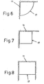
- the preconized shower plate can adopt any configuration corresponding to the different realization shapes of the showers in their installation, for example according to a rounded disposition (17) for the incorporation at the corners between walls (11), in the way represented on figure 6, or for a square disposition (18), also to be incorporated at the corners between walls (11), as the one represented on figure 7, or for a rectangular disposition (19) to be incorporated surrounded by walls (11), as the one represented on figure 8, being these shapes simply some practical examples, which do not have a limitative character.
Abstract
Description
Claims (3)
- Shower plate including a base which forms a gutter (1), expending as a frame around a central opening and forming the external contour of the shower, there being incorporated supported on the base a plate (6) which covers the surface of the assembly until near the external walls of the gutter, with respect to which a small opening (7) is left free around the contour for the evacuation of water, characterised in that the bottom of the gutter is inclined sideways towards the inside, there being provided at the lower part a side drainpipe (2) expending into the central opening and in that the plate is supporter on its seating with the inclusion of an elastic joint (8), providing uniform support and a watertight closure, there being no fixture between the gutter and the surface plate, so that the plate can be simply moved away by lifting it off.
- Installation of the shower plate of claim 1, characterized in that the base gutter (1) is situated inserted in the corresponding ground masonry (10), determining the outer walls of the mentioned gutter (1) some wings (4) which are include under the floor covering (10) in the contour of the installation, or in connection with the wall masonry (11) of the area which corresponds with the mentioned installation contour.
- Installation of the shower plate of claim 1, according to claim 2, characterized in that the wings (4) of the gutter (1) finish up with an edge (5) turned upwards, by means of which the fastening is assured during the assembly.
Applications Claiming Priority (3)
| Application Number | Priority Date | Filing Date | Title |
|---|---|---|---|
| ES200000008U ES1045026Y (en) | 2000-01-04 | 2000-01-04 | PERFECTED SHOWER TRAY. |
| ES200000008U | 2000-01-04 | ||
| PCT/ES2000/000081 WO2001049157A1 (en) | 2000-01-04 | 2000-03-07 | Improved shower plate |
Publications (2)
| Publication Number | Publication Date |
|---|---|
| EP1250876A1 EP1250876A1 (en) | 2002-10-23 |
| EP1250876B1 true EP1250876B1 (en) | 2005-07-27 |
Family
ID=8491850
Family Applications (1)
| Application Number | Title | Priority Date | Filing Date |
|---|---|---|---|
| EP00907678A Expired - Lifetime EP1250876B1 (en) | 2000-01-04 | 2000-03-07 | Improved shower plate |
Country Status (6)
| Country | Link |
|---|---|
| US (1) | US6240578B1 (en) |
| EP (1) | EP1250876B1 (en) |
| AT (1) | ATE300226T1 (en) |
| DE (1) | DE60021612D1 (en) |
| ES (1) | ES1045026Y (en) |
| WO (1) | WO2001049157A1 (en) |
Cited By (1)
| Publication number | Priority date | Publication date | Assignee | Title |
|---|---|---|---|---|
| US9267736B2 (en) | 2011-04-18 | 2016-02-23 | Bradley Fixtures Corporation | Hand dryer with point of ingress dependent air delay and filter sensor |
Families Citing this family (31)
| Publication number | Priority date | Publication date | Assignee | Title |
|---|---|---|---|---|
| GB2369568B (en) * | 2000-11-29 | 2004-03-10 | Beldore Ltd | Shower tray |
| US6571406B2 (en) * | 2000-12-02 | 2003-06-03 | Michael Gerloff | Supporting body for a shower tub |
| DE10059982C1 (en) | 2000-12-02 | 2002-06-20 | Michael Gerloff | Carrier body for a shower tray |
| DE10146874C1 (en) * | 2001-09-24 | 2002-10-02 | Juergen Klein | Horizontal sanitary table for use as washbasin may be fastened to wall and has flat table top with circular slit to act as drain |
| US6631525B2 (en) * | 2001-10-26 | 2003-10-14 | Kohler Co. | Washing platform |
| US7000266B2 (en) * | 2001-10-26 | 2006-02-21 | Kohler Co. | Lavatory with a removable washing platform |
| ITBO20030236A1 (en) * | 2003-04-18 | 2004-10-19 | Teuco Guzzini Spa | CABIN PROVIDED WITH A STEAM GENERATOR. |
| FR2861277B1 (en) | 2003-10-24 | 2006-01-06 | Lazer | SHOWER SOIL AND METHOD FOR PRODUCING THE SAME |
| EP1779754A1 (en) * | 2005-10-29 | 2007-05-02 | Dieter Preissing | Shower board with drain channel system |
| US8209795B2 (en) * | 2007-03-17 | 2012-07-03 | Cook Joseph R | Prefabricated shower pan having varying sidewall heights and method of attaching a modular curb |
| US8141183B2 (en) * | 2007-03-17 | 2012-03-27 | Cook Joseph R | Method for manufacturing a prefabricated modular shower curb and associated modular shower curb |
| US8141182B2 (en) | 2007-03-17 | 2012-03-27 | Cook Joseph R | Method of manufacturing and installation of prefabricated shower bench and associated shower bench |
| US20080222793A1 (en) * | 2007-03-17 | 2008-09-18 | Tile Redi, Llc | Ribbed prefabricated polyurethane shower module |
| US8789316B2 (en) | 2009-05-05 | 2014-07-29 | Joseph R. Cook | Waterproof juncture |
| US8112831B2 (en) | 2007-03-17 | 2012-02-14 | Cook Joseph R | Methods of manufacturing and installation of prefabricated shower benches and associated shower benches |
| US8307582B2 (en) | 2007-03-17 | 2012-11-13 | Tile Redi, Llc | Shower enclosure design and assembly methods using prefabricated shower benches |
| US8375480B2 (en) * | 2007-03-17 | 2013-02-19 | Tile Redi, Llc | Method for manufacturing a prefabricated shower module |
| US8181286B2 (en) * | 2007-03-17 | 2012-05-22 | Cook Joseph R | Drain wall for a prefabricated shower module |
| GB2462856B (en) * | 2008-08-22 | 2012-10-17 | Impey Showers Ltd | Shower assemblies |
| FR2936404B1 (en) * | 2008-09-29 | 2013-01-04 | Jedo | SINGLE-LEVEL SHOWER DEVICE WITH SURROUNDING SOIL |
| DE102009055934A1 (en) * | 2009-11-27 | 2011-06-01 | Stephan Wedi | Shower drain system and receiving element for a shower drain system |
| US8474068B2 (en) * | 2010-01-05 | 2013-07-02 | Noble Company | Trench shower drain |
| US8561224B2 (en) * | 2010-02-17 | 2013-10-22 | Joseph B. Cook | Handicapped accessible shower enclosure with ramp and/or floor pan |
| DE102010015856B4 (en) | 2010-03-08 | 2012-01-12 | Rolf Peissing | floor element |
| US9414720B2 (en) * | 2014-01-28 | 2016-08-16 | Alfredo Salvatori S.R.L. | Shower tray |
| ES2589633B2 (en) * | 2015-05-14 | 2017-06-09 | Cnes. M. Montero Pascual S.L. | Flat washbasin with tray |
| WO2016181007A1 (en) * | 2015-05-14 | 2016-11-17 | Cnes. M. Montero Pascual,S.L. | Flat surface for sinks and shower pans with drainage by means of channels |
| EP3251572B1 (en) * | 2016-06-02 | 2021-12-01 | Geberit International AG | A frame for a shower cubicle tray |
| GB2555645A (en) * | 2016-11-08 | 2018-05-09 | Carrington Lloyd | Shower floor |
| DE102021107883A1 (en) | 2021-03-29 | 2022-09-29 | Andrew Taupitz | Substructure element for a shower floor element and shower floor element, method for its installation |
| US11773603B2 (en) | 2021-09-23 | 2023-10-03 | Tile Redi, Llc | Reinforced floors for modular bathrooms |
Family Cites Families (7)
| Publication number | Priority date | Publication date | Assignee | Title |
|---|---|---|---|---|
| US1825355A (en) * | 1930-05-28 | 1931-09-29 | John J Keefe | Shower bath |
| DE6920922U (en) * | 1968-05-30 | 1969-10-23 | Bergmark Nils R | FLOOR FOR SHOWER CABIN |
| GB1590791A (en) | 1978-05-10 | 1981-06-10 | Foldor Ltd | Shower base |
| GB2108382B (en) | 1981-11-04 | 1985-09-04 | John Christopher King | Shower tray |
| FR2562409B1 (en) | 1984-04-04 | 1986-08-01 | Schoofs Jean Francois | SHOWER ENCLOSURE |
| GB2306316B (en) | 1995-10-18 | 1999-09-29 | Beldore Ltd | Shower trays |
| EP0774226B1 (en) | 1995-11-17 | 1998-05-27 | Enrique Graells Pane | Shower base |
-
2000
- 2000-01-04 ES ES200000008U patent/ES1045026Y/en not_active Expired - Fee Related
- 2000-02-08 US US09/500,233 patent/US6240578B1/en not_active Expired - Fee Related
- 2000-03-07 AT AT00907678T patent/ATE300226T1/en not_active IP Right Cessation
- 2000-03-07 EP EP00907678A patent/EP1250876B1/en not_active Expired - Lifetime
- 2000-03-07 WO PCT/ES2000/000081 patent/WO2001049157A1/en active IP Right Grant
- 2000-03-07 DE DE60021612T patent/DE60021612D1/en not_active Expired - Lifetime
Cited By (1)
| Publication number | Priority date | Publication date | Assignee | Title |
|---|---|---|---|---|
| US9267736B2 (en) | 2011-04-18 | 2016-02-23 | Bradley Fixtures Corporation | Hand dryer with point of ingress dependent air delay and filter sensor |
Also Published As
| Publication number | Publication date |
|---|---|
| EP1250876A1 (en) | 2002-10-23 |
| ES1045026U (en) | 2000-07-01 |
| US6240578B1 (en) | 2001-06-05 |
| WO2001049157A1 (en) | 2001-07-12 |
| DE60021612D1 (en) | 2005-09-01 |
| ES1045026Y (en) | 2001-06-01 |
| ATE300226T1 (en) | 2005-08-15 |
Similar Documents
| Publication | Publication Date | Title |
|---|---|---|
| EP1250876B1 (en) | Improved shower plate | |
| US6571406B2 (en) | Supporting body for a shower tub | |
| EP1287213B2 (en) | A drain and a building structure having a drain | |
| EP1571954B1 (en) | Prefabricated shower pan with integrally molded curb reinforcements | |
| CA2754328A1 (en) | Reversible low profile shower base | |
| MXPA06010567A (en) | A shower enclosure and base. | |
| HU226388B1 (en) | Shower tray | |
| JP2009526149A (en) | Siphon system obtained directly during the molding of sanitary ware | |
| GB2266735A (en) | Sanitary module | |
| IT201800007107A1 (en) | Self-cleaning sanitary and cleaning method | |
| EP2728078B1 (en) | Wall drain with height adjustable inflow opening | |
| DK1783285T3 (en) | Adjustable rørkrans for sanitary floor drain | |
| KR200295976Y1 (en) | Drain trap | |
| AU785196B2 (en) | Shower base | |
| KR101148237B1 (en) | An apparatus of a drain for bathroom | |
| EP1464768A3 (en) | Floor drain | |
| WO2003106775A2 (en) | Odour control apparatus for toilets | |
| KR102589224B1 (en) | Wall mounted type tile washstand | |
| KR102589225B1 (en) | Construction method of wall mounted type tile washstand | |
| CN212926317U (en) | Toilet chassis | |
| JP7317677B2 (en) | Washbasin and construction method of the washbasin | |
| EP2216449B1 (en) | Drain with inspection hole | |
| JP3340033B2 (en) | Bathroom waterproof pan | |
| GB2102039A (en) | Built-in closet and/bidet | |
| KR200182301Y1 (en) | The upper frame and plate of drain piping apparatus |
Legal Events
| Date | Code | Title | Description |
|---|---|---|---|
| PUAI | Public reference made under article 153(3) epc to a published international application that has entered the european phase |
Free format text: ORIGINAL CODE: 0009012 |
|
| 17P | Request for examination filed |
Effective date: 20020731 |
|
| AK | Designated contracting states |
Kind code of ref document: A1 Designated state(s): AT BE CH CY DE DK ES FI FR GB GR IE IT LI LU MC NL PT SE |
|
| GRAP | Despatch of communication of intention to grant a patent |
Free format text: ORIGINAL CODE: EPIDOSNIGR1 |
|
| GRAS | Grant fee paid |
Free format text: ORIGINAL CODE: EPIDOSNIGR3 |
|
| GRAA | (expected) grant |
Free format text: ORIGINAL CODE: 0009210 |
|
| AK | Designated contracting states |
Kind code of ref document: B1 Designated state(s): AT BE CH CY DE DK ES FI FR GB GR IE IT LI LU MC NL PT SE |
|
| PG25 | Lapsed in a contracting state [announced via postgrant information from national office to epo] |
Ref country code: LI Free format text: LAPSE BECAUSE OF FAILURE TO SUBMIT A TRANSLATION OF THE DESCRIPTION OR TO PAY THE FEE WITHIN THE PRESCRIBED TIME-LIMIT Effective date: 20050727 Ref country code: CH Free format text: LAPSE BECAUSE OF FAILURE TO SUBMIT A TRANSLATION OF THE DESCRIPTION OR TO PAY THE FEE WITHIN THE PRESCRIBED TIME-LIMIT Effective date: 20050727 Ref country code: BE Free format text: LAPSE BECAUSE OF FAILURE TO SUBMIT A TRANSLATION OF THE DESCRIPTION OR TO PAY THE FEE WITHIN THE PRESCRIBED TIME-LIMIT Effective date: 20050727 Ref country code: NL Free format text: LAPSE BECAUSE OF FAILURE TO SUBMIT A TRANSLATION OF THE DESCRIPTION OR TO PAY THE FEE WITHIN THE PRESCRIBED TIME-LIMIT Effective date: 20050727 Ref country code: AT Free format text: LAPSE BECAUSE OF FAILURE TO SUBMIT A TRANSLATION OF THE DESCRIPTION OR TO PAY THE FEE WITHIN THE PRESCRIBED TIME-LIMIT Effective date: 20050727 Ref country code: FI Free format text: LAPSE BECAUSE OF FAILURE TO SUBMIT A TRANSLATION OF THE DESCRIPTION OR TO PAY THE FEE WITHIN THE PRESCRIBED TIME-LIMIT Effective date: 20050727 Ref country code: IT Free format text: LAPSE BECAUSE OF FAILURE TO SUBMIT A TRANSLATION OF THE DESCRIPTION OR TO PAY THE FEE WITHIN THE PRESCRIBED TIME-LIMIT;WARNING: LAPSES OF ITALIAN PATENTS WITH EFFECTIVE DATE BEFORE 2007 MAY HAVE OCCURRED AT ANY TIME BEFORE 2007. THE CORRECT EFFECTIVE DATE MAY BE DIFFERENT FROM THE ONE RECORDED. Effective date: 20050727 |
|
| REG | Reference to a national code |
Ref country code: GB Ref legal event code: FG4D |
|
| REG | Reference to a national code |
Ref country code: CH Ref legal event code: EP |
|
| REG | Reference to a national code |
Ref country code: IE Ref legal event code: FG4D |
|
| REF | Corresponds to: |
Ref document number: 60021612 Country of ref document: DE Date of ref document: 20050901 Kind code of ref document: P |
|
| PG25 | Lapsed in a contracting state [announced via postgrant information from national office to epo] |
Ref country code: GR Free format text: LAPSE BECAUSE OF FAILURE TO SUBMIT A TRANSLATION OF THE DESCRIPTION OR TO PAY THE FEE WITHIN THE PRESCRIBED TIME-LIMIT Effective date: 20051027 Ref country code: SE Free format text: LAPSE BECAUSE OF FAILURE TO SUBMIT A TRANSLATION OF THE DESCRIPTION OR TO PAY THE FEE WITHIN THE PRESCRIBED TIME-LIMIT Effective date: 20051027 Ref country code: DK Free format text: LAPSE BECAUSE OF FAILURE TO SUBMIT A TRANSLATION OF THE DESCRIPTION OR TO PAY THE FEE WITHIN THE PRESCRIBED TIME-LIMIT Effective date: 20051027 |
|
| PG25 | Lapsed in a contracting state [announced via postgrant information from national office to epo] |
Ref country code: DE Free format text: LAPSE BECAUSE OF FAILURE TO SUBMIT A TRANSLATION OF THE DESCRIPTION OR TO PAY THE FEE WITHIN THE PRESCRIBED TIME-LIMIT Effective date: 20051028 |
|
| PG25 | Lapsed in a contracting state [announced via postgrant information from national office to epo] |
Ref country code: ES Free format text: LAPSE BECAUSE OF FAILURE TO SUBMIT A TRANSLATION OF THE DESCRIPTION OR TO PAY THE FEE WITHIN THE PRESCRIBED TIME-LIMIT Effective date: 20051107 |
|
| PG25 | Lapsed in a contracting state [announced via postgrant information from national office to epo] |
Ref country code: PT Free format text: LAPSE BECAUSE OF FAILURE TO SUBMIT A TRANSLATION OF THE DESCRIPTION OR TO PAY THE FEE WITHIN THE PRESCRIBED TIME-LIMIT Effective date: 20051227 |
|
| REG | Reference to a national code |
Ref country code: CH Ref legal event code: PL |
|
| NLV1 | Nl: lapsed or annulled due to failure to fulfill the requirements of art. 29p and 29m of the patents act | ||
| PG25 | Lapsed in a contracting state [announced via postgrant information from national office to epo] |
Ref country code: IE Free format text: LAPSE BECAUSE OF NON-PAYMENT OF DUE FEES Effective date: 20060307 Ref country code: GB Free format text: LAPSE BECAUSE OF NON-PAYMENT OF DUE FEES Effective date: 20060307 |
|
| PG25 | Lapsed in a contracting state [announced via postgrant information from national office to epo] |
Ref country code: MC Free format text: LAPSE BECAUSE OF NON-PAYMENT OF DUE FEES Effective date: 20060331 Ref country code: LU Free format text: LAPSE BECAUSE OF NON-PAYMENT OF DUE FEES Effective date: 20060331 |
|
| PLBE | No opposition filed within time limit |
Free format text: ORIGINAL CODE: 0009261 |
|
| STAA | Information on the status of an ep patent application or granted ep patent |
Free format text: STATUS: NO OPPOSITION FILED WITHIN TIME LIMIT |
|
| 26N | No opposition filed |
Effective date: 20060428 |
|
| EN | Fr: translation not filed | ||
| PG25 | Lapsed in a contracting state [announced via postgrant information from national office to epo] |
Ref country code: FR Free format text: LAPSE BECAUSE OF FAILURE TO SUBMIT A TRANSLATION OF THE DESCRIPTION OR TO PAY THE FEE WITHIN THE PRESCRIBED TIME-LIMIT Effective date: 20060922 |
|
| GBPC | Gb: european patent ceased through non-payment of renewal fee |
Effective date: 20060307 |
|
| REG | Reference to a national code |
Ref country code: IE Ref legal event code: MM4A |
|
| PG25 | Lapsed in a contracting state [announced via postgrant information from national office to epo] |
Ref country code: CY Free format text: LAPSE BECAUSE OF FAILURE TO SUBMIT A TRANSLATION OF THE DESCRIPTION OR TO PAY THE FEE WITHIN THE PRESCRIBED TIME-LIMIT Effective date: 20050727 Ref country code: FR Free format text: LAPSE BECAUSE OF FAILURE TO SUBMIT A TRANSLATION OF THE DESCRIPTION OR TO PAY THE FEE WITHIN THE PRESCRIBED TIME-LIMIT Effective date: 20050727 |