EP1260258A2 - System and method for transporting and deoxygenating a solution - Google Patents
System and method for transporting and deoxygenating a solution Download PDFInfo
- Publication number
- EP1260258A2 EP1260258A2 EP20020011293 EP02011293A EP1260258A2 EP 1260258 A2 EP1260258 A2 EP 1260258A2 EP 20020011293 EP20020011293 EP 20020011293 EP 02011293 A EP02011293 A EP 02011293A EP 1260258 A2 EP1260258 A2 EP 1260258A2
- Authority
- EP
- European Patent Office
- Prior art keywords
- solution
- deoxygenating
- deoxygenated
- dispensing
- oxygen
- Prior art date
- Legal status (The legal status is an assumption and is not a legal conclusion. Google has not performed a legal analysis and makes no representation as to the accuracy of the status listed.)
- Ceased
Links
Images

Classifications
-
- B—PERFORMING OPERATIONS; TRANSPORTING
- B01—PHYSICAL OR CHEMICAL PROCESSES OR APPARATUS IN GENERAL
- B01D—SEPARATION
- B01D19/00—Degasification of liquids
- B01D19/0068—General arrangements, e.g. flowsheets
-
- Y—GENERAL TAGGING OF NEW TECHNOLOGICAL DEVELOPMENTS; GENERAL TAGGING OF CROSS-SECTIONAL TECHNOLOGIES SPANNING OVER SEVERAL SECTIONS OF THE IPC; TECHNICAL SUBJECTS COVERED BY FORMER USPC CROSS-REFERENCE ART COLLECTIONS [XRACs] AND DIGESTS
- Y10—TECHNICAL SUBJECTS COVERED BY FORMER USPC
- Y10T—TECHNICAL SUBJECTS COVERED BY FORMER US CLASSIFICATION
- Y10T137/00—Fluid handling
- Y10T137/0318—Processes
- Y10T137/0402—Cleaning, repairing, or assembling
- Y10T137/0419—Fluid cleaning or flushing
- Y10T137/0424—Liquid cleaning or flushing
Definitions
- the present invention provides a system and a method for transporting and deoxygenating a solution. This system is useful for a manufacture involving transportation and deoxygenation of a solution.
- extended-wear contact lenses would display high oxygen permeability, high ion permeability, good wettability, adequate on-eye movement, and tear exchange ability, all of which are required to maintain corneal health and wear comfort.
- US-A-5,849,811 teaches a process and polymer composition for making extended-wear lenses.
- the extended-wear lenses made according to the methods disclosed in US-A-5,849,811 can have a balance of oxygen permeability and ion or water permeability, with the ion or water permeability being sufficient to provide good on-eye movement, such that a good tear exchange occurs between the lens and the eye.
- US-A-5,849,811 discloses that the ion and/or water permeability of lens materials may be increased by initiating and completing polymerization in an atmosphere which is substantially free of oxygen. Deoxygenating a polymer composition (formulation) and transporting the deoxygenated polymer composition (formulation) may be required in manufacture of such extended-wear lenses before making extended-wear lenses by molding.
- the object of the invention is to develop a system capable of deoxygenating a solution, e.g. a polymer solution, transporting the deoxygenated solution, monitoring continuously the oxygen content in the solution, maintaining the oxygen content in the solution at a low level, and dispensing solution into molds.
- a solution e.g. a polymer solution
- An embodiment of the invention is an automated system for transporting and deoxygenating a solution.
- the system is designed to:
- An embodiment of the system of the invention comprises: a deoxygenating means, a pumping means, an oxygen analyzer, a solution collection system, a solution dispensing system, and a computer system, wherein the computer system:
- a further embodiment of the invention is a method for deoxygenating and transporting a solution.
- the method comprises:
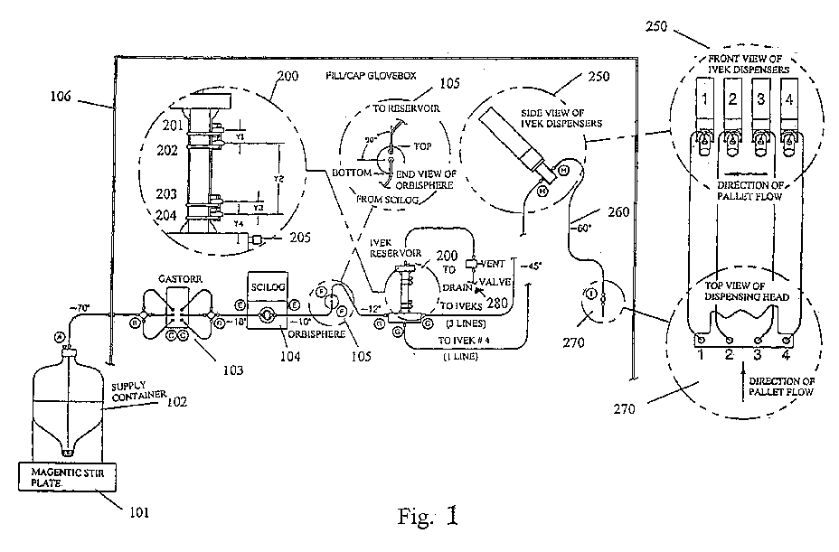
- FIG. 1 The only drawing figure (Fig. 1) is a schematic representation of a preferred embodiment of an automated system for de-oxygenating and dispensing a solution according to the invention.
- the system for de-oxygenating and dispensing a solution comprises a pumping means 104 (for example a Scilog pump) that can draw a solution from a container 102 .
- the solution is mixed using a stirring means 101 (such as a magnetic stir plate) and pumped through a de-oxygenating mean 103 (e.g., a Gastorr deoxygenating device) and an oxygen analyzer 105 (e.g., an Orbisphere oxygen analyzer).
- the concentration of oxygen in the solution is constantly monitored by the oxygen analyzer 105 and the information about the oxygen concentration is fed to a computer system (e.g., a HMI computer, not shown) which controls the operation of the whole system.
- a computer system e.g., a HMI computer, not shown
- the computer system can adjust the speed of solution pumping so as to adjust the solution residence time in the deoxygenating means, according to the received information about the oxygen concentration. Longer residence time would remove more oxygen from the solution. Conversely, less oxygen would be removed from the solution for a shorter residence time.
- the solution is fed into a solution collection system 200 (reservoir) which comprises multiple liquid level switches 201 , 202 , 203 , and 204 .
- a dispensing system 250 (for example, IVEK dispensing pumps) pumps from the solution collection system 200 and dispenses a given amount of solution through tubing 260 to receivers e.g., lens molds (not shown) in a Fill/Cap station 270.
- the de-oxygenating mean 103, the pumping means 104 , the oxygen analyzer 105 , the solution collection system 200 and the dispensing system 250 are located inside a Fill/Cap glove box 106 which is airtight and filled with an inert gas, for example, nitrogen or argon.
- the solution is dispensed into each of a plurality of receivers in a prescribed amount.
- the receivers are preferably located in a Fill/Cap station 270 which is filled with an inert gas to have a positive pressure.
- the system can also further comprise a waste container 280 located inside the Fill/Cap glove box.
- the solution collection system 200 can be a IVEK reservoir assembly and comprises four switches. These four switches are arranged as follow: the distance Y1 between switches 201 and 202 is no more than 5/8"; the distance Y2 between switches 202 and 203 about 3 and 3/8"; the distance Y3 between switches 203 and 204 about 5/8"; and the distance Y4 between switch 204 and draining level 205 about 7/8".
- the system with a configuration as shown in Fig. 1 operates under computer control in the following modes:
- the HMI continuously monitors the output of the Orbisphere oxygen analyzer 105 during this operation to ensure that the formulation is properly deoxygenated.
- the system may begin automatic dispensing operations once the AKNOWLEDGE, AUTO CYCLE, and CYCLE START buttons have been selected at the HMI.
- the HMI monitors all reservoir switches during automatic operation for fault conditions. Switches #1 and #4 serve dual purposes as high/low liquid level alarms during automatic operation, and as level controls during SHUTDOWN and STARTUP commands respectively. In addition, the HMI once again monitors the status of the Orbisphere oxygen analyzer 105 to ensure that the solution is properly deoxygenated. Finally, the HMI continuously monitors idle status of the dispensing system and automatically dispenses shots on an interval timer to prevent unwanted material polymerization which would otherwise occur.
Abstract
Description
- The present invention provides a system and a method for transporting and deoxygenating a solution. This system is useful for a manufacture involving transportation and deoxygenation of a solution.
- In recent years, a wide variety of research has been carried out to develop polymeric materials useful for making extended-wear contact lenses which affect minimally corneal health and give wearers maximal comfort. Ideally, extended-wear contact lenses would display high oxygen permeability, high ion permeability, good wettability, adequate on-eye movement, and tear exchange ability, all of which are required to maintain corneal health and wear comfort.
- There have been many attempts to blend different polymers having different properties to make extended-wear lenses having some of the above-mentioned desired properties. For example, US-A-5,849,811 teaches a process and polymer composition for making extended-wear lenses. The extended-wear lenses made according to the methods disclosed in US-A-5,849,811 can have a balance of oxygen permeability and ion or water permeability, with the ion or water permeability being sufficient to provide good on-eye movement, such that a good tear exchange occurs between the lens and the eye. US-A-5,849,811 discloses that the ion and/or water permeability of lens materials may be increased by initiating and completing polymerization in an atmosphere which is substantially free of oxygen. Deoxygenating a polymer composition (formulation) and transporting the deoxygenated polymer composition (formulation) may be required in manufacture of such extended-wear lenses before making extended-wear lenses by molding.
- Therefore, there is a need for a system and method for deoxygenating formulations and transporting deoxygenated formulations in an industrial setting for manufacturing contact lenses. Such system and method preferably can be adapted to automated practices and perform with consistency.
- The object of the invention is to develop a system capable of deoxygenating a solution, e.g. a polymer solution, transporting the deoxygenated solution, monitoring continuously the oxygen content in the solution, maintaining the oxygen content in the solution at a low level, and dispensing solution into molds.
- An embodiment of the invention is an automated system for transporting and deoxygenating a solution. The system is designed to:
- 1) transport a solution through a de-oxygenating device;
- 2) continuously monitor the oxygen concentration of the deoxygenated solution;
- 3) fill the solution in a reservoir and automatically maintain solution level;
- 4) automatically dispense the solution as requested; and
- 5) perform automatically solution preparation, and start-up and shutdown operations.
-
- An embodiment of the system of the invention comprises: a deoxygenating means, a pumping means, an oxygen analyzer, a solution collection system, a solution dispensing system, and a computer system, wherein the computer system:
- a) controls the pumping means to pump the solution from the container through the deoxygenating means in which oxygen is purged from the solution and through the oxygen analyzer which monitors oxygen concentration in the system and provides a feedback to the computer system to adjust operations of the system to ensure that the solution is properly deoxygenated;
- b) controls the deoxygenating means to deoxygenate the solution;
- c) controls the pump means to fill the solution collection system with the solution; and
- d) controls the solution dispensing system to drain the solution from the solution collection system and to dispense into each of one or more receivers a prescribed amount of the deoxygenated solution from the solution collection system.
-
- A further embodiment of the invention is a method for deoxygenating and transporting a solution. The method comprises:
- (a) displacing oxygen trapped in the above described system of the invention with a deoxygenated first solvent which is miscible with a second solvent used for preparing the solution and draining the deoxygenated first solvent from the solution collection system;
- (b) replacing the deoxygenated first solvent in the system with the solution that is deoxygenated; and
- (c) dispensing into each of one or more receivers a prescribed amount of the deoxygenated solution.
-
- The only drawing figure (Fig. 1) is a schematic representation of a preferred embodiment of an automated system for de-oxygenating and dispensing a solution according to the invention.
- Referring to Fig. 1, the system for de-oxygenating and dispensing a solution comprises a pumping means 104 (for example a Scilog pump) that can draw a solution from a
container 102. The solution is mixed using a stirring means 101 (such as a magnetic stir plate) and pumped through a de-oxygenating mean 103 (e.g., a Gastorr deoxygenating device) and an oxygen analyzer 105 (e.g., an Orbisphere oxygen analyzer). The concentration of oxygen in the solution is constantly monitored by theoxygen analyzer 105 and the information about the oxygen concentration is fed to a computer system (e.g., a HMI computer, not shown) which controls the operation of the whole system. The computer system can adjust the speed of solution pumping so as to adjust the solution residence time in the deoxygenating means, according to the received information about the oxygen concentration. Longer residence time would remove more oxygen from the solution. Conversely, less oxygen would be removed from the solution for a shorter residence time. After being tested in theoxygen analyzer 105, the solution is fed into a solution collection system 200 (reservoir) which comprises multipleliquid level switches solution collection system 200 and dispenses a given amount of solution throughtubing 260 to receivers e.g., lens molds (not shown) in a Fill/Cap station 270. Preferably, the de-oxygenating mean 103, the pumping means 104, theoxygen analyzer 105, thesolution collection system 200 and thedispensing system 250 are located inside a Fill/Cap glove box 106 which is airtight and filled with an inert gas, for example, nitrogen or argon. The solution is dispensed into each of a plurality of receivers in a prescribed amount. The receivers are preferably located in a Fill/Cap station 270 which is filled with an inert gas to have a positive pressure. The system can also further comprise awaste container 280 located inside the Fill/Cap glove box. - Preferably, the
solution collection system 200 can be a IVEK reservoir assembly and comprises four switches. These four switches are arranged as follow: the distance Y1 betweenswitches switches switches switch 204 and draininglevel 205 about 7/8". - The system with a configuration as shown in Fig. 1 operates under computer control in the following modes:
- PREPARE: In this mode, the
solution supply container 102 is replaced by one filled with ethanol. When the PREPARE button is selected at the HMI computer terminal, theScilog pump 104 draws ethanol from the container, through the Gastorrdeoxygenating device 103 and the Orbisphereoxygen analyzer 105, and into thereservoir 200 at 100% pump speed. Thepump 104 continues to fill thereservoir 200 until the ethanol passes out the overfill line and begins to collect in thewaste container 280 inside the Fill/Cap glovebox 106. In this manner, any oxygen present in the system (up through the reservoir) is displaced by ethanol. Once the cycle has finished (as determined by a preprogrammed timer), the operator selects the ACKNOWLEDGE button at the HMI to complete the operation. - STARTUP: Following oxygen displacement, the system must be drained of all ethanol and
replenished with deoxygenated formulation in preparation for dispensing into molds. In this
mode, the ethanol container is replaced with the solution supply container, and the cycle is
initiated by selecting the STARTUP button at the HMI. Once initiated, the IVEK
dispensing pumps 250 automatically turn on and drain the reservoir 200 a prescribed amount pastswitch # 4. During draining, thereservoir 200 is automatically back-filled with nitrogen supplied from the slightly positive pressure Fill/Cap glovebox 106. Once empty, the system automatically performs a multi-step process to transition from ethanol to pure formulation by refilling and draining thereservoir 200 as follows: - 1. Fill to
level switch # 2 with formulation at 75% Scilog pump motor speed. - 2. Drain reservoir and lines via IVEKs as described previously.
- 3. Fill to
level switch # 2 with formulation at 18% Scilog pump motor speed. - 4. Drain reservoir and lines via IVEKs as described previously.
- 5. Repeat
steps - 6. Charge IVEK dispensers with formulation and refill reservoir to
level switch # 3 at 18% Scilog pump motor speed. -
- The HMI continuously monitors the output of the
Orbisphere oxygen analyzer 105 during this operation to ensure that the formulation is properly deoxygenated. The system may begin automatic dispensing operations once the AKNOWLEDGE, AUTO CYCLE, and CYCLE START buttons have been selected at the HMI. - DISPENSE: As pallets fitted with clamp fixtures containing contact lens molds arrive at the
Fill/
Cap station 270, all four IVEKs are automatically signaled to simultaneously dispense the prescribed amount of formulation into the first four awaiting lens molds. The dispensing head indexes across the pallet, filling the remaining molds until complete. Pallets leave the Fill/Cap station 270 once the filling and mold capping operations are complete. Dispensing continues on successive lens molds until the IVEK pump chambers are near empty. Following the last full shot dispense of the solution, all IVEKs simultaneously recharge their chambers by drawing the solution from thereservoir 200. TheScilog pump 104 automatically refills thereservoir 200 to switch #3 so as to maintain an adequate amount of deoxygenated solution for the next chamber refill. The deoxygenating/re-filling operation is complete well in advance of the next chamber refill operation. -
- The HMI monitors all reservoir switches during automatic operation for fault conditions.
Switches # 1 and #4 serve dual purposes as high/low liquid level alarms during automatic operation, and as level controls during SHUTDOWN and STARTUP commands respectively. In addition, the HMI once again monitors the status of theOrbisphere oxygen analyzer 105 to ensure that the solution is properly deoxygenated. Finally, the HMI continuously monitors idle status of the dispensing system and automatically dispenses shots on an interval timer to prevent unwanted material polymerization which would otherwise occur. - SHUTDOWN: Following completion of automatic operation the
solution supply container 102 is replaced with the ethanol container, and the cycle is initiated by selecting the SHUTDOWN button at the HMI. In a manner similar to the STARTUP operation, the system automatically performs a multi-step process to transition from formulation back to pure ethanol by draining and refilling the reservoir as follows: - 1. Drain reservoir and lines via IVEKs as described previously.
- 2. Fill to
level switch # 1 with ethanol at 100% Scilog pump motor speed. - 3. Repeat steps 1 and 2 three times.
- 4. Drain reservoir to switch #3.
-
- System operation is complete once the ACKNOWLEDGE button has been selected on the HMI.
Claims (9)
Applications Claiming Priority (4)
| Application Number | Priority Date | Filing Date | Title |
|---|---|---|---|
| US29298001P | 2001-05-23 | 2001-05-23 | |
| US292980P | 2001-05-23 | ||
| US33470901P | 2001-10-31 | 2001-10-31 | |
| US334709P | 2001-10-31 |
Publications (2)
| Publication Number | Publication Date |
|---|---|
| EP1260258A2 true EP1260258A2 (en) | 2002-11-27 |
| EP1260258A3 EP1260258A3 (en) | 2002-12-18 |
Family
ID=26967671
Family Applications (1)
| Application Number | Title | Priority Date | Filing Date |
|---|---|---|---|
| EP20020011293 Ceased EP1260258A3 (en) | 2001-05-23 | 2002-05-22 | System and method for transporting and deoxygenating a solution |
Country Status (3)
| Country | Link |
|---|---|
| US (1) | US6740139B2 (en) |
| EP (1) | EP1260258A3 (en) |
| JP (1) | JP4260417B2 (en) |
Cited By (1)
| Publication number | Priority date | Publication date | Assignee | Title |
|---|---|---|---|---|
| CN104857743A (en) * | 2014-02-21 | 2015-08-26 | 中国石油化工股份有限公司 | Polymer solution sealed deoxygenation device and method |
Families Citing this family (8)
| Publication number | Priority date | Publication date | Assignee | Title |
|---|---|---|---|---|
| JP2004249215A (en) * | 2003-02-20 | 2004-09-09 | Fuji Photo Film Co Ltd | Deaeration system of liquid and deaeration method of liquid |
| US7625197B2 (en) * | 2005-09-12 | 2009-12-01 | Johnson & Johnson Vision Care, Inc. | Devices and processes for performing degassing operations |
| US7989593B1 (en) | 2010-05-27 | 2011-08-02 | Bing Lou Wong | Method for the preparation of a high-temperature stable oxygen-carrier-containing pharmaceutical composition and the use thereof |
| US7932356B1 (en) | 2010-06-23 | 2011-04-26 | Bing Lou Wong | Method for the preparation of a heat stable oxygen carrier-containing pharmaceutical composition |
| US8048856B1 (en) | 2010-06-23 | 2011-11-01 | Billion King, Ltd. | Treatment methods using a heat stable oxygen carrier-containing pharmaceutical composition |
| US8084581B1 (en) | 2011-04-29 | 2011-12-27 | Bing Lou Wong | Method for removing unmodified hemoglobin from cross-linked hemoglobin solutions including polymeric hemoglobin with a high temperature short time heat treatment apparatus |
| US20130052232A1 (en) | 2011-08-31 | 2013-02-28 | Bing Lou Wong | Method for the preparation of a heat stable oxygen carrier-containing composition facilating beta-beta cross-linking |
| JP6077404B2 (en) * | 2013-07-01 | 2017-02-08 | 本田技研工業株式会社 | Resin molding apparatus and resin molding method |
Citations (3)
| Publication number | Priority date | Publication date | Assignee | Title |
|---|---|---|---|---|
| JPS6065704A (en) * | 1983-09-17 | 1985-04-15 | Japan Storage Battery Co Ltd | Control of oxygen concentration |
| US5281579A (en) * | 1984-03-23 | 1994-01-25 | Baxter International Inc. | Purified virus-free hemoglobin solutions and method for making same |
| US5922249A (en) * | 1995-12-08 | 1999-07-13 | Novartis Ag | Ophthalmic lens production process |
Family Cites Families (3)
| Publication number | Priority date | Publication date | Assignee | Title |
|---|---|---|---|---|
| US3751879A (en) | 1971-04-26 | 1973-08-14 | Instrumentation Specialties Co | Apparatus for reducing the dissolved gas concentration in a liquid |
| US4315760A (en) | 1980-01-17 | 1982-02-16 | Bij De Leij Jan D | Method and apparatus for degasing, during transportation, a confined volume of liquid to be measured |
| US5814134A (en) | 1994-06-10 | 1998-09-29 | Johnson & Johnson Vision Products, Inc. | Apparatus and method for degassing deionized water for inspection and packaging |
-
2002
- 2002-05-20 JP JP2002143972A patent/JP4260417B2/en not_active Expired - Fee Related
- 2002-05-22 US US10/153,047 patent/US6740139B2/en not_active Expired - Lifetime
- 2002-05-22 EP EP20020011293 patent/EP1260258A3/en not_active Ceased
Patent Citations (3)
| Publication number | Priority date | Publication date | Assignee | Title |
|---|---|---|---|---|
| JPS6065704A (en) * | 1983-09-17 | 1985-04-15 | Japan Storage Battery Co Ltd | Control of oxygen concentration |
| US5281579A (en) * | 1984-03-23 | 1994-01-25 | Baxter International Inc. | Purified virus-free hemoglobin solutions and method for making same |
| US5922249A (en) * | 1995-12-08 | 1999-07-13 | Novartis Ag | Ophthalmic lens production process |
Non-Patent Citations (1)
| Title |
|---|
| PATENT ABSTRACTS OF JAPAN vol. 009, no. 196 (C-297), 13 August 1985 (1985-08-13) & JP 60 065704 A (NIHON DENCHI KK), 15 April 1985 (1985-04-15) * |
Cited By (2)
| Publication number | Priority date | Publication date | Assignee | Title |
|---|---|---|---|---|
| CN104857743A (en) * | 2014-02-21 | 2015-08-26 | 中国石油化工股份有限公司 | Polymer solution sealed deoxygenation device and method |
| CN104857743B (en) * | 2014-02-21 | 2017-01-18 | 中国石油化工股份有限公司 | Polymer solution sealed deoxygenation device and method |
Also Published As
| Publication number | Publication date |
|---|---|
| JP2003019714A (en) | 2003-01-21 |
| US6740139B2 (en) | 2004-05-25 |
| EP1260258A3 (en) | 2002-12-18 |
| JP4260417B2 (en) | 2009-04-30 |
| US20030029317A1 (en) | 2003-02-13 |
Similar Documents
| Publication | Publication Date | Title |
|---|---|---|
| US20100102463A1 (en) | Method For Mixing A Fluid With At Least One Further Substance And Degassing The Mixture And For Delivering The Mixture | |
| EP1260258A2 (en) | System and method for transporting and deoxygenating a solution | |
| JP4004573B2 (en) | Contact lens mold filling and assembly equipment | |
| EP1368273B1 (en) | Dispensing apparatus | |
| JP5419616B2 (en) | Bubble mixing prevention mechanism, liquid material discharging apparatus including the mechanism, and liquid material discharging method | |
| EP1780012B1 (en) | Colorant presentation for pad printing | |
| CA2524169A1 (en) | Methods of dispensing | |
| WO2007129010A1 (en) | Water carbonation apparatus | |
| CN101321543A (en) | Method and apparatus for injecting a metered quantity of a liquid into a chamber | |
| CN103423137B (en) | Move back and forth control apparatus and the controlling method of type pump | |
| CN101734490A (en) | Burden distribution method of cut tobacco storing cabinet | |
| EP2351638B1 (en) | Plastic lens manufacturing method and manufacturing device | |
| EP3799951B1 (en) | A dosing machine for dispensing metered quantities of fluid products, in particular for preparing paints, varnishes, dyes and the like | |
| CN2445447Y (en) | Device for adjusting electrolyte filling quantity for lead accumulator | |
| JP2003528299A (en) | Liquid distribution device | |
| JPH09274907A (en) | Method and apparatus for supplying electrolyte to battery | |
| CN113859603A (en) | Device and method for filling a syringe | |
| CN2400429Y (en) | Liquid-filling machine | |
| EP2970520B1 (en) | Method and apparatus for delaying polymerisation | |
| EP1808677B1 (en) | Automatic liquid density-regulating device | |
| CN219677288U (en) | Fuel cell reaction gas filling system | |
| CN113562679B (en) | Integrated production process of bottled purified water | |
| CN211595006U (en) | A irritate liquid machine for silane vitrification liquid | |
| JP2007185372A (en) | Liquid preparing device | |
| CN117342240A (en) | Small-package traditional Chinese medicine dispensing method |
Legal Events
| Date | Code | Title | Description |
|---|---|---|---|
| PUAI | Public reference made under article 153(3) epc to a published international application that has entered the european phase |
Free format text: ORIGINAL CODE: 0009012 |
|
| PUAL | Search report despatched |
Free format text: ORIGINAL CODE: 0009013 |
|
| AK | Designated contracting states |
Kind code of ref document: A2 Designated state(s): AT BE CH CY DE DK ES FI FR GB GR IE IT LI LU MC NL PT SE TR |
|
| AX | Request for extension of the european patent |
Free format text: AL;LT;LV;MK;RO;SI |
|
| AK | Designated contracting states |
Kind code of ref document: A3 Designated state(s): AT BE CH CY DE DK ES FI FR GB GR IE IT LI LU MC NL PT SE TR |
|
| AX | Request for extension of the european patent |
Free format text: AL;LT;LV;MK;RO;SI |
|
| 17P | Request for examination filed |
Effective date: 20020522 |
|
| RAP1 | Party data changed (applicant data changed or rights of an application transferred) |
Owner name: NOVARTIS PHARMA GMBH Owner name: NOVARTIS AG |
|
| RAP1 | Party data changed (applicant data changed or rights of an application transferred) |
Owner name: NOVARTIS AG Owner name: NOVARTIS PHARMA GMBH |
|
| R17P | Request for examination filed (corrected) |
Effective date: 20030522 |
|
| AKX | Designation fees paid |
Designated state(s): AT BE CH CY DE DK ES FI FR GB GR IE IT LI LU MC NL PT SE TR |
|
| 17Q | First examination report despatched |
Effective date: 20070522 |
|
| RAP1 | Party data changed (applicant data changed or rights of an application transferred) |
Owner name: NOVARTIS AG |
|
| STAA | Information on the status of an ep patent application or granted ep patent |
Free format text: STATUS: THE APPLICATION HAS BEEN REFUSED |
|
| 18R | Application refused |
Effective date: 20091020 |