EP1261213A1 - Projection-type display apparatus - Google Patents
Projection-type display apparatus Download PDFInfo
- Publication number
- EP1261213A1 EP1261213A1 EP02077916A EP02077916A EP1261213A1 EP 1261213 A1 EP1261213 A1 EP 1261213A1 EP 02077916 A EP02077916 A EP 02077916A EP 02077916 A EP02077916 A EP 02077916A EP 1261213 A1 EP1261213 A1 EP 1261213A1
- Authority
- EP
- European Patent Office
- Prior art keywords
- lens
- light
- color
- beams
- projection
- Prior art date
- Legal status (The legal status is an assumption and is not a legal conclusion. Google has not performed a legal analysis and makes no representation as to the accuracy of the status listed.)
- Withdrawn
Links
Images


Classifications
-
- G—PHYSICS
- G02—OPTICS
- G02B—OPTICAL ELEMENTS, SYSTEMS OR APPARATUS
- G02B3/00—Simple or compound lenses
- G02B3/0006—Arrays
- G02B3/0037—Arrays characterized by the distribution or form of lenses
- G02B3/0043—Inhomogeneous or irregular arrays, e.g. varying shape, size, height
-
- G—PHYSICS
- G02—OPTICS
- G02B—OPTICAL ELEMENTS, SYSTEMS OR APPARATUS
- G02B3/00—Simple or compound lenses
- G02B3/0006—Arrays
- G02B3/0037—Arrays characterized by the distribution or form of lenses
- G02B3/005—Arrays characterized by the distribution or form of lenses arranged along a single direction only, e.g. lenticular sheets
-
- G—PHYSICS
- G02—OPTICS
- G02B—OPTICAL ELEMENTS, SYSTEMS OR APPARATUS
- G02B3/00—Simple or compound lenses
- G02B3/0006—Arrays
- G02B3/0037—Arrays characterized by the distribution or form of lenses
- G02B3/0056—Arrays characterized by the distribution or form of lenses arranged along two different directions in a plane, e.g. honeycomb arrangement of lenses
-
- G—PHYSICS
- G02—OPTICS
- G02B—OPTICAL ELEMENTS, SYSTEMS OR APPARATUS
- G02B3/00—Simple or compound lenses
- G02B3/0006—Arrays
- G02B3/0037—Arrays characterized by the distribution or form of lenses
- G02B3/0062—Stacked lens arrays, i.e. refractive surfaces arranged in at least two planes, without structurally separate optical elements in-between
-
- G—PHYSICS
- G03—PHOTOGRAPHY; CINEMATOGRAPHY; ANALOGOUS TECHNIQUES USING WAVES OTHER THAN OPTICAL WAVES; ELECTROGRAPHY; HOLOGRAPHY
- G03B—APPARATUS OR ARRANGEMENTS FOR TAKING PHOTOGRAPHS OR FOR PROJECTING OR VIEWING THEM; APPARATUS OR ARRANGEMENTS EMPLOYING ANALOGOUS TECHNIQUES USING WAVES OTHER THAN OPTICAL WAVES; ACCESSORIES THEREFOR
- G03B21/00—Projectors or projection-type viewers; Accessories therefor
- G03B21/14—Details
- G03B21/20—Lamp housings
- G03B21/208—Homogenising, shaping of the illumination light
-
- G—PHYSICS
- G03—PHOTOGRAPHY; CINEMATOGRAPHY; ANALOGOUS TECHNIQUES USING WAVES OTHER THAN OPTICAL WAVES; ELECTROGRAPHY; HOLOGRAPHY
- G03B—APPARATUS OR ARRANGEMENTS FOR TAKING PHOTOGRAPHS OR FOR PROJECTING OR VIEWING THEM; APPARATUS OR ARRANGEMENTS EMPLOYING ANALOGOUS TECHNIQUES USING WAVES OTHER THAN OPTICAL WAVES; ACCESSORIES THEREFOR
- G03B33/00—Colour photography, other than mere exposure or projection of a colour film
- G03B33/10—Simultaneous recording or projection
- G03B33/12—Simultaneous recording or projection using beam-splitting or beam-combining systems, e.g. dichroic mirrors
-
- H—ELECTRICITY
- H04—ELECTRIC COMMUNICATION TECHNIQUE
- H04N—PICTORIAL COMMUNICATION, e.g. TELEVISION
- H04N9/00—Details of colour television systems
- H04N9/12—Picture reproducers
- H04N9/31—Projection devices for colour picture display, e.g. using electronic spatial light modulators [ESLM]
- H04N9/3102—Projection devices for colour picture display, e.g. using electronic spatial light modulators [ESLM] using two-dimensional electronic spatial light modulators
- H04N9/3105—Projection devices for colour picture display, e.g. using electronic spatial light modulators [ESLM] using two-dimensional electronic spatial light modulators for displaying all colours simultaneously, e.g. by using two or more electronic spatial light modulators
-
- H—ELECTRICITY
- H04—ELECTRIC COMMUNICATION TECHNIQUE
- H04N—PICTORIAL COMMUNICATION, e.g. TELEVISION
- H04N9/00—Details of colour television systems
- H04N9/12—Picture reproducers
- H04N9/31—Projection devices for colour picture display, e.g. using electronic spatial light modulators [ESLM]
- H04N9/3141—Constructional details thereof
- H04N9/315—Modulator illumination systems
- H04N9/3167—Modulator illumination systems for polarizing the light beam
-
- H—ELECTRICITY
- H04—ELECTRIC COMMUNICATION TECHNIQUE
- H04N—PICTORIAL COMMUNICATION, e.g. TELEVISION
- H04N5/00—Details of television systems
- H04N5/74—Projection arrangements for image reproduction, e.g. using eidophor
- H04N5/7416—Projection arrangements for image reproduction, e.g. using eidophor involving the use of a spatial light modulator, e.g. a light valve, controlled by a video signal
- H04N5/7441—Projection arrangements for image reproduction, e.g. using eidophor involving the use of a spatial light modulator, e.g. a light valve, controlled by a video signal the modulator being an array of liquid crystal cells
Definitions
- the present invention relates to a projection-type display apparatus which separates a white beam from a light source into beams of three colors, red, blue and green, modulates these beams through light valves according to image information, and re-synthesizes and projects the modulated beams under magnification onto a screen through a projection lens.
- a projection-type display apparatus is comprised of a light source lamp, a color separating means for separating a white beam from the light source lamp into beams of three colors, three light valves for modulating the separated color beams, a color synthesizing means for synthesizing the modulated beams again, and a projection lens for magnifying and displaying a light image obtained by the synthesis onto a screen.
- a light source lamp a color separating means for separating a white beam from the light source lamp into beams of three colors
- three light valves for modulating the separated color beams
- a color synthesizing means for synthesizing the modulated beams again
- a projection lens for magnifying and displaying a light image obtained by the synthesis onto a screen.
- light valves liquid crystal panels are generally used.
- a conventional projection-type display apparatus having such structure in which a uniform illumination optical device referred to as an optical integrator is incorporated in a light source thereof is well known.
- U. S. Patent No. 5,098,184 discloses a projection-type display apparatus having such optical integrator incorporated therein.
- This patent publication also discloses a color synthesizing means consisting of dichroic mirrors arranged in the shape of X.
- An ordinary color synthesizing means is constituted by dichroic mirrors each of which has a dielectric multilayer film on a glass plate.
- Such projection-type display apparatus provided with a mirror composite system in which a color synthesizing means is constituted by dichroic mirrors has the following disadvantage.
- Each dichroic mirror is an optical element which is rotationally asymmetrical about the center axis of a projection lens. Therefore, astigmatism arises in an image on the screen, and Modulation Transfer Function (MTF) representing the transfer characteristic of a projection optical system is lowered. As a result, the image is blurred and sharpness thereof is reduced.
- MTF Modulation Transfer Function
- the size of a liquid crystal panel is large relative to the number of pixels, in other words, when the pixel pitch is large, the lowering of the MTF does not cause such a large problem.
- the pixel pitch is small, for example, as in a liquid crystal panel using a polysilicon TFT as a switching device, such lowering cannot be ignored.
- a conventional projection-type display apparatus having a prism composite system in which a color synthesizing means consists of a dichroic prism is well known.
- the dichroic prism is an optical element which is rotationally symmetrical about the center axis of a projection lens. Therefore, astigmatism caused by this prism can be easily removed by the design of the projection lens, and the MTF of the projection-type display apparatus having such a prism composite system is generally superior to that of the above-mentioned display apparatus having the mirror composite system. Accordingly, such apparatus is suitable in the case in which a liquid crystal panel having a small pixel pitch is used as a light valve.
- the brightness distribution thereof is made to do a complete about-face by the relay lens. Therefore, if the initial brightness distribution is not axially symmetrical, color unevenness arises in the display on a screen, and the quality of the display is degraded. Though such color unevenness does not arise if the brightness distribution of the beam is axially symmetrical, in fact, the brightness distribution is normally made axially asymmetrical by the displacement of an attachment position of a light source lamp and the slight asymmetrical properties of the light source lamp and a reflecting mirror.
- a projection-type display apparatus it is desirable to increase the luminous intensity of an image to be projected, and to obtain an image quality close to that of the image directly viewed on a CRT without unevenness in color and luminous intensity.
- a prism composite system having a good transfer characteristic as a color synthesizing system. It is also preferable to efficiently illuminate a liquid crystal panel with uniform brightness by using an optical integrator in a light source portion.
- the optical integrator is used as it is in a case in which the optical path lengths of the beams in the color separating system are different, the decrease in the amount of light and change of brightness distribution of the beam having the longest optical path are remarkable, which results in color unevenness and a change in color temperature of a projected image. Therefore, a sufficient effect of the integrator cannot be shown. Furthermore, when the optical integrator is used in the light source portion, the conventional art cannot be utilized as it is.
- the illumination with the optical integrator is basically different from the illumination from a point light source existing at an infinite distance from the liquid crystal panel as in the arrangement of the conventional art.
- An object of the present invention is to provide a projection-type display apparatus which can generate a projection image of higher quality, compared with the above-mentioned conventional projection-type display apparatus, without any unevenness in luminous intensity and color.
- Another object of the present invention is to provide an inexpensive projection-type display apparatus which can generate a projection image of high quality.
- Still another object of the present invention is to provide a projection-type display apparatus which can generate a projection image having higher luminous intensity than a conventional one.
- a further object of the present invention is to provide a compact projection-type display apparatus which can generate a projection image of high quality.
- a still further object of the present invention is to provide a projection-type display apparatus suited to be used for front projection.
- the present invention provides a projection-type display apparatus comprising a light source, a color separating means for separating a white light beam emitted from the light source into beams of three primary colors, three light valves for modulating the separated color beams, a light guide means located on an optical path of one color beam having the longest optical path length among the color beams separated by the color separating means and respectively incident on the three light valves, a color synthesizing means for synthesizing the color beams modulated through the light valves, and a projection lens for projecting the synthesized and modulated beam onto a screen, wherein there are provided a uniform illumination optical means interposed on an optical path between the light source and the color separating means so as to convert the white beam from the light source into a uniform rectangular beam and outputting the beams toward the color separating means, and three condenser lenses located respectively in outputting portions of the color separating means for emitting the color light beams to convert the diverged beams outputted from the uniform illumination optical means
- the light valves are illuminated by the uniform illumination means, the diverged color beams are collimated by the condenser lenses respectively located on the optical paths of the color beams, and the optical path lengths of the color beams are optically equalized by making one of the color beams pass through the light guide system. Therefore, according to the present invention, it is possible to form a projection image with uniform illumination distribution and little color unevenness, and more brightness and higher quality than ever.
- the light guide means have one intermediate lens, and the focal length of the intermediate lens be set within a range of approximately 0.9 to 1.1 times of the optical path length of the light guide means.
- the light guide means may also comprise an incident lens located in the incident side of the incident side reflecting mirror, an output lens located on the output side of the output side reflecting mirror, and an intermediate lens located between the incident and output side reflecting mirrors.
- the focal lengths of the incident and output side lenses each be set between approximately 0.5 to 0.7 times of the optical path length of the light guide means and the focal length of the intermediate lens be set between approximately 0.25 and 0.4 times of the optical path length of the light guide means so as to restrict any aberration.
- the optical system can be made compact by combining the above incident lens and the above condenser lens for making the collimated beam incident on the incident lens into a single lens, and that is preferable.
- the single lens it is preferable that the lens be an aspherical lens in order to restrict aberration in the periphery thereof.
- Liquid crystal panels are available as the above-mentioned light valves. In this case, it is preferable that resolution of a projection image be enhanced by setting a pixel pitch of each liquid crystal panel at less than approximately 50 ⁇ m.
- the uniform illumination optical system may be provided with at least one lens plate consisting of a plurality of lenses arranged in a plane perpendicular to the chief axis of the light emitted from the light source lamp.
- the split number of the lens plate in one direction be set between approximately 3 to 7.
- a green light beam whose amount of light is normally larger than that of other color beams, or a blue light beam in which the influence on an image quality caused by change in the amount of light is relatively difficult to detect is preferable as a color beam to be passed through the above light guide means.
- the uniform illumination optical system may be constituted by a first lens plate, a second lens plate and a reflecting mirror interposed between the lens plates, and the optical path thereof may be folded, for example, at a right angle.
- a polarized beam conversion means be located between the light source lamp and the uniform illumination optical means.
- the polarized beam conversion means is constituted by a polarized beam separating element for separating a random polarized beam from the light source lamp into two linearily polarized beams of P and S beams, and a polarization plane rotating means for rotating a polarization plane of one of the two separated and polarized beams at an angle of 90° so as to coincide with that of the other linearily polarized beam. Since the use of the polarized beam conversion means makes it possible to enhance the use efficiency of light emitted from the light source lamp, the luminous intensity of a projection image can be increased.
- the projection-type display apparatus of the present invention is characterized in that the above light guide system is provided with an incident side triangular prism located on the incident side for folding an optical path at a right angle, an output side triangular prism located on the output side for folding the optical path at a right angle, and a light guide member located between these triangular prisms. Even in the projection-type display apparatus having such constitution, it is possible to form a projection image with uniform illumination distribution and little color unevenness and having more brightness and higher quality than ever.
- a quadratic prism may be used as the light guide member. It is preferable that interfaces of the triangular prism and the quadratic prism be covered with a anti-reflective coating. Furthermore, it is preferable that a total reflection surface of each triangular prism be coated with a metal film or a dielectric multilayer film.
- Another projection-type display apparatus of the present invention is suited to be used as a front projector, and characterized in that there are provided a light source, a color separating means for separating a white light beam emitted from the light source into beams of three primaty colors, three light valves for modulating the separated color beams, a light guide means located on the optical path of the color beam having the longest optical path length among the color beams separated by the color separating means and respectively incident on the three light valves, a color synthesizing means for synthesizing the color beams modulated through the light valves, and a projection lens means for projecting the synthesized and modulated beam onto a screen, and further comprising a uniform illumination optical means located on an optical path between the light source and the color separating means for converting the white beam from the light source into a uniform rectangular beam and emitting the beam into the color separating means, and three condenser lenses located respectively in emitting portions of the color separating means for emitting the color light beams so as to convert the
- the cooling means since the cooling means is located on the reverse side to a viewer of a projection image, it is advantageous in preventing noises and exhausted air from the cooling means from disturbing the viewer.
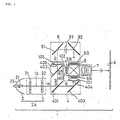
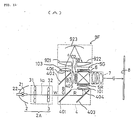
- FIG. 1 shows an optical system of a projection-type display apparatus according to a first embodiment of the present invention.
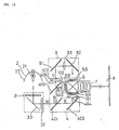
- a projection-type display apparatus 1 in this embodiment is comprised of an illumination optical system 2A constituted by a light source 2 and a uniform illumination optical device 3, a color separating optical system 4 for separating a white beam W outputted from the illumination optical system 2A through the uniform illumination optical device 3 into color beams R, G and B of red, green and blue, three liquid crystal panels 5R, 5G and 5B as light valves for modulating the color beams, a color synthesizing optical system 6 for synthesizing the modulated color beams again, and a projection lens 7 for magnifying and projecting the synthesized beam onto a screen 8.
- a light guide system 9 for guiding the green beam G among the color beams, separated by the color separating optical system 4, to the liquid crystal valve 5G.
- the light source 2 in this embodiment is constituted by a light source lamp 21 and a curved reflecting mirror 22.
- a tungsten halogen lamp, a metal halide lamp, a xenon lamp and so on can be used.
- the optical system 3 is constituted by first and second lens plates 31 and 32 arranged on a plane vertical to a center optical axis 1a thereof.
- the color separating optical system 4 is constituted by a blue/green reflecting dichroic mirror 401, a blue reflecting dichroic mirror 402 and a reflecting mirror 403.
- the blue and green beams B and G contained in the white beam W are reflected at a right angle by the blue/green reflecting dichroic mirror 401, and directed toward the blue reflecting dichroic mirror 402.
- the red beam R passes through this mirror 401, is reflected at a right angle by the reflecting mirror 403 located behind, and outputted from an outputting portion 404 for the red beam toward the color synthesizing optical system.
- the blue and green beams B and G reflected by the mirror 401 only the blue beam B is reflected at a right angle by the blue reflecting dichroic mirror 402, and outputted from an outputting portion 405 for the blue beam toward the color synthesizing optical system.
- the green beam G passed through the mirror 402 is outputted from an outputting portion 406 for the green beam toward the light guide system 9.
- the distances between the outputting portion of the uniform illumination optical device 3 for the white beam and the outputting portions 404, 405 and 406 for the color beams in the color separating optical system 4 are set to be equal.
- condenser lenses 101, 102 and 103 each of which consists of a planoconvex lens are respectively located on the outputted sides of the outputting portions 404, 405 and 406 of the color separating optical system 4 for the color beams. Therefore, the color beams outputted from the outputting portions come into the condenser lens 101-103 to be collimated.
- switching control operations are performed according to the image information by unillustrated drive means in these liquid crystal panels, thereby modulating the color beams passing therethrough.
- drive means a well-known type of drive means can be used as it is, and the explanation thereof is omitted in this embodiment.
- the green beam G is guided to the corresponding liquid crystal panel 5G through the light guide system 9, and modulated according to image information in the same manner as above.
- Each of the liquid crystal panels employed in this embodiment has a pixel pitch of less than 50 ⁇ m and uses a polysilicon TFT as a switching device.
- the light guide system 9 in this embodiment is constituted by an incident side reflecting mirror 91, an output side reflecting mirror 92 and an intermediate lens 93 located between the reflecting mirrors 91 and 92.
- the focal length of the intermediate lens 93 is set to be equal to the total optical path length of the light guide system 9.
- the focal length can be set within a range of approximately 0.9 to 1.1 times of the total optical path length of the light guide system 9.
- the distance of the green beam G is the longest, and therefore, the green beam G loses the most amount of light.
- the interposition of the light guide system 9 as in this embodiment can restrict the loss in the amount of light.
- a color beam passing through the light guide system 9 may be red or blue. However, since the amount of green light is more than those of other colors in an ordinary projection-type display apparatus, it is generally preferable to assign the green beam to the optical path passing through the light guide system 9. If brightness or evenness in image quality takes priority over color balance, it is allowable to assign the blue beam, which has a low spectral luminous efficacy and in which unevenness in luminous intensity is relatively difficult to detect, to the light guide system 9.
- the color synthesizing optical system 6 consists of a dichroic prism in this embodiment.
- a mirror composite system having dichroic mirrors arranged in the shape of X may be employed.
- each of the dichroic mirrors is an optical element which is rotationally asymmetrical about the center axis of a projection lens.
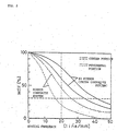
- FIG. 2 shows MTF characteristics in the projection-type display apparatus having the prism composite system in this embodiment and a projection-type display apparatus having a mirror composite system as a color synthesizing system.
- the horizontal axis indicates the spatial frequency (line/mm) representing the fineness of pixels of the display panel
- the vertical axis indicates MTF characteristics(%).
- Solid lines each indicate the characteristic of the projection optical system with the prism composite system.
- a bold solid line indicates the characteristic of the center portion of an image plane, and a thin solid line indicates that of the peripheral portion of the image plane.
- broken lines each indicate the characteristic of the projection optical system with the mirror composite system.
- a bold broken line indicates the characteristic of the center portion of the image plane, and a thin broken line indicates that of the peripheral portion of the image plane.
- the color beams are synthesized in the color synthesizing system consisting of a dichroic prism, and an optical image can be obtained and projected onto the screen 8 by the projection lens 7 under magnification.
- a lens close to a telecentric system is preferable as a projection lens.
- the uniform illumination optical device 3 consists of the first and second lens plates 31 and 32.
- the first lens plate 31 is formed from a matrix of a plurality of rectangular lenses 301
- the second lens plate 32 is similarly formed from a plurality of rectangular lenses 302.
- Each of the rectangular lenses 301 of the first lens plate 31 is shaped similarly to the liquid crystal panel to be illuminated. Images on these rectangular lenses 301 are superimposed onto the liquid crystal panel by the corresponding rectangular lenses 302 constituting the second lens plate 32. Therefore, the liquid crystal panel is illuminated with uniform illumination and little color unevenness.
- the rectangular lenses in the lens plates 31 and 32 are respectively arranged in a 4 by 3 matrix. It is preferable that the most split number of the lens plates in the vertical or horizontal direction be within a range of approximately 3 to 7. Furthermore, it is not always necessary to separate the first and second lens plates 31 and 32. These lens plates 31 and 32 can be brought closer together by making the size of each rectangular lens smaller and increasing the split number of the incident beam. Still furthermore, the lens plates 31 and 32 may be combined into a single lens plate.
- the horizontal axis indicates the split number of the first and second lens plates (integrator lenses), and the vertical axis indicates color unevenness, differences in color among the center portion (1 portion) and the peripheral portions (4 portions) on the screen 8, as differences on a U'V' chromaticity coordinate.
- a value indicated by a broken line is the largest color unevenness which is regarded as permissible as color unevenness.
- the split number be more than 3.
- the increase of the split number leads to an increase in cost from the viewpoint of production. Therefore, a practical split number is within a range of approximately 3 to 7.
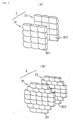
- Fig. 3(B) illustrates another arrangement example of the first and second lens plates 31 and 32 constituting the uniform illumination optical device 3.
- each of the lens plates is also constituted by rectangular lens plates of the same size.
- the split number in the vertical direction is 7.
- the split number in the horizontal direction is 3 in the top and bottom lines, 5 in the center three lines and 4 in other lines.
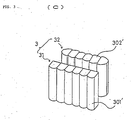
- the uniform illumination optical device 3 may be constituted by a first lens plate 31 consisting of a plurality of cylindrical lenses 301' and a second lens plate 32 consisting of a plurality of cylindrical lenses 302' as shown in Fig. 3(C).
- the luminous intensity is made uniform only in one direction, and the luminous intensity of the center of an object to be illuminated is higher than those of the cases shown in Figs. 3(A) and (B).
- the arrangement of the lenses is relatively simple, thinning of the lenses can be easily performed.
- a light emitting source close to a point source such as a tungsten halogen lamp, a metal halide lamp, a xenon lamp and so on.
- the beam emitted from the lamp is reflected by the reflecting mirror 22.
- the shape of the reflection plane of the reflecting mirror 22 may be elliptical, and in this case, a first focus is made coincident with the emitting portion of the light source lamp 21 and the second focus is made coincident with the center of the liquid crystal panel 5 (5R, 5G and 5B). As a result, the beam reflected by the reflecting mirror 22 advances toward the center of the liquid crystal panel 5.
- the size of the second lens plate 32 that is, the size of each of the rectangular lenses 302 constituting the lens plate 32 is set smaller than that of the first lens plate 31 so that the center of each rectangular lens 302 of the second lens plate 32 is positioned on a line between the center of each corresponding rectangular lens 301 of the first lens plate 31 and the center of the liquid crystal panel 5.
- Each of the rectangular lenses 301 of the first lens plate 31 condenses the beam onto the center of the corresponding rectangular lenses 302 of the second lens plate 32.
- the rectangular lenses 302 of the second lens plate 32 superimpose images on the corresponding rectangular lenses 301 of the first lens plate 31 onto a display area 5A (an area diagonally shaded in the figure) of the liquid crystal panel 5. Since the image in the outputting portion of the light source lamp 21 is thus formed on the center of each rectangular lens 302 of the second lens plate 32, the whole second lens plate 32 functions as a secondary light source.
- a chief ray 303 of a beam incident on the end of the display area 5A of the liquid crystal panel 5 coincides with a line which links the center of the second lens plate 32 and the end of the display area 5A.
- the illumination beam to the liquid crystal panel 5 is an diverged beam from the second lens plate 32, it is necessary to collimate the diverged beam in order to make a collimated beam incident on the liquid crystal panel 5.
- the condenser lenses 101, 102 and 103 are arranged in this embodiment.
- the focal length of each condenser lens is set equal to a distance b between the second lens plate 32 and the condenser lens.
- a planoconvex lens which is located with a convex plane facing the liquid crystal panel 5 is used as the condenser lens.
- the convex plane may be set to face the second lens plate 32.
- a double-convex lens or a Fresnel lens may be used instead of the planoconvex lens.
- the chief ray of the beam outputted through the liquid crystal panel 5 is made parallel to the center axis 1a of the whole illuminatio n optical system by arranging the condenser lenses 101, 102 and 103.
- Fig. 5(B) illustrates a variation of the illumination optical system.
- a parabolical plane is used as a reflection plane of the reflecting mirror 22 of the light source 2. Since the focus of the parabolical plane is made coincident with the emitting portion of the light source lamp 21 in this case, a beam reflected by the reflecting mirror 22 is almost parallel to the center axis 1a of the illumination system. Therefore, the uniform illumination optical device 3 used in this case is constituted by first and second lens plates 31' and 32' of the same size, and rectangular lenses constituting the lens plates each have the same focal length. Rectangular lenses 302' of the second lens plate 32' form an image on corresponding rectangular lenses of the first lens plate 31' at an infinite distance.
- a lens 306 is added in this case in order to form the image to be formed at an infinite distance onto the display area 5A of the liquid crystal panel 5.
- the focal length of the lens 306 is set to be equal to the distance between the lens 306 and the liquid crystal panel 5.
- the lens 306 may be integrally formed with the second lens plate 32.
- the distance between the lens plates 31 and 32 can be relatively long, and a reflecting mirror 33 can be interposed between the lens plates 31 and 32 as shown in Fig. 13.
- the volume of the uniform illumination optical system is almost a half of that in the above embodiment.
- all the optical systems can be arranged in an area close to a square as shown in the figure, and it contributes to downsizing of the whole apparatus.
- the light guide system 9 in this embodiment is constituted by the two reflecting mirrors 91 and 92 and the intermediate lens 93 located therebetween. Another arrangement of the light guide system applicable to this embodiment will now be described below.
- a light guide system 9A shown in Fig. 6 has the arrangement obtained by omitting the intermediate lens 93 from the light guide system 9 in this embodiment.
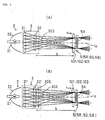
- a light guide system 9B shown in Fig. 7(A) has the arrangement in which an incident lens 94 is added on the incident side thereof and an outputting lens 95 is added on the output side thereof besides the arrangement of the light guide system 9 in this embodiment.
- the intermediate lens 93 is located just at the center of the whole optical path of the light guide system 9B, and when it is assumed that the total optical path length is 2a, the focal length of the intermediate lens 93 is set to be almost equal to a/2. Therefore, the intermediate lens 93 forms an image of an object 96 on the incident side of the light guide system 9B onto the output side thereof as a reversed image 97. In other words, the illumination distribution on the incident side is transferred with an 180-degree turn on the emission side.
- the illumination optical system provided with the uniform illumination optical device 3 is employed in this embodiment, the illumination distribution is almost symmetrical about the 180-degree turn. Therefore, even if the illumination distribution is turned or reversed, no color unevenness arises on the display.
- the incident lens 94 has a focal length which equals a distance a to the intermediate lens 93, and directs a main ray 9a of the beam G collimated through the condenser lens 103 toward the center of the intermediate lens 93. Therefore, an image on the second lens plate 32 on the output side of the uniform illumination optical device 3 is formed in the center of the intermediate lens 93. Furthermore, the outputting lens 95 also has a focal length set to be equal to a, and collimates and outputs the chief ray of the diverged beam outputted from the center of the intermediate lens 93.
- the incident lens 94 is, as shown in the figure, a planoconvex lens, and is located with a convex side thereof facing the incident side, thereby decreasing its spherical aberration.
- the output lens 95 is also a planoconvex lens located with a convex side thereof facing on the output side.
- the focal lengths of the incident lens 94 and the output lens 95 be each set within a range of approximately 0.5 to approximately 0.7 times of the total optical path length (2a) of the light guide system 9B.
- the focal length of the intermediate lens 93 be a little longer than 1/4 of the total optical path length (2a), and be set within a range of approximately 0.25 to approximately 0.4 times of the total optical path length.
- Fig. 8(A) illustrates a variation of the above-mentioned light guide system 9B.
- a lens 97 made by integrally forming the incident lens 94 and the condenser lens 103 located on this side in the direction of the optical path in the light guide system 9B.
- the focal length of the lens 97 is set at a value obtained by adding the refracting powers of the incident lens 94 and the condenser lens 103, in short, ab/(a+b) as shown in Fig. 8(B). It is preferable that the lens 97 be a double-convex lens in order to reduce spherical aberration.
- the intermediate lens 93 is constituted by two planoconvex lenses 931 and 932.
- the focal length of each of the planoconvex lenses 931 and 932 is set at a.
- Fig. 9 illustrates a variation of the light guide system 9C.
- an aspherical lens 98 is employed instead of the integrated lens 97 in the above light guide system 9C.
- the use of the aspherical lens makes spherical aberration even smaller than that in use of the double-convex lens. Therefore, the illumination distribution on the incident side of the light guide system can be transferred to the output side with extreme precision.
- the employed illumination optical system is provided with the uniform illumination optical device 3, and a dichroic prism, which is an axially symmetrical optical device, is used as the color synthesizing optical system. Therefore, it is possible to realize a projection-type display apparatus in which unevenness in color and luminous intensity is small and the illumination efficiency is high. Furthermore, since the color synthesizing system including a dichroic prism is used, the focal length of the projection lens can be shortened, and a large-scale display at a short distance can be performed. Consequently, the application of the constitution of this embodiment to a rear projector makes it possible to shorten the depth of the projector, and to make the projector compact.
- the focal lengths of the intermediate lens, the incident lens and the outputting lens which are optical devices constituting the light guide system, are set at proper values, it is possible to decrease the occurrence of color unevenness and the loss in the amount of light of the color beams passing through those optical devices, thereby restricting unevenness in color and luminous intensity of a projection image, and forming a bright image.
- the optical system can be compact and inexpensive. If the integrated lens is replaced with an aspherical lens, it is possible to make the optical system compact and reduce spherical aberration.
- the split number in the uniform illumination optical device is set within a range of 3 to 7 and the pixel pitch of the liquid crystal panel is set less than 50 ⁇ m, color unevenness, blurring and so on of the projection image can be restricted. Therefore, it is possible to realize a projection-type display apparatus capable of forming a projection image of high quality.
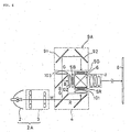
- FIG. 10 illustrates a projection-type display apparatus according to a second embodiment of the present invention.
- a projection-type display apparatus 100 in this embodiment is the same as the above-mentioned projection-type display apparatus 1 in the first embodiment except for the structure of a light guide system. Therefore, like components are denoted by like numerals, and the explanation thereof is omitted.
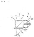
- a light guide system 9E in the projection-type display apparatus 100 of this embodiment is constituted by an incident side triangular prism 901, an output side triangular prism 902 and a quadratic prism 903 located between the triangular prisms 901 and 902.
- the total reflection plane 905 may be an optical flat surface merely made of glass or plastic. However, if the incident beam includes a light beam of an angle which is not totally reflected, it is preferable that the total reflection plane 905 be coated with a metal film, such as aluminum, silver and so on. Instead, coating with a dielectric multilayer reflective film may be conducted.
- the incident plane 904 and the outputting plane 906 serve to guide light by the total reflection as illustrated, each of them is needed to be an interface between air and the glass material and cannot be contact with adjacent optical elements. Therefore, it is necessary that five planes of the triangular prism 901 are all optical flat planes and, in some cases, the incident plane 904 and the outputting plane 906 thereof are required to be applied with a reflection attenuation coating. Particularly, it is preferable that a non-reflection coating be conducted on the interface between the triangular prism 901 and the adjacent triangular prism 903.
- Six planes of the quadratic prism 903 are all optical flat planes, and four planes 907 parallel to a main axis of the beam passing therethrough guide the light beam by total reflection.
- the triangular prism 902 on the output side of the quadratic prism 903 has the same structure as that of the triangular prism 901 on the incident side.
- the emitted beam enters the display area 5A of the liquid crystal panel 5G.
- the shape of the incident surface 904 of the triangular prism 901 and the shape of the emitting plane of the triangular prism 902 are almost the same as the rectangular shape of the display area 5A of the liquid crystal panel 5G.
- a uniform illumination optical device 3 of the illumination optical system is, as shown in Fig. 3, constituted by first and second lens plates 31 and 32 in each of which rectangular lenses are arranged in a matrix. Therefore, the incident surface 904 of the incident side triangular prism 901 is almost uniformly illuminated in relation to the rectangular shape thereof.
- the three prisms transfer the incident beam to the display area 5A of the liquid crystal panel 5G while keeping the amount of light, the collimated state and uniform brightness distribution of the incident beam. Though it is necessary to locate the triangular prism 902 on the output side and the liquid crystal panel 5G close to each other, if there is a distance which cannot be ignored, a prism or a lens for light guiding may be additionally located.
- the same advantage as that of the above-mentioned first embodiment can be obtained by the projection-type display apparatus having such constitution in this embodiment.
- a cylindrical light guide member formed from the combination of four reflecting mirrors may be employed.
- the quadratic prism 903 shown in Fig. 10(B) may be replaced with a cylindrical light guide system constituted by four reflectivity mirrors 903' shown in Fig. 10(C). Though the reflectance of light guide surfaces is a little lowered, the operation is not changed.
- the light guide system may be constituted by two upper and lower reflecting plates 911 and 912 and two reflecting mirrors 913 and 914 for folding the optical path. In this case, though the incident beam cannot be transferred without any loss in the amount of light, the loss amount can be reduced by shortening the focal length of the lens 103 to some extent. Since the illumination distribution cannot be also kept, this method is suited to the uniform illumination optical device using the cylindrical lenses shown in Fig. 3(C).
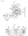
- FIG. 14(A) illustrates a projection-type display apparatus according to a third embodiment of the present invention.
- a projection-type display apparatus 500 in this embodiment is the same as the above-mentioned one of the first embodiment except for the structure of a light guide system thereof. Therefore, like components are denoted by like numerals, and the explanation thereof is omitted.
- a light guide system 9F in the projection-type display apparatus 500 of this embodiment is constituted by a field lens 921 on the incident side, a field lens 922 on the output side and a concave mirror 923.
- a condenser lens 103 adjacent to the incident portion of the light guide system 9F and the field lens 921 may be combined into a single lens.
- a light guide system 9G having such structure is illustrated in Fig. 14(B).
- An integrally formed lens 924 consists of a decentered double-convex lens as illustrated.
- a concrete structure of the above-mentioned light guide system 9F is shown in fig. 15(A). If it is assumed that a distance between the concave mirror 923 located in the center of the optical path and the field lens 921 or 922 is a, the focal length of the concave mirror 923 is almost equal to a/2.
- the curved surface of the concave mirror 923 is spherical or elliptical. Therefore, the concave mirror 923 forms image of an object 802 in the incident portion into the emitting portion as a reflected image 803, and in fact, the illumination distribution in the incident portion is reversed and outputted in the emitting portion.
- the field lenses 921 and 922 each have a focal length equal to a, and optical axes 801 thereof coincide with each other in the center therebetween.
- the incident side field lens 921 focuses a collimated beam from the condenser lens 103 onto the center of the concave mirror 923.
- the output side field lens 922 refracts the reflected beam from the concave mirror 923 so as to be perpendicular to a liquid crystal panel 5G.
- the light guide system 9F may be structured as shown in Fig. 15(B).
- a light guide system 9H shown in the figure two field lenses 921 and 922 in the above light guide system 9E are replaced by a single lens 806, the concave mirror 923 is replaced by a plane mirror 804 which is located at a distance of a/2 from the lens 806.
- a plane mirror 805 is arranged perpendicular to an optical axis 807 of the lens 806.
- a collimated beam incident on the light guide system 9H is reflected by the plane mirror 804 through an end portion of the lens 806, and focused onto the center of the plane mirror 805.
- the beam reflected by the plane mirror 805 is reflected by the plane mirror 804, passes through an end portion of the lens 806, and perpendicularly enters a display area 5A of a liquid crystal panel 5G.
- An image of an object 802 on the incident side is formed as a reflected image 803 by the center of the lens 806. Since the beam passes through the center of the lens 806 twice, it is the same as the case the beam passes through a lens having a focal length of a/2.
- the constitution of this embodiment has an advantage in making the size of the apparatus smaller than that in use of the above-mentioned light guide system 9F.
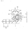
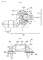
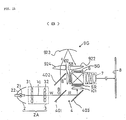
- Fig. 11 illustrates a projection-type display apparatus according to a fourth embodiment of the present invention.
- a projection-type display apparatus 200 in this embodiment is contrived so as to compactly house an optical system in a case 201.
- the optical system in this embodiment is constituted by an illumination optical system 2B, a color separating optical system 4, light valves 5R, 5G and 5B, a color synthesizing optical system 6, a projection lens 7 and a light guide system 9D.
- the color separating optical system 4, the light valves 5R, 5G and 5B, the color synthesizing optical system 6 and the projection lens 7 are the same as those in the apparatus 100 of the first embodiment.
- the light guide system 9D is the same as that shown in Fig. 9(A). Therefore, components corresponding to the above-mentioned ones are denoted by like numerals, and the explanation thereof is omitted.
- the direction of an emitted beam from a light source lamp 21 is folded at a right angle in the illumination optical system 2B so that a center axis of a beam emitted from the illumination optical system 2B is parallel to an optical axis 7a of the projection lens 7.
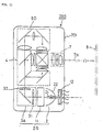
- the illumination optical system 2B is provided with a polarized beam conversion system 11.
- the illumination optical system 2B in this embodiment is constituted by a light source 2 composed of the lamp 21 and a reflecting mirror 22, the polarized beam conversion device 11 located on the emission side of the light source 2, and a uniform illumination optical device 3A on the emission side of the polarized beam conversion device 11.
- the polarized beam conversion device 11 in this embodiment is constituted by a polarizing beam splitter 111, a reflecting mirror 112, and a _/2 phase plate 113.
- a random polarized beam 114 emitted from the light source 2 is separated into two linearily polarized beams, a P polarized beam 115 and an S polarized beam 116, by the polarizing beam splitter 111 which is a polarized beam separating element. Since the polarized beam separating function of the polarizing beam splitter 111 has a dependence on an incident angle, a light source provided with a lamp having a short arc length and capable of emitting a beam excellent in parallelism is suitable.
- the separated P polarized beam 115 passes through the _/2 phase plate 113 which is a polarizing plane rotating element, a polarization plane thereof is turned at an angle of 90° and the P polarized beam 115 is converted into an S polarized beam.
- the S polarized beam 116 is outputted as it is while an optical path thereof is merely folded by the prismatic reflecting mirror 112.
- the reflecting mirror 112 is made of, for example, an aluminum evaporated film. Since the reflecting mirror 112 has a higher reflectivity rate for an S polarized beam than that for a P polarized beam, the optical path of the S polarized beam is folded by the reflecting mirror 112.
- an ordinary plane reflecting mirror may be used instead of such prismatic mirror.
- the random polarized beam 114 from the light source is outputted as an S polarized beam by passing through the polarized beam conversion device 11 having such structure.
- the P polarized beam is converted into the S polarized beam in this embodiment, to the contrary, it is allowable that the S polarized beam is converted into a P polarized beam, and the P polarized beam is emitted from the polarized beam conversion device 11.
- the uniform illumination optical device 3A located on the output side of the polarized beam conversion device 11 is constituted by a first lens plate 31 located on a plane perpendicular to the chief axis of the outputted S polarized beam 116, a second lens plate 32 orthogonal to the first lens plate 31, and a reflecting mirror 33 located between the lens plates 31 and 32 for folding the optical path at a right angle.
- the first and second lens plates each have the same structure as that in the first embodiment.
- the light beam incident on the uniform illumination optical device 3A is thus folded at a right angle and outputted.
- the outputted white s polarized beam is separated into beams of primary colors by the color separating optical system 4.
- the separated color beams are synthesized by the color synthesizing optical system 6 consisting of a dichroic prism, and magnified and projected onto a screen 8 through the projection lens 7 under magnification.
- the optical path is formed in the apparatus 200 of this embodiment so that the direction of the projection beam is parallel and reverse to the emission direction of the illumination optical system 2B, and a cooling fan 12 for restricting heat generation of the light source lamp 21 is located on the back side of the light source 2 in the case 201.
- the illumination optical system 2B is provided with the polarized beam conversion device 11. Therefore, the random polarized beam emitted from the light source is converted into two specific linearily polarized beams, and the converted beams are efficiently superposed and output with little loss incident to the emission. That can realize a bright illumination optical system capable of outputting only polarized beams at high efficiency. Furthermore, since the outputted polarized beams pass through the uniform illumination optical device 3A in this embodiment, unevenness in color and luminous intensity caused in the light source is restricted and illumination light of high uniformity can be obtained.
- an illumination optical system has a uniform illumination optical device
- a color synthesizing system has a dichroic prism
- a light guide system is located on the optical path of a color beam having the longest optical path length in a color separating system
- emitted color beams separated through the color separating system are collimated by condenser lenses and applied onto light valves. Therefore, according to the present invention, unevenness in color and luminous intensity of light from a light source is restricted by the uniform illumination optical device.
- the color synthesizing system is a prism composite system which causes less unevenness in color and luminous intensity than a mirror composite system, and therefore, the unevenness in color and so on hardly arises therein.
- the loss in the amount of light is small and the illumination efficiency is enhanced. Therefore, according to the present invention, it is possible to realize a projection-type display apparatus which causes less unevenness in color and luminous intensity than ever and has a high illumination efficiency.
- the focal lengths of lenses which are components of the light guide system, are set at appropriate values, or a prism is used as the light guide system. According to this constitution, since unevenness in color and loss in the amount of light in the light guide system can be restricted, it is possible to form a projection image having little unevenness in color and a high illumination efficiency.
- a dichroic prism which is an element rotationally symmetrical about the center axis of the projection optical system, is used as the color synthesizing system, and a liquid crystal panel having a small pixel pitch of less than approximately 50 ⁇ m is used as a light valve. Therefore, according to the present invention, it is possible to form a projection image of high resolution and to downsize the whole apparatus by employing a liquid crystal panel using a polysilicon TFT or the like which is easy to make compact.
- the split number of the lens plates constituting the uniform illumination optical device is set within a range of 3 to 7 in the present invention, it is possible to form a projection image whose unevenness in color is restricted.
- the illumination optical system is provided with a polarized beam conversion device in the present invention, it is possible to restrict the emission loss of the light emitted from the light source lamp, and therefore, to form a bright projection image.
- the optical path is formed in the projection-type optical system of the present invention so that the projection light can be outputted in the direction reverse and parallel to the onward direction of the light beam emitted from the illumination optical system, and a cooling means for the light source lamp is located on the output side of the projection light in the apparatus case.
- the cooling means is located on the reverse side to a viewer of the projection image, and air from the cooling means is exhausted to the reverse side to the viewer. Therefore, it is advantageous in preventing the noise and exhausted air from the cooling means from disturbing the viewer.
- a back focus of the projection lens of the optical system is short, a large-scale projection at a short distance is easy to perform. Therefore, it is possible to realize a projection-type display apparatus suitable for presentation use and home theater use. Furthermore, since the back focus of the projection lens is short, it is possible to realize a projection lens having a small F number by a small number of lenses, and therefore, to lower the production cost of the apparatus.
Abstract
Description
- The present invention relates to a projection-type display apparatus which separates a white beam from a light source into beams of three colors, red, blue and green, modulates these beams through light valves according to image information, and re-synthesizes and projects the modulated beams under magnification onto a screen through a projection lens.
- A projection-type display apparatus is comprised of a light source lamp, a color separating means for separating a white beam from the light source lamp into beams of three colors, three light valves for modulating the separated color beams, a color synthesizing means for synthesizing the modulated beams again, and a projection lens for magnifying and displaying a light image obtained by the synthesis onto a screen. As light valves, liquid crystal panels are generally used.
- A conventional projection-type display apparatus having such structure in which a uniform illumination optical device referred to as an optical integrator is incorporated in a light source thereof is well known. For example, U. S. Patent No. 5,098,184 discloses a projection-type display apparatus having such optical integrator incorporated therein. This patent publication also discloses a color synthesizing means consisting of dichroic mirrors arranged in the shape of X. An ordinary color synthesizing means is constituted by dichroic mirrors each of which has a dielectric multilayer film on a glass plate.
- Such projection-type display apparatus provided with a mirror composite system in which a color synthesizing means is constituted by dichroic mirrors has the following disadvantage. Each dichroic mirror is an optical element which is rotationally asymmetrical about the center axis of a projection lens. Therefore, astigmatism arises in an image on the screen, and Modulation Transfer Function (MTF) representing the transfer characteristic of a projection optical system is lowered. As a result, the image is blurred and sharpness thereof is reduced. In a case in which the size of a liquid crystal panel is large relative to the number of pixels, in other words, when the pixel pitch is large, the lowering of the MTF does not cause such a large problem. However, when the pixel pitch is small, for example, as in a liquid crystal panel using a polysilicon TFT as a switching device, such lowering cannot be ignored.
- Furthermore, a conventional projection-type display apparatus having a prism composite system in which a color synthesizing means consists of a dichroic prism is well known. The dichroic prism is an optical element which is rotationally symmetrical about the center axis of a projection lens. Therefore, astigmatism caused by this prism can be easily removed by the design of the projection lens, and the MTF of the projection-type display apparatus having such a prism composite system is generally superior to that of the above-mentioned display apparatus having the mirror composite system. Accordingly, such apparatus is suitable in the case in which a liquid crystal panel having a small pixel pitch is used as a light valve.
- Another type of conventional projection-type display apparatus is disclosed in, for example, U.S. Patent No. 4,943,154. In this apparatus, the decrease in the amount of light and the unevenness in color are restricted by equalizing the optical path lengths (the distances between a light source and liquid crystal panels) of beams of three colors in a color separating means. In other words, a light transmitting means constituted by a relay lens, a field lens and so on is interposed on an optical path of the beam having the longest optical path length in the apparatus disclosed in the specification of this patent, thereby optically equalizing the optical path lengths of the color beams.
- However, in this apparatus, while the light amount of the color beam having the longest optical path length is not reduced, the brightness distribution thereof is made to do a complete about-face by the relay lens. Therefore, if the initial brightness distribution is not axially symmetrical, color unevenness arises in the display on a screen, and the quality of the display is degraded. Though such color unevenness does not arise if the brightness distribution of the beam is axially symmetrical, in fact, the brightness distribution is normally made axially asymmetrical by the displacement of an attachment position of a light source lamp and the slight asymmetrical properties of the light source lamp and a reflecting mirror.
- In a projection-type display apparatus, it is desirable to increase the luminous intensity of an image to be projected, and to obtain an image quality close to that of the image directly viewed on a CRT without unevenness in color and luminous intensity. For such purpose, it is preferable to use a prism composite system having a good transfer characteristic as a color synthesizing system. It is also preferable to efficiently illuminate a liquid crystal panel with uniform brightness by using an optical integrator in a light source portion. However, if the optical integrator is used as it is in a case in which the optical path lengths of the beams in the color separating system are different, the decrease in the amount of light and change of brightness distribution of the beam having the longest optical path are remarkable, which results in color unevenness and a change in color temperature of a projected image. Therefore, a sufficient effect of the integrator cannot be shown. Furthermore, when the optical integrator is used in the light source portion, the conventional art cannot be utilized as it is. In other words, since a diverged beam from a plane light source which exists in a finite position (a beam outgoing plane of the integrator) from the liquid crystal panel illuminates the liquid crystal panel, the illumination with the optical integrator is basically different from the illumination from a point light source existing at an infinite distance from the liquid crystal panel as in the arrangement of the conventional art.
- An object of the present invention is to provide a projection-type display apparatus which can generate a projection image of higher quality, compared with the above-mentioned conventional projection-type display apparatus, without any unevenness in luminous intensity and color.
- Another object of the present invention is to provide an inexpensive projection-type display apparatus which can generate a projection image of high quality.
- Still another object of the present invention is to provide a projection-type display apparatus which can generate a projection image having higher luminous intensity than a conventional one.
- A further object of the present invention is to provide a compact projection-type display apparatus which can generate a projection image of high quality.
- A still further object of the present invention is to provide a projection-type display apparatus suited to be used for front projection.
- In order to achieve the above objects, the present invention provides a projection-type display apparatus comprising a light source, a color separating means for separating a white light beam emitted from the light source into beams of three primary colors, three light valves for modulating the separated color beams, a light guide means located on an optical path of one color beam having the longest optical path length among the color beams separated by the color separating means and respectively incident on the three light valves, a color synthesizing means for synthesizing the color beams modulated through the light valves, and a projection lens for projecting the synthesized and modulated beam onto a screen, wherein there are provided a uniform illumination optical means interposed on an optical path between the light source and the color separating means so as to convert the white beam from the light source into a uniform rectangular beam and outputting the beams toward the color separating means, and three condenser lenses located respectively in outputting portions of the color separating means for emitting the color light beams to convert the diverged beams outputted from the uniform illumination optical means into almost collimated beams, and wherein the color synthesizing means consists of a dichroic prism, and the light guide means is constituted by an incident side reflecting mirror, an output side reflecting mirror, and at least one lens.
- In the projection-type display apparatus of the present invention having such constitution, the light valves are illuminated by the uniform illumination means, the diverged color beams are collimated by the condenser lenses respectively located on the optical paths of the color beams, and the optical path lengths of the color beams are optically equalized by making one of the color beams pass through the light guide system. Therefore, according to the present invention, it is possible to form a projection image with uniform illumination distribution and little color unevenness, and more brightness and higher quality than ever.
- It is preferable that the light guide means have one intermediate lens, and the focal length of the intermediate lens be set within a range of approximately 0.9 to 1.1 times of the optical path length of the light guide means.
- The light guide means may also comprise an incident lens located in the incident side of the incident side reflecting mirror, an output lens located on the output side of the output side reflecting mirror, and an intermediate lens located between the incident and output side reflecting mirrors. In this case, it is preferable that the focal lengths of the incident and output side lenses each be set between approximately 0.5 to 0.7 times of the optical path length of the light guide means and the focal length of the intermediate lens be set between approximately 0.25 and 0.4 times of the optical path length of the light guide means so as to restrict any aberration.
- Furthermore, in this case, the optical system can be made compact by combining the above incident lens and the above condenser lens for making the collimated beam incident on the incident lens into a single lens, and that is preferable. If the single lens is employed, it is preferable that the lens be an aspherical lens in order to restrict aberration in the periphery thereof.
- Liquid crystal panels are available as the above-mentioned light valves. In this case, it is preferable that resolution of a projection image be enhanced by setting a pixel pitch of each liquid crystal panel at less than approximately 50µm.
- On the other hand, the uniform illumination optical system may be provided with at least one lens plate consisting of a plurality of lenses arranged in a plane perpendicular to the chief axis of the light emitted from the light source lamp. In this case, it is preferable that the split number of the lens plate in one direction be set between approximately 3 to 7.
- A green light beam whose amount of light is normally larger than that of other color beams, or a blue light beam in which the influence on an image quality caused by change in the amount of light is relatively difficult to detect is preferable as a color beam to be passed through the above light guide means.
- The uniform illumination optical system may be constituted by a first lens plate, a second lens plate and a reflecting mirror interposed between the lens plates, and the optical path thereof may be folded, for example, at a right angle.
- Furthermore, it is preferable that a polarized beam conversion means be located between the light source lamp and the uniform illumination optical means. The polarized beam conversion means is constituted by a polarized beam separating element for separating a random polarized beam from the light source lamp into two linearily polarized beams of P and S beams, and a polarization plane rotating means for rotating a polarization plane of one of the two separated and polarized beams at an angle of 90° so as to coincide with that of the other linearily polarized beam. Since the use of the polarized beam conversion means makes it possible to enhance the use efficiency of light emitted from the light source lamp, the luminous intensity of a projection image can be increased.
- The projection-type display apparatus of the present invention is characterized in that the above light guide system is provided with an incident side triangular prism located on the incident side for folding an optical path at a right angle, an output side triangular prism located on the output side for folding the optical path at a right angle, and a light guide member located between these triangular prisms. Even in the projection-type display apparatus having such constitution, it is possible to form a projection image with uniform illumination distribution and little color unevenness and having more brightness and higher quality than ever.
- As the light guide member, a quadratic prism may be used. It is preferable that interfaces of the triangular prism and the quadratic prism be covered with a anti-reflective coating. Furthermore, it is preferable that a total reflection surface of each triangular prism be coated with a metal film or a dielectric multilayer film.
- Another projection-type display apparatus of the present invention is suited to be used as a front projector, and characterized in that there are provided a light source, a color separating means for separating a white light beam emitted from the light source into beams of three primaty colors, three light valves for modulating the separated color beams, a light guide means located on the optical path of the color beam having the longest optical path length among the color beams separated by the color separating means and respectively incident on the three light valves, a color synthesizing means for synthesizing the color beams modulated through the light valves, and a projection lens means for projecting the synthesized and modulated beam onto a screen, and further comprising a uniform illumination optical means located on an optical path between the light source and the color separating means for converting the white beam from the light source into a uniform rectangular beam and emitting the beam into the color separating means, and three condenser lenses located respectively in emitting portions of the color separating means for emitting the color light beams so as to convert the diverged beam outputted from the uniform illumination optical means into almost collimated beams, wherein the color synthesizing means is constituted by a dichroic prism, the light guide means consists of an incident side reflecting mirror, an output side reflecting mirror, and at least one lens, the optical path is formed so that the direction of the beam from the projection lens is parallel and reverse to the onward direction of the light beam emitted from the light source, a cooling means for the light source is located on the output side of the projection light in an apparatus case, and a vent of the cooling means is formed on a side surface of the case on the output side of the projection light.
- According to such constitution, since the cooling means is located on the reverse side to a viewer of a projection image, it is advantageous in preventing noises and exhausted air from the cooling means from disturbing the viewer.
-
- Fig. 1 is a schematic view showing a general constitution of a projection-type display apparatus according to a first embodiment of the present invention;
- Fig. 2 is a graph showing relations between the pixel density and the transfer characteristic (MTF) of a liquid crystal panel used as a light valve in the projection-type display apparatus;
- Figs. 3 (A), (B) and (C) each are a schematic perspective view showing the structure of first and second lens plates constituting a uniform illumination optical device shown in Fig. 1;
- Fig. 4 is a graph showing the relation between the split number of the lens plates of the uniform illumination optical device and color unevenness;
- Figs. 5(A) and (B) each are a view explaining the operation of the uniform illumination optical device;
- Fig. 6 is a schematic structure view showing a variation of a light guide system in the first embodiment of the present invention;
- Figs. 7(A) and (B) are respectively a schematic structure view showing another variation of the light guide system in the first embodiment of the present invention, and an explanatory view of the operation thereof;
- Figs. 8(A) and (B) are respectively a schematic structure view showing a further variation of the light guide system in the first embodiment of the present invention, and an explanatory view of the operation thereof;
- Fig. 9 is a schematic structure view showing a variation of the light guide system shown in Fig. 8(A);
- Figs. 10(A) and (B) are respectively a schematic structure view showing an optical system in a projection-type display apparatus according to a second embodiment of the present invention, and an explanatory view showing a light guide system therein, and Figs. 10(C) and (D) each are explanatory views showing variations of the light guide system shown in Fig. 10(B);
- Fig. 11 is a schematic structure view showing an optical system and a cooling fan of a projection-type display apparatus according to a fourth embodiment of the present invention;
- Fig. 12 is an explanatory view showing the structure of a polarized beam conversion device incorporated in the illumination optical system shown in Fig. 11;
- Fig. 13 is a schematic structure view showing a variation of the uniform illumination optical device shown in Fig. 1;
- Figs. 14(A) and (B) are schematic structure views showing a projection-type display apparatus according to a third embodiment of the present invention and a variation thereof; and
- Fig. 15(A) is an explanatory view of a light guide system shown in Fig. 14(A) and Fig. 15(B) is an explanatory view of a variation of the light guide system shown in Fig. 15(A).
-
- Embodiments of the present invention will be described below in reference to the drawings.
- Fig. 1 shows an optical system of a projection-type display apparatus according to a first embodiment of the present invention. A projection-
type display apparatus 1 in this embodiment is comprised of an illuminationoptical system 2A constituted by alight source 2 and a uniform illuminationoptical device 3, a color separatingoptical system 4 for separating a white beam W outputted from the illuminationoptical system 2A through the uniform illuminationoptical device 3 into color beams R, G and B of red, green and blue, threeliquid crystal panels optical system 6 for synthesizing the modulated color beams again, and aprojection lens 7 for magnifying and projecting the synthesized beam onto ascreen 8. There is also provided alight guide system 9 for guiding the green beam G among the color beams, separated by the color separatingoptical system 4, to theliquid crystal valve 5G. - The
light source 2 in this embodiment is constituted by alight source lamp 21 and a curved reflectingmirror 22. As thelight source lamp 21, a tungsten halogen lamp, a metal halide lamp, a xenon lamp and so on can be used. Though the details of the uniform illuminationoptical system 3 will be described below, theoptical system 3 is constituted by first andsecond lens plates optical axis 1a thereof. - The color separating
optical system 4 is constituted by a blue/green reflectingdichroic mirror 401, a blue reflectingdichroic mirror 402 and a reflectingmirror 403. The blue and green beams B and G contained in the white beam W are reflected at a right angle by the blue/green reflectingdichroic mirror 401, and directed toward the blue reflectingdichroic mirror 402. The red beam R passes through thismirror 401, is reflected at a right angle by the reflectingmirror 403 located behind, and outputted from an outputtingportion 404 for the red beam toward the color synthesizing optical system. As for the blue and green beams B and G reflected by themirror 401, only the blue beam B is reflected at a right angle by the blue reflectingdichroic mirror 402, and outputted from an outputtingportion 405 for the blue beam toward the color synthesizing optical system. The green beam G passed through themirror 402 is outputted from an outputtingportion 406 for the green beam toward thelight guide system 9. In this embodiment, the distances between the outputting portion of the uniform illuminationoptical device 3 for the white beam and the outputtingportions optical system 4 are set to be equal. - In this embodiment,
condenser lenses portions optical system 4 for the color beams. Therefore, the color beams outputted from the outputting portions come into the condenser lens 101-103 to be collimated. - The red and blue beams R and B among the collimated color beams R, G and B come into the
liquid crystal panels condenser lenses liquid crystal panel 5G through thelight guide system 9, and modulated according to image information in the same manner as above. Each of the liquid crystal panels employed in this embodiment has a pixel pitch of less than 50µm and uses a polysilicon TFT as a switching device. - The
light guide system 9 in this embodiment is constituted by an incidentside reflecting mirror 91, an outputside reflecting mirror 92 and anintermediate lens 93 located between the reflecting mirrors 91 and 92. In this embodiment, the focal length of theintermediate lens 93 is set to be equal to the total optical path length of thelight guide system 9. The focal length can be set within a range of approximately 0.9 to 1.1 times of the total optical path length of thelight guide system 9. Among the optical path lengths of the color beams, that is, the distances between thelight source lamp 21 and the liquid crystal panels, the distance of the green beam G is the longest, and therefore, the green beam G loses the most amount of light. However, the interposition of thelight guide system 9 as in this embodiment can restrict the loss in the amount of light. Therefore, the optical path lengths of the color beams can be substantially equalized. A color beam passing through thelight guide system 9 may be red or blue. However, since the amount of green light is more than those of other colors in an ordinary projection-type display apparatus, it is generally preferable to assign the green beam to the optical path passing through thelight guide system 9. If brightness or evenness in image quality takes priority over color balance, it is allowable to assign the blue beam, which has a low spectral luminous efficacy and in which unevenness in luminous intensity is relatively difficult to detect, to thelight guide system 9. - Then, the color beams modulated by the respective
liquid crystal panels optical system 6 to be synthesized again. The color synthesizingoptical system 6 consists of a dichroic prism in this embodiment. As the color synthesizing optical system, a mirror composite system having dichroic mirrors arranged in the shape of X may be employed. However, in a projection-type display apparatus provided with such color synthesizing system which has a mirror composite system constituted by dichroic mirrors, each of the dichroic mirrors is an optical element which is rotationally asymmetrical about the center axis of a projection lens. Therefore, astigmatism arises in an image on a screen, and Modulation Transfer Function (MTF) of a projection optical system is lowered. As a result, the image is blurred and sharpness thereof is reduced. However, in a case in which the size of a liquid crystal panel is large relative to the number of pixels, in other words, when the pixel pitch is large, the lowering of the MTF does not cause such a large problem. However, when the pixel pitch is small in a case of a liquid crystal panel using a polysilicon TFT as a switching device as in this embodiment, such lowering cannot be ignored. Since the dichroic prism is used as the color synthesizingoptical system 6 in this embodiment, such a bad effect can be avoided. - That point will now be described with reference to Fig. 2. This figure shows MTF characteristics in the projection-type display apparatus having the prism composite system in this embodiment and a projection-type display apparatus having a mirror composite system as a color synthesizing system. Referring to the figure, the horizontal axis indicates the spatial frequency (line/mm) representing the fineness of pixels of the display panel, and the vertical axis indicates MTF characteristics(%). Solid lines each indicate the characteristic of the projection optical system with the prism composite system. A bold solid line indicates the characteristic of the center portion of an image plane, and a thin solid line indicates that of the peripheral portion of the image plane. Similarly, broken lines each indicate the characteristic of the projection optical system with the mirror composite system. A bold broken line indicates the characteristic of the center portion of the image plane, and a thin broken line indicates that of the peripheral portion of the image plane.
- In the case of the mirror composite system, since the mirror is inserted at an angle of 45 degrees, astigmatism arises, thereby lowering the MTF characteristic of the projection lens alone. In the liquid crystal panel using a polysilicon TFT as a switching device and having a pixel pitch of less than 50µm as in this embodiment, a MTF characteristic of more than 30% is necessary relative to a spatial frequency of 20 (line/mm). However, it is apparent that a sufficient MTF characteristic cannot be obtained in the peripheral portion of the image plane in the use of the mirror composite system. On the other hand, when the prism composite system is used as in this embodiment, the MTF characteristic is not lowered since astigmatism caused by the prism can be removed by the design of the projection lens.
- In the apparatus of this embodiment, the color beams are synthesized in the color synthesizing system consisting of a dichroic prism, and an optical image can be obtained and projected onto the
screen 8 by theprojection lens 7 under magnification. A lens close to a telecentric system is preferable as a projection lens. - An integrator lens generally used in an exposer is suitable for the uniform illumination
optical device 3 in the illumination optical system of this embodiment. The basic structure of the uniform illuminationoptical device 3 used in the projection-type display device is illustrated in Fig. 3(A). As shown in this figure, the uniform illuminationoptical device 3 consists of the first andsecond lens plates first lens plate 31 is formed from a matrix of a plurality ofrectangular lenses 301, and thesecond lens plate 32 is similarly formed from a plurality ofrectangular lenses 302. Each of therectangular lenses 301 of thefirst lens plate 31 is shaped similarly to the liquid crystal panel to be illuminated. Images on theserectangular lenses 301 are superimposed onto the liquid crystal panel by the correspondingrectangular lenses 302 constituting thesecond lens plate 32. Therefore, the liquid crystal panel is illuminated with uniform illumination and little color unevenness. - In this embodiment, the rectangular lenses in the
lens plates second lens plates lens plates lens plates - Referring to Fig. 4, the relationship between the split number of the rectangular lenses of the
lens plates optical device 3 and color unevenness will be described. In a graph shown in Fig. 4, the horizontal axis indicates the split number of the first and second lens plates (integrator lenses), and the vertical axis indicates color unevenness, differences in color among the center portion (1 portion) and the peripheral portions (4 portions) on thescreen 8, as differences on a U'V' chromaticity coordinate. The smaller the value indicating color unevenness is, the smaller the degree of color unevenness is. In the figure, a value indicated by a broken line is the largest color unevenness which is regarded as permissible as color unevenness. - As shown in this graph, it is preferable that the split number be more than 3. However, the increase of the split number leads to an increase in cost from the viewpoint of production. Therefore, a practical split number is within a range of approximately 3 to 7.
- Fig. 3(B) illustrates another arrangement example of the first and
second lens plates optical device 3. In the example shown in this figure, each of the lens plates is also constituted by rectangular lens plates of the same size. However, as for the arrangement of the rectangular lenses, the split number in the vertical direction is 7. The split number in the horizontal direction is 3 in the top and bottom lines, 5 in the center three lines and 4 in other lines. - The uniform illumination
optical device 3 may be constituted by afirst lens plate 31 consisting of a plurality of cylindrical lenses 301' and asecond lens plate 32 consisting of a plurality of cylindrical lenses 302' as shown in Fig. 3(C). In this case, the luminous intensity is made uniform only in one direction, and the luminous intensity of the center of an object to be illuminated is higher than those of the cases shown in Figs. 3(A) and (B). Furthermore, the arrangement of the lenses is relatively simple, thinning of the lenses can be easily performed. - The operation in illuminating the
liquid crystal panels optical device 3 having the above-mentioned arrangement will now be described with reference to Fig. 5(A). As thelight source lamp 21 constituting thelight source 2, as mentioned above, a light emitting source close to a point source, such as a tungsten halogen lamp, a metal halide lamp, a xenon lamp and so on, is employed. The beam emitted from the lamp is reflected by the reflectingmirror 22. The shape of the reflection plane of the reflectingmirror 22 may be elliptical, and in this case, a first focus is made coincident with the emitting portion of thelight source lamp 21 and the second focus is made coincident with the center of the liquid crystal panel 5 (5R, 5G and 5B). As a result, the beam reflected by the reflectingmirror 22 advances toward the center of theliquid crystal panel 5. In this case, the size of thesecond lens plate 32, that is, the size of each of therectangular lenses 302 constituting thelens plate 32 is set smaller than that of thefirst lens plate 31 so that the center of eachrectangular lens 302 of thesecond lens plate 32 is positioned on a line between the center of each correspondingrectangular lens 301 of thefirst lens plate 31 and the center of theliquid crystal panel 5. - Each of the
rectangular lenses 301 of thefirst lens plate 31 condenses the beam onto the center of the correspondingrectangular lenses 302 of thesecond lens plate 32. Therectangular lenses 302 of thesecond lens plate 32 superimpose images on the correspondingrectangular lenses 301 of thefirst lens plate 31 onto adisplay area 5A (an area diagonally shaded in the figure) of theliquid crystal panel 5. Since the image in the outputting portion of thelight source lamp 21 is thus formed on the center of eachrectangular lens 302 of thesecond lens plate 32, the wholesecond lens plate 32 functions as a secondary light source. Therefore, for example, achief ray 303 of a beam incident on the end of thedisplay area 5A of theliquid crystal panel 5 coincides with a line which links the center of thesecond lens plate 32 and the end of thedisplay area 5A. In other words, since the illumination beam to theliquid crystal panel 5 is an diverged beam from thesecond lens plate 32, it is necessary to collimate the diverged beam in order to make a collimated beam incident on theliquid crystal panel 5. For that purpose, thecondenser lenses second lens plate 32 and the condenser lens. In this embodiment, a planoconvex lens which is located with a convex plane facing theliquid crystal panel 5 is used as the condenser lens. The convex plane may be set to face thesecond lens plate 32. A double-convex lens or a Fresnel lens may be used instead of the planoconvex lens. Thus, the chief ray of the beam outputted through theliquid crystal panel 5 is made parallel to thecenter axis 1a of the whole illuminatio n optical system by arranging thecondenser lenses - Fig. 5(B) illustrates a variation of the illumination optical system. In this variation, a parabolical plane is used as a reflection plane of the reflecting
mirror 22 of thelight source 2. Since the focus of the parabolical plane is made coincident with the emitting portion of thelight source lamp 21 in this case, a beam reflected by the reflectingmirror 22 is almost parallel to thecenter axis 1a of the illumination system. Therefore, the uniform illuminationoptical device 3 used in this case is constituted by first and second lens plates 31' and 32' of the same size, and rectangular lenses constituting the lens plates each have the same focal length. Rectangular lenses 302' of the second lens plate 32' form an image on corresponding rectangular lenses of the first lens plate 31' at an infinite distance. Therefore, alens 306 is added in this case in order to form the image to be formed at an infinite distance onto thedisplay area 5A of theliquid crystal panel 5. The focal length of thelens 306 is set to be equal to the distance between thelens 306 and theliquid crystal panel 5. Thelens 306 may be integrally formed with thesecond lens plate 32. - When the split number by the rectangular lenses of the
lens plates lens plates mirror 33 can be interposed between thelens plates - As mentioned above, the
light guide system 9 in this embodiment is constituted by the two reflectingmirrors intermediate lens 93 located therebetween. Another arrangement of the light guide system applicable to this embodiment will now be described below. - A
light guide system 9A shown in Fig. 6 has the arrangement obtained by omitting theintermediate lens 93 from thelight guide system 9 in this embodiment. - A
light guide system 9B shown in Fig. 7(A) has the arrangement in which anincident lens 94 is added on the incident side thereof and an outputtinglens 95 is added on the output side thereof besides the arrangement of thelight guide system 9 in this embodiment. - Referring to Fig. 7(B), the operation of the
light guide system 9B having such arrangement will now be described. In the figure, a linear system is employed without a pair of reflectingmirrors intermediate lens 93 is located just at the center of the whole optical path of thelight guide system 9B, and when it is assumed that the total optical path length is 2a, the focal length of theintermediate lens 93 is set to be almost equal to a/2. Therefore, theintermediate lens 93 forms an image of anobject 96 on the incident side of thelight guide system 9B onto the output side thereof as a reversedimage 97. In other words, the illumination distribution on the incident side is transferred with an 180-degree turn on the emission side. However, since the illumination optical system provided with the uniform illuminationoptical device 3 is employed in this embodiment, the illumination distribution is almost symmetrical about the 180-degree turn. Therefore, even if the illumination distribution is turned or reversed, no color unevenness arises on the display. - On the other hand, the
incident lens 94 has a focal length which equals a distance a to theintermediate lens 93, and directs a main ray 9a of the beam G collimated through thecondenser lens 103 toward the center of theintermediate lens 93. Therefore, an image on thesecond lens plate 32 on the output side of the uniform illuminationoptical device 3 is formed in the center of theintermediate lens 93. Furthermore, the outputtinglens 95 also has a focal length set to be equal to a, and collimates and outputs the chief ray of the diverged beam outputted from the center of theintermediate lens 93. Theincident lens 94 is, as shown in the figure, a planoconvex lens, and is located with a convex side thereof facing the incident side, thereby decreasing its spherical aberration. Theoutput lens 95 is also a planoconvex lens located with a convex side thereof facing on the output side. - It is preferable that the focal lengths of the
incident lens 94 and theoutput lens 95 be each set within a range of approximately 0.5 to approximately 0.7 times of the total optical path length (2a) of thelight guide system 9B. In order to decrease the spherical aberration, it is preferable that the focal length of theintermediate lens 93 be a little longer than 1/4 of the total optical path length (2a), and be set within a range of approximately 0.25 to approximately 0.4 times of the total optical path length. - Fig. 8(A) illustrates a variation of the above-mentioned
light guide system 9B. In alight guide system 9C shown in this figure, there is provided alens 97 made by integrally forming theincident lens 94 and thecondenser lens 103 located on this side in the direction of the optical path in thelight guide system 9B. The focal length of thelens 97 is set at a value obtained by adding the refracting powers of theincident lens 94 and thecondenser lens 103, in short, ab/(a+b) as shown in Fig. 8(B). It is preferable that thelens 97 be a double-convex lens in order to reduce spherical aberration. In Fig. 8(B), theintermediate lens 93 is constituted by twoplanoconvex lenses planoconvex lenses lenses - Fig. 9 illustrates a variation of the
light guide system 9C. In an illustratedlight guide system 9D, anaspherical lens 98 is employed instead of theintegrated lens 97 in the abovelight guide system 9C. The use of the aspherical lens makes spherical aberration even smaller than that in use of the double-convex lens. Therefore, the illumination distribution on the incident side of the light guide system can be transferred to the output side with extreme precision. - As described above, in the projection-
type display apparatus 1 of this embodiment, the employed illumination optical system is provided with the uniform illuminationoptical device 3, and a dichroic prism, which is an axially symmetrical optical device, is used as the color synthesizing optical system. Therefore, it is possible to realize a projection-type display apparatus in which unevenness in color and luminous intensity is small and the illumination efficiency is high. Furthermore, since the color synthesizing system including a dichroic prism is used, the focal length of the projection lens can be shortened, and a large-scale display at a short distance can be performed. Consequently, the application of the constitution of this embodiment to a rear projector makes it possible to shorten the depth of the projector, and to make the projector compact. - Furthermore, since the focal lengths of the intermediate lens, the incident lens and the outputting lens, which are optical devices constituting the light guide system, are set at proper values, it is possible to decrease the occurrence of color unevenness and the loss in the amount of light of the color beams passing through those optical devices, thereby restricting unevenness in color and luminous intensity of a projection image, and forming a bright image.
- Still furthermore, when the incident lens and the outputting lens are integrally formed in the light guide system, since the number of components can be reduced, the optical system can be compact and inexpensive. If the integrated lens is replaced with an aspherical lens, it is possible to make the optical system compact and reduce spherical aberration.
- On the other hand, in this embodiment, since the split number in the uniform illumination optical device is set within a range of 3 to 7 and the pixel pitch of the liquid crystal panel is set less than 50µm, color unevenness, blurring and so on of the projection image can be restricted. Therefore, it is possible to realize a projection-type display apparatus capable of forming a projection image of high quality.
- Fig. 10 illustrates a projection-type display apparatus according to a second embodiment of the present invention. A projection-
type display apparatus 100 in this embodiment is the same as the above-mentioned projection-type display apparatus 1 in the first embodiment except for the structure of a light guide system. Therefore, like components are denoted by like numerals, and the explanation thereof is omitted. - A
light guide system 9E in the projection-type display apparatus 100 of this embodiment is constituted by an incident sidetriangular prism 901, an output sidetriangular prism 902 and aquadratic prism 903 located between thetriangular prisms - The operation of the
light guide system 9E in this embodiment will be described with reference to Fig. 10(B). A light beam collimated by thecondenser lens 103 vertically enters anincident plane 904 of thetriangular prism 901, is reflected by atotal reflection plane 905, and outputted from an outputtingplane 906. Thetotal reflection plane 905 may be an optical flat surface merely made of glass or plastic. However, if the incident beam includes a light beam of an angle which is not totally reflected, it is preferable that thetotal reflection plane 905 be coated with a metal film, such as aluminum, silver and so on. Instead, coating with a dielectric multilayer reflective film may be conducted. Since theincident plane 904 and the outputtingplane 906 serve to guide light by the total reflection as illustrated, each of them is needed to be an interface between air and the glass material and cannot be contact with adjacent optical elements. Therefore, it is necessary that five planes of thetriangular prism 901 are all optical flat planes and, in some cases, theincident plane 904 and the outputtingplane 906 thereof are required to be applied with a reflection attenuation coating. Particularly, it is preferable that a non-reflection coating be conducted on the interface between thetriangular prism 901 and the adjacenttriangular prism 903. - Six planes of the
quadratic prism 903 are all optical flat planes, and fourplanes 907 parallel to a main axis of the beam passing therethrough guide the light beam by total reflection. Thetriangular prism 902 on the output side of thequadratic prism 903 has the same structure as that of thetriangular prism 901 on the incident side. The emitted beam enters thedisplay area 5A of theliquid crystal panel 5G. - In order to enhance the transfer rate of the beam, the shape of the
incident surface 904 of thetriangular prism 901 and the shape of the emitting plane of thetriangular prism 902 are almost the same as the rectangular shape of thedisplay area 5A of theliquid crystal panel 5G. A uniform illuminationoptical device 3 of the illumination optical system is, as shown in Fig. 3, constituted by first andsecond lens plates incident surface 904 of the incident sidetriangular prism 901 is almost uniformly illuminated in relation to the rectangular shape thereof. The three prisms transfer the incident beam to thedisplay area 5A of theliquid crystal panel 5G while keeping the amount of light, the collimated state and uniform brightness distribution of the incident beam. Though it is necessary to locate thetriangular prism 902 on the output side and theliquid crystal panel 5G close to each other, if there is a distance which cannot be ignored, a prism or a lens for light guiding may be additionally located. - The same advantage as that of the above-mentioned first embodiment can be obtained by the projection-type display apparatus having such constitution in this embodiment. Instead of the
quadratic prism 903 of the light guide system in this embodiment, for example, a cylindrical light guide member formed from the combination of four reflecting mirrors may be employed. - The
quadratic prism 903 shown in Fig. 10(B) may be replaced with a cylindrical light guide system constituted by four reflectivity mirrors 903' shown in Fig. 10(C). Though the reflectance of light guide surfaces is a little lowered, the operation is not changed. As shown in Fig. 10(D), the light guide system may be constituted by two upper and lower reflectingplates mirrors lens 103 to some extent. Since the illumination distribution cannot be also kept, this method is suited to the uniform illumination optical device using the cylindrical lenses shown in Fig. 3(C). - Fig. 14(A) illustrates a projection-type display apparatus according to a third embodiment of the present invention. A projection-type display apparatus 500 in this embodiment is the same as the above-mentioned one of the first embodiment except for the structure of a light guide system thereof. Therefore, like components are denoted by like numerals, and the explanation thereof is omitted.
- A
light guide system 9F in the projection-type display apparatus 500 of this embodiment is constituted by afield lens 921 on the incident side, afield lens 922 on the output side and aconcave mirror 923. Acondenser lens 103 adjacent to the incident portion of thelight guide system 9F and thefield lens 921 may be combined into a single lens. - A
light guide system 9G having such structure is illustrated in Fig. 14(B). An integrally formedlens 924 consists of a decentered double-convex lens as illustrated. - A concrete structure of the above-mentioned
light guide system 9F is shown in fig. 15(A). If it is assumed that a distance between theconcave mirror 923 located in the center of the optical path and thefield lens concave mirror 923 is almost equal to a/2. The curved surface of theconcave mirror 923 is spherical or elliptical. Therefore, theconcave mirror 923 forms image of anobject 802 in the incident portion into the emitting portion as areflected image 803, and in fact, the illumination distribution in the incident portion is reversed and outputted in the emitting portion. Thefield lenses optical axes 801 thereof coincide with each other in the center therebetween. The incidentside field lens 921 focuses a collimated beam from thecondenser lens 103 onto the center of theconcave mirror 923. The outputside field lens 922 refracts the reflected beam from theconcave mirror 923 so as to be perpendicular to aliquid crystal panel 5G. - The
light guide system 9F may be structured as shown in Fig. 15(B). In alight guide system 9H shown in the figure, twofield lenses light guide system 9E are replaced by asingle lens 806, theconcave mirror 923 is replaced by aplane mirror 804 which is located at a distance of a/2 from thelens 806. Furthermore, aplane mirror 805 is arranged perpendicular to anoptical axis 807 of thelens 806. A collimated beam incident on thelight guide system 9H is reflected by theplane mirror 804 through an end portion of thelens 806, and focused onto the center of theplane mirror 805. The beam reflected by theplane mirror 805 is reflected by theplane mirror 804, passes through an end portion of thelens 806, and perpendicularly enters adisplay area 5A of aliquid crystal panel 5G. An image of anobject 802 on the incident side is formed as areflected image 803 by the center of thelens 806. Since the beam passes through the center of thelens 806 twice, it is the same as the case the beam passes through a lens having a focal length of a/2. The constitution of this embodiment has an advantage in making the size of the apparatus smaller than that in use of the above-mentionedlight guide system 9F. - Fig. 11 illustrates a projection-type display apparatus according to a fourth embodiment of the present invention. A projection-
type display apparatus 200 in this embodiment is contrived so as to compactly house an optical system in acase 201. The optical system in this embodiment is constituted by an illumination optical system 2B, a color separatingoptical system 4,light valves optical system 6, aprojection lens 7 and alight guide system 9D. Among these components, the color separatingoptical system 4, thelight valves optical system 6 and theprojection lens 7 are the same as those in theapparatus 100 of the first embodiment. Thelight guide system 9D is the same as that shown in Fig. 9(A). Therefore, components corresponding to the above-mentioned ones are denoted by like numerals, and the explanation thereof is omitted. - In the
apparatus 200 of this embodiment, the direction of an emitted beam from alight source lamp 21 is folded at a right angle in the illumination optical system 2B so that a center axis of a beam emitted from the illumination optical system 2B is parallel to anoptical axis 7a of theprojection lens 7. The illumination optical system 2B is provided with a polarizedbeam conversion system 11. - In other words, the illumination optical system 2B in this embodiment is constituted by a
light source 2 composed of thelamp 21 and a reflectingmirror 22, the polarizedbeam conversion device 11 located on the emission side of thelight source 2, and a uniform illuminationoptical device 3A on the emission side of the polarizedbeam conversion device 11. - As shown in Fig. 12, the polarized
beam conversion device 11 in this embodiment is constituted by apolarizing beam splitter 111, a reflectingmirror 112, and a _/2phase plate 113. A randompolarized beam 114 emitted from thelight source 2 is separated into two linearily polarized beams, a P polarizedbeam 115 and an Spolarized beam 116, by thepolarizing beam splitter 111 which is a polarized beam separating element. Since the polarized beam separating function of thepolarizing beam splitter 111 has a dependence on an incident angle, a light source provided with a lamp having a short arc length and capable of emitting a beam excellent in parallelism is suitable. When the separated P polarizedbeam 115 passes through the _/2phase plate 113 which is a polarizing plane rotating element, a polarization plane thereof is turned at an angle of 90° and the P polarizedbeam 115 is converted into an S polarized beam. On the other hand, the S polarizedbeam 116 is outputted as it is while an optical path thereof is merely folded by the prismatic reflectingmirror 112. In this embodiment, the reflectingmirror 112 is made of, for example, an aluminum evaporated film. Since the reflectingmirror 112 has a higher reflectivity rate for an S polarized beam than that for a P polarized beam, the optical path of the S polarized beam is folded by the reflectingmirror 112. As the reflectingmirror 112, an ordinary plane reflecting mirror may be used instead of such prismatic mirror. The randompolarized beam 114 from the light source is outputted as an S polarized beam by passing through the polarizedbeam conversion device 11 having such structure. Though the P polarized beam is converted into the S polarized beam in this embodiment, to the contrary, it is allowable that the S polarized beam is converted into a P polarized beam, and the P polarized beam is emitted from the polarizedbeam conversion device 11. - The uniform illumination
optical device 3A located on the output side of the polarizedbeam conversion device 11 is constituted by afirst lens plate 31 located on a plane perpendicular to the chief axis of the outputted S polarizedbeam 116, asecond lens plate 32 orthogonal to thefirst lens plate 31, and a reflectingmirror 33 located between thelens plates optical device 3A is thus folded at a right angle and outputted. The outputted white s polarized beam is separated into beams of primary colors by the color separatingoptical system 4. The separated color beams are synthesized by the color synthesizingoptical system 6 consisting of a dichroic prism, and magnified and projected onto ascreen 8 through theprojection lens 7 under magnification. - As mentioned above, the optical path is formed in the
apparatus 200 of this embodiment so that the direction of the projection beam is parallel and reverse to the emission direction of the illumination optical system 2B, and a coolingfan 12 for restricting heat generation of thelight source lamp 21 is located on the back side of thelight source 2 in thecase 201. - Therefore, air heated by use for cooling is exhausted in the same direction as the projection beam in the
apparatus 200 of this embodiment. When an image is displayed on a reflection-type screen to be viewed while using this projection-type display apparatus as a front projector, a viewer is ordinarily present behind the apparatus. Therefore, it is advantageous in preventing the seeing and hearing of the viewer from being disturbed by the noise of the cooling fan or the exhausted warm air. Furthermore, if the apparatus is installed in a place whose space is relatively saved, such as an audio rack, since air is exhausted from the front thereof, the exhausted air is not close in surroundings, which is convenient. - In the
apparatus 200 of this embodiment, the illumination optical system 2B is provided with the polarizedbeam conversion device 11. Therefore, the random polarized beam emitted from the light source is converted into two specific linearily polarized beams, and the converted beams are efficiently superposed and output with little loss incident to the emission. That can realize a bright illumination optical system capable of outputting only polarized beams at high efficiency. Furthermore, since the outputted polarized beams pass through the uniform illuminationoptical device 3A in this embodiment, unevenness in color and luminous intensity caused in the light source is restricted and illumination light of high uniformity can be obtained. - As described above, in the projection-type display apparatus of the present invention, an illumination optical system has a uniform illumination optical device, a color synthesizing system has a dichroic prism, a light guide system is located on the optical path of a color beam having the longest optical path length in a color separating system, and emitted color beams separated through the color separating system are collimated by condenser lenses and applied onto light valves. Therefore, according to the present invention, unevenness in color and luminous intensity of light from a light source is restricted by the uniform illumination optical device. The color synthesizing system is a prism composite system which causes less unevenness in color and luminous intensity than a mirror composite system, and therefore, the unevenness in color and so on hardly arises therein. Furthermore, since light of the color beam having the longest optical path length is transmitted with little loss in the amount of light through the light guide system and the collimated beams are applied onto the light valves by the condenser lenses, the loss in the amount of light is small and the illumination efficiency is enhanced. Therefore, according to the present invention, it is possible to realize a projection-type display apparatus which causes less unevenness in color and luminous intensity than ever and has a high illumination efficiency.
- In the present invention, the focal lengths of lenses, which are components of the light guide system, are set at appropriate values, or a prism is used as the light guide system. According to this constitution, since unevenness in color and loss in the amount of light in the light guide system can be restricted, it is possible to form a projection image having little unevenness in color and a high illumination efficiency.
- Furthermore, in the present invention, a dichroic prism, which is an element rotationally symmetrical about the center axis of the projection optical system, is used as the color synthesizing system, and a liquid crystal panel having a small pixel pitch of less than approximately 50µm is used as a light valve. Therefore, according to the present invention, it is possible to form a projection image of high resolution and to downsize the whole apparatus by employing a liquid crystal panel using a polysilicon TFT or the like which is easy to make compact.
- Since the split number of the lens plates constituting the uniform illumination optical device is set within a range of 3 to 7 in the present invention, it is possible to form a projection image whose unevenness in color is restricted.
- Still furthermore, since the illumination optical system is provided with a polarized beam conversion device in the present invention, it is possible to restrict the emission loss of the light emitted from the light source lamp, and therefore, to form a bright projection image.
- On the other hand, the optical path is formed in the projection-type optical system of the present invention so that the projection light can be outputted in the direction reverse and parallel to the onward direction of the light beam emitted from the illumination optical system, and a cooling means for the light source lamp is located on the output side of the projection light in the apparatus case. According to such constitution, when the display apparatus is used as a front projector, the cooling means is located on the reverse side to a viewer of the projection image, and air from the cooling means is exhausted to the reverse side to the viewer. Therefore, it is advantageous in preventing the noise and exhausted air from the cooling means from disturbing the viewer.
- On the other hand, according to the present invention, besides the above advantages, since a back focus of the projection lens of the optical system is short, a large-scale projection at a short distance is easy to perform. Therefore, it is possible to realize a projection-type display apparatus suitable for presentation use and home theater use. Furthermore, since the back focus of the projection lens is short, it is possible to realize a projection lens having a small F number by a small number of lenses, and therefore, to lower the production cost of the apparatus.
Claims (9)
- A projector (1) comprising a light source (2), color separating means (4) for separating a light beam (W) emitted from said light source (2) into beams (R,G,B) of three colors, three light valves (5R, 5G, 5B) for modulating said separated color beams (R, G, B), a uniform illumination optical means (3) interposed on an optical path between said light source (2) and said color separating means (4) so as to convert said light beam (W) from said light source (2) into a plurality of rectangular beams and to output each of said rectangular beams towards said color separating means, light guide means (9) located on an optical path of one color beam (G) having the longest optical path length among said color beams separated by said color separating means (4) and respectively incident on said three light valves (5R, 5G, 5B), color synthesizing means (6) for synthesizing said color beams (R, G, B) modulated through said light valves (5R, 5G, 5B), and a projection lens (7) for projecting said synthesized and modulated beam onto a screen (8), characterised in that,
three condenser lenses (101, 102, 103) are located respectively in outputting portions of said color separating means (4) for outputting said color light beams to convert said beams output from said uniform illumination optical means (3) into almost collimated beams,
wherein each of said plurality of said rectangular beams converted by said uniform illumination optical means (3) is superimposed to said light valves (5R, 5G, 5B) through said three condenser lenses (101, 102, 103),
the optical path is formed so that the direction of a projection beam from said projection lens (7) is parallel and reverse to the onward direction of said light beam (W) outputted from said light source (2),
a cooling means for said light source (2) is located on the output side of said projection beam in an apparatus case, and
a vent of said cooling means is formed on a side surface of said case on the output side of said projection beam. - A projector according to claim 1, wherein said light guide means (9B) has one intermediate lens (93), and the focal length of said intermediate lens (93) is within a range of approximately 0.9 to 1.1 times of the optical length of said light guide means (9B).
- A projector according to claim 2, wherein said light guide means (9B) includes an incident side reflecting mirror (91), an emission side reflecting mirror (92), an incident lens (94) located on the incident side of said incident side reflecting mirror (91), an emission lens (95) located on the emission side of said emission side reflecting mirror (92), and an intermediate lens (93) located between said incident and emission side reflecting mirrors (91, 92) the focal lengths of said incident and emission side lenses (94, 95) each are set within a range of approximately 0.5 to 0.7 times of the optical path length of said light guide means (9B), and the focal length of said intermediate lens (93) is set within a range of approximately 0.25 to 0.4 times of the optical length of said light guide means (9B).
- A projector according to claim 3, wherein said incident lens (94) of said light guide means (9B) and one of said condenser lenses (103) for making said collimated beam incident on said incident lens (94) is combined into a single lens (97).
- A projector according to claim 4, wherein said single lens (97) is an aspherical lens.
- A projector according to any one of claims 1 to 5, wherein said light valves (5R, 5G, 5B) are liquid crystal panels, and a pixel pitch of each of said liquid crystal panels is less than approximately 50µm.
- A projector according to any one of claims 1 to 6, wherein said uniform illumination optical means (3) has at least one lens plate (31) consisting of a plurality of lenses (301) arranged in a plane perpendicular to a chief axis (1a) of said light (W) emitted from said light source (2), and the split number of said lens plate (31) in one direction is between approximately 3 to approximately 7.
- A projector according to any one of claims 1 to 7, wherein a color beam to be passed through said light guide means (9) is either a green beam or a blue beam.
- A projector according to any one of claims 1 to 8, wherein there is provided polarized beam conversion means (11) located between said light source (2) and said uniform illumination optical means (3), and said polarized beam conversion means (11) is constituted by a polarized beam separating element (111) for separating a random polarized beam (114) from said light source (2) into two direct polarized beams of P (115) and S (116), and a polarization plane rotating element (113) for rotating a polarization plane of one of said two separated and polarized beams (115, 116) at an angle of 90° so as to coincide with that of the other direct polarized beam.
Applications Claiming Priority (3)
| Application Number | Priority Date | Filing Date | Title |
|---|---|---|---|
| JP5595293 | 1993-03-16 | ||
| JP5595293 | 1993-03-16 | ||
| EP94910021A EP0646828B1 (en) | 1993-03-16 | 1994-03-16 | Projection type display device |
Related Parent Applications (1)
| Application Number | Title | Priority Date | Filing Date |
|---|---|---|---|
| EP94910021A Division EP0646828B1 (en) | 1993-03-16 | 1994-03-16 | Projection type display device |
Publications (1)
| Publication Number | Publication Date |
|---|---|
| EP1261213A1 true EP1261213A1 (en) | 2002-11-27 |
Family
ID=13013415
Family Applications (3)
| Application Number | Title | Priority Date | Filing Date |
|---|---|---|---|
| EP02077916A Withdrawn EP1261213A1 (en) | 1993-03-16 | 1994-03-16 | Projection-type display apparatus |
| EP02077915A Expired - Lifetime EP1257128B1 (en) | 1993-03-16 | 1994-03-16 | Projection-type display apparatus |
| EP94910021A Expired - Lifetime EP0646828B1 (en) | 1993-03-16 | 1994-03-16 | Projection type display device |
Family Applications After (2)
| Application Number | Title | Priority Date | Filing Date |
|---|---|---|---|
| EP02077915A Expired - Lifetime EP1257128B1 (en) | 1993-03-16 | 1994-03-16 | Projection-type display apparatus |
| EP94910021A Expired - Lifetime EP0646828B1 (en) | 1993-03-16 | 1994-03-16 | Projection type display device |
Country Status (7)
| Country | Link |
|---|---|
| US (5) | US5626409A (en) |
| EP (3) | EP1261213A1 (en) |
| JP (1) | JP3254680B2 (en) |
| DE (2) | DE69433600T2 (en) |
| HK (1) | HK1014584A1 (en) |
| TW (1) | TW249846B (en) |
| WO (1) | WO1994022042A1 (en) |
Families Citing this family (96)
| Publication number | Priority date | Publication date | Assignee | Title |
|---|---|---|---|---|
| FR2699690B1 (en) * | 1992-12-22 | 1995-01-27 | Thomson Csf | Low field moving image projector. |
| WO1994022042A1 (en) | 1993-03-16 | 1994-09-29 | Seiko Epson Corporation | Projection type display device |
| DE4435450A1 (en) * | 1993-10-04 | 1995-04-06 | Matsushita Electric Ind Co Ltd | Liquid crystal unit and projection display which uses a liquid crystal unit |
| EP1310805B1 (en) * | 1994-12-27 | 2006-05-17 | Seiko Epson Corporation | Prism unit and projection type display device using it |
| EP0753780B1 (en) * | 1994-12-28 | 2005-03-02 | Seiko Epson Corporation | Polarized lighting apparatus and projection type display device |
| US5871266A (en) * | 1995-06-26 | 1999-02-16 | Nissho Giken Kabushiki Kaisha | Projection-type display device |
| JP3606649B2 (en) * | 1995-10-13 | 2005-01-05 | ソニー株式会社 | Projector device |
| EP1395092B1 (en) * | 1996-04-10 | 2006-05-31 | Seiko Epson Corporation | Light-source lamp unit, light-source device and projection-type display apparatus |
| JPH1031425A (en) * | 1996-07-17 | 1998-02-03 | Canon Inc | Projection type display device |
| JP3791130B2 (en) | 1996-08-19 | 2006-06-28 | セイコーエプソン株式会社 | Projection display |
| JP3473335B2 (en) * | 1996-08-19 | 2003-12-02 | セイコーエプソン株式会社 | Projection display device |
| JP3374018B2 (en) * | 1996-09-12 | 2003-02-04 | 松下電器産業株式会社 | Front projection type liquid crystal display |
| TW561296B (en) * | 1996-10-30 | 2003-11-11 | Seiko Epson Corp | Projection display and its illuminating optical system |
| JPH10186547A (en) * | 1996-10-30 | 1998-07-14 | Seiko Epson Corp | Projection display device |
| TW434444B (en) * | 1996-10-30 | 2001-05-16 | Seiko Epson Corp | Projection display and illuminating optical system for it |
| US6065838A (en) * | 1996-10-31 | 2000-05-23 | Hitachi Ltd. | Liquid crystal projector |
| US6005655A (en) * | 1996-10-31 | 1999-12-21 | Minolta Co., Ltd. | Projector capable of projecting polarized illumination light |
| JP3414164B2 (en) * | 1996-10-31 | 2003-06-09 | ミノルタ株式会社 | LCD projector |
| EP0841821A3 (en) * | 1996-11-06 | 2000-01-12 | Canon Kabushiki Kaisha | Projection apparatus |
| JPH10148885A (en) * | 1996-11-19 | 1998-06-02 | Sony Corp | Projector |
| JP3298437B2 (en) | 1996-12-18 | 2002-07-02 | セイコーエプソン株式会社 | Optical element, polarized illumination device and projection display device |
| US5959778A (en) * | 1997-01-31 | 1999-09-28 | Nikon Corporation | Projection-display apparatus |
| US6257726B1 (en) | 1997-02-13 | 2001-07-10 | Canon Kabushiki Kaisha | Illuminating apparatus and projecting apparatus |
| DE69830441T2 (en) * | 1997-03-28 | 2005-12-08 | Seiko Epson Corp. | Optical illumination system and projection type display device |
| JP2939237B2 (en) | 1997-04-09 | 1999-08-25 | 三星電子株式会社 | Reflective projector |
| US6024452A (en) * | 1997-04-22 | 2000-02-15 | 3M Innovative Properties Company | Prismatic light beam homogenizer for projection displays |
| US6529250B1 (en) * | 1997-05-22 | 2003-03-04 | Seiko Epson Corporation | Projector |
| US6247816B1 (en) * | 1997-08-07 | 2001-06-19 | International Business Machines Corporation | Optical system for projection displays using spatial light modulators |
| JPH1164848A (en) * | 1997-08-25 | 1999-03-05 | Minolta Co Ltd | Liquid crystal projector |
| EP0899600B1 (en) | 1997-08-26 | 2003-10-22 | Victor Company of Japan, Ltd. | Projection-type display apparatus having polarized beam splitters and an illuminating device |
| JPH11149061A (en) * | 1997-09-12 | 1999-06-02 | Minolta Co Ltd | Light source device and illumination device |
| JP4374624B2 (en) * | 1997-09-22 | 2009-12-02 | ソニー株式会社 | Video display device |
| JPH11174407A (en) * | 1997-12-05 | 1999-07-02 | Canon Inc | Projector |
| US6186629B1 (en) * | 1997-12-22 | 2001-02-13 | Sony Corporation | Optical device and display apparatus |
| JP3892130B2 (en) * | 1998-01-21 | 2007-03-14 | 株式会社半導体エネルギー研究所 | LCD projector |
| JPH11212022A (en) * | 1998-01-28 | 1999-08-06 | Nec Corp | Video projector |
| US6273568B1 (en) * | 1998-02-05 | 2001-08-14 | Canon Kabushiki Kaisha | Projection apparatus |
| JPH11249010A (en) * | 1998-02-27 | 1999-09-17 | Minolta Co Ltd | Projector optical system |
| US6734838B1 (en) * | 1998-05-18 | 2004-05-11 | Dimension Technologies Inc. | Enhanced resolution for image generation |
| US6587159B1 (en) * | 1998-05-29 | 2003-07-01 | Texas Instruments Incorporated | Projector for digital cinema |
| US6113239A (en) * | 1998-09-04 | 2000-09-05 | Sharp Laboratories Of America, Inc. | Projection display system for reflective light valves |
| US6478430B2 (en) * | 1998-12-24 | 2002-11-12 | Canon Kabushiki Kaisha | Illumination apparatus and projection apparatus |
| US7595771B1 (en) * | 1998-12-31 | 2009-09-29 | Texas Instruments Incorporated | Electro-optical, tunable, broadband color modulator |
| US6634755B1 (en) | 1999-02-17 | 2003-10-21 | Canon Kabushiki Kaisha | Illuminating device and projector |
| US6513934B1 (en) | 1999-02-17 | 2003-02-04 | Canon Kabushiki Kaisha | Projection apparatus and observation apparatus |
| US6457832B1 (en) | 1999-02-19 | 2002-10-01 | Canon Kabushiki Kaisha | Illumination apparatus and projection apparatus compensating for transverse aberration at an illumination surface |
| US6995917B1 (en) | 1999-04-08 | 2006-02-07 | Sharp Laboratories Of America, Inc. | Projection display system using polarized light |
| US6254237B1 (en) | 1999-04-30 | 2001-07-03 | David K. Booth | Multi-pixel microlens illumination in electronic display projector |
| JP3661491B2 (en) * | 1999-05-28 | 2005-06-15 | 住友化学株式会社 | Image display device and anti-glare linear polarizing plate |
| US6259430B1 (en) * | 1999-06-25 | 2001-07-10 | Sarnoff Corporation | Color display |
| CN1183774C (en) * | 1999-06-28 | 2005-01-05 | 皇家菲利浦电子有限公司 | Projection display device comprising integrator device provided with tunnel prism |
| KR20010101624A (en) * | 1999-11-22 | 2001-11-14 | 요트.게.아. 롤페즈 | Image projection system |
| JP4075284B2 (en) * | 2000-04-21 | 2008-04-16 | コニカミノルタオプト株式会社 | Illumination optics |
| JP3661569B2 (en) * | 2000-06-30 | 2005-06-15 | セイコーエプソン株式会社 | projector |
| US6788469B2 (en) * | 2000-12-30 | 2004-09-07 | Texas Instruments Incorporated | Automated lamp focus |
| WO2002056110A1 (en) * | 2001-01-15 | 2002-07-18 | Seiko Epson Corporation | Projector |
| JP2002223454A (en) * | 2001-01-26 | 2002-08-09 | Canon Inc | Projection type image display device |
| DE10127617A1 (en) * | 2001-06-07 | 2002-12-12 | Zeiss Carl Jena Gmbh | Projection arrangement for displaying illuminated images, has projection optics provided with imaging optics and mirror |
| DE10127620A1 (en) * | 2001-06-07 | 2002-12-12 | Zeiss Carl Jena Gmbh | Projection of a multicolour image onto a projection surface |
| DE10127621A1 (en) * | 2001-06-07 | 2002-12-12 | Zeiss Carl Jena Gmbh | Image projection arrangement, has optics device connected on input side to light modulator for imaging light from luminous field on to light modulator |
| US6985163B2 (en) * | 2001-08-14 | 2006-01-10 | Sarnoff Corporation | Color display device |
| US7136035B2 (en) * | 2001-12-11 | 2006-11-14 | Seiko Epson Corporation | Projection type display, a display and a drive method thereof |
| EP1345453A1 (en) * | 2002-03-12 | 2003-09-17 | Chromagic Technologies Corporation | Light source for liquid crystal projector |
| US7159986B2 (en) | 2002-05-20 | 2007-01-09 | Swales & Associates, Inc. | Wide field collimator |
| CN2546916Y (en) * | 2002-06-05 | 2003-04-23 | 上海力保科技有限公司 | Digital exposure apparatus for colour enlarger |
| WO2004008023A1 (en) * | 2002-07-11 | 2004-01-22 | Sharp Kabushiki Kaisha | Light guide device and display device |
| KR100441506B1 (en) | 2002-07-16 | 2004-07-23 | 삼성전자주식회사 | Apparatus for image projection |
| US7172288B2 (en) * | 2003-07-31 | 2007-02-06 | Hewlett-Packard Development Company, L.P. | Display device including a spatial light modulator with plural image regions |
| JP3873845B2 (en) * | 2002-08-07 | 2007-01-31 | 三菱電機株式会社 | Video display device |
| US7317465B2 (en) * | 2002-08-07 | 2008-01-08 | Hewlett-Packard Development Company, L.P. | Image display system and method |
| US7029127B2 (en) * | 2003-03-06 | 2006-04-18 | Seiko Epson Corporation | Projector |
| WO2004112373A2 (en) * | 2003-06-09 | 2004-12-23 | Wavien, Inc. | A light pipe based projection engine |
| US6918671B2 (en) * | 2003-07-11 | 2005-07-19 | Hewlett-Packard Development Company, L.P. | Projector and method |
| JP4422986B2 (en) * | 2003-08-22 | 2010-03-03 | キヤノン株式会社 | Image display device |
| JP4366163B2 (en) * | 2003-09-25 | 2009-11-18 | キヤノン株式会社 | Illumination apparatus and exposure apparatus |
| JP4556424B2 (en) * | 2003-12-09 | 2010-10-06 | セイコーエプソン株式会社 | projector |
| US20050195370A1 (en) * | 2004-03-02 | 2005-09-08 | Gore Makarand P. | Transmissive/reflective light engine |
| JP4165479B2 (en) * | 2004-09-08 | 2008-10-15 | セイコーエプソン株式会社 | projector |
| JP4222285B2 (en) | 2004-10-06 | 2009-02-12 | セイコーエプソン株式会社 | projector |
| JP4254685B2 (en) * | 2004-10-07 | 2009-04-15 | セイコーエプソン株式会社 | projector |
| JP4923533B2 (en) * | 2005-03-11 | 2012-04-25 | セイコーエプソン株式会社 | Optical multilayer film, optical element, reflection mirror and projector |
| US7578594B2 (en) * | 2005-07-26 | 2009-08-25 | Hewlett-Packard Development Company, L.P. | Illumination source activation based on temperature sensing |
| KR100739720B1 (en) * | 2005-08-16 | 2007-07-13 | 삼성전자주식회사 | Color-filterless LCD |
| US7641350B2 (en) * | 2005-11-28 | 2010-01-05 | Jds Uniphase Corporation | Front surface mirror for providing white color uniformity for polarized systems with a large range of incidence angles |
| US20090073510A1 (en) * | 2006-02-16 | 2009-03-19 | Kurt Eugene Spears | Passive Transparent Media Adapter |
| JP2007286430A (en) * | 2006-04-18 | 2007-11-01 | Sony Corp | Composite optical element and projection optical apparatus |
| US20070273797A1 (en) * | 2006-05-26 | 2007-11-29 | Silverstein Barry D | High efficiency digital cinema projection system with increased etendue |
| CN101369055B (en) * | 2007-08-16 | 2011-05-04 | 鸿富锦精密工业(深圳)有限公司 | Projection equipment and its aperture regulating method and light source |
| CN101408711A (en) * | 2007-10-11 | 2009-04-15 | 鸿富锦精密工业(深圳)有限公司 | Projection system |
| TWI355520B (en) * | 2008-08-21 | 2012-01-01 | All Real Technology Co Ltd | Artificial light source generator |
| JP2010152046A (en) * | 2008-12-25 | 2010-07-08 | Seiko Epson Corp | Projector |
| JP5322331B2 (en) | 2010-05-28 | 2013-10-23 | Necディスプレイソリューションズ株式会社 | Illumination optical system and projection display device |
| US8950874B2 (en) | 2011-09-16 | 2015-02-10 | Ricoh Company, Ltd. | Projection optical system and image display apparatus |
| CN103744183B (en) * | 2014-01-24 | 2016-01-20 | 哈尔滨工业大学 | A kind of infrared broadband multi-interference compound optical system |
| JP5947925B2 (en) | 2014-02-12 | 2016-07-06 | キヤノン株式会社 | ELECTRIC DEVICE, IMAGE PROJECTION DEVICE, AND IMAGING DEVICE |
| JP2019035922A (en) * | 2017-08-21 | 2019-03-07 | セイコーエプソン株式会社 | Illumination device and projector |
Citations (4)
| Publication number | Priority date | Publication date | Assignee | Title |
|---|---|---|---|---|
| US4943154A (en) * | 1988-02-25 | 1990-07-24 | Matsushita Electric Industrial Co., Ltd. | Projection display apparatus |
| EP0395156A1 (en) * | 1989-04-28 | 1990-10-31 | Koninklijke Philips Electronics N.V. | Optical illumination system and projection apparatus comprising such a system |
| JPH0486725A (en) * | 1990-07-31 | 1992-03-19 | Toshiba Corp | Projection type liquid crystal device |
| JPH0534825A (en) * | 1991-08-01 | 1993-02-12 | Sony Corp | Projection type image display device |
Family Cites Families (23)
| Publication number | Priority date | Publication date | Assignee | Title |
|---|---|---|---|---|
| US3296923A (en) * | 1965-01-04 | 1967-01-10 | Gen Electric | Lenticulated collimating condensing system |
| US5073013A (en) * | 1984-10-22 | 1991-12-17 | Seiko Epson Corporation | Projection-type display device |
| US4787737A (en) * | 1986-03-26 | 1988-11-29 | Casio Computer Co., Ltd. | Projection display apparatus |
| JPS62237485A (en) * | 1986-04-08 | 1987-10-17 | セイコーエプソン株式会社 | Projection type display unit |
| JPS6346490A (en) * | 1986-04-15 | 1988-02-27 | セイコーエプソン株式会社 | Projection type liquid crystal display device |
| JP2562300B2 (en) * | 1986-05-02 | 1996-12-11 | セイコーエプソン株式会社 | Projection color display device |
| JP2537607B2 (en) * | 1986-11-05 | 1996-09-25 | セイコーエプソン株式会社 | Projection color display device |
| JPH0769539B2 (en) * | 1986-11-12 | 1995-07-31 | 株式会社日立製作所 | Liquid crystal display |
| JPH0194985A (en) * | 1987-03-27 | 1989-04-13 | Ishii:Kk | Paint possible in three-dimensional display, display method and three-dimensional display panel |
| JPH0725777Y2 (en) * | 1987-12-16 | 1995-06-07 | カシオ計算機株式会社 | LCD projector |
| JPH0267312U (en) * | 1988-11-10 | 1990-05-22 | ||
| JPH0225016A (en) * | 1988-07-13 | 1990-01-26 | Nec Corp | Aligner |
| JPH0267312A (en) * | 1988-08-31 | 1990-03-07 | Shin Etsu Chem Co Ltd | Epoxy resin composition |
| JPH0642125B2 (en) * | 1988-10-04 | 1994-06-01 | シャープ株式会社 | Projection equipment |
| US5157523A (en) * | 1989-03-29 | 1992-10-20 | Matsushita Electric Industrial Co., Ltd. | Projection type liquid crystal display unit including orthogonal phase plates |
| JPH03152526A (en) * | 1989-11-09 | 1991-06-28 | Nippon Avionics Co Ltd | Liquid crystal color projector |
| EP0434041B1 (en) * | 1989-12-20 | 1996-09-11 | Canon Kabushiki Kaisha | Polarized illuminating device |
| NL9001610A (en) * | 1990-07-16 | 1992-02-17 | Philips Nv | IMAGE PROJECTION DEVICE. |
| FR2669440B1 (en) * | 1990-11-21 | 1994-08-26 | Sextant Avionique | COLOR PROJECTION VIEWING DEVICE USING OPTICAL VALVES. |
| FR2676207B1 (en) | 1991-05-06 | 1993-08-27 | Aerospatiale | LANDING GEAR FOR AERODYNES, WITH CROSSINGS OF COMPOSITE MATERIAL. |
| FR2676288B1 (en) * | 1991-05-07 | 1994-06-17 | Thomson Csf | LIGHT COLLECTOR FOR PROJECTOR. |
| WO1994022042A1 (en) * | 1993-03-16 | 1994-09-29 | Seiko Epson Corporation | Projection type display device |
| US5605390A (en) * | 1996-01-25 | 1997-02-25 | Sarif, Inc. | Optical projector |
-
1994
- 1994-03-16 WO PCT/JP1994/000419 patent/WO1994022042A1/en active IP Right Grant
- 1994-03-16 JP JP52087094A patent/JP3254680B2/en not_active Expired - Lifetime
- 1994-03-16 EP EP02077916A patent/EP1261213A1/en not_active Withdrawn
- 1994-03-16 DE DE69433600T patent/DE69433600T2/en not_active Expired - Lifetime
- 1994-03-16 EP EP02077915A patent/EP1257128B1/en not_active Expired - Lifetime
- 1994-03-16 DE DE69433318T patent/DE69433318T2/en not_active Expired - Lifetime
- 1994-03-16 EP EP94910021A patent/EP0646828B1/en not_active Expired - Lifetime
- 1994-03-16 US US08/335,778 patent/US5626409A/en not_active Ceased
- 1994-04-02 TW TW083102917A patent/TW249846B/zh not_active IP Right Cessation
-
1997
- 1997-01-14 US US08/783,236 patent/US6120152A/en not_active Expired - Lifetime
-
1998
- 1998-07-17 US US09/118,182 patent/USRE36850E/en not_active Expired - Lifetime
- 1998-12-28 HK HK98115924A patent/HK1014584A1/en not_active IP Right Cessation
-
2000
- 2000-03-16 US US09/526,446 patent/US6309073B1/en not_active Expired - Lifetime
-
2001
- 2001-10-30 US US09/984,363 patent/US20020057420A1/en not_active Abandoned
Patent Citations (4)
| Publication number | Priority date | Publication date | Assignee | Title |
|---|---|---|---|---|
| US4943154A (en) * | 1988-02-25 | 1990-07-24 | Matsushita Electric Industrial Co., Ltd. | Projection display apparatus |
| EP0395156A1 (en) * | 1989-04-28 | 1990-10-31 | Koninklijke Philips Electronics N.V. | Optical illumination system and projection apparatus comprising such a system |
| JPH0486725A (en) * | 1990-07-31 | 1992-03-19 | Toshiba Corp | Projection type liquid crystal device |
| JPH0534825A (en) * | 1991-08-01 | 1993-02-12 | Sony Corp | Projection type image display device |
Non-Patent Citations (2)
| Title |
|---|
| PATENT ABSTRACTS OF JAPAN vol. 016, no. 309 (P - 1382) 8 July 1992 (1992-07-08) * |
| PATENT ABSTRACTS OF JAPAN vol. 017, no. 320 (P - 1558) 17 June 1993 (1993-06-17) * |
Also Published As
| Publication number | Publication date |
|---|---|
| US20020057420A1 (en) | 2002-05-16 |
| DE69433600D1 (en) | 2004-04-08 |
| USRE36850E (en) | 2000-09-05 |
| DE69433600T2 (en) | 2005-02-03 |
| US6309073B1 (en) | 2001-10-30 |
| TW249846B (en) | 1995-06-21 |
| EP0646828A1 (en) | 1995-04-05 |
| DE69433318D1 (en) | 2003-12-18 |
| EP1257128A1 (en) | 2002-11-13 |
| EP1257128B1 (en) | 2004-03-03 |
| DE69433318T2 (en) | 2004-09-16 |
| WO1994022042A1 (en) | 1994-09-29 |
| EP0646828B1 (en) | 2003-11-12 |
| EP0646828A4 (en) | 1995-07-19 |
| JP3254680B2 (en) | 2002-02-12 |
| US5626409A (en) | 1997-05-06 |
| US6120152A (en) | 2000-09-19 |
| HK1014584A1 (en) | 1999-09-30 |
Similar Documents
| Publication | Publication Date | Title |
|---|---|---|
| EP1257128B1 (en) | Projection-type display apparatus | |
| US6224217B1 (en) | Optical illumination apparatus and image projection apparatus | |
| US6402325B1 (en) | Illuminating optical system having multiple light sources and lenticular arrays for use with a projection-type display unit | |
| US5467154A (en) | Projection monitor | |
| EP0717865B1 (en) | Liquid crystal projection display systems | |
| CN101351745B (en) | Projection system and optical beam modulation method | |
| JPH10501388A (en) | High-resolution color reduction projection system | |
| US7055959B2 (en) | Projection display device and back projection display device using the display device | |
| US7520617B2 (en) | Reflection type projection display apparatus | |
| US6773111B2 (en) | Projection type image display apparatus | |
| EP0899600A2 (en) | Projection-type display apparatus having polarized beam splitters and an illuminating device | |
| JPS63106785A (en) | Display device | |
| US5653520A (en) | Liquid crystal display projector | |
| US6987618B2 (en) | Polarization converting device, illumination optical system and projector | |
| JP2001142141A (en) | Projector | |
| US6637891B2 (en) | Optical system of liquid crystal projector | |
| JPH0743658A (en) | Projection display device | |
| JP3613256B2 (en) | Projection display | |
| JP3486608B2 (en) | Projection display device | |
| JPH046543A (en) | Projection type display device and optical color separation device used for the same device | |
| JP3680859B2 (en) | Projection display | |
| Röder et al. | Full-colour diffraction-based optical system for light-valve projection displays | |
| JP3365412B2 (en) | Projection display device | |
| JPH04149426A (en) | Projection type display device | |
| US4457594A (en) | Fresnel lens projection system with high gain screen |
Legal Events
| Date | Code | Title | Description |
|---|---|---|---|
| PUAI | Public reference made under article 153(3) epc to a published international application that has entered the european phase |
Free format text: ORIGINAL CODE: 0009012 |
|
| 17P | Request for examination filed |
Effective date: 20020729 |
|
| AC | Divisional application: reference to earlier application |
Ref document number: 646828 Country of ref document: EP |
|
| AK | Designated contracting states |
Kind code of ref document: A1 Designated state(s): DE FR GB |
|
| AKX | Designation fees paid |
Designated state(s): DE FR GB |
|
| 17Q | First examination report despatched |
Effective date: 20061116 |
|
| STAA | Information on the status of an ep patent application or granted ep patent |
Free format text: STATUS: EXAMINATION IS IN PROGRESS |
|
| STAA | Information on the status of an ep patent application or granted ep patent |
Free format text: STATUS: THE APPLICATION IS DEEMED TO BE WITHDRAWN |
|
| 18D | Application deemed to be withdrawn |
Effective date: 20100401 |