EP1267509A1 - Method of organizing wavelength channels in a WDM network and optical hub, optical add/drop multiplexer and optical filter bank therefor - Google Patents
Method of organizing wavelength channels in a WDM network and optical hub, optical add/drop multiplexer and optical filter bank therefor Download PDFInfo
- Publication number
- EP1267509A1 EP1267509A1 EP01440166A EP01440166A EP1267509A1 EP 1267509 A1 EP1267509 A1 EP 1267509A1 EP 01440166 A EP01440166 A EP 01440166A EP 01440166 A EP01440166 A EP 01440166A EP 1267509 A1 EP1267509 A1 EP 1267509A1
- Authority
- EP
- European Patent Office
- Prior art keywords
- optical
- wavelengths
- fad
- optical filters
- channels
- Prior art date
- Legal status (The legal status is an assumption and is not a legal conclusion. Google has not performed a legal analysis and makes no representation as to the accuracy of the status listed.)
- Withdrawn
Links
Images


Classifications
-
- H—ELECTRICITY
- H04—ELECTRIC COMMUNICATION TECHNIQUE
- H04J—MULTIPLEX COMMUNICATION
- H04J14/00—Optical multiplex systems
- H04J14/02—Wavelength-division multiplex systems
- H04J14/0278—WDM optical network architectures
- H04J14/0282—WDM tree architectures
-
- H—ELECTRICITY
- H04—ELECTRIC COMMUNICATION TECHNIQUE
- H04J—MULTIPLEX COMMUNICATION
- H04J14/00—Optical multiplex systems
- H04J14/02—Wavelength-division multiplex systems
- H04J14/0201—Add-and-drop multiplexing
- H04J14/0202—Arrangements therefor
- H04J14/021—Reconfigurable arrangements, e.g. reconfigurable optical add/drop multiplexers [ROADM] or tunable optical add/drop multiplexers [TOADM]
-
- H—ELECTRICITY
- H04—ELECTRIC COMMUNICATION TECHNIQUE
- H04J—MULTIPLEX COMMUNICATION
- H04J14/00—Optical multiplex systems
- H04J14/02—Wavelength-division multiplex systems
- H04J14/0201—Add-and-drop multiplexing
- H04J14/0202—Arrangements therefor
- H04J14/0213—Groups of channels or wave bands arrangements
-
- H—ELECTRICITY
- H04—ELECTRIC COMMUNICATION TECHNIQUE
- H04J—MULTIPLEX COMMUNICATION
- H04J14/00—Optical multiplex systems
- H04J14/02—Wavelength-division multiplex systems
- H04J14/0226—Fixed carrier allocation, e.g. according to service
-
- H—ELECTRICITY
- H04—ELECTRIC COMMUNICATION TECHNIQUE
- H04J—MULTIPLEX COMMUNICATION
- H04J14/00—Optical multiplex systems
- H04J14/02—Wavelength-division multiplex systems
- H04J14/0227—Operation, administration, maintenance or provisioning [OAMP] of WDM networks, e.g. media access, routing or wavelength allocation
- H04J14/0241—Wavelength allocation for communications one-to-one, e.g. unicasting wavelengths
- H04J14/0242—Wavelength allocation for communications one-to-one, e.g. unicasting wavelengths in WDM-PON
- H04J14/0245—Wavelength allocation for communications one-to-one, e.g. unicasting wavelengths in WDM-PON for downstream transmission, e.g. optical line terminal [OLT] to ONU
- H04J14/0246—Wavelength allocation for communications one-to-one, e.g. unicasting wavelengths in WDM-PON for downstream transmission, e.g. optical line terminal [OLT] to ONU using one wavelength per ONU
-
- H—ELECTRICITY
- H04—ELECTRIC COMMUNICATION TECHNIQUE
- H04J—MULTIPLEX COMMUNICATION
- H04J14/00—Optical multiplex systems
- H04J14/02—Wavelength-division multiplex systems
- H04J14/0227—Operation, administration, maintenance or provisioning [OAMP] of WDM networks, e.g. media access, routing or wavelength allocation
- H04J14/0241—Wavelength allocation for communications one-to-one, e.g. unicasting wavelengths
- H04J14/0242—Wavelength allocation for communications one-to-one, e.g. unicasting wavelengths in WDM-PON
- H04J14/0249—Wavelength allocation for communications one-to-one, e.g. unicasting wavelengths in WDM-PON for upstream transmission, e.g. ONU-to-OLT or ONU-to-ONU
- H04J14/025—Wavelength allocation for communications one-to-one, e.g. unicasting wavelengths in WDM-PON for upstream transmission, e.g. ONU-to-OLT or ONU-to-ONU using one wavelength per ONU, e.g. for transmissions from-ONU-to-OLT or from-ONU-to-ONU
-
- H—ELECTRICITY
- H04—ELECTRIC COMMUNICATION TECHNIQUE
- H04J—MULTIPLEX COMMUNICATION
- H04J14/00—Optical multiplex systems
- H04J14/02—Wavelength-division multiplex systems
- H04J14/0278—WDM optical network architectures
- H04J14/0283—WDM ring architectures
Landscapes
- Engineering & Computer Science (AREA)
- Computer Networks & Wireless Communication (AREA)
- Signal Processing (AREA)
- Optical Communication System (AREA)
Abstract
The invention relates to a Method in a wavelength-division
multiplexed (WDM) network to organize (wavelength) channels
between (optical) nodes (M1) of said WDM network, wherein
the nodes (M1) each have optical filters (FAD, FDH1, F1,
..., F1) for selecting a first set of wavelengths with
respect to a set of other wavelengths and wherein, in each
case, the wavelengths of one of these sets are forwarded
and the other set of wavelengths is dropped, wherein at
least one node (M1) has both at least one statically preset
optical filter (FAD, FDH1) and at least one optical filter
(F1, ..., F1) that can be dynamically tuned during operation
and in that only respective dynamic optical filters (F1,
..., F1) in the affected nodes (M1) have to be tuned in the
event of a dynamic reconfiguration of channels, and also to
an optical wavelength multiplexed (WDM) network, an optical
hub and an optical add/drop multiplexer for the purpose.
Description
The invention relates to a method in a wavelength-division
multiplexed (WDM) network to organize wavelength channels
between optical nodes according to the preamble of Claim 1
and to a WDM network according to the preamble of Claim 3,
an optical hub according to the preamble of Claim 6, an
add/drop multiplexer according to the preamble of Claim 7
and an optical filter bank according to the preamble of
Claim 8.
Regional or urban networks (metropolitan area networks,
MAN) are increasingly being constructed as purely optical
networks whose nodes add and drop light signals by means of
(optical network) nodes, connected by means of optical
waveguides, without converting said signals opto-electrically.
In this connection, the nodes of such a
network serve, on the one hand, to create connections to
local networks (local area network, LAN) and, on the other
hand, generally to create a connection to a wide-area
network (WAN). For reliability reasons, inter alia,
regional networks are frequently of ring-type design, i.e.
an optical ring network having nodes as described above
forms a closed optical ring.
In modern optical networks, a so-called wavelength-division
multiplex method (WDM) is nowadays predominantly used in
which a number of modulated optical carriers whose
frequencies differ are simultaneously transmitted in the
optical waveguide. The mutual optical influencing of the
individual wavelengths (crosstalk) is so small under these
circumstances that each of the said carriers can be formed
as an independent (wavelength) channel. A WDM ring network
consequently corresponds to a number of parallel virtual
rings, said number corresponding to the number of different
wavelengths of the WDM system. In current WDM
(transmission) systems having so-called dense wavelength-division
multiplexing (DWDM), for example, 40 channels are
transmitted that have an equidistant frequency spacing of
down to 50 GHz.
An important object for the economic utilization of
existing transmission resources of a network is to match
said network to current transmission requirements. For a
WDM network, this means that the channel relations between
the node elements, i.e. sources and drains of individual
channel signals, have to be flexible or dynamically
reconfigurable. If, for example, there is a currently
increased communication requirement between two nodes, a
certain number of flexible channels that are free or are no
longer needed for other communication relations is reserved
for said communication relation.
Complete flexibility can be achieved in a WDM network of
known dimensions by dropping all the wavelengths of the WDM
signal at every node. Every wavelength is then fed, for
example, to a respective optical switch from which the
relevant wavelength is then either fed back into the WDM
network or to an optical receiver. This solution is,
however, very complex, not least because of the large
number of optical switches needed. Frequently, complete
flexibility is not needed at all. It is frequently
sufficient, for example, to provide a certain number of
flexible channels that can be allocated in a currently
relevant manner to avoid bottlenecks for the requirement
proceeding from the normal communication need.
Patent Specification US 6069719 describes a reconfigurable
add/drop multiplexer in which a fixed number of defined
wavelengths are dropped by means of a static Bragg filter
(Bragg fibre grating) from an optical waveguide. Said
wavelengths provided for dynamic reconfiguration and
dropped from the optical waveguide are demultiplexed by
means of a demultiplexer and fed in each case to an optical
switch (bypass switch). Depending on the position of the
switch, the relevant wavelength is either added again to
the optical waveguide or fed to a connected optical
receiver. One problem is that, regardless of how many of
said wavelengths provided for dynamic reconfiguration are
actually intended for forwarding to the optical receiver,
all said wavelengths have to be dropped from the optical
waveguide. As the number of wavelengths increases and the
degree of flexibility increases, a corresponding number of
optical switches has to be provided. Since optical switches
are complicated and expensive, an appropriate add/drop
multiplexer is likewise complicated and expensive. A
further problem in the continuous use of such add/drop
multiplexers as nodes of a WDM network arises as a result
of the fact that a signal transmitted over a reconfigurable
or flexible channel is dropped from the optical waveguide
at every node between its source and its drain, fed via an
optical switch and then added again; said signal
consequently undergoes a multiple attenuation that is not
insubstantially due to the optical switches. As the number
of nodes increases, the attenuation of flexible channels
may become undesirably high compared with permanently
configured channels.
Patent Specification US 6084694 describes a ring network,
where wavelength channels are grouped into bands. Each node
of the network drops each selected bands and passively
forwards each the other bands. However, it is not disclosed
in this specification to dynamically reconfigure bands or
channels in the network.
The object of the invention is to create a method and means
suitable therefor to organize the wavelength channels of a
WDM network into bands (of channels) or channels with at
least two different classes, where one of the classes
consists of bands or channels for dedicated traffic and
another class consists of bands or channels for flexible
traffic between optical nodes.
This object is achieved, according to the invention, by a
method according to the teaching of Claim 1, a WDM network
according to the teaching of Claim 3, an optical hub
according to the teaching of Claim 6, an optical add/drop
multiplexer according to the teaching of Claim 7 and an
optical filter bank according to the teaching of Claim 8.
It is always assumed below that the WDM network is a ring-type
WDM network since ring-type networks are very
suitable, in particular, for a WDM system employing
add/drop multiplexers. The invention may, however, also be
applied to networks of different topology, for example,
star-type networks. The terms channel and wavelength are
often used here synonymously just as in the specialist
literature. In this connection, the term channel is
primarily used if a communication relation is involved,
whereas the term wavelength is preferred if physical
operations, for example the filtering and reflection of
individual wavelengths from a WDM signal, are involved.
The basic idea of the invention is that, in order to
organize channels or channel relations in a WDM network,
those nodes that take part in flexible traffic have, in
addition to statically preset optical filters for selecting
wavelengths of predefined node relations, also optical
filters that can be tuned during operation for selecting
wavelengths of flexible channel relations. In a dynamic
reconfiguration of channels, only those adjustable or
tunable (or tuneable) optical filters of nodes affected by
the dynamic reconfiguration are adjusted or retuned.
Further refinements of the invention are to be found in the
dependent claims and in the description below.
The invention is explained further below with the aid of
the accompanying drawings:
- Figure 1
- shows diagrammatically a WDM (ring) network according to the invention having nodes shown by way of example and a control device,
- Figure 2
- shows the communication channels fed by way of example via the nodes shown in Figure 1,
- Figure 3
- shows by way of example a channel and band control in an add/drop multiplexer according to the invention,
- Figure 4a
- shows diagrammatically an exemplary physical structure of an add/drop multiplexer according to the invention,
- Figure 4b
- shows diagrammatically an exemplary physical structure of a hub according to the invention and
- Figure 5
- shows an exemplary band arrangement in a WDM ring network.
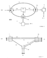
Figure 1 shows a WDM ring network MAN, referred to below
simply as network MAN, having a ring-type optical waveguide
RF, referred to below as ring RF for short, and nodes H, M1
and M2. Shown as nodes are a hub H and, by way of example
for a number of further nodes two add/drop multiplexers M1
and M2. The hub H is connected to a wide-area network WAN.
The add/drop multiplexers M1 and M2 are each connected via
(optical) terminal devices T1 and T2 to local networks LN1
and LN2, respectively. A control device NC transmits via
control channels not shown here a first control signal CS1
to the hub H1, a second control signal CS2 to the first
add/drop multiplexer M1 and a third control signal CS3 to
the second add/drop multiplexer M2.
The add/drop multiplexers M1 and M2 drop one or more
channels from the totality of the channels fed to the input
and forward the remaining channels without modification.
The dropped channels are connected to the inputs of the
terminal devices T1 and T2, respectively; the same number
of channels, in the simplest case of the same wavelength,
is fed back again to the add/drop multiplexer at the output
and added into (added to) the network MAN. While not shown
here, a wavelength conversion may optionally also take
place before adding into the network MAN.
The hub H having in principle identical tasks to those of
the add/drop multiplexers M1 and M2 of dropping and adding
particular channels serves to create a connection to a
wide-area network WAN; from the point of view of task, the
difference between the add/drop multiplexers and a hub is
that the add/drop multiplexers M1 and M2 each as a rule
forward substantially more channels than they separate out
or dropped, whereas the hub drops as a rule most of the
channels arriving at the input for communication with the
wide-area network WAN and correspondingly adds the same
number of channels.
Figure 2 shows the exemplary logical channel relations via
the nodes H, M1 and M2 shown in Figure 1. The bands DH1,
DH2 and AD shown as continuous lines are in this case a
selection of static or predefined bands of channels in the
network MAN. The channels K1 and K2 shown as broken lines
are a selection of dynamically tunable or flexible
channels. The first band DH1 and the first flexible channel
K1 proceed from the wide-area network WAN via the hub and
the first add/drop multiplexer M1 to the first local
network L1. The second band DH2 proceeds from the wide-area
network WAN via the hub and the second add/drop multiplexer
M2 to the second local network LN2. The internal ring band
AD and the second flexible channel K2 proceed from the
first local network LN1 via the first add/drop multiplexer
M1 and the second add/drop multiplexer M2 to the second
local network LN2.
The channels of the predefined bands DH1, DH2 and AD are
statically configured, i.e. their sources and drains are
fixed prior to operating the network MAN. In this
connection, the communication relations, i.e. sources and
drains of the flexible channels K1 and K2, may be tuned
according to communication needs. For this purpose, the
control device NC transmits appropriate control signals
CS1, CS2 and CS3 to the nodes H, M1 and M2, respectively.
Figure 3 shows by way of example a channel and band control
in the first add/drop multiplexer M1 of the network MAN.
The bands DH1, DH2 and AD from Figure 2 shown as continuous
lines and further bands DH3-DHn shown here are predefined
bands of channels. The flexible channels K1 and K2 and
further flexible channels F3 - F1 shown as broken lines are
dynamically reconfigurable channels. The bands DH1 and AD
and the channels K1-Ki are fed to the terminal device T1
and from there back again to the first add/drop multiplexer
M1. The bands DH2-DHm and the channels Kj-Kl are forwarded
unmodified, i.e. said add/drop multiplexer M1 is optically
transparent to these bands or channels in the ideal case,
i.e. in the case of negligible optical attenuation.
Figure 4a shows diagrammatically an exemplary physical
structure of add/drop multiplexers according to the
invention, in this case using the example of the first
multiplexer M1 from the preceding figures. A first
multiplexer input signal IM1 proceeds to a first port 41 of
a first (optical) circulator OZ1. A second port 42 is
connected via an optical filter bank to a first broad-band
filter FAD, a second broad-band filter FDH1 and tunable
(channel) filters F1-F1 connected in series downstream to a
first port of a second (optical) circulator OZ2. From a
third port 43 of the first circulator OZ1, a second
multiplexer output signal OM2 emerges from the first
add/drop multiplexer M1. A second multiplexer input signal
IM2 proceeds to a third port of the second circulator OZ2
and, from a second port 43 of the first circulator OZ1, a
first multiplexer output signal OM1 emerges from the first
add/drop multiplexer M1. The circulators OZ1 and OZ2 are
each configured in such a way that an optical signal
arriving at a first port is dropped again at a second port
in the clockwise direction and an optical signal arriving
at a second optical port is dropped again at a third port
in the clockwise direction.
The input and output signals IH1, OH1, IM1 and OM1
described below are WDM signals having a number of n
wavelengths (signals). The first multiplexer input signal
IM1 arriving at the first port 41 of the first circulator
OZ1 is brought out again at the second port 42 of the first
circulator OZ1. A first part of the channels of said signal
IM1, the channels of the bands AD and DH1 are reflected at
one of the static broad-band filters FAD or FDH1 and
selectable, i.e. reconfigurable channels, are reflected at
one of the tunable filters F1-F1 connected in series to the
second port 42 of the first circulator OZ1 and are brought
out there at the third port 43 as the second multiplexer
output signal OM2. The signal OM2 is then fed, for example,
to a terminal device, not shown here, that, if the signal
OM2 contains a plurality of channels, demultiplexes said
channels of the signals OM2, demodulates them and decodes
and processes the information contained in them. Relevant
new information is then coded and modulated and the
relevant channels multiplexed and fed to the multiplexer M1
as second multiplexer input signal IM2. A second part of
the channels of the first multiplexer input signal IM2
brought out at the second port 42 of the first circulator
OZ1 traverses the said filters FAD, FDH1, F1-F1 without
optical modification except for a possibly small optical
attenuation and is fed to the second circulator OZ2, which
multiplexes said signal with the second multiplexer input
signal IM2 and outputs it as first multiplexer output
signal OM1.
The said filters FAD, FDH1, F1-F1 are implemented, for
example, as Bragg gratings integrated in the optical
waveguide (in-fibre Bragg gratings), referred to below
simply as Bragg filters. Whereas, as is known from the
prior art, the broad-band filters can be implemented by a
certain non-equidistant distribution of the reflection
planes of the said Bragg filters, the tunable Bragg filters
are implemented as narrow-band filters having equidistant
reflection planes whose mutual spacing can be varied within
certain limits by expanding the optical waveguide, for
example, by means of piezoelectric effects. Such techniques
are likewise known from the prior art. The said filters
FAD, FDH1, F1-F1 can also be implemented by means of
further filters known from the prior art. Thus, for
example, the tunable filters F1-F1 can also be implemented
as tunable Fabry-Perot filters or as set of static filters
switched by means of optical switches.
The optical first circulator OZ1 may also be implemented as
a semi-transparent optical mirror that has an analogous
arrangement of ports to that of the first circulator OZ1.
Said mirror is transparent to incident light signals, i.e.
the first multiplexer input signal IM1 is fed from the
first port 41 via the second port 42 to the said filters
FAD, FDH1, F1-F1. The channels reflected from one of these
filters to the port 42 are deflected by the said optical
mirror to port 43 by reflection.
Instead of the second circulator OZ2, which multiplexes, or
adds, the channels not dropped by the first circulator OZ1
with, or to, the channels of the second multiplexer input
signal IM2, an optical coupler may alternatively be used.
As described in the introduction, an (optical) hub H
frequently serves to create a connection to a wide-area
network WAN. A hub H and an add/drop multiplexer can
basically be used for identical tasks; from the point of
view of tasks, the difference between an add/drop
multiplexer and a hub is that an add/drop multiplexer, as a
rule, forwards substantially more channels than it drops,
whereas the hub, as a rule, drops most of che channels for
communication with a wide-area network.
Figure 4b shows diagrammatically an exemplary physical
structure of a hub according to the invention, shown here
on the basis of the example of the hub H from the preceding
figures. A first hub input signal IH1 proceeds to a first
port of a third circulator OZ3. A second port in the
clockwise direction of the third circulator OZ3 is
connected via an optical waveguide to a first broad-band
filter FAD known from Figure 4a and tunable filters F1-F1
are connected in series downstream to the hub port 44. From
a third port in the clockwise direction of the third
circulator OZ3, a first hub output signal OH1 emerges from
the hub H via a wavelength converter C. A second hub output
signal OH2 emerges from the said hub port 44 and a second
hub input signal IH2 proceeds into the said hub port 44.
Those channels of the first hub input signal IH1 that are
reflected by one of the said filters FAD, F1-F1, are fed
back together with the channels of the second hub input
signal IH2 arriving, for example, from a wide area network
WAN not shown here as the first hub output signal OH1 into
the ring RF. The remaining, unreflected channels are fed to
the said wide-area network as second hub output signal OH2.
The channels arriving as second hub input signal IH2 from
said wide-area network are not modified by the said filters
FAD, F1-F1. Since the second hub output signal OH2 and the
second hub input signal IH2 are fed in different directions
in the hub H via an optical waveguide, their channels must
never have identical wavelengths. So that, in the example
described here, the wavelengths of the channels of the
first hub input signal IH1 and of the first hub output
signal OH1 are identical, the wavelengths of the channels
of the second hub input signal IH2 arriving in the hub are
suitably converted. The wavelength converter C can be
partly or completely eliminated if different wavelengths
are provided in each case for both directions of
communication relations between nodes of the network MAN.
The hub described here can in principle undertake the same
tasks as an add/drop multiplexer described in relation to
the preceding Figure 4. However, whereas, in the case of
the add/drop multiplexer M1, filters have to be provided
for those channels that are dropped from the ring RF, in
the case of the hub H, filters have to be provided for
those channels that remain in the network MAN. An add/drop
multiplexer therefore has a number of filters that
increases as the number of channels that have to be dropped
increases, whereas a hub has an increasing number of
filters as the number of channels that remain in the
network RF increases.
The broad-band filters FAD and FDH1 may also be designed as
a cascade of narrow-band filters for each wavelength of the
relevant bands AD and FDH1, respectively.
The hub H and the first add/drop multiplexer M1 in Figure
4a are shown by way of example as nodes of a network MAN
having one H and an indefinite number n of add/drop
multiplexers. In this connection, the internal ring band AD
is, by way of example, a band that remains in the network
MAN and is always dropped at each add/drop multiplexer, fed
to a terminal device, processed therein, fed back and added
again. The first band DH1 is, by way of example, a band
that serves the communication of the first terminal device
T1 via the first add/drop multiplexer M1 and via the hub H
with the wide-area network WAN. Not shown here are further,
for example, n-1 add/drop multiplexers M2-Mn of the network
MAN that always drop, instead of the first band DH1,
another band of the bands DH2-DHn shown in Figure 3 for
communication with the wide-area network WAN. A band
structure of such a network will be explained by reference
to Figure 5 below.
For this purpose, Figure 5 shows an exemplary band
arrangement. Symbolically shown along the λ-axis
(horizontal axis) are z (wavelength) channels λ1-λz. The
first three channels are multiplexed by way of example to
form the first band DH1. The next four channels are
multiplexed by way of example to form the second band DH2.
This is followed by the further bands DH3-DHn mentioned
above, which are not shown here. A number 1 of flexible
channels K1-K1 is then shown. On the far right, two
channels are multiplexed by way of example to form the
internal ring band AD.
Whereas the bands DH1-DHn and AD are, as described above,
permanent bands with fixed communication relations, i.e.
serve dedicated communication relations, the flexible
channels K1-K1 serve flexible communication relations
according to a current communication demand. For this
purpose, the control device NC shown in Figure 1 transmits
appropriate control signals to those nodes that are
affected by a reconfiguration.
If, for example, a first flexible channel K1 that has
hitherto been serving the communication of a first add/drop
multiplexer M1 with the hub H is reconfigured in such a way
that it is then intended to serve the communication of the
second add/drop multiplexer M2 with the hub H, the control
device NC transmits a first control signal CS1 to the first
add/drop multiplexer M1 and a second control signal CS2 to
the second add/drop multiplexer M2. The first add/drop
multiplexer M1 is instructed by the first control signal
CS1 not to drop the first flexible channel K1 any longer.
For this purpose, the appropriate tunable filter F1 is
modified so that it no longer reflects any of the
wavelengths λ1, ..., λz present in the WDM system. In the
case of a piezoelectrically tunable Bragg filter, for
example, this can be achieved by applying a certain voltage
as a controlled variable, as a result of which an optical
wavelength provided with the Bragg filter changes in length
in such a way that, instead of the wavelength of the first
flexible channel K1, a wavelength is reflected that is
situated between the first flexible channel K1 and an
adjacent channel. The second add/drop multiplexer M2 is
instructed by the control signal CS2 to drop the first
flexible channel K1. For this purpose, its tunable filter
F1 is accordingly tuned in such a way that the respective
wavelength is reflected.
In a network described above, the flexible channels K1-K1
can be reconfigured between all the nodes of the network
MAN. However, the appropriate tunable filters F1-F1 have to
be provided for this purpose in every node M1, ..., Mn and
H. This degree of flexibility often is not needed in a
network MAN. A different number of droppable wavelengths
may be provided depending on node. Thus for example, some
nodes may be provided with a smaller number of tunable
filters, each for a subset of the flexible channels present
in the network.
It is possible to organize the channels of a network MAN
according to different classes of service. The classes
shows different degrees of flexibility. Classes of service
without any flexibility are assigned to dedicated node
relations or traffic. Examples for classes with dedicated
node relations are each classes of fixed channels between
add/drop multiplexers and the Hub DH1, DH2, .., DHn, of
fixed channels that are added and dropped at each add/drop
multiplexer or, not mentioned yet, of fixed channels
between add/drop multiplexers. Classes of service with
reduced flexibility are assigned to traffic between each a
sub set of (pre-defined) nodes. Classes of service with
full flexibility are assigned to traffic between all the
nodes of the network MAN, to adapt the resource allocation
to the traffic demand, i.e. this class shoes the channels
K1- K1 described above.
For flexible channels that solely serve communication in
the ring RF, permanently tuned filters may be provided in
the hub H instead of tunable filters F1, ..., F1 or, if such
channels are likewise to be multiplexed to form a band, a
suitable broad-band filter may be provided in the hub H for
said band.
Claims (8)
- Method in a wavelength-division multiplexed (WDM) network (MAN) to organize (wavelength) channels between (optical) nodes (M1, M2, H) of said WDM network, wherein the nodes (M1, M2, H) each have optical filters (FAD, FDH1, F1, ..., F1) for selecting a first set of wavelengths (DH1, AD, K1, ..., Ki) with respect to a set of other wavelengths (DH2, ..., DHn, Kj, ..., Kl) and wherein, in each case, the wavelengths (λ1, ..., λz) of one of these sets are forwarded and the other set of wavelengths is dropped, characterized in that at least one node (M1, M2, H) has both at least one statically preset optical filter (FAD, FDH1) and at least one optical filter (F1, ..., F1) that can be dynamically tuned during operation and in that only respective dynamic optical filters (F1, ..., F1) in the affected nodes (M1, M2, H) have to be tuned in the event of a dynamic reconfiguration of channels.
- Method according to Claim 1, characterized in that the wavelengths of those channels that serve predefined communication relations are at least partly multiplexed to form one or more bands (AD, DH1, ..., DHn) and said bands are selected by means of broad-band optical filters (FAD, FDH1) at affected nodes (M1, M2, H)
- WDM network (MAN) comprising a number of nodes (M1, M2, H) having an optical waveguide (RF) connecting said nodes (M1, M2, H) and reconfiguration means for altering channel relations of the nodes (M1, M2, H) that each have optical filters (FAD, FDH1, F1, ..., F1) for separating a respective first set of wavelengths from a respective second set of wavelengths and means in each case for forwarding the wavelengths of one of said sets and for dropping the wavelengths of the other of said sets, characterized in that the filters (FAD, FHD1, F1, ..., F1) of at least one node have at least one statically preset filter (FAD, FDH1) and at least one dynamic filter (F1, ..., F1) that can be tuned for dynamic reconfiguration.
- WDM network (MAN) according to Claim 3, characterized in that at least some of the optical filters (FAD, FDH1, ..., FDHn, F1, ..., F1) are designed as broad-band filters (FAD, FDH1, ..., FDHn) for filtering bands (AD, DH1, ..., DHn) of two or more adjacent wavelengths.
- WDM network (MAN) according to Claim 3, characterized in that one of the nodes is a so-called hub (H) for accessing a higher-level optical network (WAN) and the other nodes are so-called add/drop multiplexers (M1, M2) for accessing in each case terminal devices or local networks (LN1, LN2), wherein the hub (H) has optical filters (FAD, F1, ..., F1) for selecting a set of wavelengths for forwarding in the WDM network (MAN) and the add/drop multiplexers (M1, M2) have optical filters (FAD, FDH1, F1, ..., F1) each having optical filters for selecting a respective set of wavelengths for dropping from the WDM network (MAN).
- Optical hub (H) for use in a WDM network (MAN) having optical filters for separating a set of wavelengths for forwarding in the WDM network (MAN) characterized in thatat least one of the optical filters (FAD) can be statically preset,at least one of the optical filters (F1, ..., F1) can be dynamically tuned,receiving means for receiving control signals (CS1) are present for the dynamic reconfiguration andcalculating means are present for determining the controlled variables for tuning the dynamically tunable optical filters (F1, ..., F1).
- Optical add/drop multiplexer (M1) for use in a WDM network (MAN) having optical filters (FAD, FDH1, F1, ..., F1) for separating a set of wavelengths for dropping the WDM network (MAN), characterized in thatat least one of the optical filters (FAD, FDH1) can be statically preset,at least one of the optical filters (F1, ..., Fl) can be dynamically tuned,receiving means are present for receiving control signals (CS2) for the dynamic reconfiguration andcalculating means are present for determining the controlled variables for tuning the dynamically tunable optical filters (F1, ..., F1)
- Optical filter bank for use in an optical add/drop multiplexer (M1) or an optical hub (H) having optical filters (FAD, PDH1, F1, ..., F1) for reflecting some of the irradiating wavelengths, characterized in thatat least one of the optical filters (FAD, FDH1) can be statically preset,at least one of the optical filters (F1, ..., F1) can be dynamically tuned andreceiving means for receiving controlled variables are present for tuning the dynamically tunable optical filters (F1, ..., F1).
Priority Applications (2)
| Application Number | Priority Date | Filing Date | Title |
|---|---|---|---|
| EP01440166A EP1267509A1 (en) | 2001-06-12 | 2001-06-12 | Method of organizing wavelength channels in a WDM network and optical hub, optical add/drop multiplexer and optical filter bank therefor |
| US10/150,096 US20020186431A1 (en) | 2001-06-12 | 2002-05-20 | Method of organizing wavelength channels in a wavelength-division multiplexed network as well as an optical wavelength-division multiplexed network, optical hub, optical add/drop multiplexer and optical filter bank therefor |
Applications Claiming Priority (1)
| Application Number | Priority Date | Filing Date | Title |
|---|---|---|---|
| EP01440166A EP1267509A1 (en) | 2001-06-12 | 2001-06-12 | Method of organizing wavelength channels in a WDM network and optical hub, optical add/drop multiplexer and optical filter bank therefor |
Publications (1)
| Publication Number | Publication Date |
|---|---|
| EP1267509A1 true EP1267509A1 (en) | 2002-12-18 |
Family
ID=8183234
Family Applications (1)
| Application Number | Title | Priority Date | Filing Date |
|---|---|---|---|
| EP01440166A Withdrawn EP1267509A1 (en) | 2001-06-12 | 2001-06-12 | Method of organizing wavelength channels in a WDM network and optical hub, optical add/drop multiplexer and optical filter bank therefor |
Country Status (2)
| Country | Link |
|---|---|
| US (1) | US20020186431A1 (en) |
| EP (1) | EP1267509A1 (en) |
Cited By (1)
| Publication number | Priority date | Publication date | Assignee | Title |
|---|---|---|---|---|
| CN1300967C (en) * | 2004-11-26 | 2007-02-14 | 北京理工大学 | Dynamic tunable optical multiplexer composed of tellurium dioxide acoustic-optical tunable filter |
Families Citing this family (3)
| Publication number | Priority date | Publication date | Assignee | Title |
|---|---|---|---|---|
| WO2006035520A1 (en) * | 2004-09-29 | 2006-04-06 | Fujitsu Limited | Light inserting/branching device and optical network system |
| US7634196B2 (en) * | 2004-10-06 | 2009-12-15 | Cisco Technology, Inc. | Optical add/drop multiplexer with reconfigurable add wavelength selective switch |
| GB2549500A (en) * | 2016-04-19 | 2017-10-25 | Airbus Operations Ltd | Node for an optical network |
Citations (3)
| Publication number | Priority date | Publication date | Assignee | Title |
|---|---|---|---|---|
| US6084694A (en) * | 1997-08-27 | 2000-07-04 | Nortel Networks Corporation | WDM optical network with passive pass-through at each node |
| EP1077552A2 (en) * | 1999-08-17 | 2001-02-21 | Siemens Aktiengesellschaft | Arrangement for dropping optical signals |
| WO2001022629A1 (en) * | 1999-09-24 | 2001-03-29 | Telenor As | All-optical network with passive wavelength routers |
Family Cites Families (7)
| Publication number | Priority date | Publication date | Assignee | Title |
|---|---|---|---|---|
| IT1265018B1 (en) * | 1993-08-10 | 1996-10-17 | Cselt Centro Studi Lab Telecom | DEVICE FOR EXTRACTION AND REINSERTION OF AN OPTICAL CARRIER IN OPTICAL COMMUNICATION NETWORKS. |
| US5748349A (en) * | 1996-03-27 | 1998-05-05 | Ciena Corp. | Gratings-based optical add-drop multiplexers for WDM optical communication system |
| US6208443B1 (en) * | 1996-10-03 | 2001-03-27 | International Business Machines Corporation | Dynamic optical add-drop multiplexers and wavelength-routing networks with improved survivability and minimized spectral filtering |
| US5778118A (en) * | 1996-12-03 | 1998-07-07 | Ciena Corporation | Optical add-drop multiplexers for WDM optical communication systems |
| US6069719A (en) * | 1997-07-30 | 2000-05-30 | Ciena Corporation | Dynamically reconfigurable optical add-drop multiplexers for WDM optical communication systems |
| US6614569B2 (en) * | 2001-02-12 | 2003-09-02 | Sycamore Networks, Inc. | System and method for narrow channel spaced dense wavelength division multiplexing/demultiplexing |
| US6959153B2 (en) * | 2001-05-24 | 2005-10-25 | Broadband Royalty Corporation | Dynamically reconfigurable add/drop multiplexer with low coherent cross-talk for optical communication networks |
-
2001
- 2001-06-12 EP EP01440166A patent/EP1267509A1/en not_active Withdrawn
-
2002
- 2002-05-20 US US10/150,096 patent/US20020186431A1/en not_active Abandoned
Patent Citations (3)
| Publication number | Priority date | Publication date | Assignee | Title |
|---|---|---|---|---|
| US6084694A (en) * | 1997-08-27 | 2000-07-04 | Nortel Networks Corporation | WDM optical network with passive pass-through at each node |
| EP1077552A2 (en) * | 1999-08-17 | 2001-02-21 | Siemens Aktiengesellschaft | Arrangement for dropping optical signals |
| WO2001022629A1 (en) * | 1999-09-24 | 2001-03-29 | Telenor As | All-optical network with passive wavelength routers |
Non-Patent Citations (1)
| Title |
|---|
| KAMINOW I P ET AL: "A WIDEBAND ALL0OPTICAL WDM NETWORK", IEEE JOURNAL ON SELECTED AREAS IN COMMUNICATIONS, IEEE INC. NEW YORK, US, vol. 14, no. 5, 1 June 1996 (1996-06-01), pages 780 - 797, XP000590715, ISSN: 0733-8716 * |
Cited By (1)
| Publication number | Priority date | Publication date | Assignee | Title |
|---|---|---|---|---|
| CN1300967C (en) * | 2004-11-26 | 2007-02-14 | 北京理工大学 | Dynamic tunable optical multiplexer composed of tellurium dioxide acoustic-optical tunable filter |
Also Published As
| Publication number | Publication date |
|---|---|
| US20020186431A1 (en) | 2002-12-12 |
Similar Documents
| Publication | Publication Date | Title |
|---|---|---|
| JP4528922B2 (en) | Flexible wavelength band aggregator, deaggregator and hierarchical hybrid optical cross-connect system | |
| US8958695B2 (en) | Optical adding and dropping device and optical transmission apparatus | |
| CA2154017C (en) | Tunable add/drop optical filtering method and apparatus | |
| JP4055797B2 (en) | Optical cross-connect system | |
| CA2130789C (en) | Fast tunable channel dropping filter | |
| US20040252996A1 (en) | Flexible banded MUX/DEMUX architecture for WDM systems | |
| US6323975B1 (en) | Optical add/drop device | |
| CA2130639C (en) | Optical passband filter | |
| EP2946506B1 (en) | Photonic cross-connect with reconfigurable add-drop-functionality | |
| JP4843659B2 (en) | Optical transmission network system, optical transmission device, and passband allocation method using them | |
| US20030128985A1 (en) | Modular optical network node | |
| EP2982066B1 (en) | Optical switch | |
| US6690853B1 (en) | Tunable DWDM demultiplexer | |
| EP1076471B1 (en) | Optical wavelength division multiplexing transmission network device | |
| EP1267509A1 (en) | Method of organizing wavelength channels in a WDM network and optical hub, optical add/drop multiplexer and optical filter bank therefor | |
| EP1009120A2 (en) | Multichannel optical ADD/DROP, multiplexor/demultiplexor | |
| US6782156B2 (en) | Interleaved band demultiplexing/multiplexing system | |
| US6912340B2 (en) | Optical ring interconnect | |
| US6292599B1 (en) | Wavelength selective switching element | |
| Mezhoudi et al. | The value of multiple degree ROADMs on metropolitan network economics | |
| EP2403170B1 (en) | A reconfigurable optical add and drop wavelength multiplexer for an optical network using wavelength division multiplexing | |
| EP1492260A1 (en) | Optical ADD-DROP multiplexer for WDM systems | |
| US20020145784A1 (en) | Optical wavelength switching system with wavelength selective splitters and combiners |
Legal Events
| Date | Code | Title | Description |
|---|---|---|---|
| PUAI | Public reference made under article 153(3) epc to a published international application that has entered the european phase |
Free format text: ORIGINAL CODE: 0009012 |
|
| AK | Designated contracting states |
Kind code of ref document: A1 Designated state(s): AT BE CH CY DE DK ES FI FR GB GR IE IT LI LU MC NL PT SE TR |
|
| AX | Request for extension of the european patent |
Free format text: AL;LT;LV;MK;RO;SI |
|
| 17P | Request for examination filed |
Effective date: 20030120 |
|
| AKX | Designation fees paid |
Designated state(s): AT BE CH CY DE DK ES FI FR GB GR IE IT LI LU MC NL PT SE TR |
|
| STAA | Information on the status of an ep patent application or granted ep patent |
Free format text: STATUS: THE APPLICATION IS DEEMED TO BE WITHDRAWN |
|
| 18D | Application deemed to be withdrawn |
Effective date: 20060117 |