EP1273261A1 - Vessel prosthesis with a sensor - Google Patents
Vessel prosthesis with a sensor Download PDFInfo
- Publication number
- EP1273261A1 EP1273261A1 EP02405437A EP02405437A EP1273261A1 EP 1273261 A1 EP1273261 A1 EP 1273261A1 EP 02405437 A EP02405437 A EP 02405437A EP 02405437 A EP02405437 A EP 02405437A EP 1273261 A1 EP1273261 A1 EP 1273261A1
- Authority
- EP
- European Patent Office
- Prior art keywords
- vascular prosthesis
- measuring probe
- transponder
- vascular
- pressure sensor
- Prior art date
- Legal status (The legal status is an assumption and is not a legal conclusion. Google has not performed a legal analysis and makes no representation as to the accuracy of the status listed.)
- Withdrawn
Links
Images


Classifications
-
- A—HUMAN NECESSITIES
- A61—MEDICAL OR VETERINARY SCIENCE; HYGIENE
- A61B—DIAGNOSIS; SURGERY; IDENTIFICATION
- A61B5/00—Measuring for diagnostic purposes; Identification of persons
- A61B5/68—Arrangements of detecting, measuring or recording means, e.g. sensors, in relation to patient
- A61B5/6846—Arrangements of detecting, measuring or recording means, e.g. sensors, in relation to patient specially adapted to be brought in contact with an internal body part, i.e. invasive
- A61B5/6867—Arrangements of detecting, measuring or recording means, e.g. sensors, in relation to patient specially adapted to be brought in contact with an internal body part, i.e. invasive specially adapted to be attached or implanted in a specific body part
- A61B5/6876—Blood vessel
-
- A—HUMAN NECESSITIES
- A61—MEDICAL OR VETERINARY SCIENCE; HYGIENE
- A61B—DIAGNOSIS; SURGERY; IDENTIFICATION
- A61B5/00—Measuring for diagnostic purposes; Identification of persons
- A61B5/0002—Remote monitoring of patients using telemetry, e.g. transmission of vital signals via a communication network
- A61B5/0031—Implanted circuitry
-
- A—HUMAN NECESSITIES
- A61—MEDICAL OR VETERINARY SCIENCE; HYGIENE
- A61B—DIAGNOSIS; SURGERY; IDENTIFICATION
- A61B5/00—Measuring for diagnostic purposes; Identification of persons
- A61B5/145—Measuring characteristics of blood in vivo, e.g. gas concentration, pH value; Measuring characteristics of body fluids or tissues, e.g. interstitial fluid, cerebral tissue
- A61B5/14546—Measuring characteristics of blood in vivo, e.g. gas concentration, pH value; Measuring characteristics of body fluids or tissues, e.g. interstitial fluid, cerebral tissue for measuring analytes not otherwise provided for, e.g. ions, cytochromes
-
- A—HUMAN NECESSITIES
- A61—MEDICAL OR VETERINARY SCIENCE; HYGIENE
- A61B—DIAGNOSIS; SURGERY; IDENTIFICATION
- A61B5/00—Measuring for diagnostic purposes; Identification of persons
- A61B5/68—Arrangements of detecting, measuring or recording means, e.g. sensors, in relation to patient
- A61B5/6846—Arrangements of detecting, measuring or recording means, e.g. sensors, in relation to patient specially adapted to be brought in contact with an internal body part, i.e. invasive
- A61B5/6879—Means for maintaining contact with the body
- A61B5/6884—Clamps or clips
-
- A—HUMAN NECESSITIES
- A61—MEDICAL OR VETERINARY SCIENCE; HYGIENE
- A61B—DIAGNOSIS; SURGERY; IDENTIFICATION
- A61B5/00—Measuring for diagnostic purposes; Identification of persons
- A61B5/02—Detecting, measuring or recording pulse, heart rate, blood pressure or blood flow; Combined pulse/heart-rate/blood pressure determination; Evaluating a cardiovascular condition not otherwise provided for, e.g. using combinations of techniques provided for in this group with electrocardiography or electroauscultation; Heart catheters for measuring blood pressure
- A61B5/021—Measuring pressure in heart or blood vessels
- A61B5/0215—Measuring pressure in heart or blood vessels by means inserted into the body
-
- A—HUMAN NECESSITIES
- A61—MEDICAL OR VETERINARY SCIENCE; HYGIENE
- A61B—DIAGNOSIS; SURGERY; IDENTIFICATION
- A61B5/00—Measuring for diagnostic purposes; Identification of persons
- A61B5/145—Measuring characteristics of blood in vivo, e.g. gas concentration, pH value; Measuring characteristics of body fluids or tissues, e.g. interstitial fluid, cerebral tissue
-
- A—HUMAN NECESSITIES
- A61—MEDICAL OR VETERINARY SCIENCE; HYGIENE
- A61F—FILTERS IMPLANTABLE INTO BLOOD VESSELS; PROSTHESES; DEVICES PROVIDING PATENCY TO, OR PREVENTING COLLAPSING OF, TUBULAR STRUCTURES OF THE BODY, e.g. STENTS; ORTHOPAEDIC, NURSING OR CONTRACEPTIVE DEVICES; FOMENTATION; TREATMENT OR PROTECTION OF EYES OR EARS; BANDAGES, DRESSINGS OR ABSORBENT PADS; FIRST-AID KITS
- A61F2/00—Filters implantable into blood vessels; Prostheses, i.e. artificial substitutes or replacements for parts of the body; Appliances for connecting them with the body; Devices providing patency to, or preventing collapsing of, tubular structures of the body, e.g. stents
- A61F2/02—Prostheses implantable into the body
- A61F2/04—Hollow or tubular parts of organs, e.g. bladders, tracheae, bronchi or bile ducts
- A61F2/06—Blood vessels
Definitions
- the invention relates to a vascular prosthesis with one on the vascular prosthesis anchored measuring probe with transponder, which measuring probe is suitable, To record measured variables on the basis of which the function of the vascular prosthesis is verifiable, and which transponder to interact with Transmitting / receiving device is formed.
- vascular prostheses In the treatment of vascular injuries, diseases and anomalies vascular prostheses are used in human medicine today.
- the area of application does not only include the intravascular area, but also e.g. also the trachea, digestive tract and urinary tract.
- a typical example of a vascular prosthesis is the Anaconda TM product Sulzer Vascutek Ltd. mentioned in the treatment of Blood vessel enlargement (so-called aneurysms) is used.
- the Vascular prosthesis inserted into the relevant vessel to the expanded Isolate point and relieve pressure, and thus another Prevent stretching and breakage of the affected vessel.
- Fig. 1 shows such a vascular prosthesis when implanted.
- the vascular prosthesis consists essentially of a piece of hose 1, which for insulation the sack-shaped vessel extension 5 was inserted into the blood vessel 3.
- the transitions 4 from the tube piece 1 are open the vessel wall on both sides of the vessel extension 5 is completely sealed, so that no blood can get from the blood vessel 3 into the vessel extension 5.
- the Vessel expansion 5 is thus from the pressure prevailing in vessel 3 relieves and does not expand further. In the event of a leak to the However, transitions 4 get blood into the vasodilation 5, whereupon this continues to expand until it tears. This process is not timely discovered and interrupted, this can be fatal to the patient.
- the proper functioning of the vascular prosthesis i.e.
- the Tightness of the vascular prosthesis 1 and the transitions 4 is for the patient vital.
- a suitable surveillance system which allows the tightness of the implanted vascular prosthesis periodically or to monitor continuously, however, is lacking in the prior art.
- a measuring probe is described in document WO 99/59467, which on End of a catheter is fixed, and with what state parameters and Measured variables, such as temperature, pressure, etc., locally in the Inside the body can be captured.
- WO 99/59467 described measuring probe it is generally not possible without surgical intervention measurements to check the function of implanted To perform vascular prostheses.
- Another disadvantage of the WO 99/59467 described probe is that the probe for the measurement must be introduced separately and positioned at the measuring point, which means additional effort.
- the invention is based on the object, while avoiding the Disadvantages known in the art of a system for Provide functional monitoring of vascular prostheses.
- the system should be suitable for starting leaks early to recognize.
- the vascular prosthesis according to the invention comprises one on the vascular prosthesis anchored measuring probe with transponder, which measuring probe is suitable, To record measured variables on the basis of which the function of the vascular prosthesis is verifiable, and which transponder to interact with Transceiver, e.g. a so-called interrogator.
- Transceiver e.g. a so-called interrogator.
- Measurements on the basis of which the function of the vascular prosthesis is checked can be e.g. mechanical quantities such as volume or Changes in shape, forces, pressures, etc., or biological variables, such as for example pH values, electrolyte, blood gas, or protein concentrations etc.
- the vascular prosthesis according to the invention makes it possible to periodic, e.g. quarterly, collection and Long-term evaluation of the measured variables changes in Relation to the implanted vascular prosthesis, such as an onset of leakage, early detection.
- the measuring probe is preferably mechanical with the vascular prosthesis connected or integrated in the vascular prosthesis.
- the embodiment is the measuring probe by means of fastening lines on the Fixed surface of the vascular implant.
- the vascular prosthesis is preferably flexible and can be used together with the Measuring probe can be implanted via a body vessel.
- This will for example the folded vascular prosthesis and the one on it anchored measuring probe inserted into a catheter and the like prepared catheter inserted into a body vessel and on the for the Implantation intended place placed.
- the vascular prosthesis and the measuring probe anchored to it from the Pushed catheter With the help of a control stick the vascular prosthesis and the measuring probe anchored to it from the Pushed catheter, the vascular prosthesis unfolds to its full length the measuring probe is brought into its end position.
- the method according to the invention has the advantage that a separate There is no need to implant the measuring probe.
- the measuring probe can also be used with the Process according to the invention placed in a simple manner at points are only operative after inserting the vascular prosthesis are accessible, e.g. the outer surface of the vascular prosthesis.
- the vascular prosthesis is preferably essentially tubular trained and / or the shape of a vessel or vessel part replicated to be pathological in the implanted state Isolate vasodilation from the inside, with the measuring probe on the outer surface of the vascular prosthesis is provided so that the Tightness of the vascular prosthesis compared to the enlarged vessel can be monitored.
- the measuring probe comprises an envelope and a pressure sensor which is arranged inside the shell, the Cover is filled with a pressure-transmitting medium.
- the Sleeve elastic, so that the entire surface of the Cover is effective as a pressure sensor. This will be the one for pressure measurement minimizes the necessary deformation, which is particularly advantageous if Deposits have formed on the measuring probe.
- the transponder is preferably designed as a passive transponder.
- On passive transponder is an electronic transmission device for wireless transmission of measured values without own power supply.
- the pressure sensor is preferably in the passive transponder circuit integrated, for example by adding a capacitive transponder Includes pressure sensor and an inductor, wherein the capacitive pressure sensor and the inductance are connected to one another Form a resonant circuit.
- the passive transponder can optionally also have one inductive pressure sensor and a capacitance, which together form a Form a resonant circuit. Such a transponder can with minimal Effort can be realized.
- the passive transponder preferably comprises additionally a non-linear component, for example a capacitance diode.
- Harmonics are generated by the nonlinear component, so that a Measured value to be transmitted is transmitted at a frequency which is from the frequency of the interrogator radiation with which the transponder is excited is different. As a result, the recipient can Transponder signal can be better separated from the interrogator radiation.
- a transmitting / receiving device that is specifically designed to interact with the transponder of the vascular prosthesis according to the invention is suitable Subject of claim 12.
- the transmitting / receiving device comprises an interrogator antenna designed to enclose the body part in which the vascular prosthesis is implanted, e.g. in the belly.
- The has the body part completely enclosed by the interrogator antenna the advantage that a better coupling between the interrogator antenna and Transponder is reached when the vascular prosthesis and the associated one Transponders are located deep inside the body.
- the Interrogator antenna arranged in a belt-like device.
- the interrogator antenna preferably comprises at least one primary and a secondary antenna, the two antennas being coupled in such a way that the far field of the coupled antennas is weakened.
- This Antenna arrangement has the advantage that interference with surrounding devices and radio services avoided due to the relatively strong interrogator radiation can be without the wireless power supply of the transponder is affected.
- FIG. 1 A vascular prosthesis according to a first embodiment of the present invention is shown in FIG.
- the vascular prosthesis includes a piece of hose 1, which is used to isolate the bag-shaped Vessel extension 5 was inserted into the blood vessel 3, and one on Hose section 1 anchored measuring probe 2. If the vascular prosthesis is intact the transitions 4 from the tube piece 1 to the vessel wall on both sides of the Vessel enlargement 5 is completely tight, so that no blood from the blood vessel 3 in the vessel extension 5 can reach. The vessel extension 5 is thus relieved of the pressure prevailing in the vessel 3 and does not expand further out.
- the measuring probe 2 is on the outer surface of the Hose section 1 anchored to ensure the tightness of the hose section 1 to monitor against the vessel extension 5.
- the measuring probe 2 comprises an elastic sleeve 25, a pressure sensor 6 for measuring the pressure in the enclosed Volume between the hose section 1 and the vessel extension 5 and a passive transponder 40 with an antenna 10 for transmitting the measured pressure values.
- the pressure sensor 6 is inside the casing 25 arranged, and the sleeve 25 with a pressure-transmitting medium 26, For example, an oil or gel filled, which the on the envelope 25th acting pressure on the pressure sensor 6 transmits. This arrangement is Particularly advantageous if deposits form on the measuring probe have, because the deformation of the envelope necessary for the pressure measurement are minimal.
- the pressure sensor 6 can also be arranged externally and with a cable to the transponder 40 or in the Measuring probe cover 25 can be integrated.
- the measuring principle of the pressure sensor can be piezoresistive, capacitive, inductive, magneto-elastic, etc. type.
- the pressure sensor is in the exemplary embodiment with a passive transponder connected.
- a passive transponder is an electronic one Transmission device for wireless transmission of measured values without own power supply.
- the transponder is activated by a transmitting / receiving device, hereinafter also called an interrogator, illuminated with high-frequency radiation, whereupon the transponder in turn emits a high-frequency carrier signal, which with the transmitting information is modulated.
- This transponder signal can Receivers of the transceiver received and for the purpose Obtaining the transmitted information can be demodulated.
- the measuring circuit is expediently supplied with energy also from the radiation energy absorbed by the transponder.
- FIG. 4 shows a block diagram of a passive transponder 40 according to the first embodiment of the present invention.
- the transponder 40 is caused by the high frequency emitted by an interrogator Radiation field supplied with energy.
- the radiation induces in an antenna 10 a high-frequency voltage, which in a rectifier 11 rectified and fed to a feed module 12.
- a feed module 12 In the feed module 12 there is a storage capacitor which matches that of the rectifier supplied DC is charged, as well as switches that switch the transponder Turn on 40 when the voltage on the capacitor is the necessary Has reached operating voltage and switch off the transponder 40 again, if the minimum operating voltage is undershot.
- This type of Energy supply is a sequential mode of operation.
- the sequential mode of operation has the advantage of being a much weaker one Radiation field is required than in duplex operation, where interrogator and Transponders are active at the same time because the transmission phase is usually takes only fractions of a second, while for the charging phase in sequential operation is available for several seconds.
- the from Pressure sensor 6 supplied measured value is in a signal processing module 7 processed where it is, for example, in a frequency-modulated subcarrier can be implemented or digitized.
- the signal processed in this way is fed into a modulator 8, where it is generated in an oscillator 9 Carrier modulated. This modulated carrier is inserted into the antenna 10 fed in and emitted from there as a transponder signal.
- the Carrier signal can instead of with the oscillator 9 by reflection (Reflection) or frequency multiplication or division from the Interrogator radiation can be obtained.
- Modulators can also modulate the antenna impedance of the Transponders can be applied. Will the carrier signal through Retroreflection obtained from the interrogator radiation, this results in the so-called load, absorption or backscatter modulation.
- the Pressure sensor integrated in the passive transponder circuit by the Transponder 40 ', a capacitive pressure sensor 6' and an inductor 28 includes.
- the capacitive pressure sensor 6 'and the inductance 28 are so interconnected so that they form a resonant circuit.
- the resonant circuit simultaneously emits high-frequency radiation, whereby the phase of the emitted radiation changes depending on the pressure.
- the transponder 40 as shown in FIG.
- the passive transponders 40 ', 40 can be realized with minimal effort.
- the passive transponders 40 ', 40 “additionally a non-linear component 29, for example a capacitance diode. Through the non-linear component 29 harmonics are generated so that a measured value to be transmitted with a Frequency is transmitted, which depends on the frequency of the interrogator radiation, with which the transponder 40 ', 40 "is excited, is different can receive the transponder signal better from the Interrogator radiation can be separated.
- the interrogator antenna 13 is electrical shielded loop antenna built. Thanks to Loop building it is possible to the part of the body in which the Vascular prosthesis is used to enclose what the antenna The advantage is that a better coupling between the interrogator antenna and Transponder is reached when the vascular prosthesis and the associated one Transponders are located deep inside the body.
- the loop antenna 13 is like constructed as follows: The actual antenna wire 14 is located coaxially in the Inside a tubular shield 15, which at a point 16 is interrupted. The interrupted shielding causes the Near field of the antenna only the magnetic and not the disturbing electrical Field occurs.
- a Capacitor with which the antenna can be tuned to resonance.
- the feed point 17 is connected to a shielded cable 18 High frequency generator 19 connected.
- the one emitted by the transponder Transponder signal is received by the same antenna 13, on Feed point 17 removed and a crossover 20 and a Cable 21 passed to a receiver 22.
- the crossover 20 prevents that the relatively strong interrogator signal reaches the receiver input and damaged it.
- 6b shows a preferred embodiment of an interrogator antenna according to the present invention.
- the compensation loops 23 are fed by compensation currents, their total amplitude correspond approximately to the antenna current in the loop antenna 13, and their Phase is shifted by 180 ° with respect to the antenna current. This will the far field of the loop antenna 13 largely suppressed without that Near field important for wireless energy supply significantly weakened becomes.
- the compensation currents can, for example, from the entry point 17 of the antenna 13 and removed via an adaptation circuit 24 are fed to the compensation loops 23.
- Adjustment circuit 24 can adjust the amplitude and phase of the Compensation currents set for optimal suppression of the far field become.
- This variant has the advantage that malfunctions of other devices and radio services through the far field of the relatively strong Interrogator radiation, which is used for the energy supply of the passive Transponders needed to be largely avoided.
- the compensation system comprises only one embodiment variant Compensation loop 23. In a further embodiment variant, the Compensation loops 23 not fed.
- the interrogator antenna which is either antenna 13 alone, or the antenna 13 and that in the above embodiment Compensation system 17, 23 and 24 described, as more flexible Belt built up.
- the strap can be used for measurement around the appropriate Body part are placed in which the vascular prosthesis with the associated Measuring probe was used.
- An interrogator antenna in the shape of a Belt is shown in Fig. 6c.
- FIG. 8a shows a vascular prosthesis according to a second Embodiment of the present invention during the introductory phase and Fig. 8b the same vascular prosthesis in a fully deployed state.
- the tightly folded vascular prosthesis 31 is inserted into a catheter 34.
- a measuring probe 32 which is attached at both ends to the outer surface of the vascular prosthesis 31 with the aid of two fastening lines 33 each.
- the measuring probe 32 has a slim volume and is equipped with a biocompatible surface. The lengths of the measuring probe 32 and the rear fastening lines 33 are approximately the same.
- a control rod 35 runs along the catheter 34 and is used to eject and unfold the vascular prosthesis 31.
- FIG. 9a, b and c show the insertion of the vascular prosthesis according to the second embodiment of the present invention in a Vasodilation, a so-called aneurysm.
- the tightly folded Vascular prosthesis 31 together with the measuring probe 32, which by means of the Fastening lines 33 is attached to the vascular prosthesis 31 in one Catheter 34 used.
- 9a shows the vascular prosthesis 31 folded up in the catheter 34.
- the catheter 34 prepared in this way is in a body vessel is inserted and attached to the one intended for implantation Place, for example an aneurysm 36.
- Measuring probe 32 is pushed out of catheter 34 and vascular prosthesis 31 unfolded.
- 9b shows the vascular prosthesis 31 during the unfolding.
- the measuring probe 32 is passed through the fastening lines on the outer surface of the vascular prosthesis 31 drawn.
- the vascular prosthesis unfolded to full length and the four fastening lines 33 are stretched so that the probe 32 on the outer surface of the Vascular prosthesis 31 is fixed.
- 9c shows the vascular prosthesis 31 completely unfolds in the aneurysm 36.
- the method according to the invention has the The advantage that a separate implantation of the measuring probe is not necessary. Can continue the measuring probe with the inventive method in a simple manner be placed in places only after the vascular prosthesis has been inserted are still operationally accessible, e.g. the outer surface of the Vascular prosthesis.
Abstract
Description
Die Erfindung betrifft eine Gefässprothese mit einer an der Gefässprothese verankerbaren Messsonde mit Transponder, welche Messsonde geeignet ist, Messgrössen zu erfassen, an Hand derer die Funktion der Gefässprothese überprüfbar ist, und welcher Transponder zum Wechselwirken mit einer Sende-/Empfangsvorrichtung ausgebildet ist.The invention relates to a vascular prosthesis with one on the vascular prosthesis anchored measuring probe with transponder, which measuring probe is suitable, To record measured variables on the basis of which the function of the vascular prosthesis is verifiable, and which transponder to interact with Transmitting / receiving device is formed.
Bei der Behandlung von Gefässverletzungen, -erkrankungen und -anomalien
kommen heute in der Humanmedizin Gefässprothesen zum Einsatz. Der
Einsatzbereich umfasst dabei nicht nur den intravaskulären Bereich, sondern
z.B. auch die Luftröhre, den Verdauungstrakt und die Harnwege. Als
typisches Beispiel einer Gefässprothese sei hier das Produkt Anaconda™ der
Firma Sulzer Vascutek Ltd. erwähnt, welches bei der Behandlung von
Blutgefässerweiterungen (sog. Aneurysmen) eingesetzt wird. Dabei wird die
Gefässprothese in das betreffende Gefäss eingeschoben, um die geweitete
Stelle zu isolieren und vom Druck zu entlasten, und damit eine weitere
Dehnung und den Bruch des betroffenen Gefässes zu verhindern. Fig. 1 zeigt
eine solche Gefässprothese im implantierten Zustand. Die Gefässprothese
besteht im Wesentlichen aus einem Schlauchstück 1, welches zur Isolation
der sackförmigen Gefässerweiterung 5 in das Blutgefäss 3 eingesetzt wurde.
Bei intakter Gefässprothese sind die Übergänge 4 vom Schlauchstück 1 auf
die Gefässwand beidseits der Gefässerweiterung 5 vollkommen dicht, so dass
kein Blut vom Blutgefäss 3 in die Gefässerweiterung 5 gelangen kann. Die
Gefässerweiterung 5 ist somit von dem im Gefäss 3 herrschenden Druck
entlastet und dehnt sich nicht weiter aus. Im Fall einer Leckage an den
Übergängen 4 gelangt jedoch Blut in die Gefässerweiterung 5, worauf sich
diese weiter ausdehnt bis sie reisst. Wird dieser Vorgang nicht rechtzeitig
entdeckt und unterbrochen, so kann dies für den Patienten tödlich sein. Die
ordnungsgemässe Funktion der Gefässprothese, d.h. in diesem Fall die
Dichtigkeit der Gefässprothese 1 und der Übergänge 4, ist für den Patienten
von entscheidender Bedeutung. Ein geeignetes Überwachungssystem,
welches erlaubt, die Dichtigkeit, der implantierten Gefässprothese periodisch
oder kontinuierlich zu überwachen, fehlt jedoch im Stand der Technik. Zwar
wird im Dokument WO 99/59467 eine Messsonde beschrieben, welche am
Ende eines Katheters fixiert ist, und mit welcher Zustandsparameter und
Messgrössen, wie beispielsweise Temperatur, Druck usw., lokal im
Körperinnern erfasst werden können. Mit der im Dokument WO 99/59467
beschriebenen Messsonde ist es jedoch im Allgemeinen nicht möglich, ohne
chirurgischen Eingriff Messungen zur Funktionsüberprüfung von implantierten
Gefässprothesen vorzunehmen. Ein weiterer Nachteil der im Dokument WO
99/59467 beschriebenen Messsonde besteht darin, dass die Messsonde für
die Messung extra eingeführt und an der Messstelle positioniert werden muss,
was einen zusätzlichen Aufwand bedeutet.In the treatment of vascular injuries, diseases and anomalies
vascular prostheses are used in human medicine today. The
The area of application does not only include the intravascular area, but also
e.g. also the trachea, digestive tract and urinary tract. As
A typical example of a vascular prosthesis is the Anaconda ™ product
Sulzer Vascutek Ltd. mentioned in the treatment of
Blood vessel enlargement (so-called aneurysms) is used. The
Vascular prosthesis inserted into the relevant vessel to the expanded
Isolate point and relieve pressure, and thus another
Prevent stretching and breakage of the affected vessel. Fig. 1 shows
such a vascular prosthesis when implanted. The vascular prosthesis
consists essentially of a piece of
Der Erfindung liegt die Aufgabe zu Grunde, unter Vermeidung der aus dem Stand der Technik bekannten Nachteile ein System zur Funktionsüberwachung von Gefässprothesen zur Verfügung zu stellen. Insbesondere soll das System geeignet sein, beginnende Leckagen frühzeitig zu erkennen.The invention is based on the object, while avoiding the Disadvantages known in the art of a system for Provide functional monitoring of vascular prostheses. In particular, the system should be suitable for starting leaks early to recognize.
Diese Aufgabe wird durch die in den unabhängigen Ansprüchen definierten Gegenstände der Erfindung gelöst.This task is defined by those in the independent claims Objects of the invention solved.
Die erfindungsgemässe Gefässprothese umfasst eine an der Gefässprothese verankerbare Messsonde mit Transponder, welche Messsonde geeignet ist, Messgrössen zu erfassen, an Hand derer die Funktion der Gefässprothese überprüfbar ist, und welcher Transponder zum Wechselwirken mit einer Sende-/Empfangsvorrichtung, z.B. einem sog. Interrogator, ausgebildet ist. The vascular prosthesis according to the invention comprises one on the vascular prosthesis anchored measuring probe with transponder, which measuring probe is suitable, To record measured variables on the basis of which the function of the vascular prosthesis is verifiable, and which transponder to interact with Transceiver, e.g. a so-called interrogator.
Messgrössen, an Hand derer die Funktion der Gefässprothese überprüft werden kann, sind z.B. mechanische Grössen, wie beispielsweise Volumenoder Formänderungen, Kräfte, Drücke u.ä., oder biologische Grössen, wie beispielsweise pH-Werte, Elektrolyt-, Blutgas-, oder Proteinkonzentrationen u.ä.. Die erfindungsgemässe Gefässprothese ermöglicht es, durch periodische, beispielsweise vierteljährliche, Erfassung und Langzeitauswertung der besagten Messgrössen Veränderungen im Zusammenhang mit der implantierten Gefässprothese, wie beispielsweise eine beginnende Leckage, frühzeitig zu erkennen.Measurements on the basis of which the function of the vascular prosthesis is checked can be e.g. mechanical quantities such as volume or Changes in shape, forces, pressures, etc., or biological variables, such as for example pH values, electrolyte, blood gas, or protein concentrations etc. The vascular prosthesis according to the invention makes it possible to periodic, e.g. quarterly, collection and Long-term evaluation of the measured variables changes in Relation to the implanted vascular prosthesis, such as an onset of leakage, early detection.
Vorzugsweise ist die Messsonde mechanisch mit der Gefässprothese verbunden oder in der Gefässprothese integriert. In einer bevorzugten Ausführungsform ist die Messsonde mittels Befestigungsleinen auf der Oberfläche des Gefässimplantates befestigt.The measuring probe is preferably mechanical with the vascular prosthesis connected or integrated in the vascular prosthesis. In a preferred one The embodiment is the measuring probe by means of fastening lines on the Fixed surface of the vascular implant.
Vorzugsweise ist die Gefässprothese flexibel und kann zusammen mit der Messsonde via ein Körpergefäss implantiert werden. Dazu wird beispielsweise die zusammengefaltete Gefässprothese und die an derselben verankerte Messsonde in einen Katheter eingesetzt und der derart vorbereitete Katheter in ein Körpergefäss eingeführt und an der für die Implantation vorgesehenen Stelle platziert. Mit Hilfe eines Steuerstabes wird die Gefässprothese und die an derselben verankerte Messsonde aus dem Katheter geschoben, wobei die Gefässprothese bis zur vollen Länge entfaltet wird, und die Messsonde in Ihre Endlage gebracht wird. Das erfindungsgemässe Verfahren hat den Vorteil, dass eine separate Implantation der Messsonde entfällt. Weiter kann die Messsonde mit dem erfindungsgemässen Verfahren in einfacher Weise an Stellen platziert werden, die nach dem Einsetzen der Gefässprothese nur noch operativ zugänglich sind, wie z.B. die äussere Oberfläche der Gefässprothese.The vascular prosthesis is preferably flexible and can be used together with the Measuring probe can be implanted via a body vessel. This will for example the folded vascular prosthesis and the one on it anchored measuring probe inserted into a catheter and the like prepared catheter inserted into a body vessel and on the for the Implantation intended place placed. With the help of a control stick the vascular prosthesis and the measuring probe anchored to it from the Pushed catheter, the vascular prosthesis unfolds to its full length the measuring probe is brought into its end position. The The method according to the invention has the advantage that a separate There is no need to implant the measuring probe. The measuring probe can also be used with the Process according to the invention placed in a simple manner at points are only operative after inserting the vascular prosthesis are accessible, e.g. the outer surface of the vascular prosthesis.
Vorzugsweise ist die Gefässprothese im Wesentlichen schlauchartig ausgebildet und/oder der Form eines Gefässes oder Gefässteiles nachgebildet, um im implantierten Zustand eine krankhafte Gefässerweiterung von innen zu isolieren, wobei die Messsonde auf der äusseren Oberfläche der Gefässprothese vorgesehen ist, so dass die Dichtigkeit der Gefässprothese gegenüber dem erweiterten Gefäss überwachbar ist.The vascular prosthesis is preferably essentially tubular trained and / or the shape of a vessel or vessel part replicated to be pathological in the implanted state Isolate vasodilation from the inside, with the measuring probe on the outer surface of the vascular prosthesis is provided so that the Tightness of the vascular prosthesis compared to the enlarged vessel can be monitored.
In einer bevorzugten Ausführungsform umfasst die Messsonde eine Hülle und einen Drucksensor, welcher im Inneren der Hülle angeordnet ist, wobei die Hülle mit einem druckübertragenden Medium gefüllt ist. Vorzugsweise ist die Hülle elastisch, so dass bei der Druckmessung die gesamte Oberfläche der Hülle als Druckaufnehmer wirksam ist. Damit wird die für die Druckmessung notwendige Deformation minimiert, was besonders vorteilhaft ist, wenn sich Ablagerungen auf der Messsonde gebildet haben.In a preferred embodiment, the measuring probe comprises an envelope and a pressure sensor which is arranged inside the shell, the Cover is filled with a pressure-transmitting medium. Preferably the Sleeve elastic, so that the entire surface of the Cover is effective as a pressure sensor. This will be the one for pressure measurement minimizes the necessary deformation, which is particularly advantageous if Deposits have formed on the measuring probe.
Vorzugsweise ist der Transponder als passiver Transponder ausgebildet. Ein passiver Transponder ist eine elektronische Übermittlungsvorrichtung zur drahtlosen Übermittlung von Messwerten ohne eigene Stromversorgung.The transponder is preferably designed as a passive transponder. On passive transponder is an electronic transmission device for wireless transmission of measured values without own power supply.
Vorzugsweise wird der Drucksensor in die passive Transponderschaltung integriert, beispielsweise indem der Transponder einen kapazitiven Drucksensor und eine Induktivität umfasst, wobei der kapazitive Drucksensor und die Induktivität so miteinander verbunden sind, dass sie einen Schwingkreis bilden. Wahlweise kann der passive Transponder auch einen induktiven Drucksensor und eine Kapazität umfassen, die zusammen einen Schwingkreis bilden. Ein derartiger Transponder kann mit minimalem Aufwand realisiert werden. Vorzugsweise umfasst der passive Transponder zusätzlich ein nichtlineares Bauelement, beispielsweise eine Kapazitätsdiode. Durch das nichtlineare Bauelement werden Oberwellen erzeugt, so dass ein zu übermittelnder Messwert mit einer Frequenz übermittelt wird, welche von der Frequenz der Interrogatorstrahlung, mit welcher der Transponder angeregt wird, verschieden ist. Dadurch kann empfängerseits das Transpondersignal besser von der Interrogatorstrahlung getrennt werden.The pressure sensor is preferably in the passive transponder circuit integrated, for example by adding a capacitive transponder Includes pressure sensor and an inductor, wherein the capacitive pressure sensor and the inductance are connected to one another Form a resonant circuit. The passive transponder can optionally also have one inductive pressure sensor and a capacitance, which together form a Form a resonant circuit. Such a transponder can with minimal Effort can be realized. The passive transponder preferably comprises additionally a non-linear component, for example a capacitance diode. Harmonics are generated by the nonlinear component, so that a Measured value to be transmitted is transmitted at a frequency which is from the frequency of the interrogator radiation with which the transponder is excited is different. As a result, the recipient can Transponder signal can be better separated from the interrogator radiation.
Eine Sende-/Empfangsvorrichtung, welche speziell für das Wechselwirken mit
dem Transponder der erfindungsgemässen Gefässprothese geeignet ist, ist
Gegenstand des Anspruchs 12. Die Sende-/Empfangsvorrichtung umfasst
eine Interrogatorantenne, die zum Umschliessen des Körperteiles ausgelegt
ist, in welchem die Gefässprothese implantiert ist, wie z.B. im Bauch. Das
vollständige Umschliessen des Körperteiles durch die Interrogatorantenne hat
den Vorteil, dass eine bessere Kopplung zwischen Interrogatorantenne und
Transponder erreicht wird, wenn sich die Gefässprothese und der zugehörige
Transponder tief im Körperinnern befinden. Vorzugsweise ist die
Interrogatorantenne in einer gurtähnlichen Vorrichtung angeordnet.
Vorzugsweise umfasst die Interrogatorantenne mindestens eine Primär- und
eine Sekundärantenne, wobei die beiden Antennen derart gekoppelt sind,
dass das Fernfeld der gekoppelten Antennen abgeschwächt wird. Diese
Antennenanordnung hat den Vorteil, dass eine Störung umliegender Geräte
und Funkdienste durch die relativ starke Interrogatorstrahlung vermieden
werden kann, ohne dass die drahtlose Energieversorgung des Transponders
beeinträchtigt wird.A transmitting / receiving device that is specifically designed to interact with
the transponder of the vascular prosthesis according to the invention is suitable
Subject of
Weitere vorteilhafte Ausführungsformen gehen aus den abhängigen Ansprüchen und der Zeichnung hervor.Further advantageous embodiments can be found in the dependent ones Claims and the drawing.
Im Folgenden wird die Erfindung an Hand der Ausführungsbeispiele und an Hand der Zeichnung näher erläutert. Es zeigen:
- Fig.1:
- einen Längsschnitt durch eine herkömmliche Gefässprothese im implantierten Zustand,
- Fig. 2:
- einen Längsschnitt durch eine Gefässprothese gemäss einem ersten Ausführungsbeispiel der vorliegenden Erfindung im implantierten Zustand,
- Fig. 3
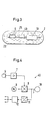
- einen Schnitt durch eine Messsonde gemäss dem ersten Ausführungsbeispiel der vorliegenden Erfindung,
- Fig. 4
- ein Blockschaltbild eines passiven Transponders gemäss dem ersten Ausführungsbeispiel der vorliegenden Erfindung,
- Fig. 5a
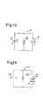
- einen Schaltplan einer Ausführungsvariante eines passiven Transponders mit integriertem kapazitivem Drucksensor,
- Fig. 5b
- einen Schaltplan einer Ausführungsvariante eines passiven Transponders mit integriertem induktivem Drucksensor,
- Fig. 6a
- eine Interrogatorantenne gemäss dem ersten Ausführungsbeispiel der vorliegenden Erfindung,
- Fig. 6b
- eine Interrogatorantenne mit einer Primär- und zwei Sekundärantennen,
- Fig. 6c
- den konstruktiven Aufbau der Interrogatorantenne von Fig. 6b,
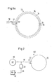
- Fig. 7
- ein Blockschaltbild eines Interrogators gemäss dem ersten Ausführungsbeispiel der vorliegenden Erfindung,
- Fig. 8a
- eine Gefässprothese gemäss einem zweiten Ausführungsbeispiel der vorliegenden Erfindung während der Einführungsphase,
- Fig. 8b
- die Gefässprothese gemäss dem zweiten Ausführungsbeispiel in vollständig entfaltetem Zustand,
- Fig. 9a
- einen Längsschnitt durch die Gefässprothese gemäss dem zweiten Ausführungsbeispiel zusammengefaltet in einem Katheter,
- Fig. 9b
- einen Längsschnitt durch die Gefässprothese gemäss dem zweiten Ausführungsbeispiel während der Entfaltung,
- Fig. 9c
- einen Längsschnitt durch die Gefässprothese gemäss dem zweiten Ausführungsbeispiel vollständig entfaltet in einem Aneurysma.
- Fig.1:
- a longitudinal section through a conventional vascular prosthesis in the implanted state,
- Fig. 2:
- 2 shows a longitudinal section through a vascular prosthesis according to a first exemplary embodiment of the present invention in the implanted state,
- Fig. 3
- 3 shows a section through a measuring probe according to the first exemplary embodiment of the present invention,
- Fig. 4
- 2 shows a block diagram of a passive transponder according to the first exemplary embodiment of the present invention,
- Fig. 5a
- 1 shows a circuit diagram of an embodiment variant of a passive transponder with an integrated capacitive pressure sensor,
- Fig. 5b
- 1 shows a circuit diagram of an embodiment variant of a passive transponder with an integrated inductive pressure sensor,
- Fig. 6a
- an interrogator antenna according to the first embodiment of the present invention,
- Fig. 6b
- an interrogator antenna with one primary and two secondary antennas,
- Fig. 6c
- the structural design of the interrogator antenna of Fig. 6b,
- Fig. 7
- 2 shows a block diagram of an interrogator according to the first exemplary embodiment of the present invention,
- Fig. 8a
- a vascular prosthesis according to a second embodiment of the present invention during the introductory phase,
- Fig. 8b
- the vascular prosthesis according to the second embodiment in the fully deployed state,
- Fig. 9a
- 2 shows a longitudinal section through the vascular prosthesis according to the second exemplary embodiment, folded in a catheter,
- Fig. 9b
- 2 shows a longitudinal section through the vascular prosthesis according to the second exemplary embodiment during deployment,
- Fig. 9c
- a longitudinal section through the vascular prosthesis according to the second embodiment fully unfolded in an aneurysm.
Eine Gefässprothese gemäss einem ersten Ausführungsbeispiel der
vorliegenden Erfindung ist in Fig. 2 dargestellt. Die Gefässprothese umfasst
einem Schlauchstück 1, welches zur Isolation der sackförmigen
Gefässerweiterung 5 in das Blutgefäss 3 eingesetzt wurde, und eine am
Schlauchstück 1 verankerte Messsonde 2. Bei intakter Gefässprothese sind
die Übergänge 4 vom Schlauchstück 1 auf die Gefässwand beidseits der
Gefässerweiterung 5 vollkommen dicht, so dass kein Blut vom Blutgefäss 3 in
die Gefässerweiterung 5 gelangen kann. Die Gefässerweiterung 5 ist somit
von dem im Gefäss 3 herrschenden Druck entlastet und dehnt sich nicht
weiter aus. Die Messsonde 2 ist auf der äusseren Oberfläche des
Schlauchstücks 1 verankert, um die Dichtigkeit des Schlauchstücks 1
gegenüber der Gefässerweiterung 5 zu überwachen.A vascular prosthesis according to a first embodiment of the
present invention is shown in FIG. The vascular prosthesis includes
a piece of
Fig. 3 zeigt eine Messsonde 2 gemäss dem ersten Ausführungsbeispiel der
vorliegenden Erfindung. Die Messsonde 2 umfasst eine elastische Hülle 25,
einen Drucksensor 6 zur Messung des Druckes im eingeschlossenen
Volumen zwischen dem Schlauchstück 1 und der Gefässerweiterung 5 und
einen passiven Transponder 40 mit einer Antenne 10 zur Übermittlung der
gemessenen Druckwerte. Der Drucksensor 6 ist im Innern der Hülle 25
angeordnet, und die Hülle 25 mit einem druckübertragenden Medium 26,
beispielsweise einem Öl oder Gel, gefüllt, welches den auf die Hülle 25
wirkenden Druck auf den Drucksensor 6 überträgt. Diese Anordnung ist
besonders vorteilhaft, wenn sich Ablagerungen auf der Messsonde gebildet
haben, da die für die Druckmessung notwendigen Deformationen der Hülle
minimal sind. Der Drucksensor 6 kann jedoch auch extern angeordnet und mit
einem Kabel mit dem Transponder 40 verbunden werden oder in die
Messsondenhülle 25 integriert sein. Das Messprinzip des Drucksensors kann
piezoresistiver, kapazitiver, induktiver, magnetoelastischer, etc. Art sein.3 shows a measuring
Der Drucksensor ist im Ausführungsbeispiel mit einem passiven Transponder verbunden. Ein passiver Transponder ist eine elektronische Übermittlungsvorrichtung zur drahtlosen Übermittlung von Messwerten ohne eigene Stromversorgung. Zu seiner Aktivierung wird der Transponder von einer Sende-/Empfangsvorrichtung, im Folgenden auch Interrogator genannt, mit hochfrequenter Strahlung angestrahlt, worauf der Transponder seinerseits ein hochfrequentes Trägersignal aussendet, welches mit der zu übertragenden Information moduliert ist. Dieses Transpondersignal kann im Empfänger der Sende-/Empfangsvorrichtung empfangen und zwecks Gewinnung der übertragenen Information demoduliert werden. Zweckmässigerweise erfolgt die Energieversorgung der Messschaltung ebenfalls aus der vom Transponder aufgenommenen Strahlungsenergie.The pressure sensor is in the exemplary embodiment with a passive transponder connected. A passive transponder is an electronic one Transmission device for wireless transmission of measured values without own power supply. The transponder is activated by a transmitting / receiving device, hereinafter also called an interrogator, illuminated with high-frequency radiation, whereupon the transponder in turn emits a high-frequency carrier signal, which with the transmitting information is modulated. This transponder signal can Receivers of the transceiver received and for the purpose Obtaining the transmitted information can be demodulated. The measuring circuit is expediently supplied with energy also from the radiation energy absorbed by the transponder.
Fig. 4 zeigt ein Blockschaltbild eines passiven Transponders 40 gemäss dem
ersten Ausführungsbeispiel der vorliegenden Erfindung. Der Transponder 40
wird durch das von einem Interrogator ausgestrahlte hochfrequente
Strahlungsfeld mit Energie versorgt. Die Strahlung induziert in einer Antenne
10 eine hochfrequente Spannung, welche in einem Gleichrichter 11
gleichgerichtet und einem Speisemodul 12 zugeführt wird. Im Speisemodul 12
befinden sich ein Speicherkondensator, welcher mit dem vom Gleichrichter
gelieferten Gleichstrom aufgeladen wird, sowie Schalter, die den Transponder
40 einschalten, wenn die Spannung am Kondensator die notwendige
Betriebsspannung erreicht hat, und den Transponder 40 wieder ausschalten,
wenn die minimale Betriebsspannung unterschritten wird. Bei dieser Art der
Energieversorgung handelt es sich um eine sequentielle Betriebsweise. Die
sequentielle Betriebsweise hat den Vorteil, dass ein wesentlich schwächeres
Strahlungsfeld benötigt wird, als beim Duplexbetrieb, wo Interrogator und
Transponder gleichzeitig aktiv sind, da die Übertragungsphase in der Regel
nur Bruchteile von Sekunden dauert, während für die Ladephase im
sequentiellen Betrieb mehrere Sekunden zur Verfügung stehen. Der vom
Drucksensor 6 zugeführte Messwert wird in einem Signalaufbereitungsmodul
7 aufbereitet, wo er beispielsweise in einen frequenzmodulierten Hilfsträger
umgesetzt oder digitalisiert werden kann. Das derart aufbereitete Signal wird
in einen Modulator 8 eingespiesen, wo es den in einem Oszillator 9 erzeugten
Träger moduliert. Dieser modulierte Träger wird in die Antenne 10
eingespiesen und von dort als Transpondersignal abgestrahlt. Das
Trägersignal kann statt mit dem Oszillator 9 auch durch Rückstrahlung
(Reflexion) oder Frequenzvervielfachung oder -teilung aus der
Interrogatorstrahlung gewonnen werden. An Stelle eines konventionellen
Modulators kann auch eine Modulation der Antennenimpedanz des
Transponders angewendet werden. Wird das Trägersignal durch
Rückstrahlung aus der Interrogatorstrahlung gewonnen, ergibt dies die
sogenannte Last-, Absorptions- oder Rückstreumodulation.4 shows a block diagram of a
In einer Ausführungsvariante, welche in Fig. 5a gezeigt ist, ist der
Drucksensor in die passive Transponderschaltung integriert, indem der
Transponder 40' einen kapazitiven Drucksensor 6' und eine Induktivität 28
umfasst. Dabei sind der kapazitive Drucksensor 6' und die Induktivität 28 so
miteinander verbunden, dass sie einen Schwingkreis bilden. Wird dieser
Schwingkreis durch die hochfrequente Strahlung des Interrogators angeregt,
so gibt der Schwingkreis gleichzeitig hochfrequente Strahlung ab, wobei sich
die Phase der abgegebenen Strahlung in Abhängigkeit vom Druck ändert.
Wahlweise kann der Transponder 40", wie in Fig. 5b gezeigt, auch einen
induktiven Drucksensor 6" und eine Kapazität 27 umfassen, wobei der
induktive Drucksensor 6" und die Kapazität 27 so miteinander verbunden
sind, dass sie einen Schwingkreis bilden. Ein derartiger Transponder 40', 40"
kann mit minimalem Aufwand realisiert werden. Vorzugsweise umfasst der
passive Transponder 40', 40" zusätzlich ein nichtlineares Bauelement 29,
beispielsweise eine Kapazitätsdiode. Durch das nichtlineare Bauelement 29
werden Oberwellen erzeugt, so dass ein zu übermittelnder Messwert mit einer
Frequenz übermittelt wird, welche von der Frequenz der Interrogatorstrahlung,
mit welcher der Transponder 40', 40" angeregt wird, verschieden ist. Dadurch
kann empfängerseits das Transpondersignal besser von der
Interrogatorstrahlung getrennt werden.In one embodiment variant, which is shown in FIG. 5a, the
Pressure sensor integrated in the passive transponder circuit by the
Transponder 40 ', a capacitive pressure sensor 6' and an
Die Fig. 6a und 7 zeigen eine Interrogatorantenne 13 und ein Blockschaltbild
des Interrogators 60 gemäss dem ersten Ausführungsbeispiel der
vorliegenden Erfindung. Die Interrogatorantenne 13 ist als elektrisch
abgeschirmte Schleifenantenne (loop antenna) aufgebaut. Dank dem
Schleifenaufbau ist es möglich, den Körperteil, in welchem die
Gefässprothese eingesetzt ist, mit der Antenne zu umschliessen, was den
Vorteil hat, dass eine bessere Kopplung zwischen Interrogatorantenne und
Transponder erreicht wird, wenn sich die Gefässprothese und der zugehörige
Transponder tief im Körperinnern befinden. Die Schleifenantenne 13 ist wie
folgt aufgebaut: Der eigentliche Antennendraht 14 befindet sich koaxial im
Innern einer schlauchförmigen Abschirmung 15, welche an einer Stelle 16
unterbrochen ist. Durch die unterbrochene Abschirmung wird bewirkt, dass im
Nahfeld der Antenne nur das magnetische und nicht das störende elektrische
Feld auftritt. Am Einspeisepunkt 17 der Schleifenantenne 13 befindet sich ein
Kondensator, mit dem die Antenne auf Resonanz abgestimmt werden kann.
Der Einspeisepunkt 17 ist über ein abgeschirmtes Kabel 18 mit einem
Hochfrequenzgenerator 19 verbunden. Das vom Transponder abgestrahlte
Transpondersignal wird von derselben Antenne 13 empfangen, am
Einspeisepunkt 17 abgenommen und über eine Frequenzweiche 20 und ein
Kabel 21 zu einem Empfänger 22 geleitet. Die Frequenzweiche 20 verhindert,
dass das relativ starke Interrogatorsignal an den Empfängereingang gelangt
und diesen beschädigt. 6a and 7 show an
Fig. 6b zeigt eine bevorzugte Ausführungsvariante einer Interrogatorantenne
gemäss der vorliegenden Erfindung. Parallel zur Schleifenantenne 13 sind
symmetrisch zur Antenne 13 auf beiden Seiten, in einem Abstand, der etwa
einem halben bis ganzen Radius der Schleifenantenne 13 entspricht,
Kompensationsschleifen 23 angebracht. Die Kompensationsschleifen 23
werden durch Kompensationsströme gespiesen, deren Amplitude insgesamt
etwa dem Antennenstrom in der Schleifenantenne 13 entsprechen, und deren
Phase gegenüber dem Antennenstrom um 180° verschoben ist. Dadurch wird
das Fernfeld der Schleifenantenne 13 weitgehend unterdrückt, ohne dass das
für die drahtlose Energieversorgung wichtige Nahfeld wesentlich geschwächt
wird. Die Kompensationsströme können beispielsweise vom Einspeisepunkt
17 der Antenne 13 abgenommen und über eine Anpassungsschaltungen 24
den Kompensationsschleifen 23 zugeführt werden. Mit Hilfe der
Anpassungsschaltung 24 können die Amplitude und Phase der
Kompensationsströme für optimale Unterdrückung des Fernfeldes eingestellt
werden. Diese Ausführungsvariante hat den Vorteil, dass Störungen von
andern Geräten und Funkdiensten durch das Fernfeld der relativ starken
Interrogatorstrahlung, welche für die Energieversorgung des passiven
Transponders benötigt wird, weitgehend vermieden werden. In einer weiteren
Ausführungsvariante umfasst das Kompensationssystem lediglich eine
Kompensationsschleife 23. In einer weiteren Ausführungsvariante sind die
Kompensationsschleifen 23 nicht gespiesen.6b shows a preferred embodiment of an interrogator antenna
according to the present invention. Are parallel to the
Vorzugsweise ist die Interrogatorantenne, welche entweder die Antenne 13
allein, oder die Antenne 13 und das in der obigen Ausführungsvariante
beschriebenen Kompensationssystem 17, 23 und 24 umfasst, als flexibler
Gurt aufgebaut. Der Gurt kann für die Messung um den entsprechenden
Körperteil gelegt werden, in welchen die Gefässprothese mit der zugehörigen
Messsonde eingesetzt wurde. Eine Interrogatorantenne in der Form eines
Gurtes ist in Fig. 6c dargestellt.Preferably, the interrogator antenna, which is either
Fig. 8a zeigt eine Gefässprothese gemäss einem zweiten
Ausführungsbeispiel der vorliegenden Erfindung während der
Einführungsphase und Fig. 8b die selbe Gefässprothese in vollständig
entfaltetem Zustand. In Fig. 8a ist die dicht zusammengefaltete
Gefässprothese 31 in einen Katheter 34 eingesetzt. Unmittelbar vor oder nach
der zusammengefalteten Gefässprothese 31 befindet sich eine Messsonde
32, welche an beiden Enden mit Hilfe von je zwei Befestigungsleinen 33 auf
der äusseren Oberfläche der Gefässprothese 31 befestigt ist. Die Messsonde
32 hat ein schlankes Volumen und ist mit einer biokompatiblen Oberfläche
ausgestattet. Die Längen der Messsonde 32 und der hinteren
Befestigungsleinen 33 sind etwa gleich gross. Längs des Katheters 34
verläuft ein Steuerstab 35, der dazu dient, die Gefässprothese 31
auszustossen und zu entfalten.8a shows a vascular prosthesis according to a second
Embodiment of the present invention during the introductory phase and Fig. 8b the same vascular prosthesis in a fully deployed state. 8a, the tightly folded
Die Fig. 9a, b und c zeigen das Einsetzen der Gefässprothese gemäss dem
zweiten Ausführungsbeispiel der vorliegenden Erfindung in eine
Gefässerweiterung, ein sog. Aneurysma. Die dicht zusammengefaltete
Gefässprothese 31 wird zusammen mit der Messsonde 32, welche mittels der
Befestigungsleinen 33 an der Gefässprothese 31 befestigt ist, in einen
Katheter 34 eingesetzt. Fig. 9a zeigt die Gefässprothese 31
zusammengefaltet im Katheter 34. Der derart vorbereitete Katheter 34 wird in
ein Körpergefäss eingeführt und an der für die Implantation vorgesehenen
Stelle, beispielsweise einem Aneurysma 36, platziert. Mit Hilfe eines
Steuerstabes wird die Gefässprothese 31 und die an derselben befestigte
Messsonde 32 aus dem Katheter 34 geschoben und die Gefässprothese 31
entfaltet. Fig. 9b zeigt die Gefässprothese 31 während der Entfaltung.
Während des Entfaltens der Gefässprothese 31 wird die Messsonde 32 durch
die Befestigungsleinen auf die äussere Oberfläche der Gefässprothese 31
gezogen. Nach Abschluss des Entfaltungsvorganges ist die Gefässprothese
bis zur vollen Länge entfaltet und die vier Befestigungsleinen 33 sind
gestreckt, so dass die Messsonde 32 auf der äusseren Oberfläche der
Gefässprothese 31 fixiert ist. Fig. 9c zeigt die Gefässprothese 31 vollständig
entfaltet im Aneurysma 36. Das erfindungsgemässe Verfahren hat den
Vorteil, dass eine separate Implantation der Messsonde entfällt. Weiter kann
die Messsonde mit dem erfindungsgemässen Verfahren in einfacher Weise
an Stellen platziert werden, die nach dem Einsetzen der Gefässprothese nur
noch operativ zugänglich sind, wie z.B. die äussere Oberfläche der
Gefässprothese.9a, b and c show the insertion of the vascular prosthesis according to the
second embodiment of the present invention in a
Vasodilation, a so-called aneurysm. The tightly folded
Claims (16)
die Messsonde (2, 32) mittels je zwei Befestigungsleinen (33) an der äusseren Oberfläche des Gefässimplantates (1, 31) befestigt wird,
die Messsonde (2, 32) während des Entfaltens der Gefässprothese (1, 31) durch die Befestigungsleinen (33) auf die äussere Oberfläche der Gefässprothese (1, 31) gezogen wird, und
die vier Befestigungsleinen (33) im Endzustand des Entfaltungsvorganges gestreckt sind, so dass die Messsonde (2, 32) auf der äusseren Oberfläche der Gefässprothese (1, 31) fixiert ist.The method of claim 15, wherein
the measuring probe (2, 32) is attached to the outer surface of the vascular implant (1, 31) by means of two fastening lines (33),
the measuring probe (2, 32) is pulled by the fastening lines (33) onto the outer surface of the vascular prosthesis (1, 31) during the unfolding of the vascular prosthesis (1, 31), and
the four fastening lines (33) are stretched in the final state of the unfolding process, so that the measuring probe (2, 32) is fixed on the outer surface of the vascular prosthesis (1, 31).
Priority Applications (1)
| Application Number | Priority Date | Filing Date | Title |
|---|---|---|---|
| EP02405437A EP1273261A1 (en) | 2001-07-04 | 2002-05-31 | Vessel prosthesis with a sensor |
Applications Claiming Priority (3)
| Application Number | Priority Date | Filing Date | Title |
|---|---|---|---|
| EP01810650 | 2001-07-04 | ||
| EP01810650 | 2001-07-04 | ||
| EP02405437A EP1273261A1 (en) | 2001-07-04 | 2002-05-31 | Vessel prosthesis with a sensor |
Publications (1)
| Publication Number | Publication Date |
|---|---|
| EP1273261A1 true EP1273261A1 (en) | 2003-01-08 |
Family
ID=26077400
Family Applications (1)
| Application Number | Title | Priority Date | Filing Date |
|---|---|---|---|
| EP02405437A Withdrawn EP1273261A1 (en) | 2001-07-04 | 2002-05-31 | Vessel prosthesis with a sensor |
Country Status (1)
| Country | Link |
|---|---|
| EP (1) | EP1273261A1 (en) |
Cited By (1)
| Publication number | Priority date | Publication date | Assignee | Title |
|---|---|---|---|---|
| DE102010010861A1 (en) | 2010-03-10 | 2011-09-15 | Alois Pöttinger Maschinenfabrik Gmbh | Agricultural machine e.g. hay-making machine, for being connected to tractor for harvesting crop e.g. hay, has control device for controlling work height of rotor based on determined work load indicating characteristics of drive unit |
Citations (8)
| Publication number | Priority date | Publication date | Assignee | Title |
|---|---|---|---|---|
| US4143661A (en) * | 1977-12-12 | 1979-03-13 | Andros Incorporated | Power supply for body implant and method for operation |
| US5193540A (en) * | 1991-12-18 | 1993-03-16 | Alfred E. Mann Foundation For Scientific Research | Structure and method of manufacture of an implantable microstimulator |
| WO1997033513A1 (en) * | 1996-03-13 | 1997-09-18 | Lipomatrix Incorporated | Implantable biosensing transponder |
| WO1997045277A1 (en) * | 1996-05-29 | 1997-12-04 | Bartels Mangold Electronic Gmbh | Device for wireless transmission from moving parts |
| EP0897690A1 (en) * | 1997-08-15 | 1999-02-24 | Rijksuniversiteit te Leiden | Pressure sensor for use in an artery |
| WO1999026530A1 (en) * | 1997-11-25 | 1999-06-03 | Cimochowski George E | Endoluminal implant with parameter sensing capability |
| WO1999056614A1 (en) * | 1998-05-07 | 1999-11-11 | Bpm Devices, Inc. | System including an implantable device and methods of use for determining blood pressure and other blood parameters of a living being |
| WO1999059467A1 (en) | 1998-05-18 | 1999-11-25 | Commissariat A L'energie Atomique | System for measuring physical parameters with a medical probe |
-
2002
- 2002-05-31 EP EP02405437A patent/EP1273261A1/en not_active Withdrawn
Patent Citations (8)
| Publication number | Priority date | Publication date | Assignee | Title |
|---|---|---|---|---|
| US4143661A (en) * | 1977-12-12 | 1979-03-13 | Andros Incorporated | Power supply for body implant and method for operation |
| US5193540A (en) * | 1991-12-18 | 1993-03-16 | Alfred E. Mann Foundation For Scientific Research | Structure and method of manufacture of an implantable microstimulator |
| WO1997033513A1 (en) * | 1996-03-13 | 1997-09-18 | Lipomatrix Incorporated | Implantable biosensing transponder |
| WO1997045277A1 (en) * | 1996-05-29 | 1997-12-04 | Bartels Mangold Electronic Gmbh | Device for wireless transmission from moving parts |
| EP0897690A1 (en) * | 1997-08-15 | 1999-02-24 | Rijksuniversiteit te Leiden | Pressure sensor for use in an artery |
| WO1999026530A1 (en) * | 1997-11-25 | 1999-06-03 | Cimochowski George E | Endoluminal implant with parameter sensing capability |
| WO1999056614A1 (en) * | 1998-05-07 | 1999-11-11 | Bpm Devices, Inc. | System including an implantable device and methods of use for determining blood pressure and other blood parameters of a living being |
| WO1999059467A1 (en) | 1998-05-18 | 1999-11-25 | Commissariat A L'energie Atomique | System for measuring physical parameters with a medical probe |
Cited By (1)
| Publication number | Priority date | Publication date | Assignee | Title |
|---|---|---|---|---|
| DE102010010861A1 (en) | 2010-03-10 | 2011-09-15 | Alois Pöttinger Maschinenfabrik Gmbh | Agricultural machine e.g. hay-making machine, for being connected to tractor for harvesting crop e.g. hay, has control device for controlling work height of rotor based on determined work load indicating characteristics of drive unit |
Similar Documents
| Publication | Publication Date | Title |
|---|---|---|
| US20030037591A1 (en) | Vessel prosthesis with a measuring point | |
| EP1648344B1 (en) | Magnetic resonance-compatible medical implant | |
| DE60111019T2 (en) | PROSTHESIS | |
| DE60036873T2 (en) | METHOD AND DEVICE FOR TREATING INCONTINENCE | |
| DE69813533T2 (en) | SEARCH DEVICE FOR SURGICAL INSTRUMENTS WITH MARKINGS | |
| DE4104359C2 (en) | ||
| EP1707109B1 (en) | Data transmission system in conjunction with an implant | |
| DE60023036T2 (en) | DEVICE FOR IN VIVO MEASURING PRINTING AND PRINTING WOVEN IN OR AT THE BONE | |
| DE10130615C2 (en) | Connection device for a sensor or actuator | |
| DE69816172T2 (en) | Fluid controlled stent delivery system | |
| DE69920942T2 (en) | TREATMENT MONITORING USING IMPLANTABLE TELEMETRIC SENSORS | |
| DE19746735C2 (en) | NMR imaging method for the display, position determination or functional control of a device inserted into an examination object and device for use in such a method | |
| DE102010028991B4 (en) | Passive transponder for an RFID system and method for transmitting data to / from a data source of such a passive transponder | |
| WO1989011701A1 (en) | Interrogation and remote control device; process for operating and using said device | |
| DE69938232T2 (en) | EXPANDABLE STENT | |
| ITRM960591A1 (en) | ELECTROMAGNETIC SCREENING ARRANGEMENT FOR NUCLEAR MAGNETIC RESONANCE EQUIPMENT | |
| WO1999001063A1 (en) | Device for measuring the intra-ocular pressure | |
| DE19638585A1 (en) | Device for rejection diagnosis after organ transplantation | |
| DE4417927A1 (en) | Tissue stimulators and body condition sensors | |
| EP1273261A1 (en) | Vessel prosthesis with a sensor | |
| EP2668472B1 (en) | Cylindrical device, pulse wave measurement system and method for measuring a pulse wave speed | |
| WO2008145329A1 (en) | Device and method for detecting a pressure-dependent parameter | |
| DE10046027B4 (en) | Artificial urinary drainage system | |
| DE102004061543B4 (en) | Implant for intraocular pressure measurement | |
| DE102020113841B4 (en) | Systems and methods for detecting a level of a volume of liquid in a container using multiple antenna elements |
Legal Events
| Date | Code | Title | Description |
|---|---|---|---|
| PUAI | Public reference made under article 153(3) epc to a published international application that has entered the european phase |
Free format text: ORIGINAL CODE: 0009012 |
|
| AK | Designated contracting states |
Kind code of ref document: A1 Designated state(s): AT BE CH CY DE DK ES FI FR GB GR IE IT LI LU MC NL PT SE TR |
|
| AX | Request for extension of the european patent |
Free format text: AL;LT;LV;MK;RO;SI |
|
| 17P | Request for examination filed |
Effective date: 20030611 |
|
| AKX | Designation fees paid |
Designated state(s): AT BE CH CY DE DK ES FI FR GB GR IE IT LI LU MC NL PT SE TR |
|
| STAA | Information on the status of an ep patent application or granted ep patent |
Free format text: STATUS: THE APPLICATION IS DEEMED TO BE WITHDRAWN |
|
| 18D | Application deemed to be withdrawn |
Effective date: 20041201 |