EP1275774A1 - Process for operating a calender and calender - Google Patents
Process for operating a calender and calender Download PDFInfo
- Publication number
- EP1275774A1 EP1275774A1 EP02014376A EP02014376A EP1275774A1 EP 1275774 A1 EP1275774 A1 EP 1275774A1 EP 02014376 A EP02014376 A EP 02014376A EP 02014376 A EP02014376 A EP 02014376A EP 1275774 A1 EP1275774 A1 EP 1275774A1
- Authority
- EP
- European Patent Office
- Prior art keywords
- roller
- roll
- vibration
- calender
- lever
- Prior art date
- Legal status (The legal status is an assumption and is not a legal conclusion. Google has not performed a legal analysis and makes no representation as to the accuracy of the status listed.)
- Granted
Links
Images

Classifications
-
- D—TEXTILES; PAPER
- D21—PAPER-MAKING; PRODUCTION OF CELLULOSE
- D21G—CALENDERS; ACCESSORIES FOR PAPER-MAKING MACHINES
- D21G1/00—Calenders; Smoothing apparatus
- D21G1/0073—Accessories for calenders
- D21G1/008—Vibration-preventing or -eliminating devices
-
- D—TEXTILES; PAPER
- D21—PAPER-MAKING; PRODUCTION OF CELLULOSE
- D21G—CALENDERS; ACCESSORIES FOR PAPER-MAKING MACHINES
- D21G1/00—Calenders; Smoothing apparatus
Definitions
- the invention relates to a method for operating a Calender with a roll stack, the two end rolls and having a plurality of intermediate rolls therebetween abut each other in a press direction, whereby at least one roller has an elastic surface.
- the invention also relates to a calender a roll stack, the two end rolls and in between has a plurality of center rollers, at least one Roller has an elastic surface.
- Calenders of this type are used in particular for calendering used by paper or cardboard webs.
- the invention is based on the treatment of a paper web described. But it is in the same way other material webs applicable, where similar Problems occur.
- the soft roller When the barring is formed, the soft roller is changed on their elastic surface. It is still did not finally clarify exactly how this change looks.
- the following options are currently accepted:
- the roller gets a ripple on the surface, i.e. a mountain and valley structure, the roller becomes polygonal or the roller gets alternately in the circumferential direction Zones of different surface quality, for example different roughness.
- Zones of different surface quality for example different roughness.
- the periodic barring formation running in the axial direction Strip on the circumference of the roller.
- Appropriate Stripes then appear on the paper web, at the latest from the time the strips become visible the paper web is to be regarded as a committee.
- the object of the invention is the service life to increase such a roller.
- This task is carried out in a method of the type mentioned at the beginning Art solved in that at least one Roll continuously determines a vibration and one Roll offset depending on the direction of the press of the vibration.
- a stack of rolls made up of several rolls has a variety of natural frequencies.
- natural frequencies are not the natural frequencies of the individual rollers for itself, such as natural bending frequencies, but the natural vibration forms that result from the vibrating Roll masses on the spring and damper systems of the interposed plastic coverings of the "soft" Rolls result.
- a running calender creates excitation forces, whose frequencies are multiples of Assemble roller speeds. These excitation forces can inhomogeneities, anisotropies or geometry errors (Out of roundness). You can also Paper thickness fluctuations in the calender Excite the paper web the stack of rollers. One in the Calender incoming paper web is before the smoothing process still very rough. In addition, a paper web is never free of Surface weight or thickness fluctuations.
- the roll offset is preferably carried out when the Vibration contains a frequency that is one of several Preset frequencies corresponds.
- the vibration that one usually finds a broad spectrum contain frequencies that have different causes to have. Not to be neglected here Influence of paper web after leaving the paper machine has a certain surface roughness and thus providing an excitation for the vibrations. Of However, the frequencies are only a few frequencies critical. So it is enough if you do a frequency analysis makes the vibration and "checks" whether the critical frequencies are included. Because these are critical Frequencies are given as "Specification frequencies" referred to.
- An offset is preferably made when the portion with the frequency exceeds a predetermined amplitude. Even critical frequencies are not in everyone Case disturbing from the start. They are when with small amplitude occur, only a warning signal. You can now provide a certain tolerance threshold and make an offset only when a predetermined one Amplitude is exceeded. You risk it that barring patterns are starting to develop. The operation of the calender then becomes less frequent changed, making further malfunctions small being held.
- Wavelength that is an integer fraction of the circumference corresponds to a roller. If you look at the barring pattern analyzed on the surface of a roller, one finds that this is a wave pattern where the wavelength is an integer Fraction of the roll circumference corresponds. Barring pattern you will not observe at other wavelengths can because of these other barring patterns should constantly result in a transformation, the one final formation of such a barring pattern prevented. For barring patterns where an integer Multiples of the wavelength exactly the scope of the Roller results, there is no such extinction. you but each of these barring patterns can have a specific one Assign frequency that also from the peripheral speed depends on the roller in question. To this Way it is relatively easy to set the default frequencies calculate.
- the Information about the roller vibration is therefore more immediate to disposal.
- the roller offset a route where there is a path length difference between two nips, the one in the range quarter to half a wavelength.
- you set the offset on relatively short path length differences between one limited to a quarter and a half wavelength then you also have a correspondingly small offset of the Roll across the press direction and still receives the advantageous effect that the barring patterns recede or at least not further.
- the task is with a calender of the aforementioned Art solved in that at least one Roller arranged a vibration pickup which is connected to a controller which is connected to a Adjustment drive is connected to at least one roller.
- the vibration pickup device connected to a frequency analysis device is.
- the frequency analysis device determines which Frequencies contained in the vibration. As above not all frequencies are critical. you So can the activity of the controller on certain frequencies restrict.
- the vibration pickup device several vibration sensors based on different Directions are aligned. You can do it condense the information to be evaluated. vibrations which, for example, their main vibration direction parallel for the axial direction of the rollers are for the Barring formation is less critical than vibrations are directed radially to the roller axis.
- the vibration-absorbing device is preferably at least arranged on each center roll.
- At least the middle rollers are preferably on levers arranged and the adjustment drive acts on the lever. This is a relatively simple measure to offset of the respective roller perpendicular to the direction of the press cause.
- the adjustment drive has an eccentric bush, in which a bearing point of the lever is arranged.
- the lever is stored in a sliding block that one Has linear drive.
- the linear drive works first a translational shift of the sliding block, for example with the help of a threaded spindle.
- the sliding block takes the lever with it, so that the roller is finally perpendicular to the direction of the press can be relocated.
- the lever is designed to be variable in length.
- Such training can, for example, by a telescopic or implement a prismatic guide in which two components of the lever shifted relative to each other become.
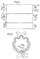
- Fig. 1 shows schematically a calender 1 with two end rolls 2, 3, which are designed as deflection rollers and three center rollers 4-6, which together form one Form the roll stack.
- the roll stack has a roll plane 7, in which the axes of all rollers 2 - 6 lie when the rollers 2 - 6 are arranged exactly one above the other are.
- this roller plane 7 lies for the
- press direction i.e. the direction in which the reels 2-6 pressed against each other.
- rollers 2 - 6 form during operation of the calender in known manner nips 10-13, through which one to be treated Material web is guided. All nips are here formed as so-called soft nips because they are from a hard and limited by a soft roller.
- Vibration transducers 20, 21, 22 (Fig. 2) arranged which vibrates the center rollers Determine 4 - 6.
- the vibration sensors 20 - 22 are preferably on the bearing 23, more precisely on the bearing housing 24 arranged.
- the vibration sensors determine this 20 vibrations in the vertical direction, the vibration sensor 21 vibrations perpendicular to Roller plane, i.e. the plane through the central axes of the (non-offset) rollers 2 - 6, and the vibration sensor 22 vibrations in the axial direction.
- the vibration sensors 20 - 22 in the Can basically determine any direction of vibration, as long as the directions are orthogonal to each other.
- the vibration sensors 20-22 are connected to one Regulator 25, which in turn is based on an adjustment drive 26 acts.
- the controller 25 also has a frequency analysis device 27 on that with a not shown Comparator and a threshold element coupled could be.
- the frequency analysis device 27 determined from the vibrations by the vibration sensors 20 - 22 are recorded, the amplitude Percentage of a frequency (or a narrow frequency range) can be assigned.
- the adjustment drive 26 in Operation set to cross the appropriate roller To adjust the press direction. This is schematic in Fig. 1 shown for the middle roller 5. It but it is obvious that basically all rollers 2 - 6 can be adjusted.
- the original barring pattern is one wavelength U / n, where U is the circumference of the roller 5, then has the new barring pattern may be a wavelength of U / (n ⁇ 1). Until such a new barring pattern but so far that it bothers some that passes Time.
- the aim here is a phase shift by the controller 25, which is closer to ⁇ / 2.
- the danger, connected with a phase shift of ⁇ / 2 is that after the initial pattern is canceled a new pattern is created by the Regulation counteracted.
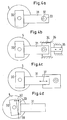
- Fig. 4 now shows different ways to To cause roll misalignment. The explanation is given in all cases using the example of the center roller 5, which in one Bearing housing 30 is mounted, which is on the front End of a lever 31 is located.
- the lever is 31st stored with a bearing point 32 in an eccentric sleeve 33. If the eccentric bushing 33 is rotated, then the position of the roller 5 changes in horizontal Direction.
- the lever 31 stored in a sliding block 34 which is in a housing 35 by a linear drive 36, which is only schematic is shown, can be moved in the housing 35.
- the linear drive can be used, for example, as a threaded spindle will be realized. Also with a threaded spindle relatively precise adjustment movements are possible.
- the lever is 31 adjustable in length, which is indicated by a double arrow 37 is shown.
- the lever 31 can for example have a telescopic or a prismatic guide.
- the drive of the two movable against each other Parts of the lever can also be threaded (not shown).
- a schematically represented Tilt drive 40 is provided around the bearing housing 30 compared to the lever 31 by a defined amount to tip.
Abstract
Es wird ein Verfahren zum Betreiben eines Kalanders und ein Kalander angegeben mit einem Walzenstapel (2-6), der zwei Endwalzen (2,3) und dazwischen mehrere Mittelwalzen (4-5) aufweist, die in einer Pressenrichtung (7) aneinander anliegen, wobei mindestens eine Walze (2,3,5) eine elastische Oberfläche (9) aufweist. Man möchte die Standzeit der Walzen mit elastischer Oberfläche verlängern. Hierzu ermittelt man bei mindestens einer Walze (5) fortlaufend eine Schwingung und nimmt einen Walzenversatz quer zur Pressenrichtung (7) in Abhängigkeit von der Schwingung vor. Hierzu ist ein Regler vorgesehen, mit dem Schwingungsaufnahmeeinrichtungen (20,21) verbunden sind und der wiederum mit einem Stellantrieb (26) an mindestens einer Walze verbunden ist. <IMAGE>The invention relates to a method for operating a calender and a calender with a roll stack (2-6) which has two end rolls (2, 3) and in between a plurality of middle rolls (4-5) which abut one another in a press direction (7). wherein at least one roller (2, 3, 5) has an elastic surface (9). One would like to extend the service life of the rollers with an elastic surface. For this purpose, a vibration is continuously determined in at least one roller (5) and a roller offset transversely to the press direction (7) is carried out as a function of the vibration. For this purpose, a controller is provided, to which vibration absorption devices (20, 21) are connected and which in turn is connected to an actuator (26) on at least one roller. <IMAGE>
Description
Die Erfindung betrifft ein Verfahren zum Betreiben eines Kalanders mit einem Walzenstapel, der zwei Endwalzen und dazwischen mehrere Mittelwalzen aufweist, die in einer Pressenrichtung aneinander anliegen, wobei mindestens eine Walze eine elastische Oberfläche aufweist. Ferner betrifft die Erfindung einen Kalander mit einem Walzenstapel, der zwei Endwalzen und dazwischen mehrere Mittelwalzen aufweist, wobei mindestens eine Walze eine elastische Oberfläche aufweist.The invention relates to a method for operating a Calender with a roll stack, the two end rolls and having a plurality of intermediate rolls therebetween abut each other in a press direction, whereby at least one roller has an elastic surface. The invention also relates to a calender a roll stack, the two end rolls and in between has a plurality of center rollers, at least one Roller has an elastic surface.
Derartige Kalander werden insbesondere zum Satinieren von Papier- oder Kartonbahnen verwendet. Die Erfindung wird im folgenden anhand der Behandlung einer Papierbahn beschrieben. Sie ist aber in gleicher Weise bei anderen Materialbahnen anwendbar, bei denen ähnliche Probleme auftreten. Calenders of this type are used in particular for calendering used by paper or cardboard webs. The invention is based on the treatment of a paper web described. But it is in the same way other material webs applicable, where similar Problems occur.
Beim Satinieren einer Papierbahn wird die Papierbahn durch den Kalander geleitet und in Nips, die zwischen einer harten und einer weichen Walze, d.h. einer Walze mit elastischer Oberfläche, gebildet sind, mit erhöhtem Druck und gegebenenfalls auch mit erhöhter Temperatur beaufschlagt. Bei Kalandern neuerer Bauart, beispielsweise den "Janus"-Kalandern, kommen Walzen zum Einsatz, die mit einem Kunststoffbelag bezogen sind. Man kann nun beobachten, daß es in vielen Fällen nach einer gewissen Betriebszeit zu Querstreifen auf der Papierbahn kommt. Sobald diese Streifen sichtbar werden, ist die Papierbahn unbrauchbar und bildet Ausschuß. Die Ursachen dieser sogenannten Barring-Bildung sind derzeit noch nicht restlos geklärt. Man nimmt aber an, daß es sich hierbei um Auswirkungen einer Schwingungserscheinung handelt. Schwingungen sind in einem Kalander aber praktisch unvermeidbar.When satinizing a paper web, the paper web becomes passed through the calender and into nips between a hard and a soft roller, i.e. a roller with elastic surface, are formed, with increased Pressure and possibly also at elevated temperature applied. For newer calenders, for example the "Janus" calenders, rollers are used, which are covered with a plastic covering. One can now observe that in many cases there is a certain Operating time for horizontal stripes on the paper web comes. As soon as these stripes become visible, the Paper web unusable and forms rejects. The reasons this so-called barring formation are currently not yet fully clarified. But one assumes that it concerns the effects of a vibration phenomenon is. Vibrations are in a calender though practically inevitable.
Bei der Barring-Bildung wird die weiche Walze verändert und zwar an ihrer elastischen Oberfläche. Es ist noch nicht abschließend geklärt, wie diese Veränderung genau aussieht. Man nimmt derzeit folgende Möglichkeiten an: Die Walze bekommt eine Welligkeit an der Oberfläche, d.h. eine Berg- und Talstruktur, die Walze wird vielekkig oder die Walze bekommt in Umfangsrichtung abwechselnd Zonen unterschiedlicher Oberflächengüte, beispielsweise unterschiedlicher Rauhigkeit. Unabhängig von der konkreten Art der Veränderung zeigen sich nach der Barring-Bildung periodische, in Axialrichtung verlaufende Streifen am Umfang der Walze. Entsprechende Streifen zeigen sich dann an der Papierbahn, wobei spätestens ab dem Sichtbarwerden der Streifen die Papierbahn als Ausschuß zu betrachten ist. When the barring is formed, the soft roller is changed on their elastic surface. It is still did not finally clarify exactly how this change looks. The following options are currently accepted: The roller gets a ripple on the surface, i.e. a mountain and valley structure, the roller becomes polygonal or the roller gets alternately in the circumferential direction Zones of different surface quality, for example different roughness. Independently the concrete nature of the change is evident the periodic barring formation, running in the axial direction Strip on the circumference of the roller. Appropriate Stripes then appear on the paper web, at the latest from the time the strips become visible the paper web is to be regarded as a committee.
Wenn eine Barring-Erscheinung auftritt, muß die Walze, die die Barring-Bildung verursacht, ausgebaut und überschliffen oder abgedreht werden. Die Standzeit einer derartigen Walze ist also begrenzt.If a barring phenomenon occurs, the roller, which causes, develops and grinds the barring formation or be turned off. The service life of one such roller is therefore limited.
Der Erfindung liegt die Aufgabe zugrunde, die Standzeit einer derartigen Walze zu erhöhen.The object of the invention is the service life to increase such a roller.
Diese Aufgabe wird bei einem Verfahren der eingangs genannten Art dadurch gelöst, daß man bei mindestens einer Walze fortlaufend eine Schwingung ermittelt und einen Walzenversatz quer zur Pressenrichtung in Abhängigkeit von der Schwingung vornimmt.This task is carried out in a method of the type mentioned at the beginning Art solved in that at least one Roll continuously determines a vibration and one Roll offset depending on the direction of the press of the vibration.
Man verwendet also eine Regelung, um die Ausbildung von Barring-Mustern zu verhindern. In der Regel läßt sich ein Barring-Muster auf der Oberfläche einer Walze schon feststellen, bevor sich dieses Barring-Muster in Form von Querstreifen in die Papierbahn einprägt. Wenn man also rechtzeitig Maßnahmen ergreift, um die stärkere Ausprägung des Barring-Musters zu stören, dann läßt sich die Standzeit der Walze erhöhen. Hierbei geht man von folgenden Überlegungen aus:So one uses a scheme to train To prevent barring patterns. As a rule, a barring pattern on the surface of a roller already notice before this barring pattern takes shape of horizontal stripes into the paper web. If So take timely action to get the stronger one Disturbing expression of the barring pattern, then lets the service life of the roller increases. Here you go based on the following considerations:
Ein Walzenstapel, der aus mehreren Walzen gebildet ist, hat eine Vielzahl von Eigenfrequenzen. Hierbei sind nicht die Eigenfrequenzen der einzelnen Walzen für sich, wie etwa Biegeeigenfrequenzen, gemeint, sondern die Eigenschwingungsformen, die sich aus den schwingenden Walzenmassen auf den Feder- und Dämpfersystemen der dazwischengeschalteten Kunststoffbeläge der "weichen" Walzen ergeben. Ein laufender Kalander erzeugt Erregerkräfte, deren Frequenzen sich aus dem Vielfachen der Walzendrehzahlen zusammensetzen. Diese Erregerkräfte können in Inhomogenitäten, Anisotropien oder Geometriefehlern (Unrundheiten) begründet sein. Ebenfalls können Papierdickenschwankungen der den Kalander durchlaufenden Papierbahn den Walzenstapel anregen. Eine in den Kalander einlaufende Papierbahn ist vor dem Glättprozeß noch sehr rauh. Zudem ist eine Papierbahn nie frei von Flächengewichts- bzw. Dickenschwankungen. Analysiert man diese Schwankungen mit Hilfe einer FFT-Analyse auf ihre Frequenzen, so stellt man in der Regel ein breitbandiges Rauschen fest, in dem sämtliche Frequenzen enthalten sind. Trifft eine dieser Erregerfrequenzen auf eine Eigenfrequenz, so antwortet das Schwingungssystem des Kalanders mit vergrößerten Schwingungsausschlägen. Aufgrund der Vielzahl der möglichen Erreger und der Vielzahl der möglichen Eigenschwingungsformen lassen sich diese Resonanzstellen konstruktiv nicht umgehen. In der Regel ist das Schwingungssystem auch so stark gedämpft und die Erregerkräfte sind so klein, daß die resultierenden Schwingbewegungen unmittelbar nicht störend sind. Über einen mehr oder weniger langen Zeitraum prägen sich diese Schwingbewegungen jedoch in die Kunststoffbeläge der elastischen Walzen ein.A stack of rolls made up of several rolls has a variety of natural frequencies. Here are not the natural frequencies of the individual rollers for itself, such as natural bending frequencies, but the natural vibration forms that result from the vibrating Roll masses on the spring and damper systems of the interposed plastic coverings of the "soft" Rolls result. A running calender creates excitation forces, whose frequencies are multiples of Assemble roller speeds. These excitation forces can inhomogeneities, anisotropies or geometry errors (Out of roundness). You can also Paper thickness fluctuations in the calender Excite the paper web the stack of rollers. One in the Calender incoming paper web is before the smoothing process still very rough. In addition, a paper web is never free of Surface weight or thickness fluctuations. analyzed these fluctuations with the help of an FFT analysis their frequencies, so you usually put a broadband Noise in which all frequencies are included. Strikes one of these excitation frequencies to a natural frequency, so the vibration system answers of the calender with increased vibrations. Because of the large number of possible pathogens and the multitude of possible natural vibrations these resonance points cannot be avoided constructively. The vibration system is usually the same strongly damped and the excitation forces are so small that the resulting vibratory movements are not immediate are disturbing. Over a more or less long period however, these oscillating movements are characterized in the Plastic coverings of the elastic rollers.
Üblicherweise werden die zur Eigenfrequenz nächstliegenden ganzzahligen Vielfachen der Walzendrehfrequenz als Muster auf den Walzen eingeprägt. Hierdurch erfolgt eine Rückkopplung der Schwingung. Die Schwingungsausschläge nehmen dann exponentiell zu. Sie äußern sich einerseits in einem erhöhten Schallpegel (bis mehr als 120 dB(A)) und andererseits in periodischen Dickenschwankungen der durchlaufenden Papierbahn. In der Praxis werden unterschiedliche Zeiträume beobachtet, in denen sich diese Rückkopplungserscheinungen, die sich in Barrings äußern, ausbilden. Meist vergehen einige Tage oder Wochen, bis diese Erscheinung so stark angewachsen ist, daß sie den Produktionsprozeß stört.Usually the closest to the natural frequency integer multiples of the roll rotation frequency embossed as a pattern on the rollers. This is done a feedback of the vibration. The vibration rashes then increase exponentially. You express yourself on the one hand in an increased sound level (up to more than 120 dB (A)) and on the other hand in periodic fluctuations in thickness the continuous paper web. In practice different periods are observed in who are experiencing these feedback phenomena express in barrings, train. Most of them pass Days or weeks until this phenomenon grew so much is that it disrupts the production process.
Man kann nun bereits relativ früh Maßnahmen ergreifen, die die Ausbildung von Barring-Mustern auf den elastischen Walzen verhindern oder stören. Hierzu werden lediglich Schwingungen ermittelt. Mit einer gewissen Erfahrung oder mit Maßnahmen, die weiter unten angegeben sind, kann man nun das Rückkoppelverhalten des Walzenstapels oder sogar des ganzen Kalanders verändern, so daß sich eine begonnene Ausbildung von Barring-Mustern zumindest nicht weiter vergrößert. In der Regel wird man bei einer gezielten Regelung, die auf die Schwingungen reagiert, eine Rückbildung der Barring-Muster erreichen können. Hierbei nimmt man zwar in Kauf, daß sich erneut Barring-Muster mit anderen Frequenzen ausbilden. Da aber die Regelung fortlaufend wirkt, kann man den Walzenversatz auch zu mehreren Zeitpunkten nacheinander durchführen, wobei die Zeitabstände zwischen zwei Verstellungen des Walzenversatzes durch den Schwingungszustand des Kalanders bestimmt sind.You can take action relatively early which the formation of barring patterns on the elastic Prevent or interfere with rollers. This will only be Vibrations determined. With some experience or with measures specified below are, you can now the feedback behavior of the roll stack or even change the whole calender, so that there is an ongoing formation of barring patterns at least not further enlarged. Usually will one with a targeted regulation based on the vibrations responds, a regression of the barring pattern reachable. Here you accept that Barring patterns are formed again with different frequencies. But since the regulation works continuously, can the roll offset also at several points in time Carry out one after the other, the time intervals between two adjustments of the roll offset by the Vibration condition of the calender are determined.
Vorzugsweise nimmt man den Walzenversatz vor, wenn die Schwingung eine Frequenz enthält, die einer von mehreren Vorgabefrequenzen entspricht. Die Schwingung, die man ermittelt, wird in der Regel ein breites Spektrum an Frequenzen enthalten, die unterschiedlichste Ursachen haben. Nicht zu vernachlässigen ist hierbei der Einfluß der Papierbahn, die nach dem Verlassen der Papiermaschine eine gewisse Oberflächenrauhigkeit hat und damit eine Anregung für die Schwingungen liefert. Von den Frequenzen sind jedoch nur einige wenige Frequenzen kritisch. Es reicht also aus, wenn man eine Frequenzanalyse der Schwingung vornimmt und "nachschaut", ob die kritischen Frequenzen enthalten sind. Da diese kritischen Frequenzen vorgegeben werden, werden sie als "Vorgabefrequenzen" bezeichnet.The roll offset is preferably carried out when the Vibration contains a frequency that is one of several Preset frequencies corresponds. The vibration that one usually finds a broad spectrum contain frequencies that have different causes to have. Not to be neglected here Influence of paper web after leaving the paper machine has a certain surface roughness and thus providing an excitation for the vibrations. Of However, the frequencies are only a few frequencies critical. So it is enough if you do a frequency analysis makes the vibration and "checks" whether the critical frequencies are included. Because these are critical Frequencies are given as "Specification frequencies" referred to.
Vorzugsweise wird ein Versatz vorgenommen, wenn der Anteil mit der Frequenz eine vorbestimmte Amplitude überschreitet. Auch kritische Frequenzen sind nicht in jedem Fall von Anfang an störend. Sie sind, wenn sie mit kleiner Amplitude auftreten, lediglich ein Warnsignal. Man kann nun eine gewisse Toleranzschwelle vorsehen und einen Versatz nur dann vornehmen, wenn eine vorbestimmte Amplitude überschritten wird. Man riskiert dabei zwar, daß Barring-Muster anfangen, sich auszubilden. Der Betrieb des Kalanders wird dann aber weniger oft verändert, wodurch weitere Störungsmöglichkeiten klein gehalten werden.An offset is preferably made when the portion with the frequency exceeds a predetermined amplitude. Even critical frequencies are not in everyone Case disturbing from the start. They are when with small amplitude occur, only a warning signal. You can now provide a certain tolerance threshold and make an offset only when a predetermined one Amplitude is exceeded. You risk it that barring patterns are starting to develop. The operation of the calender then becomes less frequent changed, making further malfunctions small being held.
Vorzugsweise existiert zu jeder Vorgabefrequenz eine Wellenlänge, die einem ganzzahligen Bruchteil des Umfangs einer Walze entspricht. Wenn man die Barring-Muster auf der Oberfläche einer Walze analysiert, stellt man fest, daß es sich hierbei um ein Wellenmuster handelt, bei dem die Wellenlänge einem ganzzahligen Bruchteil des Walzenumfangs entspricht. Barring-Muster mit anderen Wellenlängen wird man nicht beobachten können, weil sich bei diesen anderen Barring-Mustern laufend eine Umformung ergeben müßte, die eine endgültige Ausbildung eines derartigen Barring-Musters verhindert. Bei Barring-Mustern, bei denen ein ganzzahliges Vielfaches der Wellenlänge genau den Umfang der Walze ergibt, ist dieses Auslöschen nicht gegeben. Man kann aber jedem dieser Barring-Muster eine bestimmte Frequenz zuordnen, die u.a. auch von der Umfangsgeschwindigkeit der betreffenden Walze abhängt. Auf diese Weise ist es relativ einfach, die Vorgabefrequenzen zu errechnen.There is preferably one for each default frequency Wavelength that is an integer fraction of the circumference corresponds to a roller. If you look at the barring pattern analyzed on the surface of a roller, one finds that this is a wave pattern where the wavelength is an integer Fraction of the roll circumference corresponds. Barring pattern you will not observe at other wavelengths can because of these other barring patterns should constantly result in a transformation, the one final formation of such a barring pattern prevented. For barring patterns where an integer Multiples of the wavelength exactly the scope of the Roller results, there is no such extinction. you but each of these barring patterns can have a specific one Assign frequency that also from the peripheral speed depends on the roller in question. To this Way it is relatively easy to set the default frequencies calculate.
Vorzugsweise ermittelt man zumindest an jeder Mittelwalze die Schwingung und beschränkt die Vorgabefrequenzen auf Wellenlängen, die an der entsprechenden Walze auftreten. Diese Vorgehensweise hat mehrere Vorteile. Zum einen ist die Schwingung, die an einer Walze auftritt, mit wesentlich geringeren Dämpfungen unmittelbar an dieser Walze abnehmbar als an anderen Walzen. Die Information über die Walzenschwingung steht also unmittelbarer zur Verfügung. Zum anderen muß man eine wesentlich geringere Anzahl von Vorgabefrequenzen beachten. Dies gilt insbesondere dann, wenn die Walzen des Walzenstapels unterschiedliche Umfänge aufweisen. Diese Situation tritt aber in der Regel auf, insbesondere dann, wenn eine oder mehrere Walzen mit elastischen Belägen bereits einmal überarbeitet worden sind. In diesem Fall vermindert man den Verarbeitungsaufwand, da nur weniger Informationen ausgewertet werden müssen. Die Regelung kann dann schneller erfolgen.It is preferable to determine at least on each center roll the vibration and limits the default frequencies at wavelengths that are on the corresponding roller occur. This approach has several advantages. First, the vibration that occurs on a roller with much lower damping immediately removable on this roller than on other rollers. The Information about the roller vibration is therefore more immediate to disposal. On the other hand, one has to be essential Note the lower number of default frequencies. This is especially true when the rollers of the Roll stack have different sizes. This However, situation usually occurs, especially then when one or more rollers with elastic coverings have already been revised once. In this In this case, the processing effort is reduced because less information needs to be evaluated. The regulation can then take place more quickly.
Vorzugsweise versetzt man die Walze um eine Strecke, die von der Wellenlänge der Frequenz abhängt. Da über die ermittelte Frequenz die Wellenlänge des Barring-Musters bekannt ist, kann man nun diese Information auswerten und die Walze quer zur Pressenrichtung um einen Betrag versetzen, in den diese Wellenlängeninformation einfließt. Dabei kann man erreichen, daß bei bestimmten Versatz-Strecken eine Ausbildung des Barring-Musters rückgängig gemacht wird. Bei abweichenden Versatz-Strecken kann eine weitere Ausbildung des Barring-Musters zumindest gehemmt werden.Preferably, you move the roller a distance, which depends on the wavelength of the frequency. Over there the frequency determined is the wavelength of the barring pattern is known, you can now get this information evaluate and the roller across the press direction by one Offset amount in which this wavelength information flows. You can achieve that with certain Offset stretches a formation of the barring pattern undone. In the case of deviating offset distances may further develop the barring pattern at least be inhibited.
Hierbei ist besonders bevorzugt, daß man die Walze um eine Strecke versetzt, bei der ein Weglängenunterschied zwischen zwei Nips entsteht, der im Bereich von einer viertel bis einer halben Wellenlänge liegt. Würde man einen Walzenversatz vornehmen, bei dem der Weglängenunterschied genau eine Wellenlänge beträgt, hätte man sicherlich keinen positiven Effekt. Bei längeren Weglängenunterschieden müßte man die Walze entsprechend weiter versetzen, wobei man das Risiko in Kauf nehmen müßte, eine ungünstige Änderung der Geometrie des Walzenstapels zu erhalten. Wenn man hingegen den Versatz auf relativ kurze Weglängenunterschiede zwischen einer viertel und einer halben Wellenlänge beschränkt, dann hat man auch einen entsprechend kleinen Versatz der Walze quer zur Pressenrichtung und erhält trotzdem den vorteilhaften Effekt, daß sich die Barring-Muster zurückbilden oder zumindest nicht weiter ausprägen.It is particularly preferred that the roller offset a route where there is a path length difference between two nips, the one in the range quarter to half a wavelength. You would make a roll offset in which the path length difference one wavelength would certainly be no positive effect. With longer path length differences you would have to continue the roller accordingly move, taking the risk, an unfavorable change in the geometry of the roll stack to obtain. However, if you set the offset on relatively short path length differences between one limited to a quarter and a half wavelength, then you also have a correspondingly small offset of the Roll across the press direction and still receives the advantageous effect that the barring patterns recede or at least not further.
Vorzugsweise versetzt man die Walze um eine Strecke, die im Bereich von einer achtel bis einer viertel Wellenlänge liegt. Dies gilt bei Mittelwalzen, bei denen die Walzenoberfläche bei einer Umdrehung zwei Nips durchläuft. Um einen Weglängenunterschied auf der Oberfläche zwischen zwei Nips von einer viertel oder einer halben Wellenlänge zu bewirken, ist es dann lediglich erforderlich, die Walze um die Hälfte des Weglängenunterschiedes zu versetzen. Dann wird auf der einen Walzenseite der Weglängenunterschied um das Doppelte des Walzenversatzes vergrößert, während er auf der anderen Seite der Walze um das Doppelte der Versatzstrecke verkleinert wird. Wenn man also den Weglängenunterschied um eine viertel Wellenlänge ändern will, ist lediglich eine Versatzbewegung um eine achtel Wellenlänge erforderlich. Die Versatzbewegung beschränkt sich daher auf eine Länge in der Größenordnung von 10 mm.Preferably, you move the roller a distance, that are in the range of one eighth to one quarter wavelength lies. This applies to center rolls where the roll surface two nips in one revolution passes. By a path length difference on the surface between two nips of a quarter or one half wavelength, it is then only required, the roller by half the path length difference to move. Then on one side of the roller the path length difference by twice the Roll misalignment increased while on the other Side of the roller reduced by twice the offset distance becomes. So if you look at the path length difference want to change by a quarter wavelength is just an offset movement of an eighth wavelength is required. The offset movement is therefore limited to a length of the order of 10 mm.
Die Aufgabe wird bei einem Kalander der eingangs genannten Art dadurch gelöst, daß an mindestens einer Walze eine Schwingungsaufnahmeeinrichtung angeordnet ist, die mit einem Regler verbunden ist, der mit einem Verstellantrieb mindestens einer Walze verbunden ist.The task is with a calender of the aforementioned Art solved in that at least one Roller arranged a vibration pickup which is connected to a controller which is connected to a Adjustment drive is connected to at least one roller.
Man etabliert also einen Regelkreis, der eine Walze in Abhängigkeit von Schwingungen verstellt, die an dieser oder einer anderen Walze auftreten. Man ist also nicht mehr auf eine zufällige Verstellung nach dem Prinzip des Probierens angewiesen. Auch muß man die Walzen nicht fortlaufend verstellen, um die Schwingungsausbildung an irgendeinem Betriebspunkt zu unterbinden. Man kontrolliert vielmehr, ob sich Schwingungen bestimmter Art ausbilden. Wenn sich derartige Schwingungen ausbilden, greift der Regler ein und verstellt über den Verstellantrieb die Walze.So you establish a control loop that a roller in Dependence on vibrations adjusted on this or another roller. So you are not more on a random adjustment according to the principle instructed to try. You also have to use the rollers do not adjust continuously to the vibration training prevent at any operating point. you rather controls whether vibrations are certain Train kind. If such vibrations develop, the controller intervenes and adjusts via the adjustment drive the roller.
Hierbei ist bevorzugt, daß die Schwingungsaufnahmeeinrichtung mit einer Frequenzanalyseeinrichtung verbunden ist. Die Frequenzanalyseeinrichtung stellt fest, welche Frequenzen in der Schwingung enthalten sind. Wie oben ausgeführt, sind nicht alle Frequenzen kritisch. Man kann also die Tätigkeit des Reglers auf bestimmte Frequenzen beschränken. It is preferred that the vibration pickup device connected to a frequency analysis device is. The frequency analysis device determines which Frequencies contained in the vibration. As above not all frequencies are critical. you So can the activity of the controller on certain frequencies restrict.
Vorzugsweise weist die Schwingungsaufnahmeeinrichtung mehrere Schwingungsaufnehmer auf, die auf unterschiedliche Richtungen ausgerichtet sind. Man kann dadurch die auszuwertende Information verdichten. Schwingungen, die beispielsweise ihre Hauptschwingungsrichtung parallel zur Axialrichtung der Walzen haben, sind für die Barring-Bildung weniger kritisch als Schwingungen, die radial zur Walzenachse gerichtet sind.Preferably, the vibration pickup device several vibration sensors based on different Directions are aligned. You can do it condense the information to be evaluated. vibrations which, for example, their main vibration direction parallel for the axial direction of the rollers are for the Barring formation is less critical than vibrations are directed radially to the roller axis.
Vorzugsweise ist die Schwingungsaufnahmeeinrichtung zumindest an jeder Mittelwalze angeordnet. Man ermittelt also die Schwingungen an jeder Mittelwalze. Dies hat den Vorteil, daß man zum einen die Schwingung jeder Mittelwalze an der Mittelwalze selbst feststellen kann, so daß sie nicht durch einen Übertragungsweg über andere Walzen gedämpft oder sogar verfälscht worden ist. Zum anderen kann man sich bei der Auswertung auf die kritischen Frequenzen beschränken, die an der speziellen Walze auftreten können. Schließlich läßt sich dann, wenn die Schwingung an jeder Walze, zumindest an jeder Mittelwalze, einzeln ermittelt wird, gezielter eine Maßnahme treffen, um die Ausbildung eines Barring-Musters an jeder Walze zu verhindern.The vibration-absorbing device is preferably at least arranged on each center roll. One determines so the vibrations on each center roll. this has the advantage that you have the vibration of everyone Middle roller on the middle roller itself can determine so that it is not through a transmission path through others Rolling has been dampened or even falsified. On the other hand, you can rely on the evaluation limit critical frequencies at the particular Roller can occur. Finally, if the vibration on each roller, at least on each Center roll, determined individually, more targeted one Take action to form a barring pattern to prevent on each roller.
Vorzugsweise sind zumindest die Mittelwalzen an Hebeln angeordnet und der Verstellantrieb wirkt auf den Hebel. Dies ist eine relativ einfache Maßnahme, um den Versatz der jeweiligen Walze senkrecht zur Pressenrichtung zu bewirken.At least the middle rollers are preferably on levers arranged and the adjustment drive acts on the lever. This is a relatively simple measure to offset of the respective roller perpendicular to the direction of the press cause.
Für die Ausbildung des Verstellantriebs gibt es nun eine Reihe von Möglichkeiten. There is now one for the training of the adjustment drive Number of possibilities.
In einer bevorzugten Ausführungsform ist vorgesehen, daß der Verstellantrieb eine Exzenterbüchse aufweist, in der ein Lagerpunkt des Hebels angeordnet ist. Durch ein Verdrehen der Exzenterbüchse um eine Achse, die parallel zur Walzenachse verläuft, läßt sich ein Lagerpunkt des Hebels, beispielsweise der Drehpunkt, relativ zur Pressenrichtung verändern.In a preferred embodiment, that the adjustment drive has an eccentric bush, in which a bearing point of the lever is arranged. By a twisting of the eccentric sleeve around an axis that A bearing point can be run parallel to the roller axis the lever, for example the fulcrum, relative change to press direction.
In einer alternativen Ausgestaltung ist vorgesehen, daß der Hebel in einem Kulissenstein gelagert ist, der einen Linearantrieb aufweist. Der Linearantrieb bewirkt zunächst eine translatorische Verschiebung des Kulissensteins, beispielsweise mit Hilfe einer Gewindespindel. Der Kulissenstein nimmt dabei den Hebel mit, so daß die Walze letztendlich wieder senkrecht zur Pressenrichtung verlagert werden kann.In an alternative embodiment it is provided that the lever is stored in a sliding block that one Has linear drive. The linear drive works first a translational shift of the sliding block, for example with the help of a threaded spindle. The sliding block takes the lever with it, so that the roller is finally perpendicular to the direction of the press can be relocated.
Schließlich kann auch vorgesehen sein, daß der Hebel längenveränderbar ausgebildet ist. Eine derartige Ausbildung läßt sich beispielsweise durch eine Teleskopoder eine Prismenführung realisieren, bei der zwei Bestandteile des Hebels relativ zueinander verschoben werden.Finally, it can also be provided that the lever is designed to be variable in length. Such training can, for example, by a telescopic or implement a prismatic guide in which two components of the lever shifted relative to each other become.
In einer weiteren alternativen Ausgestaltung kann vorgesehen sein, daß zwischen dem Hebel und einem Lagergehäuse eine Gelenkverbindung mit einem Kippantrieb vorgesehen ist. Damit lassen sich relativ genau Versatzbewegungen der Walze einstellen.In a further alternative embodiment, provision can be made be that between the lever and a bearing housing an articulated connection is provided with a tilt drive is. This makes it possible to offset movements relatively precisely adjust the roller.
Die Erfindung wird im folgenden anhand von bevorzugten Ausführungsbeispielen in Verbindung mit der Zeichnung beschrieben. Hierin zeigen:
- Fig. 1
- eine schematische Darstellung eines Kalanders von der Seite,
- Fig. 2
- einen Ausschnitt der Darstellung des Kalanders nach Fig. 1 von vorne,
- Fig. 3
- eine schematische Darstellung zur Erläuterung der Ausbildung eines Barring-Musters und
- Fig. 4
- verschiedene Möglichkeiten zum Versatz einer Walze.
- Fig. 1
- a schematic representation of a calender from the side,
- Fig. 2
- 1 shows a section of the representation of the calender according to FIG. 1 from the front,
- Fig. 3
- a schematic representation for explaining the formation of a barring pattern and
- Fig. 4
- different ways to offset a roller.
Fig. 1 zeigt schematisch einen Kalander 1 mit zwei Endwalzen
2, 3, die als Durchbiegungswalzen ausgebildet
sind, und drei Mittelwalzen 4 - 6, die zusammen einen
Walzenstapel bilden. Der Walzenstapel weist eine Walzenebene
7 auf, in der die Achsen aller Walzen 2 - 6
liegen, wenn die Walzen 2 - 6 exakt übereinander angeordnet
sind. In dieser Walzenebene 7 liegt für die
Zwecke der nachfolgenden Beschreibung auch die Pressenrichtung,
d.h. die Richtung, in der die Walzen 2 - 6
gegeneinander gedrückt werden.Fig. 1 shows schematically a calender 1 with two end rolls
2, 3, which are designed as deflection rollers
and three center rollers 4-6, which together form one
Form the roll stack. The roll stack has a
Weitere Einzelheiten des Kalanders sind nur schematisch
dargestellt, wie ein Antrieb 8, oder ganz weggelassen,
wie Mittel zur Beheizung von einzelnen Walzen. Die beiden
Endwalzen 2, 3 und die mittlerste Walze 5 weisen
aber einen elastischen Belag 9 auf, der übertrieben
dick dargestellt ist.Further details of the calender are only schematic
shown as a
Die Walzen 2 - 6 bilden beim Betrieb des Kalanders in bekannter Weise Nips 10 - 13, durch die eine zu behandelnde Materialbahn geführt wird. Alle Nips sind hier als sogenannte weiche Nips ausgebildet, da sie von einer harten und von einer weichen Walze begrenzt werden.The rollers 2 - 6 form during operation of the calender in known manner nips 10-13, through which one to be treated Material web is guided. All nips are here formed as so-called soft nips because they are from a hard and limited by a soft roller.
An den Zwischenwalzen sind Schwingungsaufnehmer 20, 21,
22 (Fig. 2) angeordnet, die eine Schwingung der Mittelwalzen
4 - 6 ermitteln. Die Schwingungsaufnehmer 20 -
22 sind vorzugsweise am Lager 23, genauer gesagt am Lagergehäuse
24 angeordnet. Hierbei ermitteln die Schwingungsaufnehmer
20 Schwingungen in vertikaler Richtung,
die Schwingungsaufnehmer 21 Schwingungen senkrecht zur
Walzenebene, d.h. der Ebene durch die Mittelachsen der
(unversetzten) Walzen 2 - 6, und der Schwingungsaufnehmer
22 Schwingungen in axialer Richtung. Allgemein kann
man sagen, daß die Schwingungsaufnehmer 20 - 22 im
Grunde beliebige Schwingungsrichtungen ermitteln können,
solange die Richtungen orthogonal zueinander stehen.
Die Schwingungsaufnehmer 20 - 22 sind verbunden mit einem
Regler 25, der wiederum auf einen Verstellantrieb
26 einwirkt. Der Regler 25 weist noch eine Frequenzanalyseeinrichtung
27 auf, die mit einem nicht näher dargestellten
Komparator und einem Schwellwertelement gekoppelt
sein können. Die Frequenzanalyseeinrichtung 27
ermittelt aus den Schwingungen, die von den Schwingungsaufnehmern
20 - 22 aufgenommen werden, den amplitudenmäßigen
Anteil, der jeweils einer Frequenz (oder
einem engen Frequenzbereich) zugeordnet werden kann.
Wenn die Amplitude einer Frequenz einen vorbestimmten
Grenz- oder Schwellwert überschreitet und diese Frequenz
als kritisch angesehen werden kann, weil sie mit
einer Wellenlänge in Beziehung gesetzt wird, deren
ganzzahliges Vielfaches dem Umfang der entsprechenden
Walze entspricht, dann wird der Verstellantrieb 26 in
Betrieb gesetzt, um die entsprechende Walze quer zur
Pressenrichtung zu verstellen. Dies ist in Fig. 1 schematisch
für die mittlerste Walze 5 dargestellt. Es
liegt aber auf der Hand, daß im Grunde alle Walzen 2 -
6 verstellt werden können.The vibration sensors 20-22 are connected to one
Man kann nun beobachten, daß sich nach einem Walzenversatz um die Strecke X das Schwingungsverhalten der Walzen ändert. Besonders günstige Verhältnisse ergeben sich dann, wenn man bei der Versatzbewegung X bestimmte Randbedingungen beachtet, die im folgenden anhand von Fig. 3 erläutert werden sollen.One can now observe that after a roll misalignment around the distance X the vibration behavior of the rollers changes. Particularly favorable conditions result if you determined X in the offset movement Boundary conditions observed, which are based on Fig. 3 are to be explained.
In Fig. 3 dargestellt sind die Walze 5, die darüber befindliche
Walze 4 und die darunter befindliche Walze 6.
Mit übertrieben großen Amplituden sind verschiedene Bezugswelligkeiten
dargestellt und zwar eine Welligkeit,
bei der sieben Wellen um den Umfang der Walze 5 herumlaufen,
eine mit acht Wellen und eine mit neun Wellen.
Die Anzahlen n = 7, 8, 9 wurden aus Gründen der Übersicht
gewählt. Bei realen Walzen werden sich über den
Umfang der Walze entsprechend mehr Wellen einstellen,
beispielsweise in der Größenordnung von 30 bis 50. Bei
derart vielen Wellen, die um den Umfang der Walze 5
verlaufen, kann man in erster Näherung davon ausgehen,
daß bei einer kleinen Versatzbewegung der Walze 5 gegenüber
der Walzenebene 7, die kleiner ist als eine
Wellenlänge, die Krümmung der Walze 5 keine Rolle
spielt.3 shows the
Wenn der Regler 25 nun ermittelt hat, daß eine kritische
Frequenz, die man entweder vorher aus Erfahrungswerten
vorgegeben oder auf sonstige Weise ermittelt
hat, mit einer vorbestimmten Amplitude auftritt, dann
ist zu erwarten, daß zu dieser Frequenz auch eine bestimmte
Wellenlänge λ gehört, mit der sich das Barring-Muster
an der Oberfläche der Walze ausprägt. Man versetzt
dann die Walze 5 gegenüber der Walzenebene 7,
d.h. gegenüber den Nips 11, 12 so, daß die Entfernung
zwischen den beiden Nips 11, 12 auf der einen Seite um
eine halbe Wellenlänge λ/2 vergrößert und auf der anderen
Seite um diese halbe Wellenlänge λ/2 verkleinert
wird. Hierzu ist lediglich ein Versatz X erforderlich,
der X = λ/4 entspricht, weil sich dadurch der gewünschte
Weglängenunterschied zwischen den beiden Nips 11, 12
ergibt.If the
Bei einem Weglängenunterschied von λ/2 entsteht an den
Punkten des Umfangs der Walze 5, die zuvor stark belastet
worden sind und wo sich dementsprechend Wellentäler
ausgebildet haben, keine Belastung. Diese Belastung
entsteht vielmehr an den Wellenbergen, an denen bisher
die entsprechende Belastung gefehlt hat. Die Belastungen
ergeben sich durch die Schwingungsbewegungen der
drei Walzen 4, 5, 6 relativ zueinander. Man kann durch
einen Weglängenunterschied von λ/2 also erreichen, daß
sich ein bereits ausgebildetes Barring-Muster wieder
umprägt und im Laufe der Zeit verschwindet. Man riskiert
dabei zwar, daß sich ein anderes Barring-Muster
ausbildet, dessen Wellenlänge in der Nähe der Wellenlänge
des ursprünglichen Barring-Musters liegt. Wenn
also das ursprüngliche Barring-Muster eine Wellenlänge
U/n hatte, wobei U der Umfang der Walze 5 ist, dann hat
das neue Barring-Muster möglicherweise eine Wellenlänge
von U/(n ± 1). Bis ein derartiges neues Barring-Muster
aber so weit ausgeprägt ist, daß es stört, vergeht einige
Zeit.With a path length difference of λ / 2 arises at
Points of the circumference of the
Eine Verminderung der Rückkopplung kann bereits bei einer
Phasenverschiebung zwischen zwei Nips 11, 12 von
X = λ/4 erreicht werden. Da sowohl für die Rückkopplung
durch die Materialbahn als auch für die Rückkopplung
über die Walzenoberfläche eine Verminderung bzw. Auslöschung
der Störung erreicht werden soll, sollte eine
Verschiebung gewählt werden, bei der sowohl die Phasenverschiebung
für das Papier als auch die Phasenverschiebung
für die Walze im Bereich von λ/4 bis λ/2
liegt. Angestrebt wird hier eine Phasenverschiebung
durch den Regler 25, die näher bei λ/2 liegt. Der Gefahr,
die mit einer Phasenverschiebung von λ/2 verbunden
ist, nämlich daß sich nach dem Auslöschen des Anfangsmusters
ein neues Muster ausprägt, wird durch die
Regelung entgegengewirkt. Sobald mit Hilfe der Schwingungsmessung
Einprägungsfrequenzen mit vorbestimmten
Amplituden erkennbar werden, wobei diese Amplituden
auch relativ klein sein können, wird ein neuer Walzenversatz
ermittelt und eingestellt, der wiederum eine
Auslöschung bewirkt. Die Zeitabstände zwischen zwei
Verstellungen des Walzenversatzes sind demnach durch
den Schwingungszustand des Kalanders bestimmt.A reduction in the feedback can already occur with one
Phase shift between two
Fig. 4 zeigt nun verschiedene Möglichkeiten, um den
Walzenversatz zu bewirken. Die Erläuterung erfolgt in
allen Fällen am Beispiel der Mittelwalze 5, die in einem
Lagergehäuse 30 gelagert ist, das sich am vorderen
Ende eines Hebels 31 befindet. Fig. 4 now shows different ways to
To cause roll misalignment. The explanation is given in
all cases using the example of the
Beim Ausführungsbeispiel nach Fig. 4a ist der Hebel 31
mit einem Lagerpunkt 32 in einer Exzenterbüchse 33 gelagert.
Wenn die Exzenterbüchse 33 verdreht wird, dann
ändert sich die Position der Walze 5 in horizontaler
Richtung.4a, the lever is 31st
stored with a
Beim Ausführungsbeispiel nach Fig. 4b ist der Hebel 31
in einem Kulissenstein 34 gelagert, der in einem Gehäuse
35 durch einen Linearantrieb 36, der nur schematisch
dargestellt ist, im Gehäuse 35 verschoben werden kann.
Der Linearantrieb kann beispielsweise als Gewindespindel
realisiert werden. Auch mit einer Gewindespindel
sind relativ genaue Verstellbewegungen möglich.In the embodiment according to FIG. 4b, the
Im Ausführungsbeispiel nach Fig. 4c ist der Hebel 31
längenveränderbar ausgebildet, was durch einen Doppelpfeil
37 dargestellt ist. Der Hebel 31 kann beispielsweise
eine Teleskop- oder eine Prismenführung aufweisen.
Der Antrieb der beiden gegeneinander verschiebbaren
Teile des Hebels kann ebenfalls über eine Gewindespindel
(nicht näher dargestellt) erfolgen.In the exemplary embodiment according to FIG. 4c, the lever is 31
adjustable in length, which is indicated by a
Beim Ausführungsbeispiel nach Fig. 4d ist das Lagergehäuse
30 über ein Drehgelenk 38 mit dem Hebel 31 verbunden.
Das Drehgelenk 38 ist am unteren Ende einer Befestigungsplatte
39 angeordnet, die wiederum am Hebel
31 befestigt ist. Eine Anbringung am oberen Ende ist
selbstverständlich auch möglich. Ein schematisch dargestellter
Kippantrieb 40 ist vorgesehen, um das Lagergehäuse
30 gegenüber dem Hebel 31 um ein definiertes Maß
zu kippen.4d is the bearing
Claims (17)
Applications Claiming Priority (2)
| Application Number | Priority Date | Filing Date | Title |
|---|---|---|---|
| DE10133888 | 2001-07-12 | ||
| DE10133888A DE10133888C1 (en) | 2001-07-12 | 2001-07-12 | Operation of roller stack including resiliently-surfaced roller which can be offset transversely with respect to pressing direction |
Publications (2)
| Publication Number | Publication Date |
|---|---|
| EP1275774A1 true EP1275774A1 (en) | 2003-01-15 |
| EP1275774B1 EP1275774B1 (en) | 2007-01-03 |
Family
ID=7691527
Family Applications (1)
| Application Number | Title | Priority Date | Filing Date |
|---|---|---|---|
| EP02014376A Expired - Fee Related EP1275774B1 (en) | 2001-07-12 | 2002-06-28 | Process for operating a calender and calender |
Country Status (4)
| Country | Link |
|---|---|
| US (1) | US6857356B2 (en) |
| EP (1) | EP1275774B1 (en) |
| CA (1) | CA2393248C (en) |
| DE (2) | DE10133888C1 (en) |
Families Citing this family (9)
| Publication number | Priority date | Publication date | Assignee | Title |
|---|---|---|---|---|
| FI20030377A0 (en) * | 2003-03-13 | 2003-03-13 | Metso Paper Inc | Method of calendering and calender |
| DE10343980B4 (en) * | 2003-09-19 | 2005-08-18 | Eduard Küsters Maschinenfabrik GmbH & Co. KG | calender |
| FI115984B (en) * | 2003-11-27 | 2005-08-31 | Metso Paper Inc | Method and arrangement for preventing oscillation in a multi-nip calender or calender array |
| FI117301B (en) * | 2005-02-11 | 2006-08-31 | Metso Paper Inc | Storage of a web processing machine's roller and method of damping the roll vibration |
| FI118812B (en) | 2006-02-01 | 2008-03-31 | Metso Paper Inc | Method for Controlling the Specific Vibration Frequency of a Calender Intermediate Roll and Vibration Dampener |
| FI119851B (en) | 2007-09-28 | 2009-04-15 | Metso Paper Inc | Method for attenuating periodic vibration of a fiber web machine |
| FI119335B (en) | 2007-09-28 | 2008-10-15 | Metso Paper Inc | Multiple choice Calendar |
| JP5123654B2 (en) * | 2007-12-11 | 2013-01-23 | 住友化学株式会社 | Method for producing extruded resin plate |
| DE102010002703A1 (en) * | 2010-03-09 | 2011-09-15 | Metso Paper, Inc. | Arrangement for regulating force in gap between two rollers in paper- or cardboard machine, has spring rate changing units for changing spring rate of rolling system under retention of force between rollers and position of one of rollers |
Citations (5)
| Publication number | Priority date | Publication date | Assignee | Title |
|---|---|---|---|---|
| US3044392A (en) * | 1959-07-10 | 1962-07-17 | Kimberly Clark Co | Papermaking machine |
| WO1999025921A1 (en) * | 1997-11-17 | 1999-05-27 | Valmet Corporation | Method for detecting contamination and/or damaging of a face that runs through a nip or nips in a calender for paper |
| US5961899A (en) * | 1997-07-15 | 1999-10-05 | Lord Corporation | Vibration control apparatus and method for calender rolls and the like |
| EP0949378A1 (en) * | 1998-04-06 | 1999-10-13 | Voith Sulzer Papiertechnik Patent GmbH | Roller machine and method of operating the same |
| EP1127977A2 (en) * | 2000-02-25 | 2001-08-29 | Voith Paper Patent GmbH | Method for operating a calander roll and calander roll |
Family Cites Families (8)
| Publication number | Priority date | Publication date | Assignee | Title |
|---|---|---|---|---|
| NL299751A (en) * | 1962-10-26 | |||
| FI64902C (en) * | 1976-03-30 | 1984-02-10 | Wiik & Hoeglund | COMPENSATION FOR COMPENSATION OF VALUES AND ENVIRONMENT |
| US4348952A (en) * | 1981-01-19 | 1982-09-14 | Usm Corporation | Cross axis mechanism |
| US4516491A (en) | 1983-09-30 | 1985-05-14 | Usm Corporation | Roll cross-axis mechanism |
| GB2161105B (en) * | 1984-07-04 | 1988-06-15 | Fred Whitehead | Calendar or roll assembly |
| DE4314653C2 (en) | 1993-05-04 | 1997-01-30 | Troester Maschf Paul | Multi-purpose calender |
| DE19601293C2 (en) | 1996-01-16 | 1999-09-16 | Voith Sulzer Finishing Gmbh | Method and device for treating a material web |
| DE19832067B4 (en) | 1998-07-16 | 2005-04-21 | Voith Paper Patent Gmbh | Calender for webs of paper or similar material |
-
2001
- 2001-07-12 DE DE10133888A patent/DE10133888C1/en not_active Expired - Fee Related
-
2002
- 2002-06-28 DE DE50209131T patent/DE50209131D1/en not_active Expired - Lifetime
- 2002-06-28 EP EP02014376A patent/EP1275774B1/en not_active Expired - Fee Related
- 2002-07-11 US US10/192,499 patent/US6857356B2/en not_active Expired - Fee Related
- 2002-07-11 CA CA002393248A patent/CA2393248C/en not_active Expired - Fee Related
Patent Citations (5)
| Publication number | Priority date | Publication date | Assignee | Title |
|---|---|---|---|---|
| US3044392A (en) * | 1959-07-10 | 1962-07-17 | Kimberly Clark Co | Papermaking machine |
| US5961899A (en) * | 1997-07-15 | 1999-10-05 | Lord Corporation | Vibration control apparatus and method for calender rolls and the like |
| WO1999025921A1 (en) * | 1997-11-17 | 1999-05-27 | Valmet Corporation | Method for detecting contamination and/or damaging of a face that runs through a nip or nips in a calender for paper |
| EP0949378A1 (en) * | 1998-04-06 | 1999-10-13 | Voith Sulzer Papiertechnik Patent GmbH | Roller machine and method of operating the same |
| EP1127977A2 (en) * | 2000-02-25 | 2001-08-29 | Voith Paper Patent GmbH | Method for operating a calander roll and calander roll |
Non-Patent Citations (2)
| Title |
|---|
| M. HERMANSKI: "Barringbildung am Glättkalander einer Papiermaschine", DAS PAPIER, no. 9, 1995, pages 581 - 590, XP001118222 * |
| Y.N. CHEN ET.AL.: "Calender barring on paper machines-practical conclusions and recommendations", TAPPI JOURNAL, vol. 58, no. 8, 1975, pages 147 - 151, XP002216957 * |
Also Published As
| Publication number | Publication date |
|---|---|
| DE10133888C1 (en) | 2002-11-28 |
| US20030024415A1 (en) | 2003-02-06 |
| US6857356B2 (en) | 2005-02-22 |
| DE50209131D1 (en) | 2007-02-15 |
| CA2393248A1 (en) | 2003-01-12 |
| CA2393248C (en) | 2007-12-18 |
| EP1275774B1 (en) | 2007-01-03 |
Similar Documents
| Publication | Publication Date | Title |
|---|---|---|
| EP0854233B1 (en) | Process and apparatus for the damping of vibrations for rolls in contacting rotation | |
| DE10248519B4 (en) | Center roller of a calender and calender | |
| WO2003064763A1 (en) | Method and device for reducing vibrations in rotating components | |
| EP0949378B1 (en) | Roller machine and method of operating the same | |
| DE10133888C1 (en) | Operation of roller stack including resiliently-surfaced roller which can be offset transversely with respect to pressing direction | |
| DE3815445C2 (en) | ||
| DE10133891C1 (en) | Paper calendar including resilient surface in roller stack, controls roller offset in terms of critical resonant frequency within stack | |
| EP1275777B1 (en) | Process for operating a calender | |
| DE102008002454B4 (en) | Paper machine roller and vibration absorber | |
| EP1275775B1 (en) | Process for operating a calender | |
| AT506025B1 (en) | METHOD AND DEVICE FOR VIBRATING ROLLING VIBRATIONS | |
| DE102008000267A1 (en) | Method of drainage and drainage device | |
| DE19907079A1 (en) | System to counter contact oscillation in paired rollers processing a paper web has force units and tensioners within the rollers to modify their inner tension under control according to sensor measurements | |
| EP1333123B1 (en) | Method and device for active damping of vibrations in a device for treating a continuously moving web | |
| EP1961992A2 (en) | Device and method for active oscillation attenuation for rollers rotating in opposite directions | |
| EP1790600A2 (en) | Winder | |
| DE29624490U1 (en) | Damping of roller nip oscillation in paper making machine - by applying an active phase displaced counter oscillation directly or indirectly at the roller bearing mountings | |
| EP1225274B1 (en) | Process for treating a web of material and calender | |
| DE10317676B3 (en) | Calender, to polish a paper/cardboard web, adjusts the friction value between the web and a roller continuously or intermittently to prevent the formation of bar effects on the web | |
| DE112006000227T5 (en) | Bearing assembly for a roll in a web treatment machine, and method for damping roll vibrations | |
| DE112004000421T5 (en) | Calender and calendering process | |
| EP2128337B1 (en) | Method for operating a calender and same | |
| DE102008041905A1 (en) | Pressing device for wet part of material web producing machine utilized for producing e.g. paper web, has two pressing rollers, where support areas of one of rollers are adjustable towards or opposite to machine direction | |
| EP4347227A1 (en) | Ultrasonic processing devices having a support element | |
| DE19907078A1 (en) | System to counter contact oscillation in paired rollers processing a paper or cardboard web has systems to vary their mass/mass distribution and position and speed under control according to sensor measurements |
Legal Events
| Date | Code | Title | Description |
|---|---|---|---|
| PUAI | Public reference made under article 153(3) epc to a published international application that has entered the european phase |
Free format text: ORIGINAL CODE: 0009012 |
|
| AK | Designated contracting states |
Kind code of ref document: A1 Designated state(s): AT BE CH CY DE DK ES FI FR GB GR IE IT LI LU MC NL PT SE TR |
|
| AX | Request for extension of the european patent |
Free format text: AL;LT;LV;MK;RO;SI |
|
| 17P | Request for examination filed |
Effective date: 20021122 |
|
| AKX | Designation fees paid |
Designated state(s): DE FI SE |
|
| GRAP | Despatch of communication of intention to grant a patent |
Free format text: ORIGINAL CODE: EPIDOSNIGR1 |
|
| RAP1 | Party data changed (applicant data changed or rights of an application transferred) |
Owner name: VOITH PATENT GMBH |
|
| GRAS | Grant fee paid |
Free format text: ORIGINAL CODE: EPIDOSNIGR3 |
|
| GRAA | (expected) grant |
Free format text: ORIGINAL CODE: 0009210 |
|
| AK | Designated contracting states |
Kind code of ref document: B1 Designated state(s): DE FI SE |
|
| REF | Corresponds to: |
Ref document number: 50209131 Country of ref document: DE Date of ref document: 20070215 Kind code of ref document: P |
|
| REG | Reference to a national code |
Ref country code: SE Ref legal event code: TRGR |
|
| PLBE | No opposition filed within time limit |
Free format text: ORIGINAL CODE: 0009261 |
|
| STAA | Information on the status of an ep patent application or granted ep patent |
Free format text: STATUS: NO OPPOSITION FILED WITHIN TIME LIMIT |
|
| 26N | No opposition filed |
Effective date: 20071005 |
|
| PGFP | Annual fee paid to national office [announced via postgrant information from national office to epo] |
Ref country code: SE Payment date: 20120621 Year of fee payment: 11 |
|
| PGFP | Annual fee paid to national office [announced via postgrant information from national office to epo] |
Ref country code: DE Payment date: 20130620 Year of fee payment: 12 |
|
| PGFP | Annual fee paid to national office [announced via postgrant information from national office to epo] |
Ref country code: FI Payment date: 20130613 Year of fee payment: 12 |
|
| PG25 | Lapsed in a contracting state [announced via postgrant information from national office to epo] |
Ref country code: SE Free format text: LAPSE BECAUSE OF NON-PAYMENT OF DUE FEES Effective date: 20130629 |
|
| REG | Reference to a national code |
Ref country code: SE Ref legal event code: EUG |
|
| REG | Reference to a national code |
Ref country code: DE Ref legal event code: R119 Ref document number: 50209131 Country of ref document: DE |
|
| PG25 | Lapsed in a contracting state [announced via postgrant information from national office to epo] |
Ref country code: FI Free format text: LAPSE BECAUSE OF NON-PAYMENT OF DUE FEES Effective date: 20140628 |
|
| REG | Reference to a national code |
Ref country code: DE Ref legal event code: R119 Ref document number: 50209131 Country of ref document: DE Effective date: 20150101 |
|
| PG25 | Lapsed in a contracting state [announced via postgrant information from national office to epo] |
Ref country code: DE Free format text: LAPSE BECAUSE OF NON-PAYMENT OF DUE FEES Effective date: 20150101 |