EP1280651B2 - Device for manufacturing cushions filled with a medium - Google Patents
Device for manufacturing cushions filled with a medium Download PDFInfo
- Publication number
- EP1280651B2 EP1280651B2 EP01932394A EP01932394A EP1280651B2 EP 1280651 B2 EP1280651 B2 EP 1280651B2 EP 01932394 A EP01932394 A EP 01932394A EP 01932394 A EP01932394 A EP 01932394A EP 1280651 B2 EP1280651 B2 EP 1280651B2
- Authority
- EP
- European Patent Office
- Prior art keywords
- longitudinal edge
- tubular foil
- foil
- transverse
- processed
- Prior art date
- Legal status (The legal status is an assumption and is not a legal conclusion. Google has not performed a legal analysis and makes no representation as to the accuracy of the status listed.)
- Expired - Lifetime
Links
Images


Classifications
-
- B—PERFORMING OPERATIONS; TRANSPORTING
- B31—MAKING ARTICLES OF PAPER, CARDBOARD OR MATERIAL WORKED IN A MANNER ANALOGOUS TO PAPER; WORKING PAPER, CARDBOARD OR MATERIAL WORKED IN A MANNER ANALOGOUS TO PAPER
- B31D—MAKING ARTICLES OF PAPER, CARDBOARD OR MATERIAL WORKED IN A MANNER ANALOGOUS TO PAPER, NOT PROVIDED FOR IN SUBCLASSES B31B OR B31C
- B31D5/00—Multiple-step processes for making three-dimensional articles ; Making three-dimensional articles
- B31D5/0039—Multiple-step processes for making three-dimensional articles ; Making three-dimensional articles for making dunnage or cushion pads
- B31D5/0073—Multiple-step processes for making three-dimensional articles ; Making three-dimensional articles for making dunnage or cushion pads including pillow forming
-
- B—PERFORMING OPERATIONS; TRANSPORTING
- B29—WORKING OF PLASTICS; WORKING OF SUBSTANCES IN A PLASTIC STATE IN GENERAL
- B29C—SHAPING OR JOINING OF PLASTICS; SHAPING OF MATERIAL IN A PLASTIC STATE, NOT OTHERWISE PROVIDED FOR; AFTER-TREATMENT OF THE SHAPED PRODUCTS, e.g. REPAIRING
- B29C65/00—Joining or sealing of preformed parts, e.g. welding of plastics materials; Apparatus therefor
- B29C65/02—Joining or sealing of preformed parts, e.g. welding of plastics materials; Apparatus therefor by heating, with or without pressure
- B29C65/18—Joining or sealing of preformed parts, e.g. welding of plastics materials; Apparatus therefor by heating, with or without pressure using heated tools
- B29C65/22—Heated wire resistive ribbon, resistive band or resistive strip
- B29C65/221—Heated wire resistive ribbon, resistive band or resistive strip characterised by the type of heated wire, resistive ribbon, band or strip
- B29C65/222—Heated wire resistive ribbon, resistive band or resistive strip characterised by the type of heated wire, resistive ribbon, band or strip comprising at least a single heated wire
-
- B—PERFORMING OPERATIONS; TRANSPORTING
- B29—WORKING OF PLASTICS; WORKING OF SUBSTANCES IN A PLASTIC STATE IN GENERAL
- B29C—SHAPING OR JOINING OF PLASTICS; SHAPING OF MATERIAL IN A PLASTIC STATE, NOT OTHERWISE PROVIDED FOR; AFTER-TREATMENT OF THE SHAPED PRODUCTS, e.g. REPAIRING
- B29C65/00—Joining or sealing of preformed parts, e.g. welding of plastics materials; Apparatus therefor
- B29C65/02—Joining or sealing of preformed parts, e.g. welding of plastics materials; Apparatus therefor by heating, with or without pressure
- B29C65/18—Joining or sealing of preformed parts, e.g. welding of plastics materials; Apparatus therefor by heating, with or without pressure using heated tools
- B29C65/22—Heated wire resistive ribbon, resistive band or resistive strip
- B29C65/221—Heated wire resistive ribbon, resistive band or resistive strip characterised by the type of heated wire, resistive ribbon, band or strip
- B29C65/224—Heated wire resistive ribbon, resistive band or resistive strip characterised by the type of heated wire, resistive ribbon, band or strip being a resistive ribbon, a resistive band or a resistive strip
-
- B—PERFORMING OPERATIONS; TRANSPORTING
- B29—WORKING OF PLASTICS; WORKING OF SUBSTANCES IN A PLASTIC STATE IN GENERAL
- B29C—SHAPING OR JOINING OF PLASTICS; SHAPING OF MATERIAL IN A PLASTIC STATE, NOT OTHERWISE PROVIDED FOR; AFTER-TREATMENT OF THE SHAPED PRODUCTS, e.g. REPAIRING
- B29C65/00—Joining or sealing of preformed parts, e.g. welding of plastics materials; Apparatus therefor
- B29C65/78—Means for handling the parts to be joined, e.g. for making containers or hollow articles, e.g. means for handling sheets, plates, web-like materials, tubular articles, hollow articles or elements to be joined therewith; Means for discharging the joined articles from the joining apparatus
- B29C65/7858—Means for handling the parts to be joined, e.g. for making containers or hollow articles, e.g. means for handling sheets, plates, web-like materials, tubular articles, hollow articles or elements to be joined therewith; Means for discharging the joined articles from the joining apparatus characterised by the feeding movement of the parts to be joined
- B29C65/7888—Means for handling of moving sheets or webs
- B29C65/7894—Means for handling of moving sheets or webs of continuously moving sheets or webs
-
- B—PERFORMING OPERATIONS; TRANSPORTING
- B29—WORKING OF PLASTICS; WORKING OF SUBSTANCES IN A PLASTIC STATE IN GENERAL
- B29C—SHAPING OR JOINING OF PLASTICS; SHAPING OF MATERIAL IN A PLASTIC STATE, NOT OTHERWISE PROVIDED FOR; AFTER-TREATMENT OF THE SHAPED PRODUCTS, e.g. REPAIRING
- B29C66/00—General aspects of processes or apparatus for joining preformed parts
- B29C66/003—Protecting areas of the parts to be joined from overheating
-
- B—PERFORMING OPERATIONS; TRANSPORTING
- B29—WORKING OF PLASTICS; WORKING OF SUBSTANCES IN A PLASTIC STATE IN GENERAL
- B29C—SHAPING OR JOINING OF PLASTICS; SHAPING OF MATERIAL IN A PLASTIC STATE, NOT OTHERWISE PROVIDED FOR; AFTER-TREATMENT OF THE SHAPED PRODUCTS, e.g. REPAIRING
- B29C66/00—General aspects of processes or apparatus for joining preformed parts
- B29C66/004—Preventing sticking together, e.g. of some areas of the parts to be joined
- B29C66/0042—Preventing sticking together, e.g. of some areas of the parts to be joined of the joining tool and the parts to be joined
- B29C66/0044—Preventing sticking together, e.g. of some areas of the parts to be joined of the joining tool and the parts to be joined using a separating sheet, e.g. fixed on the joining tool
- B29C66/00441—Preventing sticking together, e.g. of some areas of the parts to be joined of the joining tool and the parts to be joined using a separating sheet, e.g. fixed on the joining tool movable, e.g. mounted on reels
-
- B—PERFORMING OPERATIONS; TRANSPORTING
- B29—WORKING OF PLASTICS; WORKING OF SUBSTANCES IN A PLASTIC STATE IN GENERAL
- B29C—SHAPING OR JOINING OF PLASTICS; SHAPING OF MATERIAL IN A PLASTIC STATE, NOT OTHERWISE PROVIDED FOR; AFTER-TREATMENT OF THE SHAPED PRODUCTS, e.g. REPAIRING
- B29C66/00—General aspects of processes or apparatus for joining preformed parts
- B29C66/01—General aspects dealing with the joint area or with the area to be joined
- B29C66/05—Particular design of joint configurations
- B29C66/10—Particular design of joint configurations particular design of the joint cross-sections
- B29C66/11—Joint cross-sections comprising a single joint-segment, i.e. one of the parts to be joined comprising a single joint-segment in the joint cross-section
- B29C66/112—Single lapped joints
- B29C66/1122—Single lap to lap joints, i.e. overlap joints
-
- B—PERFORMING OPERATIONS; TRANSPORTING
- B29—WORKING OF PLASTICS; WORKING OF SUBSTANCES IN A PLASTIC STATE IN GENERAL
- B29C—SHAPING OR JOINING OF PLASTICS; SHAPING OF MATERIAL IN A PLASTIC STATE, NOT OTHERWISE PROVIDED FOR; AFTER-TREATMENT OF THE SHAPED PRODUCTS, e.g. REPAIRING
- B29C66/00—General aspects of processes or apparatus for joining preformed parts
- B29C66/01—General aspects dealing with the joint area or with the area to be joined
- B29C66/344—Stretching or tensioning the joint area during joining
-
- B—PERFORMING OPERATIONS; TRANSPORTING
- B29—WORKING OF PLASTICS; WORKING OF SUBSTANCES IN A PLASTIC STATE IN GENERAL
- B29C—SHAPING OR JOINING OF PLASTICS; SHAPING OF MATERIAL IN A PLASTIC STATE, NOT OTHERWISE PROVIDED FOR; AFTER-TREATMENT OF THE SHAPED PRODUCTS, e.g. REPAIRING
- B29C66/00—General aspects of processes or apparatus for joining preformed parts
- B29C66/40—General aspects of joining substantially flat articles, e.g. plates, sheets or web-like materials; Making flat seams in tubular or hollow articles; Joining single elements to substantially flat surfaces
- B29C66/41—Joining substantially flat articles ; Making flat seams in tubular or hollow articles
- B29C66/43—Joining a relatively small portion of the surface of said articles
- B29C66/431—Joining the articles to themselves
- B29C66/4312—Joining the articles to themselves for making flat seams in tubular or hollow articles, e.g. transversal seams
-
- B—PERFORMING OPERATIONS; TRANSPORTING
- B29—WORKING OF PLASTICS; WORKING OF SUBSTANCES IN A PLASTIC STATE IN GENERAL
- B29C—SHAPING OR JOINING OF PLASTICS; SHAPING OF MATERIAL IN A PLASTIC STATE, NOT OTHERWISE PROVIDED FOR; AFTER-TREATMENT OF THE SHAPED PRODUCTS, e.g. REPAIRING
- B29C66/00—General aspects of processes or apparatus for joining preformed parts
- B29C66/40—General aspects of joining substantially flat articles, e.g. plates, sheets or web-like materials; Making flat seams in tubular or hollow articles; Joining single elements to substantially flat surfaces
- B29C66/41—Joining substantially flat articles ; Making flat seams in tubular or hollow articles
- B29C66/43—Joining a relatively small portion of the surface of said articles
- B29C66/432—Joining a relatively small portion of the surface of said articles for making tubular articles or closed loops, e.g. by joining several sheets ; for making hollow articles or hollow preforms
- B29C66/4322—Joining a relatively small portion of the surface of said articles for making tubular articles or closed loops, e.g. by joining several sheets ; for making hollow articles or hollow preforms by joining a single sheet to itself
-
- B—PERFORMING OPERATIONS; TRANSPORTING
- B29—WORKING OF PLASTICS; WORKING OF SUBSTANCES IN A PLASTIC STATE IN GENERAL
- B29C—SHAPING OR JOINING OF PLASTICS; SHAPING OF MATERIAL IN A PLASTIC STATE, NOT OTHERWISE PROVIDED FOR; AFTER-TREATMENT OF THE SHAPED PRODUCTS, e.g. REPAIRING
- B29C66/00—General aspects of processes or apparatus for joining preformed parts
- B29C66/40—General aspects of joining substantially flat articles, e.g. plates, sheets or web-like materials; Making flat seams in tubular or hollow articles; Joining single elements to substantially flat surfaces
- B29C66/41—Joining substantially flat articles ; Making flat seams in tubular or hollow articles
- B29C66/43—Joining a relatively small portion of the surface of said articles
- B29C66/439—Joining sheets for making inflated articles without using a mould
-
- B—PERFORMING OPERATIONS; TRANSPORTING
- B29—WORKING OF PLASTICS; WORKING OF SUBSTANCES IN A PLASTIC STATE IN GENERAL
- B29C—SHAPING OR JOINING OF PLASTICS; SHAPING OF MATERIAL IN A PLASTIC STATE, NOT OTHERWISE PROVIDED FOR; AFTER-TREATMENT OF THE SHAPED PRODUCTS, e.g. REPAIRING
- B29C66/00—General aspects of processes or apparatus for joining preformed parts
- B29C66/80—General aspects of machine operations or constructions and parts thereof
- B29C66/81—General aspects of the pressing elements, i.e. the elements applying pressure on the parts to be joined in the area to be joined, e.g. the welding jaws or clamps
- B29C66/814—General aspects of the pressing elements, i.e. the elements applying pressure on the parts to be joined in the area to be joined, e.g. the welding jaws or clamps characterised by the design of the pressing elements, e.g. of the welding jaws or clamps
- B29C66/8145—General aspects of the pressing elements, i.e. the elements applying pressure on the parts to be joined in the area to be joined, e.g. the welding jaws or clamps characterised by the design of the pressing elements, e.g. of the welding jaws or clamps characterised by the constructional aspects of the pressing elements, e.g. of the welding jaws or clamps
- B29C66/81457—General aspects of the pressing elements, i.e. the elements applying pressure on the parts to be joined in the area to be joined, e.g. the welding jaws or clamps characterised by the design of the pressing elements, e.g. of the welding jaws or clamps characterised by the constructional aspects of the pressing elements, e.g. of the welding jaws or clamps comprising a block or layer of deformable material, e.g. sponge, foam, rubber
-
- B—PERFORMING OPERATIONS; TRANSPORTING
- B29—WORKING OF PLASTICS; WORKING OF SUBSTANCES IN A PLASTIC STATE IN GENERAL
- B29C—SHAPING OR JOINING OF PLASTICS; SHAPING OF MATERIAL IN A PLASTIC STATE, NOT OTHERWISE PROVIDED FOR; AFTER-TREATMENT OF THE SHAPED PRODUCTS, e.g. REPAIRING
- B29C66/00—General aspects of processes or apparatus for joining preformed parts
- B29C66/80—General aspects of machine operations or constructions and parts thereof
- B29C66/81—General aspects of the pressing elements, i.e. the elements applying pressure on the parts to be joined in the area to be joined, e.g. the welding jaws or clamps
- B29C66/816—General aspects of the pressing elements, i.e. the elements applying pressure on the parts to be joined in the area to be joined, e.g. the welding jaws or clamps characterised by the mounting of the pressing elements, e.g. of the welding jaws or clamps
- B29C66/8161—General aspects of the pressing elements, i.e. the elements applying pressure on the parts to be joined in the area to be joined, e.g. the welding jaws or clamps characterised by the mounting of the pressing elements, e.g. of the welding jaws or clamps said pressing elements being supported or backed-up by springs or by resilient material
-
- B—PERFORMING OPERATIONS; TRANSPORTING
- B29—WORKING OF PLASTICS; WORKING OF SUBSTANCES IN A PLASTIC STATE IN GENERAL
- B29C—SHAPING OR JOINING OF PLASTICS; SHAPING OF MATERIAL IN A PLASTIC STATE, NOT OTHERWISE PROVIDED FOR; AFTER-TREATMENT OF THE SHAPED PRODUCTS, e.g. REPAIRING
- B29C66/00—General aspects of processes or apparatus for joining preformed parts
- B29C66/80—General aspects of machine operations or constructions and parts thereof
- B29C66/83—General aspects of machine operations or constructions and parts thereof characterised by the movement of the joining or pressing tools
- B29C66/834—General aspects of machine operations or constructions and parts thereof characterised by the movement of the joining or pressing tools moving with the parts to be joined
- B29C66/8341—Roller, cylinder or drum types; Band or belt types; Ball types
- B29C66/83421—Roller, cylinder or drum types; Band or belt types; Ball types band or belt types
- B29C66/83423—Roller, cylinder or drum types; Band or belt types; Ball types band or belt types cooperating bands or belts
-
- B—PERFORMING OPERATIONS; TRANSPORTING
- B65—CONVEYING; PACKING; STORING; HANDLING THIN OR FILAMENTARY MATERIAL
- B65D—CONTAINERS FOR STORAGE OR TRANSPORT OF ARTICLES OR MATERIALS, e.g. BAGS, BARRELS, BOTTLES, BOXES, CANS, CARTONS, CRATES, DRUMS, JARS, TANKS, HOPPERS, FORWARDING CONTAINERS; ACCESSORIES, CLOSURES, OR FITTINGS THEREFOR; PACKAGING ELEMENTS; PACKAGES
- B65D81/00—Containers, packaging elements, or packages, for contents presenting particular transport or storage problems, or adapted to be used for non-packaging purposes after removal of contents
- B65D81/02—Containers, packaging elements, or packages, for contents presenting particular transport or storage problems, or adapted to be used for non-packaging purposes after removal of contents specially adapted to protect contents from mechanical damage
- B65D81/05—Containers, packaging elements, or packages, for contents presenting particular transport or storage problems, or adapted to be used for non-packaging purposes after removal of contents specially adapted to protect contents from mechanical damage maintaining contents at spaced relation from package walls, or from other contents
- B65D81/051—Containers, packaging elements, or packages, for contents presenting particular transport or storage problems, or adapted to be used for non-packaging purposes after removal of contents specially adapted to protect contents from mechanical damage maintaining contents at spaced relation from package walls, or from other contents using pillow-like elements filled with cushioning material, e.g. elastic foam, fabric
- B65D81/052—Containers, packaging elements, or packages, for contents presenting particular transport or storage problems, or adapted to be used for non-packaging purposes after removal of contents specially adapted to protect contents from mechanical damage maintaining contents at spaced relation from package walls, or from other contents using pillow-like elements filled with cushioning material, e.g. elastic foam, fabric filled with fluid, e.g. inflatable elements
-
- B—PERFORMING OPERATIONS; TRANSPORTING
- B29—WORKING OF PLASTICS; WORKING OF SUBSTANCES IN A PLASTIC STATE IN GENERAL
- B29C—SHAPING OR JOINING OF PLASTICS; SHAPING OF MATERIAL IN A PLASTIC STATE, NOT OTHERWISE PROVIDED FOR; AFTER-TREATMENT OF THE SHAPED PRODUCTS, e.g. REPAIRING
- B29C66/00—General aspects of processes or apparatus for joining preformed parts
- B29C66/01—General aspects dealing with the joint area or with the area to be joined
- B29C66/03—After-treatments in the joint area
- B29C66/034—Thermal after-treatments
- B29C66/0342—Cooling, e.g. transporting through welding and cooling zone
-
- B—PERFORMING OPERATIONS; TRANSPORTING
- B29—WORKING OF PLASTICS; WORKING OF SUBSTANCES IN A PLASTIC STATE IN GENERAL
- B29C—SHAPING OR JOINING OF PLASTICS; SHAPING OF MATERIAL IN A PLASTIC STATE, NOT OTHERWISE PROVIDED FOR; AFTER-TREATMENT OF THE SHAPED PRODUCTS, e.g. REPAIRING
- B29C66/00—General aspects of processes or apparatus for joining preformed parts
- B29C66/01—General aspects dealing with the joint area or with the area to be joined
- B29C66/05—Particular design of joint configurations
- B29C66/10—Particular design of joint configurations particular design of the joint cross-sections
- B29C66/13—Single flanged joints; Fin-type joints; Single hem joints; Edge joints; Interpenetrating fingered joints; Other specific particular designs of joint cross-sections not provided for in groups B29C66/11 - B29C66/12
- B29C66/133—Fin-type joints, the parts to be joined being flexible
-
- B—PERFORMING OPERATIONS; TRANSPORTING
- B29—WORKING OF PLASTICS; WORKING OF SUBSTANCES IN A PLASTIC STATE IN GENERAL
- B29C—SHAPING OR JOINING OF PLASTICS; SHAPING OF MATERIAL IN A PLASTIC STATE, NOT OTHERWISE PROVIDED FOR; AFTER-TREATMENT OF THE SHAPED PRODUCTS, e.g. REPAIRING
- B29C66/00—General aspects of processes or apparatus for joining preformed parts
- B29C66/80—General aspects of machine operations or constructions and parts thereof
- B29C66/81—General aspects of the pressing elements, i.e. the elements applying pressure on the parts to be joined in the area to be joined, e.g. the welding jaws or clamps
- B29C66/812—General aspects of the pressing elements, i.e. the elements applying pressure on the parts to be joined in the area to be joined, e.g. the welding jaws or clamps characterised by the composition, by the structure, by the intensive physical properties or by the optical properties of the material constituting the pressing elements, e.g. constituting the welding jaws or clamps
- B29C66/8122—General aspects of the pressing elements, i.e. the elements applying pressure on the parts to be joined in the area to be joined, e.g. the welding jaws or clamps characterised by the composition, by the structure, by the intensive physical properties or by the optical properties of the material constituting the pressing elements, e.g. constituting the welding jaws or clamps characterised by the composition of the material constituting the pressing elements, e.g. constituting the welding jaws or clamps
-
- B—PERFORMING OPERATIONS; TRANSPORTING
- B29—WORKING OF PLASTICS; WORKING OF SUBSTANCES IN A PLASTIC STATE IN GENERAL
- B29C—SHAPING OR JOINING OF PLASTICS; SHAPING OF MATERIAL IN A PLASTIC STATE, NOT OTHERWISE PROVIDED FOR; AFTER-TREATMENT OF THE SHAPED PRODUCTS, e.g. REPAIRING
- B29C66/00—General aspects of processes or apparatus for joining preformed parts
- B29C66/80—General aspects of machine operations or constructions and parts thereof
- B29C66/83—General aspects of machine operations or constructions and parts thereof characterised by the movement of the joining or pressing tools
- B29C66/834—General aspects of machine operations or constructions and parts thereof characterised by the movement of the joining or pressing tools moving with the parts to be joined
- B29C66/8341—Roller, cylinder or drum types; Band or belt types; Ball types
- B29C66/83421—Roller, cylinder or drum types; Band or belt types; Ball types band or belt types
-
- B—PERFORMING OPERATIONS; TRANSPORTING
- B29—WORKING OF PLASTICS; WORKING OF SUBSTANCES IN A PLASTIC STATE IN GENERAL
- B29L—INDEXING SCHEME ASSOCIATED WITH SUBCLASS B29C, RELATING TO PARTICULAR ARTICLES
- B29L2031/00—Other particular articles
- B29L2031/712—Containers; Packaging elements or accessories, Packages
- B29L2031/7138—Shock absorbing
-
- B—PERFORMING OPERATIONS; TRANSPORTING
- B31—MAKING ARTICLES OF PAPER, CARDBOARD OR MATERIAL WORKED IN A MANNER ANALOGOUS TO PAPER; WORKING PAPER, CARDBOARD OR MATERIAL WORKED IN A MANNER ANALOGOUS TO PAPER
- B31D—MAKING ARTICLES OF PAPER, CARDBOARD OR MATERIAL WORKED IN A MANNER ANALOGOUS TO PAPER, NOT PROVIDED FOR IN SUBCLASSES B31B OR B31C
- B31D2205/00—Multiple-step processes for making three-dimensional articles
- B31D2205/0005—Multiple-step processes for making three-dimensional articles for making dunnage or cushion pads
- B31D2205/0011—Multiple-step processes for making three-dimensional articles for making dunnage or cushion pads including particular additional operations
- B31D2205/0052—Perforating; Forming lines of weakness
-
- B—PERFORMING OPERATIONS; TRANSPORTING
- B31—MAKING ARTICLES OF PAPER, CARDBOARD OR MATERIAL WORKED IN A MANNER ANALOGOUS TO PAPER; WORKING PAPER, CARDBOARD OR MATERIAL WORKED IN A MANNER ANALOGOUS TO PAPER
- B31D—MAKING ARTICLES OF PAPER, CARDBOARD OR MATERIAL WORKED IN A MANNER ANALOGOUS TO PAPER, NOT PROVIDED FOR IN SUBCLASSES B31B OR B31C
- B31D2205/00—Multiple-step processes for making three-dimensional articles
- B31D2205/0005—Multiple-step processes for making three-dimensional articles for making dunnage or cushion pads
- B31D2205/0011—Multiple-step processes for making three-dimensional articles for making dunnage or cushion pads including particular additional operations
- B31D2205/0058—Cutting; Individualising the final products
Definitions
- the present invention relates to a device according to the precharacterizing portion of claim 1.
- the medium may be a gaseous medium, but also another medium such as for instance a liquid or a powder.
- Said known device and other alternative known devices amongst others need separate means for centering the tubular foil in the device in order to correctly carry out the treatments on it, and a relatively large number of parts, such as for instance sealing means.
- Such separate centering devices and parts not only render the device more expensive, but also more sizeable.
- the present invention provides a device according to claim 1.
- the introduction means for the medium is also used as means for positioning the pre-processed tubular foil in the device.
- merely one introduction means and one sealing means are necessary for sealing the cut in longitudinal direction, as a result of which the device can be designed compact and economical.
- the pre-processed tubular foil is provided with spaced apart transverse seals, each transverse seal extending from the second longitudinal edge up to a distance from the first longitudinal edge.
- the device does not need to comprise transverse sealing means for making a transverse seal, and can be designed very compact and economical.
- the introduction means are formed by a tube having at least one opening, for instance a slit or holes, for introducing the medium into the pre-processed tubular foil, which opening preferably faces away from the first longitudinal edge. As a result the air is blown in from the first longitudinal edge towards the second longitudinal edge.
- the tube is positioned for extending in upstream direction, past the first longitudinal edge within the tubular foil.
- the first longitudinal edge is pulled against the tube.
- the device according to the invention comprises means for pulling the first longitudinal edge taut, so that folds or creases in the tubular foil at the location of the sealing means are prevented and as a result leaks in the bags are prevented.
- Pulling taut takes place in a very simple manner when the means for pulling the first longitudinal edge taut are adapted for setting the tubular foil at an obtuse angle in the area immediately upstream of the sealing means.
- the first longitudinal edge is situated at the outside of the angle, and has to traverse a longer track than the second longitudinal edge.
- the second longitudinal edge will form creases, which promotes the filling process.
- the means for pulling the first longitudinal edge taut also comprise a supply roll or holder shaft for it that is positioned oblique with respect to the transport direction of the tubular foil and at the location of the sealing means, so that the tube of foil is supplied in an already oblique position.
- the tube can be a part of the means for pulling the first longitudinal edge taut and said tube comprises two portions that are at an obtuse angle to each other.
- the tube thus forms a guidance for the first longitudinal edge in the "outer curve", in which the tubular foil remains positioned against the tube during setting because of the air that comes out of the tube opening(s).
- the obtuse angle preferably is approximately 175 degrees, and can be realised by curving the tube and may then be gradual, though in view of ease of manufacturing a buckle shape may be used.
- the introduction of air into the tubular foil is improved when the tube, in a downstream portion of the obtuse angle, is provided with the discharge opening(s), so that the introduction of air is improved.
- the cutting means can be positioned at the location of the upstream end of the sealing means.
- the cutting means can be positioned at a distance downstream of the upstream end of the sealing means.
- the pre-processed tubular foil is provided with repetitive series of a number of consecutive and spaced apart transverse seals, in which each transverse seal extends from the second longitudinal edge up to a distance from the first longitudinal edge, in which at a distance from a last transverse seal of the series a triplet is situated of consecutively and spaced apart from each other a transverse seal, a row of perforations, which row extends from the first to the second longitudinal edge, and a transverse seal, the distance between a transverse seal and the row of perforations of the triplet being smaller than the distance between the neighbouring transverse seals of the number of transverse seals.
- the device does need not to comprise transverse sealing means for making a transverse seal and perforation means for making a row of perforations, along which the cushions can be separated, and can be designed very compact and economical.
- a device according to the present invention does not need to comprise transverse sealing means and no means for making a row of perforations, and thus can be designed economical and with few parts.
- cushions or bags can be filled with another gaseous medium such as nitrogen, oxygen, helium or the like, or with a non-gaseous medium such as a liquid or a powder.
- another gaseous medium such as nitrogen, oxygen, helium or the like
- a non-gaseous medium such as a liquid or a powder.
- FIG. 1 and 2 an exemplary embodiment of a device for manufacturing air-filled cushions is schematically shown in side view and top view, respectively, or vice-versa.
- the device preferably is provided with a carrier 1 for carrying a roll of pre-processed tubular foil 2.
- the device is provided with two drive rollers 3, 4 between which the pre-processed tubular foil 2 can be passed.
- the two drive rollers 3, 4 preferably are springmounted with respect to each other, and press against each other to such an extent that they hold the pre-processed tubular foil 2.
- the drive rollers 3, 4 are provided at their surfaces with a material of a sufficiently high friction coefficient in a known manner. It will be clear that the invention is not limited to this way of passing the pre-processed tubular foil through the device, but that other passage devices can also be used.
- the flexible pre-processed tubular foil 2 is supplied to the device in flat condition.
- the pre-processed tubular foil 2 thus has a first longitudinal edge 6 and a second longitudinal edge 7 opposite each other.
- the device is further provided with a cutting means 8 for making a cut in the pre-processed tubular foil 2 ( figure 2 ) only and at least near the first longitudinal edge 6 of the pre-processed tubular foil 2.
- the device is also provided with an introduction means 9 for introducing air, or another medium, into the pre-processed tubular foil 2.
- the introduction means 9 is elongated.
- the introduction means 9 is formed by a tube having a slit 10 for introducing the medium into the pre-processed tubular foil 2.
- the tube 9 is connected to a supply of medium, for instance a ventilating fan or the like.
- a number of medium introduction openings placed adjacent to each other can be provided.
- holes or other kinds of openings can be used as well.
- the tube 9 can be inserted in the pre-processed foil 2; or through the cut made by the cutting means 8. In this way does the tube 9 not only ensure the introduction of a medium in the pre-processed tubular foil 2, but also the positioning of the pre-processed tubular foil 2 in the device.
- pre-processed tubular foil As starting point which is cut in longitudinal direction, in order to form two ends at one longitudinal edge, and not to use a centrefold foil which already has such a shape and is cheaper than pre-processed tubular foil, a cheaper final product is nonetheless obtained because the introduction means 9 is also used as positioning means for the pre-processed tubular foil 2 in the device. Furthermore only one sealing means is necessary for sealing the cut made, in longitudinal direction. As a result the device becomes cheaper, and thus the final product.
- Sealing means 11, 12 are present for sealing the pre-processed tubular foil 2 in longitudinal direction and between the tube 9 and the second longitudinal edge 7.
- the sealing means are formed by a circumferential heated teflon band 11, and a pressing means 12 situated opposite it.
- other sealing means for making the longitudinal seal can also be used.
- Making a seal in a synthetic foil generally takes place by means of sealing with the help of heat.
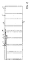
- pre-processed tubular foil 52 is used in which spaced apart transverse seals 53a, 53b, .... have already been made.
- the transverse seals extend from the second longitudinal edge 57 up to a distance from the first longitudinal edge 56, as shown in figure 5 .
- the device itself does not need to comprise means for making transverse seals, so that the device can be designed compact and economical.
- the transverse seals bound the cushion filled with a medium.
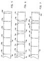
- An advantageous alternative pre-processed tubular foil 62 comprises repetitive series of a number and spaced apart transverse seals 63a, 63b, 63c and 63d ...
- the transverse seals here extend from the second longitudinal edge 67 up to a distance from the first longitudinal edge 66.
- the series is completed by a triplet of a transverse seal 68, a transverse row of perforations 64a, and a transverse seal 69, made after the last transverse seal 63d of the number of transverse seals.
- the transverse seals 68, 69 also extend here from the second longitudinal edge 67 up to a distance from the first longitudinal edge 66.
- the row of transverse perforation 64a extend up to both longitudinal edges.
- a pre-processed tubular foil 72 can be used in which spaced apart pairs of transverse seals 73a, 73b; 73c, 73d... have been made.
- the transverse seals extend here from the second longitudinal edge 77 up to a distance from the first longitudinal edge 76.
- a transverse row 74a, 74b, .... of perforations has been made between the transverse seals 73a, 73b, .... of each pair, as shown in figure 7 .
- the device itself does not need to comprise means for making transverse seals, and no means for making transverse rows of perforations, so that the device can be designed compact and economical.
- the transverse seals bound the cushion filled with a medium, and the transverse rows of perforations can be used for separating adjacent cushions from each other.
- the device according to the invention can further be provided with means for making a transverse seal in the pre-processed foil, and/or be provided with perforation means for making a transverse row of perforations, when another kind of pre-processed foil is taken as starting point.
- the device according to the invention works as follow. First the beginning of the pre-processed foil is manually fed into the device. A first cut is made manually, or a cut is made by the cutting means, which cut is used for inserting the tube into the pre-processed tubular foil. Subsequently the device can operate in a mechanized manner, the medium each time being introduced via the tube, after which the longitudinal seal is made by the sealing means in order to enclose the introduced medium.
- the tube also ensures a positioning and a guidance of the pre-processed tubular foil.
- FIG 3 a cross-section of a cushion is schematically shown.
- the cushion 15 filled with a medium has a second closed off longitudinal edge 18, and a first cut-through longitudinal edge 19 formed by two ends 16, 17 situated opposite it, and a longitudinal seal 20 situated between the first 19 and the second 18 longitudinal edge.
- the medium is situated here between the second longitudinal edge 18 and the longitudinal seal 20.
- each cushion 41a, 41b, ... has a second closed off longitudinal edge 42, and a first cut-through longitudinal edge 43 formed by two ends 44, 45 situated opposite it, and a longitudinal seal 46 situated between the first 43 and the second 42 longitudinal edge.
- the portion between the longitudinal seal 46 and the first longitudinal edge could be provided with prints for advertising or other (product) information, respectively.
- the sealing means can be adjusted such that the portion between the longitudinal seal and the first longitudinal edge is cut from the rest of the pre-processed foil during sealing.
- Adjacent cushions 41 a, 41 b, ... of a series 40 of cushions can be separated one from the other by one or more transverse seals 48a, ..., and/or be separated one from the other by a row of transverse perforations 49a, etc
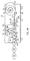
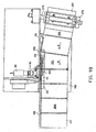
- the embodiment 100 of a device for manufacturing air or gas-filled cushions according to the invention is shown in figures 8A and further.
- the device 100 comprises a frame 300 onto which a shaft 101/173 has been mounted for support of a roll 102 of tubular foil 200.
- the tubular foil corresponds to the one of figure 6 , as can be seen in detail 9D, having transverse seals 162, 163 and in between them perforation 164.
- the tubular foil 200 will be pulled from the roll 102 in the direction 5, in order to turn it into gas-filled bags 201, 202.
- the shaft 101 comprises a rod 173, which at both ends is provided with cones 171, 172.
- the cone 172 can be removed in order to place a new roll 102.
- the rod 173 is bearing mounted in bearing block 170.
- the end of the bar shaft 173 extending outside the bearing block 170 is covered with a silicon strip, on which a stationary element that is not shown engages to slow the bar axis 173 down, so that the portion of the tubular foil 200 extending between the roller 102 and the sealing portion, cannot slacken.
- FIG 8B the location of a prox-sensor 140 and a counting wheel 141 is indicated.
- a tube 109 extends along the first longitudinal edge 106 of the tubular foil 200, which tube is buckled, having a portion 152 extending parallel to the longitudinal seam 161 yet to be made, and a portion 1 51 situated ahead of it, which is at an angle ⁇ of 4 to 5° to it.
- the shaft 173 is perpendicular to the tube portion 151.
- the tube portion 151 has a rounded off front edge in order to facilitate movement past it of the first longitudinal edge 106.
- the second portion 152 has an air discharge opening 110 facing the second longitudinal edge 107. Air is supplied to the tube 109 via a connection tube 182 and air pump 183.
- a blade 108 is situated, which is stationary, and serves to cut open the first longitudinal edge 106. Adjacent to the blade 108, on the other side of the air supply tube 109, the engagement by the sealing means that will be discussed below, starts.
- the sealing station is placed immediately adjacent to the air supply tube 109. Sealing takes place with the help of a sealing wire 139, clearly to be seen in the figures 8A and 8B , as well as figure 10 , which is suspended in seal unit 138, which with the help of compression springs 132 is suspended from attachment block 133, that is fixed with the frame 300. At the lower side a contra block 135 is situated, which is also fixed with the frame 300. Between sealing wire 139 and the tubular foil 200 a teflon tape 111 is situated, which runs about runners 130, 130a, the latter being biassed to the outside by means of a compression spring 134 to keep the teflon tape 111 tensioned. As can be seen in figure 10 a protective hood 190 shields the sealing area towards the cushions.
- a teflon tape 112 runs about runners 131 and 131 a, in which runner 131 a is biassed to the outside again by means of compression spring 134 to keep the teflon tape 112 tensioned.
- the teflon tape 112 runs on the contra block 135 supported by a strip of soft material, for instance a foam material 137 to level the pressure.
- the foil material is thus situated between two teflon tapes 111, 112 which run along with the tubular foil.
- a perfectly closed longitudinal seal 161 is realised in a continuous manner.
- the longitudinal seal 161 is realised in the area immediately following the blade 108, so that in fact a sealing at the first longitudinal edge 106 is kept intact, in which however the air supply tube 109 extends through it, substantially in longitudinal direction.
- drive rollers 103 and 104 are positioned underneath and above the tubular foil 200, which drive rollers are driven by motor reduction gear unit 118, via coupling 184, toothed wheel pair 185, and driving blocks 187, 188, in between which a compression spring 186 has been placed.
- Driving block 188 is fixed with the frame 300 and driving block 187 is clamped against block 188 for letting the wheels 103, 104 exert a clamping force on the foil.
- the driving blocks 187, 188 drive the drive wheels 103, 104. In turn these wheels drive the tubular foil 200.
- the drive wheels 103, 104 considered in width direction, only engage a little part of the tubular foil 200, just next to the air supply tube 109.
Abstract
Description
- Device for manufacturing cushions filled with a medium.
- The present invention relates to a device according to the precharacterizing portion of
claim 1. The medium may be a gaseous medium, but also another medium such as for instance a liquid or a powder. -
International patent application WO94/07678 - It is amongst others an object of the present invention to provide a device for manufacturing a cushion filled with a medium, with which the tubular foil can be positioned in the device and filled with the medium in a simple manner, which device has a very compact construction, and comprises few parts.
- To that end the present invention provides a device according to
claim 1. As a result the introduction means for the medium is also used as means for positioning the pre-processed tubular foil in the device. Moreover, merely one introduction means and one sealing means are necessary for sealing the cut in longitudinal direction, as a result of which the device can be designed compact and economical. - In a preferred embodiment of a device according to the invention the pre-processed tubular foil is provided with spaced apart transverse seals, each transverse seal extending from the second longitudinal edge up to a distance from the first longitudinal edge. Thus the device does not need to comprise transverse sealing means for making a transverse seal, and can be designed very compact and economical.
- Preferably the introduction means are formed by a tube having at least one opening, for instance a slit or holes, for introducing the medium into the pre-processed tubular foil, which opening preferably faces away from the first longitudinal edge. As a result the air is blown in from the first longitudinal edge towards the second longitudinal edge.
- Preferably the tube is positioned for extending in upstream direction, past the first longitudinal edge within the tubular foil. When discharging the air or gas the first longitudinal edge is pulled against the tube.
- The device according to the invention comprises means for pulling the first longitudinal edge taut, so that folds or creases in the tubular foil at the location of the sealing means are prevented and as a result leaks in the bags are prevented.
- Pulling taut takes place in a very simple manner when the means for pulling the first longitudinal edge taut are adapted for setting the tubular foil at an obtuse angle in the area immediately upstream of the sealing means. The first longitudinal edge is situated at the outside of the angle, and has to traverse a longer track than the second longitudinal edge. The second longitudinal edge will form creases, which promotes the filling process.
- The means for pulling the first longitudinal edge taut also comprise a supply roll or holder shaft for it that is positioned oblique with respect to the transport direction of the tubular foil and at the location of the sealing means, so that the tube of foil is supplied in an already oblique position.
- In an advantageous manner the tube can be a part of the means for pulling the first longitudinal edge taut and said tube comprises two portions that are at an obtuse angle to each other. The tube thus forms a guidance for the first longitudinal edge in the "outer curve", in which the tubular foil remains positioned against the tube during setting because of the air that comes out of the tube opening(s).
- The obtuse angle preferably is approximately 175 degrees, and can be realised by curving the tube and may then be gradual, though in view of ease of manufacturing a buckle shape may be used.
- The introduction of air into the tubular foil is improved when the tube, in a downstream portion of the obtuse angle, is provided with the discharge opening(s), so that the introduction of air is improved.
- The cutting means can be positioned at the location of the upstream end of the sealing means.
- Alternatively the cutting means can be positioned at a distance downstream of the upstream end of the sealing means.
- In a further preferred embodiment of a device according to the invention the pre-processed tubular foil is provided with repetitive series of a number of consecutive and spaced apart transverse seals, in which each transverse seal extends from the second longitudinal edge up to a distance from the first longitudinal edge, in which at a distance from a last transverse seal of the series a triplet is situated of consecutively and spaced apart from each other a transverse seal, a row of perforations, which row extends from the first to the second longitudinal edge, and a transverse seal, the distance between a transverse seal and the row of perforations of the triplet being smaller than the distance between the neighbouring transverse seals of the number of transverse seals. Thus the device does need not to comprise transverse sealing means for making a transverse seal and perforation means for making a row of perforations, along which the cushions can be separated, and can be designed very compact and economical.
- Using a pre-processed tubular foil makes it possible that a device according to the present invention does not need to comprise transverse sealing means and no means for making a row of perforations, and thus can be designed economical and with few parts.
- Further embodiments and advantages of a device for manufacturing cushions filled with a medium according to the invention will clearly appear from the description given below of some exemplary embodiments of the invention, which should be considered as illustrations only and not as limiting. In the drawings:
-
Figure 1 schematically shows a view of a device not according toclaim 1; -
Figure 2 schematically shows a view transverse to the view offigure 1 of a device not according toclaim 1; -
Figure 3 schematically shows a cross-section of the cushion obtainable by the device shown infigs.1 ,2 ; -
Figure 4 shows a perspective view of a series of cushions obtainable by the device shown infigs. 1 ,2 ; -
Figure 5 schematically shows an example of a pre-processed tubular foil to be supplied to a device shown infigs. 1 ,2 ; -
Figure 6 schematically shows an example of an alternative pre-processed tubular foil to be supplied to a device shown infigs 1 ,2 ; -
Figure 7 schematically shows an example of a further alternative pre-processed tubular foil to be supplied to a device shown infigs 1 ,2 ; -
Figures 8A and8B , respectively, show a view on a preferred embodiment of a device according to the invention and schematically show the build-up of a part thereof; -
Figure 9A and9B show schematic top views on the device of thefigures 8A and8B , in which some parts at the location of the sealing station have been left out for the sake of clarity. -
Figure 10 shows a view according to arrow X infigure 9A ; and -
Figure 11 shows a view according to arrow XI infigure 9B . - The present invention will be described below on the basis of air as medium. However, it will be clear that also cushions or bags can be filled with another gaseous medium such as nitrogen, oxygen, helium or the like, or with a non-gaseous medium such as a liquid or a powder.
- In
figures 1 and2 an exemplary embodiment of a device for manufacturing air-filled cushions is schematically shown in side view and top view, respectively, or vice-versa. The device preferably is provided with acarrier 1 for carrying a roll of pre-processedtubular foil 2. - The device is provided with two drive rollers 3, 4 between which the pre-processed
tubular foil 2 can be passed. The two drive rollers 3, 4 preferably are springmounted with respect to each other, and press against each other to such an extent that they hold the pre-processedtubular foil 2. By rotation of the drive rollers 3, 4 the pre-processedtubular foil 2 is pulled from thecarrier 1, so that the pre-processedtubular foil 2 is transported in asupply direction 5 through the device. To that end the drive rollers 3, 4 are provided at their surfaces with a material of a sufficiently high friction coefficient in a known manner. It will be clear that the invention is not limited to this way of passing the pre-processed tubular foil through the device, but that other passage devices can also be used. - The flexible pre-processed
tubular foil 2 is supplied to the device in flat condition. The pre-processedtubular foil 2 thus has a firstlongitudinal edge 6 and a second longitudinal edge 7 opposite each other. - The device is further provided with a cutting means 8 for making a cut in the pre-processed tubular foil 2 (
figure 2 ) only and at least near the firstlongitudinal edge 6 of the pre-processedtubular foil 2. - The device is also provided with an introduction means 9 for introducing air, or another medium, into the pre-processed
tubular foil 2. The introduction means 9 is elongated. Preferably the introduction means 9 is formed by a tube having aslit 10 for introducing the medium into the pre-processedtubular foil 2. In a manner known per se, thetube 9 is connected to a supply of medium, for instance a ventilating fan or the like. Alternatively a number of medium introduction openings placed adjacent to each other can be provided. Instead of a slit, holes or other kinds of openings can be used as well. - The
tube 9 can be inserted in thepre-processed foil 2; or through the cut made by the cutting means 8. In this way does thetube 9 not only ensure the introduction of a medium in the pre-processedtubular foil 2, but also the positioning of the pre-processedtubular foil 2 in the device. - Although at first sight it seems illogical to take a pre-processed tubular foil as starting point which is cut in longitudinal direction, in order to form two ends at one longitudinal edge, and not to use a centrefold foil which already has such a shape and is cheaper than pre-processed tubular foil, a cheaper final product is nonetheless obtained because the introduction means 9 is also used as positioning means for the pre-processed
tubular foil 2 in the device. Furthermore only one sealing means is necessary for sealing the cut made, in longitudinal direction. As a result the device becomes cheaper, and thus the final product. - Sealing means 11, 12 (
figure 1 ) are present for sealing the pre-processedtubular foil 2 in longitudinal direction and between thetube 9 and the second longitudinal edge 7. For instance the sealing means are formed by a circumferentialheated teflon band 11, and a pressing means 12 situated opposite it. Of course other sealing means for making the longitudinal seal can also be used. Making a seal in a synthetic foil generally takes place by means of sealing with the help of heat. - Preferably pre-processed
tubular foil 52 is used in which spaced aparttransverse seals longitudinal edge 57 up to a distance from the firstlongitudinal edge 56, as shown infigure 5 . By using such apre-processed foil 52 the device itself does not need to comprise means for making transverse seals, so that the device can be designed compact and economical. As will be clear the transverse seals bound the cushion filled with a medium. - An advantageous alternative pre-processed
tubular foil 62 comprises repetitive series of a number and spaced aparttransverse seals longitudinal edge 67 up to a distance from the firstlongitudinal edge 66. The series is completed by a triplet of atransverse seal 68, a transverse row ofperforations 64a, and atransverse seal 69, made after the lasttransverse seal 63d of the number of transverse seals. Thetransverse seals longitudinal edge 67 up to a distance from the firstlongitudinal edge 66. The row oftransverse perforation 64a extend up to both longitudinal edges. In this way it is possible in a simple manner to manufacture a number of air cushions, in the example given five, but any other number can also be used, which air cushions can easily be separated from a neighbouring series of five cushions, or another number, by the row of perforations. Moreover no means for making the transverse seals or transverse rows of perforations are necessary. - Alternatively a pre-processed
tubular foil 72 can be used in which spaced apart pairs oftransverse seals longitudinal edge 77 up to a distance from the firstlongitudinal edge 76. Atransverse row 74a, 74b, .... of perforations has been made between thetransverse seals figure 7 . By using such a pre-processedtubular foil 72 the device itself does not need to comprise means for making transverse seals, and no means for making transverse rows of perforations, so that the device can be designed compact and economical. As will be clear the transverse seals bound the cushion filled with a medium, and the transverse rows of perforations can be used for separating adjacent cushions from each other. - Alternatively the device according to the invention can further be provided with means for making a transverse seal in the pre-processed foil, and/or be provided with perforation means for making a transverse row of perforations, when another kind of pre-processed foil is taken as starting point.
- The device according to the invention works as follow. First the beginning of the pre-processed foil is manually fed into the device. A first cut is made manually, or a cut is made by the cutting means, which cut is used for inserting the tube into the pre-processed tubular foil. Subsequently the device can operate in a mechanized manner, the medium each time being introduced via the tube, after which the longitudinal seal is made by the sealing means in order to enclose the introduced medium. Here the tube also ensures a positioning and a guidance of the pre-processed tubular foil.
- In
figure 3 a cross-section of a cushion is schematically shown. Thecushion 15 filled with a medium has a second closed offlongitudinal edge 18, and a first cut-throughlongitudinal edge 19 formed by twoends 16, 17 situated opposite it, and alongitudinal seal 20 situated between the first 19 and the second 18 longitudinal edge. The medium is situated here between the secondlongitudinal edge 18 and thelongitudinal seal 20. - In
figure 4 a series 40 ofcushions cushion longitudinal edge 42, and a first cut-throughlongitudinal edge 43 formed by twoends longitudinal seal 46 situated between the first 43 and the second 42 longitudinal edge. Possibly the portion between thelongitudinal seal 46 and the first longitudinal edge could be provided with prints for advertising or other (product) information, respectively. Alternatively the sealing means can be adjusted such that the portion between the longitudinal seal and the first longitudinal edge is cut from the rest of the pre-processed foil during sealing. -
Adjacent cushions transverse seals 48a, ..., and/or be separated one from the other by a row oftransverse perforations 49a,..... - The
embodiment 100 of a device for manufacturing air or gas-filled cushions according to the invention is shown infigures 8A and further. Thedevice 100 comprises a frame 300 onto which ashaft 101/173 has been mounted for support of aroll 102 oftubular foil 200. The tubular foil corresponds to the one offigure 6 , as can be seen indetail 9D, havingtransverse seals perforation 164. In operation thetubular foil 200 will be pulled from theroll 102 in thedirection 5, in order to turn it into gas-filledbags - As can be seen in the
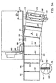
figures 9A and9B theshaft 101 comprises arod 173, which at both ends is provided withcones cone 172 can be removed in order to place anew roll 102. Therod 173 is bearing mounted in bearingblock 170. The end of thebar shaft 173 extending outside thebearing block 170 is covered with a silicon strip, on which a stationary element that is not shown engages to slow thebar axis 173 down, so that the portion of thetubular foil 200 extending between theroller 102 and the sealing portion, cannot slacken. - In
figure 8B the location of a prox-sensor 140 and acounting wheel 141 is indicated. - For the filling with air a
tube 109 extends along the firstlongitudinal edge 106 of thetubular foil 200, which tube is buckled, having aportion 152 extending parallel to thelongitudinal seam 161 yet to be made, and aportion 1 51 situated ahead of it, which is at an angle α of 4 to 5° to it. As can be seen in thefigures 9A and9B theshaft 173 is perpendicular to thetube portion 151. - The
tube portion 151 has a rounded off front edge in order to facilitate movement past it of the firstlongitudinal edge 106. Thesecond portion 152 has anair discharge opening 110 facing the secondlongitudinal edge 107. Air is supplied to thetube 109 via aconnection tube 182 andair pump 183. - Shortly downstream of the air supply opening 110 a
blade 108 is situated, which is stationary, and serves to cut open the firstlongitudinal edge 106. Adjacent to theblade 108, on the other side of theair supply tube 109, the engagement by the sealing means that will be discussed below, starts. - Considered in transverse direction, the sealing station is placed immediately adjacent to the
air supply tube 109. Sealing takes place with the help of asealing wire 139, clearly to be seen in thefigures 8A and8B , as well asfigure 10 , which is suspended inseal unit 138, which with the help of compression springs 132 is suspended fromattachment block 133, that is fixed with the frame 300. At the lower side acontra block 135 is situated, which is also fixed with the frame 300. Between sealingwire 139 and the tubular foil 200 ateflon tape 111 is situated, which runs aboutrunners compression spring 134 to keep theteflon tape 111 tensioned. As can be seen infigure 10 aprotective hood 190 shields the sealing area towards the cushions. - In a similar way a
teflon tape 112 runs aboutrunners runner 131 a is biassed to the outside again by means ofcompression spring 134 to keep theteflon tape 112 tensioned. Theteflon tape 112 runs on thecontra block 135 supported by a strip of soft material, for instance afoam material 137 to level the pressure. - The foil material is thus situated between two
teflon tapes longitudinal seal 161 is realised in a continuous manner. Thelongitudinal seal 161 is realised in the area immediately following theblade 108, so that in fact a sealing at the firstlongitudinal edge 106 is kept intact, in which however theair supply tube 109 extends through it, substantially in longitudinal direction. - Immediately downstream of the sealing
station drive rollers tubular foil 200, which drive rollers are driven by motor reduction gear unit 118, viacoupling 184, toothed wheel pair 185, and drivingblocks compression spring 186 has been placed. Drivingblock 188 is fixed with the frame 300 and drivingblock 187 is clamped againstblock 188 for letting thewheels drive wheels tubular foil 200. Infigures 9A and11 it can be seen that thedrive wheels tubular foil 200, just next to theair supply tube 109. - During transport of the
tubular foil 200 and during discharge of the air/gas from theopening 110 the firstlongitudinal edge 106 will be pulled taut about theportions tube 109. More towards the otherlongitudinal edge 107 there will be a material surplus, as a result of which pleats 165 (seefigure 9A ) will arise. As a result it is achieved that not only the filling of thecushions longitudinal seal 161 is realised. As can be seencushion 201 is still filled, while thelongitudinal seal 161 for said cushion is still being made. When theseal 161 is ready, thecushion 201 is filled completely. Thecushions 202 are horizontally supported bysupport plane 180. The ventilatingfan 150 cools off thelongitudinal seal 161.
Claims (13)
- Device for manufacturing cushions filled with a medium from synthetic tubular foil (2, 200), to which device flexible tubular foil (2, 200) is supplied in a supply direction (5), in which the flexible tubular foil is supplied in flat condition, in which the tubular foil has a first (6, 106) and a second (7, 107) longitudinal edge opposite each other, said device being provided with introduction means (9, 109) for introducing a medium, characterized in that said device is arranged for processing pre-processed tubular foil and has cutting means (8, 108) for making a cut in the pre-processed tubular foil only and at least near the first longitudinal edge (6, 106) of the foil, the introduction means (9, 109) being elongated and insertable in the pre-processed tubular foil through the cut made by the cutting means (8, 108) for abutment of the introduction means (9, 109) against the part of the first longitudinal edge (6, 106) that is not yet cut, and with sealing means (11, 12, 111, 112) for sealing the preprocessed tubular foil in longitudinal direction and between the introduction means (9, 109) and the second longitudinal edge (7, 107) for sealing off the cut made by the cutting means (8, 108);
wherein the device further comprises means (1, 101, 173, 151, 152) for pulling the first longitudinal edge (6, 106) taut which are adapted for setting the tubular foil at an obtuse angle in the area immediately upstream of the sealing means and which comprise a supply roll or holder shaft (1, 101, 173) for it that is positioned oblique with respect to the transport direction (5) of the tubular foil (2, 200) at the location of the sealing means (11, 12, 111, 112). - Device according to claim 1, in which the introduction means (9, 109) is formed by a tube having an opening for instance a slit (10) or holes (110), for introducing the medium into the pre-processed tubular foil, which opening preferably faces away from the first longitudinal edge (6, 106).
- Device according to claim 2, in which a tube (9, 109) is positioned for extending in upstream direction, past the first longitudinal edge (6, 106) within the tubular foil.
- Device according to claim 3, in which the tube (9, 109) is part of the means for pulling the first longitudinal edge (6, 106) taut and comprises two portions (151, 152) that are at an obtuse angle to each other.
- Device according to claim 4, in which the obtuse angle is approximately 175 degrees.
- Device according to claim 4 or 5, in which the obtuse angle in the tube (9, 109) is buckle-shaped.
- Device according to claim 1, 4 or 5, in which the tube (9, 109) in a downstream portion of the obtuse angle is provided with the discharge opening(s) (10, 110).
- Device according to claim 3 or 7, in Which the cutting means (8, 108) is positioned immediately downstream of the discharge opening(s) (10, 110).
- Device according to any one of the preceding claims, in which the cutting means (8, 108) is positioned at the location of the upstream end of the sealing means (11, 12 111, 112).
- Device according to any one of the claims 1-8, in which the cutting means (8, 108) is positioned at a distance downstream of the upstream end of the sealing means (11, 12, 111, 112).
- Device according to any one of the preceding claims, in which the pre-processed tubular foil (2, 200) is provided with spaced apart transverse seals (53a, 53b, 63a, 63b, 73a, 73b), each transverse seal extending from the second longitudinal edge (7, 107) up to a distance from the first longitudinal edge (6, 106).
- Device according to any one of the preceding claims, in which the pre-processed tubular foil (2, 200) is provided with repetitive series of a number of consecutive and spaced apart transverse seals (53a, 53b, 63a, 63b, 73a, 73b), in which each transverse seal extends from the second longitudinal edge (7, 107) up to a distance from the first longitudinal edge (6, 106), in which at a distance from a last transverse seal of the series a triplet is situated of consecutively and spaced apart from each other a transverse seal (68, 73a), a row of perforations (64a, 74a), which row extends from the first to the second longitudinal edge, and a transverse seal (69, 73b), the distance between a transverse seal and the row of perforations of the triplet being smaller than the distance between the neighbouring transverse seals of the number of transverse seals.
- Device according any one of the preceding claims 1, 2, 3 or 11, in which furthermore perforation means are provided for arranging a row of perforations (64a, 74a), which row extends transverse to the supply direction (5).
Applications Claiming Priority (3)
| Application Number | Priority Date | Filing Date | Title |
|---|---|---|---|
| NL1015127 | 2000-05-08 | ||
| NL1015127 | 2000-05-08 | ||
| PCT/NL2001/000351 WO2001085434A2 (en) | 2000-05-08 | 2001-05-08 | Device for manufacturing cushions filled with a medium, series of cushions and cushion manufactured by such a device and tubular foil |
Publications (3)
| Publication Number | Publication Date |
|---|---|
| EP1280651A2 EP1280651A2 (en) | 2003-02-05 |
| EP1280651B1 EP1280651B1 (en) | 2006-04-12 |
| EP1280651B2 true EP1280651B2 (en) | 2010-02-24 |
Family
ID=19771334
Family Applications (1)
| Application Number | Title | Priority Date | Filing Date |
|---|---|---|---|
| EP01932394A Expired - Lifetime EP1280651B2 (en) | 2000-05-08 | 2001-05-08 | Device for manufacturing cushions filled with a medium |
Country Status (5)
| Country | Link |
|---|---|
| EP (1) | EP1280651B2 (en) |
| AT (1) | ATE322969T1 (en) |
| AU (1) | AU5892101A (en) |
| DE (1) | DE60118724T3 (en) |
| WO (1) | WO2001085434A2 (en) |
Families Citing this family (33)
| Publication number | Priority date | Publication date | Assignee | Title |
|---|---|---|---|---|
| US7536837B2 (en) | 1999-03-09 | 2009-05-26 | Free-Flow Packaging International, Inc. | Apparatus for inflating and sealing pillows in packaging cushions |
| US8627637B2 (en) | 1999-09-22 | 2014-01-14 | Pregis Innovative Packaging, Inc. | Method and machine for the manufacture of air pillows |
| CA2384976A1 (en) | 1999-09-22 | 2001-03-29 | Ambassador Packaging Limited | Method and machine for the manufacture of air pillows |
| ATE508949T1 (en) | 2000-01-20 | 2011-05-15 | Free Flow Packaging Int Inc | APPARATUS FOR PRODUCING PNEUMATICALLY FILLED PACKAGING PILLOWS |
| US6410119B1 (en) | 2000-11-21 | 2002-06-25 | Free-Flow Packaging International, Inc. | Inflatable, cushioning, bubble wrap product having multiple, interconnected, bubble structures |
| US6651406B2 (en) * | 2001-02-13 | 2003-11-25 | Sealed Air Corporation (Us) | Apparatus and method for forming inflated containers |
| US6598373B2 (en) | 2001-02-13 | 2003-07-29 | Sealed Air Corporation (Us) | Apparatus and method for forming inflated containers |
| US7220476B2 (en) * | 2001-05-10 | 2007-05-22 | Sealed Air Corporation (Us) | Apparatus and method for forming inflated chambers |
| DE10160408C2 (en) | 2001-12-10 | 2003-11-06 | Johannes Loersch | Gas filled packing |
| US7174696B2 (en) | 2002-03-01 | 2007-02-13 | Free-Flow Packaging International, Inc. | Machine and method for inflating and sealing air-filled packing cushions |
| NL1020273C2 (en) * | 2002-03-28 | 2003-09-30 | Ideepak Holding B V | Seal device. |
| US7571584B2 (en) | 2004-06-01 | 2009-08-11 | Automated Packaging Systems, Inc. | Web and method for making fluid filled units |
| US7897219B2 (en) | 2004-06-01 | 2011-03-01 | Automated Packaging Systems, Inc. | Web and method for making fluid filled units |
| ES2608877T3 (en) | 2004-06-01 | 2017-04-17 | Automated Packaging Systems, Inc | Band and procedure to perform fluid-filled units |
| US7040073B2 (en) | 2004-08-30 | 2006-05-09 | Free-Flow Packaging International | Machine for inflating and sealing air-filled cushioning materials |
| US8020358B2 (en) | 2004-11-02 | 2011-09-20 | Sealed Air Corporation (Us) | Apparatus and method for forming inflated containers |
| NL1028625C2 (en) | 2005-03-24 | 2006-09-27 | Ideepak Holding B V | Improved sealing device for sealing foil material together by means of heat. |
| US7225599B2 (en) | 2005-04-05 | 2007-06-05 | Sealed Air Corporation | Apparatus and method for forming inflated articles |
| NL1028784C2 (en) * | 2005-04-15 | 2006-10-17 | Acl Systems B V | Device for producing gas-filled filler bags. |
| US7862870B2 (en) | 2005-05-06 | 2011-01-04 | Pregis Innovative Packaging, Inc. | Films for inflatable cushions |
| EP2084066B1 (en) | 2006-09-20 | 2013-05-29 | Pregis Innovative Packaging Inc. | Inflation and sealing device for inflatable air cushions |
| CN101883722A (en) | 2007-10-12 | 2010-11-10 | 普里吉斯创新包装公司 | Inflation and sealing device with disengagement mechanism |
| EP2209614B1 (en) | 2007-10-31 | 2015-08-19 | Automated Packaging Systems, Inc. | Web and method for making fluid filled units |
| US9205622B2 (en) | 2009-02-27 | 2015-12-08 | Automated Packaging Systems, Inc. | Web and method for making fluid filled units |
| GB2472388A (en) * | 2009-08-03 | 2011-02-09 | Tung-Lung Chiang | Air cushion maker |
| NL2003907C2 (en) | 2009-12-04 | 2011-06-07 | Ideepak Holding B V | Blow unit for an apparatus for making air-filled bags, apparatus comprising such a blow unit, system comprising such an apparatus and a method for making air-filled bags. |
| EP2521648B1 (en) | 2010-01-06 | 2019-02-27 | Pregis Innovative Packaging LLC | Packaging pillow device with upstream components |
| AU2012278849B2 (en) | 2011-07-07 | 2016-12-22 | Automated Packaging Systems, Inc. | Air cushion inflation machine |
| MX2015011259A (en) | 2013-03-15 | 2016-02-03 | Automated Packaging Syst Inc | On-demand inflatable packaging. |
| CA2931243A1 (en) * | 2013-11-21 | 2015-05-28 | Automated Packaging Systems, Inc. | Air cushion inflation machine |
| NL2012357B1 (en) | 2014-03-04 | 2015-12-03 | Ideepak Holding Bv | Sealing unit, sealing apparatus, method for manufacturing air or gas filled bags, and air or gas filled bag. |
| US10940660B2 (en) | 2015-08-03 | 2021-03-09 | Storopack Hans Reichenecker Gmbh | Device and method for manufacturing gas filled cushions from preconfigured film material |
| BR112018070261B1 (en) | 2016-03-30 | 2024-01-02 | Pregis Innovative Packaging Llc | PROTECTIVE PACKAGING FORMING DEVICE |
Citations (6)
| Publication number | Priority date | Publication date | Assignee | Title |
|---|---|---|---|---|
| US3660189A (en) † | 1969-04-28 | 1972-05-02 | Constantine T Troy | Closed cell structure and methods and apparatus for its manufacture |
| US3868285A (en) † | 1973-07-18 | 1975-02-25 | Constantine T Troy | Methods and apparatus for the manufacture of cellular cushioning materials |
| US4017351A (en) † | 1975-12-24 | 1977-04-12 | Minnesota Mining And Manufacturing Company | System and device for inflating and sealing air inflated cushioning material |
| US4021283A (en) † | 1974-01-24 | 1977-05-03 | Weikert Roy J | Method of making aseptic packaging |
| WO2001053153A1 (en) † | 2000-01-20 | 2001-07-26 | Free-Flow Packaging International, Inc. | System, method and material for making pneumatically filled packing cushions |
| WO2002014156A1 (en) † | 2000-08-14 | 2002-02-21 | Free-Flow Packaging International, Inc. | Methods and apparatus for inflating and sealing pillows in packaging |
Family Cites Families (1)
| Publication number | Priority date | Publication date | Assignee | Title |
|---|---|---|---|---|
| NL9201713A (en) * | 1992-10-02 | 1994-05-02 | Henk Schram | Device for manufacturing a cushion filled with gaseous medium. |
-
2001
- 2001-05-08 AT AT01932394T patent/ATE322969T1/en not_active IP Right Cessation
- 2001-05-08 EP EP01932394A patent/EP1280651B2/en not_active Expired - Lifetime
- 2001-05-08 AU AU58921/01A patent/AU5892101A/en not_active Abandoned
- 2001-05-08 DE DE2001618724 patent/DE60118724T3/en not_active Expired - Lifetime
- 2001-05-08 WO PCT/NL2001/000351 patent/WO2001085434A2/en active IP Right Grant
Patent Citations (6)
| Publication number | Priority date | Publication date | Assignee | Title |
|---|---|---|---|---|
| US3660189A (en) † | 1969-04-28 | 1972-05-02 | Constantine T Troy | Closed cell structure and methods and apparatus for its manufacture |
| US3868285A (en) † | 1973-07-18 | 1975-02-25 | Constantine T Troy | Methods and apparatus for the manufacture of cellular cushioning materials |
| US4021283A (en) † | 1974-01-24 | 1977-05-03 | Weikert Roy J | Method of making aseptic packaging |
| US4017351A (en) † | 1975-12-24 | 1977-04-12 | Minnesota Mining And Manufacturing Company | System and device for inflating and sealing air inflated cushioning material |
| WO2001053153A1 (en) † | 2000-01-20 | 2001-07-26 | Free-Flow Packaging International, Inc. | System, method and material for making pneumatically filled packing cushions |
| WO2002014156A1 (en) † | 2000-08-14 | 2002-02-21 | Free-Flow Packaging International, Inc. | Methods and apparatus for inflating and sealing pillows in packaging |
Also Published As
| Publication number | Publication date |
|---|---|
| EP1280651B1 (en) | 2006-04-12 |
| DE60118724T3 (en) | 2010-07-01 |
| DE60118724D1 (en) | 2006-05-24 |
| WO2001085434A8 (en) | 2004-05-13 |
| EP1280651A2 (en) | 2003-02-05 |
| DE60118724T2 (en) | 2007-05-10 |
| ATE322969T1 (en) | 2006-04-15 |
| WO2001085434A2 (en) | 2001-11-15 |
| AU5892101A (en) | 2001-11-20 |
| WO2001085434A3 (en) | 2002-08-15 |
Similar Documents
| Publication | Publication Date | Title |
|---|---|---|
| EP1280651B2 (en) | Device for manufacturing cushions filled with a medium | |
| US10913561B2 (en) | Replaceable blade | |
| US5873215A (en) | Machine and method for manufacturing pneumatically filled packing cushions | |
| US4858416A (en) | Tensionless seal apparatus and method | |
| JP4504462B1 (en) | Air shock absorber manufacturing equipment | |
| US20150158604A1 (en) | Machine and methods for the manufacture of air-filled cushions | |
| EP2230067B2 (en) | Machine and method for producing rolls of pre-cut bags with die-cut handles | |
| EP0449551A1 (en) | Method of and apparatus for forming, filling and sealing packages | |
| US20140261871A1 (en) | Nozzle With Side and Tip Outlet | |
| JPH0451403B2 (en) | ||
| JP2006264697A (en) | Packaging bag manufacturing apparatus | |
| US6375785B1 (en) | Device for manufacturing cushions filled with a gaseous medium | |
| EP2141007B1 (en) | Inflation and sealing device with rotary cutter | |
| GB2384459A (en) | Manufacture of air cushions from tubing with a gas injector continuously within the tubing | |
| CN109153213B (en) | Inflatable cushion type inflation and sealing device | |
| JP2706713B2 (en) | Air cushion production equipment for packing | |
| EP1022124A1 (en) | Device for manufacturing cushions filled with a gaseous medium | |
| EP0174386B1 (en) | Apparatus for folding web-shaped member | |
| US7067025B2 (en) | Machine for the production of air pillows used for packaging by means of a tubular film disposed on a reel | |
| EP1932765A2 (en) | Device and method for packaging in a modified atmosphere | |
| JP2002255105A (en) | Filling and packaging machine | |
| JPH0319148B2 (en) | ||
| JPH0741693B2 (en) | Bag making equipment | |
| JPH0646939U (en) | Bag making equipment |
Legal Events
| Date | Code | Title | Description |
|---|---|---|---|
| PUAI | Public reference made under article 153(3) epc to a published international application that has entered the european phase |
Free format text: ORIGINAL CODE: 0009012 |
|
| 17P | Request for examination filed |
Effective date: 20020204 |
|
| AK | Designated contracting states |
Designated state(s): AT BE CH CY DE DK ES FI FR GB GR IE IT LI LU MC NL PT SE TR |
|
| AX | Request for extension of the european patent |
Extension state: AL LT LV MK RO SI |
|
| RAP1 | Party data changed (applicant data changed or rights of an application transferred) |
Owner name: FREE-FLOW PACKAGING INTERNATIONAL, INC. Owner name: IDEEPAK B.V. |
|
| RIC1 | Information provided on ipc code assigned before grant |
Ipc: 7B 29C 49/00 A Ipc: 7B 31D 5/00 B Ipc: 7B 65D 81/05 B |
|
| 17Q | First examination report despatched |
Effective date: 20041126 |
|
| GRAP | Despatch of communication of intention to grant a patent |
Free format text: ORIGINAL CODE: EPIDOSNIGR1 |
|
| RAP1 | Party data changed (applicant data changed or rights of an application transferred) |
Owner name: FREE-FLOW PACKAGING INTERNATIONAL, INC. Owner name: CASE PACKING SALES EUROPE B.V. Owner name: IDEEPAK B.V. |
|
| RTI1 | Title (correction) |
Free format text: DEVICE FOR MANUFACTURING CUSHIONS FILLED WITH A MEDIUM |
|
| GRAS | Grant fee paid |
Free format text: ORIGINAL CODE: EPIDOSNIGR3 |
|
| GRAA | (expected) grant |
Free format text: ORIGINAL CODE: 0009210 |
|
| AK | Designated contracting states |
Kind code of ref document: B1 Designated state(s): AT BE CH CY DE DK ES FI FR GB GR IE IT LI LU MC NL PT SE TR |
|
| PG25 | Lapsed in a contracting state [announced via postgrant information from national office to epo] |
Ref country code: LI Free format text: LAPSE BECAUSE OF FAILURE TO SUBMIT A TRANSLATION OF THE DESCRIPTION OR TO PAY THE FEE WITHIN THE PRESCRIBED TIME-LIMIT Effective date: 20060412 Ref country code: IT Free format text: LAPSE BECAUSE OF FAILURE TO SUBMIT A TRANSLATION OF THE DESCRIPTION OR TO PAY THE FEE WITHIN THE PRESCRIBED TIME-LIMIT;WARNING: LAPSES OF ITALIAN PATENTS WITH EFFECTIVE DATE BEFORE 2007 MAY HAVE OCCURRED AT ANY TIME BEFORE 2007. THE CORRECT EFFECTIVE DATE MAY BE DIFFERENT FROM THE ONE RECORDED. Effective date: 20060412 Ref country code: FI Free format text: LAPSE BECAUSE OF FAILURE TO SUBMIT A TRANSLATION OF THE DESCRIPTION OR TO PAY THE FEE WITHIN THE PRESCRIBED TIME-LIMIT Effective date: 20060412 Ref country code: CH Free format text: LAPSE BECAUSE OF FAILURE TO SUBMIT A TRANSLATION OF THE DESCRIPTION OR TO PAY THE FEE WITHIN THE PRESCRIBED TIME-LIMIT Effective date: 20060412 Ref country code: AT Free format text: LAPSE BECAUSE OF FAILURE TO SUBMIT A TRANSLATION OF THE DESCRIPTION OR TO PAY THE FEE WITHIN THE PRESCRIBED TIME-LIMIT Effective date: 20060412 Ref country code: BE Free format text: LAPSE BECAUSE OF FAILURE TO SUBMIT A TRANSLATION OF THE DESCRIPTION OR TO PAY THE FEE WITHIN THE PRESCRIBED TIME-LIMIT Effective date: 20060412 |
|
| REG | Reference to a national code |
Ref country code: GB Ref legal event code: FG4D |
|
| REG | Reference to a national code |
Ref country code: CH Ref legal event code: EP |
|
| PG25 | Lapsed in a contracting state [announced via postgrant information from national office to epo] |
Ref country code: IE Free format text: LAPSE BECAUSE OF NON-PAYMENT OF DUE FEES Effective date: 20060508 |
|
| REF | Corresponds to: |
Ref document number: 60118724 Country of ref document: DE Date of ref document: 20060524 Kind code of ref document: P |
|
| PG25 | Lapsed in a contracting state [announced via postgrant information from national office to epo] |
Ref country code: MC Free format text: LAPSE BECAUSE OF NON-PAYMENT OF DUE FEES Effective date: 20060531 |
|
| REG | Reference to a national code |
Ref country code: IE Ref legal event code: FG4D |
|
| PG25 | Lapsed in a contracting state [announced via postgrant information from national office to epo] |
Ref country code: SE Free format text: LAPSE BECAUSE OF FAILURE TO SUBMIT A TRANSLATION OF THE DESCRIPTION OR TO PAY THE FEE WITHIN THE PRESCRIBED TIME-LIMIT Effective date: 20060712 Ref country code: DK Free format text: LAPSE BECAUSE OF FAILURE TO SUBMIT A TRANSLATION OF THE DESCRIPTION OR TO PAY THE FEE WITHIN THE PRESCRIBED TIME-LIMIT Effective date: 20060712 |
|
| PG25 | Lapsed in a contracting state [announced via postgrant information from national office to epo] |
Ref country code: ES Free format text: LAPSE BECAUSE OF FAILURE TO SUBMIT A TRANSLATION OF THE DESCRIPTION OR TO PAY THE FEE WITHIN THE PRESCRIBED TIME-LIMIT Effective date: 20060723 |
|
| PG25 | Lapsed in a contracting state [announced via postgrant information from national office to epo] |
Ref country code: PT Free format text: LAPSE BECAUSE OF FAILURE TO SUBMIT A TRANSLATION OF THE DESCRIPTION OR TO PAY THE FEE WITHIN THE PRESCRIBED TIME-LIMIT Effective date: 20060912 |
|
| RAP2 | Party data changed (patent owner data changed or rights of a patent transferred) |
Owner name: FREE-FLOW PACKAGING INTERNATIONAL, INC. |
|
| REG | Reference to a national code |
Ref country code: CH Ref legal event code: PL |
|
| ET | Fr: translation filed | ||
| NLT2 | Nl: modifications (of names), taken from the european patent patent bulletin |
Owner name: FREE-FLOW PACKAGING INTERNATIONAL, INC. Effective date: 20060927 |
|
| NLS | Nl: assignments of ep-patents |
Owner name: FREE-FLOW PACKAGING INTERNATIONAL, INC. Effective date: 20061213 |
|
| REG | Reference to a national code |
Ref country code: GB Ref legal event code: 732E |
|
| PLBI | Opposition filed |
Free format text: ORIGINAL CODE: 0009260 |
|
| PLAX | Notice of opposition and request to file observation + time limit sent |
Free format text: ORIGINAL CODE: EPIDOSNOBS2 |
|
| 26 | Opposition filed |
Opponent name: PREGIS INNOVATIVE PACKAGING, INC. Effective date: 20070112 |
|
| NLR1 | Nl: opposition has been filed with the epo |
Opponent name: PREGIS INNOVATIVE PACKAGING, INC. |
|
| PLBB | Reply of patent proprietor to notice(s) of opposition received |
Free format text: ORIGINAL CODE: EPIDOSNOBS3 |
|
| REG | Reference to a national code |
Ref country code: FR Ref legal event code: TP |
|
| PG25 | Lapsed in a contracting state [announced via postgrant information from national office to epo] |
Ref country code: GR Free format text: LAPSE BECAUSE OF FAILURE TO SUBMIT A TRANSLATION OF THE DESCRIPTION OR TO PAY THE FEE WITHIN THE PRESCRIBED TIME-LIMIT Effective date: 20060713 |
|
| PG25 | Lapsed in a contracting state [announced via postgrant information from national office to epo] |
Ref country code: TR Free format text: LAPSE BECAUSE OF FAILURE TO SUBMIT A TRANSLATION OF THE DESCRIPTION OR TO PAY THE FEE WITHIN THE PRESCRIBED TIME-LIMIT Effective date: 20060412 Ref country code: LU Free format text: LAPSE BECAUSE OF NON-PAYMENT OF DUE FEES Effective date: 20060508 |
|
| PG25 | Lapsed in a contracting state [announced via postgrant information from national office to epo] |
Ref country code: CY Free format text: LAPSE BECAUSE OF FAILURE TO SUBMIT A TRANSLATION OF THE DESCRIPTION OR TO PAY THE FEE WITHIN THE PRESCRIBED TIME-LIMIT Effective date: 20060412 |
|
| PUAH | Patent maintained in amended form |
Free format text: ORIGINAL CODE: 0009272 |
|
| STAA | Information on the status of an ep patent application or granted ep patent |
Free format text: STATUS: PATENT MAINTAINED AS AMENDED |
|
| 27A | Patent maintained in amended form |
Effective date: 20100224 |
|
| AK | Designated contracting states |
Kind code of ref document: B2 Designated state(s): AT BE CH CY DE DK ES FI FR GB GR IE IT LI LU MC NL PT SE TR |
|
| REG | Reference to a national code |
Ref country code: ES Ref legal event code: FD2A Effective date: 20060509 |
|
| REG | Reference to a national code |
Ref country code: NL Ref legal event code: T3 |
|
| REG | Reference to a national code |
Ref country code: FR Ref legal event code: PLFP Year of fee payment: 16 |
|
| REG | Reference to a national code |
Ref country code: FR Ref legal event code: PLFP Year of fee payment: 17 |
|
| REG | Reference to a national code |
Ref country code: FR Ref legal event code: PLFP Year of fee payment: 18 |
|
| PGFP | Annual fee paid to national office [announced via postgrant information from national office to epo] |
Ref country code: DE Payment date: 20200428 Year of fee payment: 20 Ref country code: NL Payment date: 20200513 Year of fee payment: 20 Ref country code: FR Payment date: 20200414 Year of fee payment: 20 |
|
| PGFP | Annual fee paid to national office [announced via postgrant information from national office to epo] |
Ref country code: GB Payment date: 20200430 Year of fee payment: 20 |
|
| REG | Reference to a national code |
Ref country code: DE Ref legal event code: R071 Ref document number: 60118724 Country of ref document: DE |
|
| REG | Reference to a national code |
Ref country code: GB Ref legal event code: PE20 Expiry date: 20210507 |
|
| REG | Reference to a national code |
Ref country code: NL Ref legal event code: MK Effective date: 20210507 |
|
| PG25 | Lapsed in a contracting state [announced via postgrant information from national office to epo] |
Ref country code: GB Free format text: LAPSE BECAUSE OF EXPIRATION OF PROTECTION Effective date: 20210507 |