EP1281426A1 - Cartridge filter with anti-rotation feature - Google Patents
Cartridge filter with anti-rotation feature Download PDFInfo
- Publication number
- EP1281426A1 EP1281426A1 EP02017138A EP02017138A EP1281426A1 EP 1281426 A1 EP1281426 A1 EP 1281426A1 EP 02017138 A EP02017138 A EP 02017138A EP 02017138 A EP02017138 A EP 02017138A EP 1281426 A1 EP1281426 A1 EP 1281426A1
- Authority
- EP
- European Patent Office
- Prior art keywords
- filter
- casing
- center tube
- bowl
- assembly
- Prior art date
- Legal status (The legal status is an assumption and is not a legal conclusion. Google has not performed a legal analysis and makes no representation as to the accuracy of the status listed.)
- Withdrawn
Links
- 230000002093 peripheral effect Effects 0.000 claims description 8
- 230000013011 mating Effects 0.000 claims 2
- 230000005540 biological transmission Effects 0.000 abstract description 2
- 239000000446 fuel Substances 0.000 description 19
- 239000007788 liquid Substances 0.000 description 14
- 239000000356 contaminant Substances 0.000 description 10
- 239000002245 particle Substances 0.000 description 6
- 238000007789 sealing Methods 0.000 description 5
- 238000004519 manufacturing process Methods 0.000 description 3
- 238000000926 separation method Methods 0.000 description 3
- 238000002485 combustion reaction Methods 0.000 description 2
- 239000002283 diesel fuel Substances 0.000 description 2
- 238000001914 filtration Methods 0.000 description 2
- 239000012530 fluid Substances 0.000 description 2
- 239000000463 material Substances 0.000 description 2
- 229920002449 FKM Polymers 0.000 description 1
- 229920002292 Nylon 6 Polymers 0.000 description 1
- 239000004952 Polyamide Substances 0.000 description 1
- 230000000712 assembly Effects 0.000 description 1
- 238000000429 assembly Methods 0.000 description 1
- 229920002678 cellulose Polymers 0.000 description 1
- 239000001913 cellulose Substances 0.000 description 1
- 238000007796 conventional method Methods 0.000 description 1
- 238000013461 design Methods 0.000 description 1
- 238000004512 die casting Methods 0.000 description 1
- 230000000694 effects Effects 0.000 description 1
- 230000007613 environmental effect Effects 0.000 description 1
- 239000002184 metal Substances 0.000 description 1
- 238000000034 method Methods 0.000 description 1
- 238000012544 monitoring process Methods 0.000 description 1
- 239000013618 particulate matter Substances 0.000 description 1
- ISWSIDIOOBJBQZ-UHFFFAOYSA-N phenol group Chemical group C1(=CC=CC=C1)O ISWSIDIOOBJBQZ-UHFFFAOYSA-N 0.000 description 1
- 239000004033 plastic Substances 0.000 description 1
- 238000009428 plumbing Methods 0.000 description 1
- 229920002647 polyamide Polymers 0.000 description 1
- 229920000728 polyester Polymers 0.000 description 1
- 230000000087 stabilizing effect Effects 0.000 description 1
- 238000012546 transfer Methods 0.000 description 1
- XLYOFNOQVPJJNP-UHFFFAOYSA-N water Substances O XLYOFNOQVPJJNP-UHFFFAOYSA-N 0.000 description 1
Images


Classifications
-
- B—PERFORMING OPERATIONS; TRANSPORTING
- B01—PHYSICAL OR CHEMICAL PROCESSES OR APPARATUS IN GENERAL
- B01D—SEPARATION
- B01D36/00—Filter circuits or combinations of filters with other separating devices
- B01D36/003—Filters in combination with devices for the removal of liquids
-
- B—PERFORMING OPERATIONS; TRANSPORTING
- B01—PHYSICAL OR CHEMICAL PROCESSES OR APPARATUS IN GENERAL
- B01D—SEPARATION
- B01D29/00—Filters with filtering elements stationary during filtration, e.g. pressure or suction filters, not covered by groups B01D24/00 - B01D27/00; Filtering elements therefor
- B01D29/11—Filters with filtering elements stationary during filtration, e.g. pressure or suction filters, not covered by groups B01D24/00 - B01D27/00; Filtering elements therefor with bag, cage, hose, tube, sleeve or like filtering elements
- B01D29/13—Supported filter elements
- B01D29/15—Supported filter elements arranged for inward flow filtration
- B01D29/21—Supported filter elements arranged for inward flow filtration with corrugated, folded or wound sheets
-
- B—PERFORMING OPERATIONS; TRANSPORTING
- B01—PHYSICAL OR CHEMICAL PROCESSES OR APPARATUS IN GENERAL
- B01D—SEPARATION
- B01D29/00—Filters with filtering elements stationary during filtration, e.g. pressure or suction filters, not covered by groups B01D24/00 - B01D27/00; Filtering elements therefor
- B01D29/96—Filters with filtering elements stationary during filtration, e.g. pressure or suction filters, not covered by groups B01D24/00 - B01D27/00; Filtering elements therefor in which the filtering elements are moved between filtering operations; Particular measures for removing or replacing the filtering elements; Transport systems for filters
-
- B—PERFORMING OPERATIONS; TRANSPORTING
- B01—PHYSICAL OR CHEMICAL PROCESSES OR APPARATUS IN GENERAL
- B01D—SEPARATION
- B01D2201/00—Details relating to filtering apparatus
- B01D2201/04—Supports for the filtering elements
- B01D2201/0415—Details of supporting structures
-
- B—PERFORMING OPERATIONS; TRANSPORTING
- B01—PHYSICAL OR CHEMICAL PROCESSES OR APPARATUS IN GENERAL
- B01D—SEPARATION
- B01D2201/00—Details relating to filtering apparatus
- B01D2201/29—Filter cartridge constructions
- B01D2201/291—End caps
-
- B—PERFORMING OPERATIONS; TRANSPORTING
- B01—PHYSICAL OR CHEMICAL PROCESSES OR APPARATUS IN GENERAL
- B01D—SEPARATION
- B01D2201/00—Details relating to filtering apparatus
- B01D2201/30—Filter housing constructions
- B01D2201/301—Details of removable closures, lids, caps, filter heads
- B01D2201/302—Details of removable closures, lids, caps, filter heads having inlet or outlet ports
-
- B—PERFORMING OPERATIONS; TRANSPORTING
- B01—PHYSICAL OR CHEMICAL PROCESSES OR APPARATUS IN GENERAL
- B01D—SEPARATION
- B01D2201/00—Details relating to filtering apparatus
- B01D2201/40—Special measures for connecting different parts of the filter
- B01D2201/4046—Means for avoiding false mounting of different parts
-
- B—PERFORMING OPERATIONS; TRANSPORTING
- B01—PHYSICAL OR CHEMICAL PROCESSES OR APPARATUS IN GENERAL
- B01D—SEPARATION
- B01D2201/00—Details relating to filtering apparatus
- B01D2201/40—Special measures for connecting different parts of the filter
- B01D2201/4076—Anti-rotational means
-
- B—PERFORMING OPERATIONS; TRANSPORTING
- B01—PHYSICAL OR CHEMICAL PROCESSES OR APPARATUS IN GENERAL
- B01D—SEPARATION
- B01D2201/00—Details relating to filtering apparatus
- B01D2201/40—Special measures for connecting different parts of the filter
- B01D2201/4084—Snap or Seeger ring connecting means
-
- Y—GENERAL TAGGING OF NEW TECHNOLOGICAL DEVELOPMENTS; GENERAL TAGGING OF CROSS-SECTIONAL TECHNOLOGIES SPANNING OVER SEVERAL SECTIONS OF THE IPC; TECHNICAL SUBJECTS COVERED BY FORMER USPC CROSS-REFERENCE ART COLLECTIONS [XRACs] AND DIGESTS
- Y10—TECHNICAL SUBJECTS COVERED BY FORMER USPC
- Y10S—TECHNICAL SUBJECTS COVERED BY FORMER USPC CROSS-REFERENCE ART COLLECTIONS [XRACs] AND DIGESTS
- Y10S210/00—Liquid purification or separation
- Y10S210/17—Twist-on
Definitions
- the present invention relates generally to fluid filters, and more particularly to replaceable fuel filters and housing assemblies therefor.
- Filters which separate out particulate matter from liquids, as well as liquid contaminants, are well-known in the industry. Such filters are particularly useful for diesel fuel, where water is removed from the diesel fuel passing through the filter to increase the combustion efficiency of the engine. Such fuel filters are also useful with gasoline, oil and other liquid fuels.
- a number of such filters include cup-shaped collection bowls located below the filter media to collect the liquid contaminants, whereby a collection bowl with a threaded upper end is removably connected to the housing or casing of a filter cartridge.
- the filter cartridge includes a ring of appropriate filtration media bounded by upper and lower end caps. Particles in the fuel flowing through the filter media are separated out in the media, while the liquid contaminants collect on the surface of the media, and drop down into the attached collection bowl.
- the collection bowl is transparent to allow monitoring of the liquid level and includes a drain to allow removal of the liquid contaminants when appropriate.
- One technique for attaching the collection bowl to the cartridge is to include a ring-shaped member supported by a radially in-turned portion of the cartridge casing, where the ring-shaped member includes an annular portion with radially-outward directed threads.
- the collection bowl, with radially inward directed threads, is then easily screwed onto or off of the filter member.
- Radial flow passages in the ring-shaped member fluidly connect a peripheral cavity in the casing, that is, between the casing and the outer surface of the filter media, with the attached collection bowl, such that liquid contaminants can pass radially-inward through the passages and then downwardly into the attached collection bowl.
- Another known filter has a similar structure, whereby the ring-shaped member has radially-inward directed threads, and the collection bowl has radially-outward directed threads.
- the casing of the filter cartridge is designed to be spun onto a filter head, and includes an upper tap plate with a series of peripheral openings fluidly connected with the peripheral cavity, and a central opening fluidly connected with the central cavity of the element. The openings direct fluid into and out of the filter.
- the above filters have received widespread acceptance in the marketplace as providing reliable, efficient devices for separating particles and liquid contaminants from fuel.
- one of the limitations of some of the above filters is that the filter cartridge cannot be removed from the casing of the filter. This requires the entire filter cartridge and casing to be disposed of when the media is spent, which can raise environmental issues.
- the collection bowl is typically the only re-usable component as it can be screwed onto and off of the cartridge when the cartridge is replaced.
- the present invention provides a novel and unique filter, where a filter cartridge must be present within the casing of the filter in order that the collection bowl can be attached and the filter used in a fuel system.
- the filter cartridge must also have a special anti-rotation feature in order that the collection bowl can be screwed onto the cartridge. This allows control over the type of filter cartridge used within the filter and prevents the use of the filter without a cartridge.
- the filter is simple and cost-effective to manufacture and assemble, and provides efficient separation of particles and liquid contaminants from fuel passing through the cartridge.
- the filter includes a casing enclosing a removable filter cartridge.
- the filter cartridge includes a ring of filter media circumscribing a central cavity and having upper and lower ends.
- the invention incorporates a filter center tube into the housing or bowl.
- the center tube is permanently fixed to the bowl but allowed to rotate within a pocket in the bottom of the bowl.
- the top of the center tube is threaded for fastening to a stud on the filter mounting head.
- the top has a sealing collar disposed outside of the bowl including a sealing ring that is drawn into the filter mounting head when the center tube is threaded onto the stud.
- the center tube cannot be threaded onto the stud without the filter assembled over the center tube and into the bowl.
- the operator In order to assemble the bowl to the head, the operator must turn the outside of the bowl. If a filter is not present, the bowl will turn independently of the center tube and no torque is transmitted to the threads.
- a series of tabs or features spaced around the inner perimeter of the wall of the bowl interlock with corresponding grooves or features in the outside diameter of the end cap of the filter.
- Tabs or features on the outer diameter of the center tube also interlock with grooves or features in the inside diameter of the end cap.
- the interlocking arrangement on the outside diameter and inside diameter of the end cap forms a lock that then allows torque transmission from the bowl, through the end cap, to the center tube. This arrangement permits the threads to engage and the bowl assembly to be installed.
- the present invention provides a novel and unique filter, which includes a filter casing with a removable filter cartridge, and a removable collection bowl.
- the filter requires a filter cartridge to be present the filter in order that the collection bowl can be attached and the filter used, and provides control over the type of filter cartridge located in the filter.
- the filter is simple and cost-effective to manufacture and assemble, and provides efficient separation of particles and liquid contaminants from fuel in the fuel system.
- the filter 10 includes a filter head or manifold 12, a bowl assembly 14, a slip center tube 16, and a removable filter cartridge 18.
- the filter head 12 includes inlet passages 20 (from e.g., the tank) and outlet passages 22 (to e.g., a transfer pump and then to the fuel injectors) for directing fuel into and out of the filter.
- the inlet and outlet passages are used depending upon the plumbing of the system. Unused passages are typically plugged.
- the inlet passages provide fuel to be filtered to the peripheral region of the casing, while outlet passages draw filtered fuel from the central region of the casing.
- a primping pump (not shown) is provided in the inlet passages 20 to push fuel through the filter after an element change.
- a temperature sensor, vacuum switch and pressure sensor can be mounted in the inlet, outlet and/or return passages for appropriate control and sensing of the fuel flowing through the filter head.
- filter head 12 further includes a cylindrical sealing collar 32 extending axially downward whereby an outside diameter seal 33 is interposed between the upper rim of the bowl assembly 14 and the sealing collar 32.
- Inside diameter radial seals 6, 8 are provided at each end of the filter 18 to maintain a proper flow through the filter assembly (see FIG. 1).
- attachment of the center tube 16 to the bowl assembly 14 is accomplished by a one-time snap fit interlock 16a into a high stiffness pocket 14a formed in the bowl assembly 14.
- the pocket 14a is slotted to permit the drainage of liquid; however, the drain itself is omitted for clarity.
- the center tube 16 is permitted to rotate within the pocket 14a. In other words, the center tube 16 rotates relative to the bowl assembly 14 but it cannot be removed from the pocket 14a due to the snap-fit interlock 16a.
- a separate clutch arrangement locks the center tube 16 to the bowl assembly 14.
- the invention should not be limited to the snap-fit interlock illustrated in the accompanying drawings; instead, the invention may comprises a center pin or other attachment mechanism that permits the center tube 16 to rotate within the housing or bowl assembly 14.
- the center tube 16 includes a series of radially-inward directed threads 34, and the filter head 12 includes a series of cooperating radially-outward directed threads 35 (see FIG. 1) which enable the filter head 12 to be screwed onto and off of the bowl assembly 14 via the center tube 16 as described below.
- the bowl assembly 14 cannot be assembled to the filter head 12 unless the filter 18 is properly disposed in the bowl assembly 14. If assembly is attempted without a filter 18 (or with an improper filter), the center tube 16 will rotate in the pocket 14a and thus it will not transmit torque to the threads 34, 35.
- the filter head 12 is preferably formed from an appropriate material suitable for the particular application, for example metal, and is formed using conventional techniques, such as die-casting.
- Casing and collection bowl assembly 14 is also preferably formed of a material which is appropriate for the particular application, for example, a hard opaque plastic.
- the filter 18 is formed of Nylon 6/6 end caps, Viton inside diameter sealing gaskets, polyamide pleat stabilizing wrap and a phenolic coated, cellulose and 10 micron polyester blended filter media.
- the center tube 16 is provided with modified splines 17 along an outer diameter above the pocket 14a.
- the bowl assembly 14 is provided with a series of locking tabs 15 on the inside of the outermost wall of the bowl assembly 14.
- the filter 18 is provided with interior and exterior locking tabs/slots 19a, 19b on the filter end cap.
- the internally-projecting locking tabs 19a are designed and formed to mate with the externally-facing splines 17 provided on the center tube 16, and the externally-facing locking slots 19b are designed and formed to mate with the tabs 15 formed on the inside of the of the wall of the bowl assembly 14.
- the exact location of the two-part locking assembly (e.g. locking tabs 19a, 19b) of the filter 18 may be varied without departing from the spirit and scope of this invention.
- the exact location, number and arrangement of the tabs 15 and splines 17 are design to interact with locking elements 19, 19b to provide a locking clutch assembly between the bowl assembly 14, filter 18 and center tube 16.
- the fuel enters one of inlet passages and is directed into the peripheral cavity outside the filter 18, and flows radially inward through filter media where particles in the fuel are separated.
- the filtered fuel than flows out through one of the outlet passages. Liquid contaminants are collected on the outer surface of the filter media, and pass downwardly and inwardly through openings into the attached collection bowl assembly 14.
- the present invention provides a novel and unique filter having a removable cartridge in a casing, and a removable collection bowl, which requires a specific filter cartridge to be installed within the filter, and which cannot be used if the filter cartridge is absent.
- the preferred embodiment shown in the accompanying drawings is a cylindrical housing and filter member; however, the specific shape of the components of this invention should not be limited to the arrangements shown and described herein.
- the bowl assembly 14, center tube 16 and filter 18 may be formed in any suitable shape to achieve the purposes of this invention.
Landscapes
- Chemical & Material Sciences (AREA)
- Chemical Kinetics & Catalysis (AREA)
- Filtration Of Liquid (AREA)
Abstract
Description
- The present invention relates generally to fluid filters, and more particularly to replaceable fuel filters and housing assemblies therefor.
- Filters which separate out particulate matter from liquids, as well as liquid contaminants, are well-known in the industry. Such filters are particularly useful for diesel fuel, where water is removed from the diesel fuel passing through the filter to increase the combustion efficiency of the engine. Such fuel filters are also useful with gasoline, oil and other liquid fuels.
- A number of such filters include cup-shaped collection bowls located below the filter media to collect the liquid contaminants, whereby a collection bowl with a threaded upper end is removably connected to the housing or casing of a filter cartridge. The filter cartridge includes a ring of appropriate filtration media bounded by upper and lower end caps. Particles in the fuel flowing through the filter media are separated out in the media, while the liquid contaminants collect on the surface of the media, and drop down into the attached collection bowl. The collection bowl is transparent to allow monitoring of the liquid level and includes a drain to allow removal of the liquid contaminants when appropriate.
- One technique for attaching the collection bowl to the cartridge is to include a ring-shaped member supported by a radially in-turned portion of the cartridge casing, where the ring-shaped member includes an annular portion with radially-outward directed threads. The collection bowl, with radially inward directed threads, is then easily screwed onto or off of the filter member. Radial flow passages in the ring-shaped member fluidly connect a peripheral cavity in the casing, that is, between the casing and the outer surface of the filter media, with the attached collection bowl, such that liquid contaminants can pass radially-inward through the passages and then downwardly into the attached collection bowl.
- Another known filter has a similar structure, whereby the ring-shaped member has radially-inward directed threads, and the collection bowl has radially-outward directed threads.
- In some instances, the casing of the filter cartridge is designed to be spun onto a filter head, and includes an upper tap plate with a series of peripheral openings fluidly connected with the peripheral cavity, and a central opening fluidly connected with the central cavity of the element. The openings direct fluid into and out of the filter.
- The above filters have received widespread acceptance in the marketplace as providing reliable, efficient devices for separating particles and liquid contaminants from fuel. Unfortunately, one of the limitations of some of the above filters is that the filter cartridge cannot be removed from the casing of the filter. This requires the entire filter cartridge and casing to be disposed of when the media is spent, which can raise environmental issues. The collection bowl is typically the only re-usable component as it can be screwed onto and off of the cartridge when the cartridge is replaced.
- On the other hand, providing a filter where the cartridge can be easily removed from the casing also raises issues. For example, it is possible that an end user or repair person can forget to install or re-install a fresh cartridge, and thereby operate the engine without proper filtration. It can also be confusing as to the correct type of filter cartridge used in the filter, and a user or repair person may attempt to install an incorrect cartridge in the casing. This can all have a serious effect on the operation of the internal combustion engine.
- Thus, it is believed there is a demand in the industry for a filter including a filter cartridge and attached collection bowl, whereby the filter cartridge is removable from the filter casing but where the filter cannot be assembled or used without a proper filter cartridge installed.
- It is also believed there is a continual demand for new and unique filters with removable collection bowls which are easy and cost-effective to manufacture and assembly and provide efficient separation of particles and liquid contaminants in fuel flowing through the filter.
- The present invention provides a novel and unique filter, where a filter cartridge must be present within the casing of the filter in order that the collection bowl can be attached and the filter used in a fuel system. The filter cartridge must also have a special anti-rotation feature in order that the collection bowl can be screwed onto the cartridge. This allows control over the type of filter cartridge used within the filter and prevents the use of the filter without a cartridge. The filter is simple and cost-effective to manufacture and assemble, and provides efficient separation of particles and liquid contaminants from fuel passing through the cartridge.
- According to the preferred embodiment of the present invention, the filter includes a casing enclosing a removable filter cartridge. The filter cartridge includes a ring of filter media circumscribing a central cavity and having upper and lower ends.
- The invention incorporates a filter center tube into the housing or bowl. The center tube is permanently fixed to the bowl but allowed to rotate within a pocket in the bottom of the bowl. The top of the center tube is threaded for fastening to a stud on the filter mounting head. The top has a sealing collar disposed outside of the bowl including a sealing ring that is drawn into the filter mounting head when the center tube is threaded onto the stud.
- With this invention, the center tube cannot be threaded onto the stud without the filter assembled over the center tube and into the bowl. In order to assemble the bowl to the head, the operator must turn the outside of the bowl. If a filter is not present, the bowl will turn independently of the center tube and no torque is transmitted to the threads.
- When the filter is properly installed, a series of tabs or features spaced around the inner perimeter of the wall of the bowl interlock with corresponding grooves or features in the outside diameter of the end cap of the filter. Tabs or features on the outer diameter of the center tube also interlock with grooves or features in the inside diameter of the end cap. The interlocking arrangement on the outside diameter and inside diameter of the end cap forms a lock that then allows torque transmission from the bowl, through the end cap, to the center tube. This arrangement permits the threads to engage and the bowl assembly to be installed.
- As such, the present invention provides a novel and unique filter, which includes a filter casing with a removable filter cartridge, and a removable collection bowl. The filter requires a filter cartridge to be present the filter in order that the collection bowl can be attached and the filter used, and provides control over the type of filter cartridge located in the filter. The filter is simple and cost-effective to manufacture and assemble, and provides efficient separation of particles and liquid contaminants from fuel in the fuel system.
- Further features and advantages of the present invention will become apparent to those skilled in the art upon reviewing the following specification and attached drawings.
-
- FIG. 1 is a cross-sectional side view of the filter assembly of this invention showing a filter cartridge in the filter;
- FIG. 2 is an enlarged, partially cross-sectioned view of an upper portion of the filter assembly of FIG. 1;
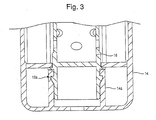
- FIG. 3 is an enlarged, partially cross-sectioned view of a lower portion of the filter assembly of FIG. 1;
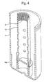
- FIG. 4 is a partial cross-section view of the bowl assembly and center tube of the filter assembly of FIG. 1;
- FIG. 5 is an enlarged, partially cross-sectioned view of the clutch assembly including the locking tabs of the filter assembly of the present invention;
- FIG. 6 is a perspective view of the filter;
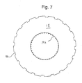
- FIG. 7 is a bottom view of the filter of FIG. 6 showing the interior and exterior locking tabs or splines.
-
- Referring to the drawings, and initially to FIG. 1, a filter constructed according to the principles of the present invention is indicated generally at 10. The
filter 10 includes a filter head ormanifold 12, abowl assembly 14, aslip center tube 16, and aremovable filter cartridge 18. - The
filter head 12 includes inlet passages 20 (from e.g., the tank) and outlet passages 22 (to e.g., a transfer pump and then to the fuel injectors) for directing fuel into and out of the filter. The inlet and outlet passages are used depending upon the plumbing of the system. Unused passages are typically plugged. The inlet passages provide fuel to be filtered to the peripheral region of the casing, while outlet passages draw filtered fuel from the central region of the casing. A primping pump (not shown) is provided in theinlet passages 20 to push fuel through the filter after an element change. A temperature sensor, vacuum switch and pressure sensor can be mounted in the inlet, outlet and/or return passages for appropriate control and sensing of the fuel flowing through the filter head. - Referring now to FIG. 2,
filter head 12 further includes acylindrical sealing collar 32 extending axially downward whereby anoutside diameter seal 33 is interposed between the upper rim of thebowl assembly 14 and the sealingcollar 32. Inside diameter radial seals 6, 8 are provided at each end of thefilter 18 to maintain a proper flow through the filter assembly (see FIG. 1). - With reference to FIG. 3, attachment of the
center tube 16 to thebowl assembly 14 is accomplished by a one-time snapfit interlock 16a into ahigh stiffness pocket 14a formed in thebowl assembly 14. Thepocket 14a is slotted to permit the drainage of liquid; however, the drain itself is omitted for clarity. Significantly, thecenter tube 16 is permitted to rotate within thepocket 14a. In other words, thecenter tube 16 rotates relative to thebowl assembly 14 but it cannot be removed from thepocket 14a due to the snap-fit interlock 16a. As will be described below, a separate clutch arrangement locks thecenter tube 16 to thebowl assembly 14. - It is noted that this invention should not be limited to the snap-fit interlock illustrated in the accompanying drawings; instead, the invention may comprises a center pin or other attachment mechanism that permits the
center tube 16 to rotate within the housing orbowl assembly 14. - Referring now to FIG. 4, the
center tube 16 includes a series of radially-inward directedthreads 34, and thefilter head 12 includes a series of cooperating radially-outward directed threads 35 (see FIG. 1) which enable thefilter head 12 to be screwed onto and off of thebowl assembly 14 via thecenter tube 16 as described below. In accordance with this invention, thebowl assembly 14 cannot be assembled to thefilter head 12 unless thefilter 18 is properly disposed in thebowl assembly 14. If assembly is attempted without a filter 18 (or with an improper filter), thecenter tube 16 will rotate in thepocket 14a and thus it will not transmit torque to thethreads - The
filter head 12 is preferably formed from an appropriate material suitable for the particular application, for example metal, and is formed using conventional techniques, such as die-casting. Casing andcollection bowl assembly 14 is also preferably formed of a material which is appropriate for the particular application, for example, a hard opaque plastic. Thefilter 18 is formed ofNylon 6/6 end caps, Viton inside diameter sealing gaskets, polyamide pleat stabilizing wrap and a phenolic coated, cellulose and 10 micron polyester blended filter media. - Referring now to FIG. 5 and 6, the clutch interlock arrangement, that locks the
center tube 16 relative to the bowl assembly, will now be described. Thecenter tube 16 is provided with modifiedsplines 17 along an outer diameter above thepocket 14a. Although the drawings show several splines 17, the exact number can be varied without departing from or changing the protection associated with this invention. In addition, thebowl assembly 14 is provided with a series of lockingtabs 15 on the inside of the outermost wall of thebowl assembly 14. With reference to Figures 6 and 7, thefilter 18 is provided with interior and exterior locking tabs/slots locking tabs 19a are designed and formed to mate with the externally-facingsplines 17 provided on thecenter tube 16, and the externally-facinglocking slots 19b are designed and formed to mate with thetabs 15 formed on the inside of the of the wall of thebowl assembly 14. Of course, the exact location of the two-part locking assembly (e.g. locking tabs filter 18 may be varied without departing from the spirit and scope of this invention. Likewise, the exact location, number and arrangement of thetabs 15 andsplines 17 are design to interact with lockingelements 19, 19b to provide a locking clutch assembly between thebowl assembly 14,filter 18 andcenter tube 16. - During operation of the filter, the fuel enters one of inlet passages and is directed into the peripheral cavity outside the
filter 18, and flows radially inward through filter media where particles in the fuel are separated. The filtered fuel than flows out through one of the outlet passages. Liquid contaminants are collected on the outer surface of the filter media, and pass downwardly and inwardly through openings into the attachedcollection bowl assembly 14. - Thus, as described above, the present invention provides a novel and unique filter having a removable cartridge in a casing, and a removable collection bowl, which requires a specific filter cartridge to be installed within the filter, and which cannot be used if the filter cartridge is absent.
- The principles, preferred embodiments and modes of operation of the present invention have been described in the foregoing specification. The invention which is intended to be protected herein should not, however, be construed as limited to the particular form described as it is to be regarded as illustrative rather than restrictive. Variations and changes may be made by those skilled in the art without departing from the scope and spirit of the invention as set forth in the appended claims.
- For example, the preferred embodiment shown in the accompanying drawings is a cylindrical housing and filter member; however, the specific shape of the components of this invention should not be limited to the arrangements shown and described herein. The
bowl assembly 14,center tube 16 andfilter 18 may be formed in any suitable shape to achieve the purposes of this invention.
Claims (15)
- A filter assembly comprising:a casing having an opening at one end thereof and defining a cavity, said casing including an anti-rotation device disposed on an inner peripheral surface thereof;a center tube rotatably supported within said cavity for relative rotation of said center tube with respect to said casing about a central axis, said tube has an anti-rotation device disposed on an outer peripheral surface thereof, said tube is threaded at one end thereof;a filter element removably disposed within said casing about said tube, said filter element including a first anti-rotation device cooperating with said anti-rotation device of said casing to rotationally fix said filter element with respect to said casing and a second anti-rotation device cooperating with said anti-rotation device of said tube to rotationally fix said filter element with respect to said tube;a mounting head secured to said one end of said casing for sealingly closing said opening therein, said mounting head is threadedly fastened to said one end of said tube.
- The filter assembly as defined in claim 1, wherein said first anti-rotation device and said anti-rotation device of said tube each include at least one radially outwardly projecting locking tab, and said second anti-rotation device and said anti-rotation device of said casing each include at least one radially inwardly projecting locking tab.
- The filter assembly as defined in claim 1, wherein said locking tabs are circumferentially spaced-apart from one other around the central axis.
- The filter assembly as defined in claim 1, further comprising a seal interface between said casing and said mounting head.
- The filter assembly as defined in claim 1, wherein said center tube comprises flow apertures passing therethrough.
- The filter assembly as defined in claim 1, wherein said center tube comprises threads for mating with corresponding threads provided on said mounting head.
- The filter assembly as defined in claim 1, wherein said center tube matingly engages said casing while permitting said relative rotation.
- A filter assembly as defined in claim 1, wherein said center tube, said filter, and said bowl assembly are fixed against relative rotation when said filter is properly positioned within said casing.
- The filter assembly as in claim 8, further including a collection bowl with threads removably connected to the ring-shaped member.
- The filter assembly as in claim 1, wherein said casing is cylindrical.
- A filter cartridge removably positionable within a casing, the filter cartridge comprising:wherein at least one of said upper and lower end caps comprise internally and externally oriented key members for engaging anti-rotational elements disposed on two relatively rotatable elements.a filter media circumscribing a central cavity and having upper and lower ends,an upper end cap bonded to the upper end of the filter media, anda lower end cap bonded to the lower end of the filter media,
- The filter cartridge of claim 11, wherein said two relatively rotatable elements comprise a center tube member and a bowl assembly, whereby said key members are adapted to mate with both the center tube and the bowl assembly.
- The filter cartridge as in claim 11, wherein said keys are circumferentially spaced-apart from each other around said central cavity, and project both radially outward and radially inwardly therefrom.
- The filter cartridge as in claim 11, wherein said filter media and said lower end cap are unitary with each other.
- A filter subassembly, comprising:a casing with first anti-rotation devices disposed circumferentially around an inner surface of the casing,a rotatable center tube attached to a lower end of the casing, said center tube provided with second anti-rotation devices disposed on an external circumferential surface, anda filter cartridge removably disposed within the casing, said filter cartridge including a filter media separating a central cavity from a peripheral cavity in the casing and having upper and lower ends, said filter cartridge further including third and forth anti-rotation devices projecting radially therefrom, said anti-rotation devices of said filter cartridge mating with the first and second anti-rotation devices on the casing and the center tube, respectively, to rotationally fix the center tube with respect to the casing.
Applications Claiming Priority (2)
| Application Number | Priority Date | Filing Date | Title |
|---|---|---|---|
| US09/917,721 US6679990B2 (en) | 2001-07-31 | 2001-07-31 | Cartridge filter with integrated threading having anti-rotation feature |
| US917721 | 2004-08-12 |
Publications (1)
| Publication Number | Publication Date |
|---|---|
| EP1281426A1 true EP1281426A1 (en) | 2003-02-05 |
Family
ID=25439233
Family Applications (1)
| Application Number | Title | Priority Date | Filing Date |
|---|---|---|---|
| EP02017138A Withdrawn EP1281426A1 (en) | 2001-07-31 | 2002-07-30 | Cartridge filter with anti-rotation feature |
Country Status (2)
| Country | Link |
|---|---|
| US (1) | US6679990B2 (en) |
| EP (1) | EP1281426A1 (en) |
Cited By (18)
| Publication number | Priority date | Publication date | Assignee | Title |
|---|---|---|---|---|
| EP1366789A1 (en) * | 2002-05-10 | 2003-12-03 | Hydraulik-Ring Gmbh | Filter cartridge (for liquids) which can be destroyed by freezing especially for fuel cell vehicles and combustion engines preferably diesel engines |
| WO2005005014A1 (en) * | 2003-07-01 | 2005-01-20 | Parker-Hannifin Corporation | Filter assembly with slip thread |
| EP1693097A1 (en) * | 2005-02-15 | 2006-08-23 | Mann+Hummel Gmbh | Filter system |
| EP1754525A1 (en) * | 2005-08-16 | 2007-02-21 | Donaldson Company, Inc. | Air cleaner having anti-rotational arrangement and methods |
| WO2007028425A1 (en) * | 2005-09-02 | 2007-03-15 | Joma-Polytec Kunststofftechnik Gmbh | Oil filter arrangement and filter element for an oil filter arrangement |
| WO2010003980A1 (en) * | 2008-07-10 | 2010-01-14 | Deere & Company | Filter arrangement for filtering a liquid or gaseous medium |
| WO2010102690A1 (en) | 2009-03-13 | 2010-09-16 | Hydac Filtertechnik Gmbh | Filter device, in particular return line suction filter, and filter element for use in such a filter device |
| EP2233190A1 (en) * | 2009-03-25 | 2010-09-29 | Mahle International GmbH | Liquid filter |
| US7918997B2 (en) | 2005-02-15 | 2011-04-05 | Mann+Hummel Gmbh | Filter system |
| US8074673B2 (en) | 2004-05-18 | 2011-12-13 | Hydraulik-Ring Gmbh | Freeze-resistant metering valve |
| US8201393B2 (en) | 2008-03-05 | 2012-06-19 | Hilite Germany Gmbh | Exhaust-gas aftertreatment device |
| US8266892B2 (en) | 2007-01-25 | 2012-09-18 | Friedrich Zapf | Calibrated dosing unit, especially of an exhaust gas treatment unit |
| WO2014023381A1 (en) * | 2012-08-07 | 2014-02-13 | Daimler Ag | Filter unit |
| US8875502B2 (en) | 2010-12-14 | 2014-11-04 | Cummins Ltd. | SCR exhaust gas aftertreatment device |
| US8938949B2 (en) | 2009-08-03 | 2015-01-27 | Cummins Ltd. | SCR exhaust gas aftertreatment device |
| WO2015177274A1 (en) * | 2014-05-21 | 2015-11-26 | C.C. Jensen A/S | Key system to ensure correct use of inserts |
| WO2018050237A1 (en) * | 2016-09-15 | 2018-03-22 | Mahle International Gmbh | Filter device, in particular air filter, for an air supply system of an internal combustion engine |
| CN107914517A (en) * | 2016-10-11 | 2018-04-17 | 美国轮轴制造公司 | The vehicle bridge component of release mechanism and spinning hydraulic filter with hydraulic operation |
Families Citing this family (40)
| Publication number | Priority date | Publication date | Assignee | Title |
|---|---|---|---|---|
| JP2004532101A (en) * | 2001-04-02 | 2004-10-21 | ドナルドソン カンパニー,インコーポレイティド | Filter and method in container cartridge with interlocking mechanism |
| US7168573B2 (en) * | 2002-06-07 | 2007-01-30 | Baldwin Filters, Inc. | Environmentally friendly filter cartridge |
| US20050178716A1 (en) * | 2002-10-08 | 2005-08-18 | Pti Technologies, Inc. | Filter assembly and filter element with integral seal |
| US6959819B2 (en) * | 2002-10-08 | 2005-11-01 | Pti Technologies, Inc. | Fatigue rated glass filled plastic filter assembly incorporating a coreless plastic filter element with integral seal |
| US20060226065A1 (en) * | 2003-12-15 | 2006-10-12 | Meddock Leroy J | Coaxial full-flow and bypass oil filter apparatus and method |
| US7704396B2 (en) * | 2003-12-15 | 2010-04-27 | Filtran Llc | Coaxial full-flow and bypass oil filter with spring/gasket arrangement |
| US7090773B2 (en) * | 2003-12-15 | 2006-08-15 | Spx Corporation | Coaxial full-flow and bypass oil filter |
| US7704397B2 (en) * | 2003-12-15 | 2010-04-27 | Filtran Llc | Coaxial full-flow and bypass oil filter having cap with blades |
| US7614504B2 (en) | 2004-02-16 | 2009-11-10 | Cummins Filtration Ip Inc. | Open-end flow entrance spin-on filter |
| US7434697B2 (en) * | 2004-02-16 | 2008-10-14 | Fleetguard Inc. | Disposable, spin-on filter |
| DE102004025811A1 (en) * | 2004-05-05 | 2006-03-23 | Mann + Hummel Gmbh | Filter element and liquid filter for freeze-endangered fluids and method for producing the filter element |
| US7377620B2 (en) * | 2005-05-26 | 2008-05-27 | Hewlett-Packard Development Company, L.P. | Hydrophobic nozzle exit with improved micro fluid ejection dynamics |
| US8293103B2 (en) * | 2005-12-08 | 2012-10-23 | Donaldson Company, Inc. | Spin-on filter assembly and methods |
| CA2584927C (en) * | 2006-04-13 | 2011-02-08 | Wix Filtration Corp. | A body for actuating a standpipe of a replaceable filter element |
| US7416663B2 (en) * | 2006-04-14 | 2008-08-26 | Pleatco Electronic & Filter Corporation | Replacement filter cartridge assembly having an internal lock ring |
| DE102006034482A1 (en) * | 2006-07-21 | 2008-01-24 | Joma-Polytec Kunststofftechnik Gmbh | Oil filter assembly and filter element for this |
| WO2008086304A1 (en) * | 2007-01-05 | 2008-07-17 | Honeywell International Inc. | Fluid filter cartridge assembly |
| EP2091626B1 (en) | 2007-04-27 | 2011-12-28 | Donaldson Company, Inc. | Liquid filter assembly, system, and methods |
| US20090184041A1 (en) * | 2008-01-23 | 2009-07-23 | Cummins Filtration Ip, Inc. | Fluid filter with clear shell portion |
| EP2767320B1 (en) | 2008-04-25 | 2019-02-20 | Donaldson Company, Inc. | Top load liquid filter assembly, system, and methods |
| US10010817B2 (en) | 2008-04-25 | 2018-07-03 | Donaldson Company, Inc. | Top load liquid filter assembly, system, and methods |
| JP5852962B2 (en) | 2009-11-05 | 2016-02-03 | ドナルドソン カンパニー,インコーポレイティド | Liquid filter assembly, system and method |
| US8794222B2 (en) * | 2010-01-27 | 2014-08-05 | Cummins Filtration Ip, Inc. | Crankcase ventilation inside-out flow rotating coalescer |
| US8940068B2 (en) | 2010-01-27 | 2015-01-27 | Cummins Filtration Ip Inc. | Magnetically driven rotating separator |
| US8974567B2 (en) | 2010-01-27 | 2015-03-10 | Cummins Filtration Ip Inc. | Rotating coalescer with keyed drive |
| US8893689B2 (en) | 2010-01-27 | 2014-11-25 | Cummins Filtration Ip, Inc. | Crankcase ventilation self-cleaning coalescer with intermittent rotation |
| US9194265B2 (en) | 2010-01-27 | 2015-11-24 | Cummins Filtration Ip, Inc. | Rotating separator with housing preventing separated liquid carryover |
| IT1398974B1 (en) * | 2010-03-24 | 2013-03-28 | Ufi Filters Spa | FILTER FOR INTERNAL COMBUSTION ENGINES. |
| ITRE20110028A1 (en) * | 2011-04-20 | 2012-10-21 | Ufi Innovation Ct Srl | FILTERING GROUP |
| US11235274B2 (en) | 2011-06-30 | 2022-02-01 | Donaldson Company, Inc. | Filter systems; components; features; and, methods of assembly and use |
| US10092868B2 (en) | 2011-08-31 | 2018-10-09 | Donaldson Company, Inc. | Liquid filter assembly, system and methods |
| BR112014009743A2 (en) | 2011-11-04 | 2017-05-02 | Cummins Filtration Ip Inc | rotary separator for separating fluid from fluid mix |
| US9352257B2 (en) | 2012-01-31 | 2016-05-31 | Donaldson Company, Inc. | Interlock device |
| US10005012B2 (en) | 2013-06-06 | 2018-06-26 | Donaldson Company, Inc. | Interlock device |
| WO2017083842A1 (en) | 2015-11-12 | 2017-05-18 | Unger Marketing International, Llc | Water conditioning systems |
| EP4272855A3 (en) * | 2016-02-12 | 2024-01-03 | Donaldson Company, Inc. | Filter elements and air cleaner assemblies |
| US10428704B2 (en) | 2017-04-26 | 2019-10-01 | Ford Global Technologies, Llc | Oil filter anti-rotation lock for an engine |
| US10315717B2 (en) | 2017-08-28 | 2019-06-11 | Matt Risley | Retractable bipod motorcycle stand |
| US11318399B2 (en) * | 2020-02-24 | 2022-05-03 | Caterpillar Inc. | Locking feature for a filter |
| CN115434909A (en) * | 2022-09-13 | 2022-12-06 | 江苏亚洋压缩机有限公司 | Screw air compressor machine of environmental protection |
Citations (3)
| Publication number | Priority date | Publication date | Assignee | Title |
|---|---|---|---|---|
| US4299699A (en) * | 1980-10-14 | 1981-11-10 | Boogay Marc A | Backwashable helical-media coalescer |
| DE9016239U1 (en) * | 1990-11-29 | 1991-02-14 | E. Begerow Gmbh & Co, 6536 Langenlonsheim, De | |
| BE1011567A3 (en) * | 1997-11-25 | 1999-11-09 | Atlas Copco Airpower Nv | Filter unit and filter element for this |
Family Cites Families (3)
| Publication number | Priority date | Publication date | Assignee | Title |
|---|---|---|---|---|
| US4626348A (en) | 1984-06-29 | 1986-12-02 | Parker-Hannifin Corporation | End cap which will accommodate flow reversal |
| US6139738A (en) | 1999-03-10 | 2000-10-31 | Parker-Hannifin Corporation | Cartridge filter with integrated threading having anti-rotation feature |
| US6481580B1 (en) * | 2000-08-23 | 2002-11-19 | Caterpillar Inc | Fluid filter with locking mechanism |
-
2001
- 2001-07-31 US US09/917,721 patent/US6679990B2/en not_active Expired - Lifetime
-
2002
- 2002-07-30 EP EP02017138A patent/EP1281426A1/en not_active Withdrawn
Patent Citations (3)
| Publication number | Priority date | Publication date | Assignee | Title |
|---|---|---|---|---|
| US4299699A (en) * | 1980-10-14 | 1981-11-10 | Boogay Marc A | Backwashable helical-media coalescer |
| DE9016239U1 (en) * | 1990-11-29 | 1991-02-14 | E. Begerow Gmbh & Co, 6536 Langenlonsheim, De | |
| BE1011567A3 (en) * | 1997-11-25 | 1999-11-09 | Atlas Copco Airpower Nv | Filter unit and filter element for this |
Cited By (36)
| Publication number | Priority date | Publication date | Assignee | Title |
|---|---|---|---|---|
| EP1366789A1 (en) * | 2002-05-10 | 2003-12-03 | Hydraulik-Ring Gmbh | Filter cartridge (for liquids) which can be destroyed by freezing especially for fuel cell vehicles and combustion engines preferably diesel engines |
| WO2005005014A1 (en) * | 2003-07-01 | 2005-01-20 | Parker-Hannifin Corporation | Filter assembly with slip thread |
| US8074673B2 (en) | 2004-05-18 | 2011-12-13 | Hydraulik-Ring Gmbh | Freeze-resistant metering valve |
| US7918997B2 (en) | 2005-02-15 | 2011-04-05 | Mann+Hummel Gmbh | Filter system |
| EP1693097A1 (en) * | 2005-02-15 | 2006-08-23 | Mann+Hummel Gmbh | Filter system |
| CN101272842B (en) * | 2005-08-16 | 2011-11-23 | 唐纳森公司 | Air cleaner having anti-rotational arragement and methods |
| US8444735B2 (en) | 2005-08-16 | 2013-05-21 | Donaldson Company, Inc. | Air cleaner having anti-rotational arrangement and methods |
| US8753415B2 (en) | 2005-08-16 | 2014-06-17 | Donaldson Company, Inc. | Air cleaner having anti-rotational arrangements and methods |
| EP2236192A1 (en) * | 2005-08-16 | 2010-10-06 | Donaldson Company, Inc. | Air cleaner having anti-rotational arrangement and methods |
| EP1754525A1 (en) * | 2005-08-16 | 2007-02-21 | Donaldson Company, Inc. | Air cleaner having anti-rotational arrangement and methods |
| WO2007022171A1 (en) * | 2005-08-16 | 2007-02-22 | Donaldson Company, Inc. | Air cleaner having anti-rotational arragement and methods |
| US8163056B2 (en) | 2005-08-16 | 2012-04-24 | Donaldson Company, Inc. | Air cleaner having anti-rotational arrangement and methods |
| WO2007028425A1 (en) * | 2005-09-02 | 2007-03-15 | Joma-Polytec Kunststofftechnik Gmbh | Oil filter arrangement and filter element for an oil filter arrangement |
| US8875491B2 (en) | 2007-01-25 | 2014-11-04 | Cummins Ltd. | Exhaust gas aftertreatment system and method |
| US8266892B2 (en) | 2007-01-25 | 2012-09-18 | Friedrich Zapf | Calibrated dosing unit, especially of an exhaust gas treatment unit |
| US8959895B2 (en) | 2008-03-05 | 2015-02-24 | Cummins Ltd. | Exhaust-gas aftertreatment device |
| US8201393B2 (en) | 2008-03-05 | 2012-06-19 | Hilite Germany Gmbh | Exhaust-gas aftertreatment device |
| CN102137703A (en) * | 2008-07-10 | 2011-07-27 | 迪尔公司 | Filter arrangement for filtering a liquid or gaseous medium |
| WO2010003980A1 (en) * | 2008-07-10 | 2010-01-14 | Deere & Company | Filter arrangement for filtering a liquid or gaseous medium |
| CN102137703B (en) * | 2008-07-10 | 2014-04-09 | 迪尔公司 | Filter arrangement for filtering liquid or gaseous medium |
| US8932463B2 (en) | 2008-07-10 | 2015-01-13 | Deere & Company | Filter assembly |
| US8840787B2 (en) | 2009-03-13 | 2014-09-23 | Hydac Filtertechnik Gmbh | Filter device, in particular return line suction filter, and filter element for use in such a filter device |
| WO2010102690A1 (en) | 2009-03-13 | 2010-09-16 | Hydac Filtertechnik Gmbh | Filter device, in particular return line suction filter, and filter element for use in such a filter device |
| EP2233190A1 (en) * | 2009-03-25 | 2010-09-29 | Mahle International GmbH | Liquid filter |
| US8938949B2 (en) | 2009-08-03 | 2015-01-27 | Cummins Ltd. | SCR exhaust gas aftertreatment device |
| US8875502B2 (en) | 2010-12-14 | 2014-11-04 | Cummins Ltd. | SCR exhaust gas aftertreatment device |
| WO2014023381A1 (en) * | 2012-08-07 | 2014-02-13 | Daimler Ag | Filter unit |
| WO2015177274A1 (en) * | 2014-05-21 | 2015-11-26 | C.C. Jensen A/S | Key system to ensure correct use of inserts |
| CN106659952A (en) * | 2014-05-21 | 2017-05-10 | C·C·詹森有限公司 | Key system to ensure correct use of inserts |
| CN106659952B (en) * | 2014-05-21 | 2019-10-25 | C·C·詹森有限公司 | Oil filtering system |
| EP3677327A1 (en) | 2014-05-21 | 2020-07-08 | C.C. Jensen A/S | Key system to ensure correct use of inserts |
| US10843109B2 (en) | 2014-05-21 | 2020-11-24 | C.C. Jensen A/S | Key system to ensure correct use of inserts |
| US11786850B2 (en) | 2014-05-21 | 2023-10-17 | C.C. Jensen A/S | Key system to ensure correct use of inserts |
| WO2018050237A1 (en) * | 2016-09-15 | 2018-03-22 | Mahle International Gmbh | Filter device, in particular air filter, for an air supply system of an internal combustion engine |
| CN107914517A (en) * | 2016-10-11 | 2018-04-17 | 美国轮轴制造公司 | The vehicle bridge component of release mechanism and spinning hydraulic filter with hydraulic operation |
| CN107914517B (en) * | 2016-10-11 | 2020-06-12 | 美国轮轴制造公司 | Axle assembly with hydraulically operated disconnect mechanism and spin-on hydraulic filter |
Also Published As
| Publication number | Publication date |
|---|---|
| US6679990B2 (en) | 2004-01-20 |
| US20030024870A1 (en) | 2003-02-06 |
Similar Documents
| Publication | Publication Date | Title |
|---|---|---|
| US6679990B2 (en) | Cartridge filter with integrated threading having anti-rotation feature | |
| US6139738A (en) | Cartridge filter with integrated threading having anti-rotation feature | |
| US6555000B2 (en) | Fuel filter with bypass valve | |
| US7070692B2 (en) | Fuel filter with keys | |
| US6015492A (en) | Fuel filter assembly with replaceable element | |
| US6495042B1 (en) | Filter cartridge for a fuel filter having a keyed latch shut-off valve | |
| US5374355A (en) | Filter for fuels or lubricants of an internal combustion engine | |
| US5858227A (en) | Fuel filter assembly with in-line valve | |
| US6235194B1 (en) | Recharge and filter assembly with replaceable cartridge | |
| EP0715535B1 (en) | Fuel filter with replaceable element having integral cover | |
| US6797168B1 (en) | Keyed latch valve for fuel filter | |
| US5753120A (en) | Tubular filter element having a sealing arrangement with a housing post | |
| JP5852962B2 (en) | Liquid filter assembly, system and method | |
| EP1126159B1 (en) | Key system for ecological filter cartridge and element | |
| CN101784319B (en) | Filter cartridge with crush ribs | |
| CN101854992B (en) | Filter cartridge | |
| US20100155321A1 (en) | Filter assembly | |
| US8741138B2 (en) | Filter with end cap features | |
| WO2010074676A1 (en) | Filter assembly | |
| EP3790643A1 (en) | Filter cartridge locking assembly |
Legal Events
| Date | Code | Title | Description |
|---|---|---|---|
| PUAI | Public reference made under article 153(3) epc to a published international application that has entered the european phase |
Free format text: ORIGINAL CODE: 0009012 |
|
| AK | Designated contracting states |
Designated state(s): AT BE BG CH CY CZ DE DK EE ES FI FR GB GR IE IT LI LU MC NL PT SE SK TR |
|
| AX | Request for extension of the european patent |
Extension state: AL LT LV MK RO SI |
|
| 17P | Request for examination filed |
Effective date: 20030731 |
|
| AKX | Designation fees paid |
Designated state(s): AT BE BG CH CY CZ DE DK EE ES FI FR GB GR IE IT LI LU MC NL PT SE SK TR |
|
| 17Q | First examination report despatched |
Effective date: 20031022 |
|
| GRAP | Despatch of communication of intention to grant a patent |
Free format text: ORIGINAL CODE: EPIDOSNIGR1 |
|
| STAA | Information on the status of an ep patent application or granted ep patent |
Free format text: STATUS: THE APPLICATION IS DEEMED TO BE WITHDRAWN |
|
| 18D | Application deemed to be withdrawn |
Effective date: 20050202 |