EP1284210A2 - Convertible hard top for vehicles - Google Patents
Convertible hard top for vehicles Download PDFInfo
- Publication number
- EP1284210A2 EP1284210A2 EP02255362A EP02255362A EP1284210A2 EP 1284210 A2 EP1284210 A2 EP 1284210A2 EP 02255362 A EP02255362 A EP 02255362A EP 02255362 A EP02255362 A EP 02255362A EP 1284210 A2 EP1284210 A2 EP 1284210A2
- Authority
- EP
- European Patent Office
- Prior art keywords
- roof
- actuator
- convertible
- section
- hard top
- Prior art date
- Legal status (The legal status is an assumption and is not a legal conclusion. Google has not performed a legal analysis and makes no representation as to the accuracy of the status listed.)
- Withdrawn
Links
Images


Classifications
-
- B—PERFORMING OPERATIONS; TRANSPORTING
- B60—VEHICLES IN GENERAL
- B60J—WINDOWS, WINDSCREENS, NON-FIXED ROOFS, DOORS, OR SIMILAR DEVICES FOR VEHICLES; REMOVABLE EXTERNAL PROTECTIVE COVERINGS SPECIALLY ADAPTED FOR VEHICLES
- B60J7/00—Non-fixed roofs; Roofs with movable panels, e.g. rotary sunroofs
- B60J7/08—Non-fixed roofs; Roofs with movable panels, e.g. rotary sunroofs of non-sliding type, i.e. movable or removable roofs or panels, e.g. let-down tops or roofs capable of being easily detached or of assuming a collapsed or inoperative position
- B60J7/12—Non-fixed roofs; Roofs with movable panels, e.g. rotary sunroofs of non-sliding type, i.e. movable or removable roofs or panels, e.g. let-down tops or roofs capable of being easily detached or of assuming a collapsed or inoperative position foldable; Tensioning mechanisms therefor, e.g. struts
- B60J7/14—Non-fixed roofs; Roofs with movable panels, e.g. rotary sunroofs of non-sliding type, i.e. movable or removable roofs or panels, e.g. let-down tops or roofs capable of being easily detached or of assuming a collapsed or inoperative position foldable; Tensioning mechanisms therefor, e.g. struts with a plurality of rigid plate-like elements or rigid non plate-like elements, e.g. with non-slidable, but pivotable or foldable movement
- B60J7/143—Non-fixed roofs; Roofs with movable panels, e.g. rotary sunroofs of non-sliding type, i.e. movable or removable roofs or panels, e.g. let-down tops or roofs capable of being easily detached or of assuming a collapsed or inoperative position foldable; Tensioning mechanisms therefor, e.g. struts with a plurality of rigid plate-like elements or rigid non plate-like elements, e.g. with non-slidable, but pivotable or foldable movement for covering the passenger compartment
- B60J7/148—Non-fixed roofs; Roofs with movable panels, e.g. rotary sunroofs of non-sliding type, i.e. movable or removable roofs or panels, e.g. let-down tops or roofs capable of being easily detached or of assuming a collapsed or inoperative position foldable; Tensioning mechanisms therefor, e.g. struts with a plurality of rigid plate-like elements or rigid non plate-like elements, e.g. with non-slidable, but pivotable or foldable movement for covering the passenger compartment at least one element being stored in vertical fashion
-
- B—PERFORMING OPERATIONS; TRANSPORTING
- B60—VEHICLES IN GENERAL
- B60J—WINDOWS, WINDSCREENS, NON-FIXED ROOFS, DOORS, OR SIMILAR DEVICES FOR VEHICLES; REMOVABLE EXTERNAL PROTECTIVE COVERINGS SPECIALLY ADAPTED FOR VEHICLES
- B60J7/00—Non-fixed roofs; Roofs with movable panels, e.g. rotary sunroofs
- B60J7/08—Non-fixed roofs; Roofs with movable panels, e.g. rotary sunroofs of non-sliding type, i.e. movable or removable roofs or panels, e.g. let-down tops or roofs capable of being easily detached or of assuming a collapsed or inoperative position
- B60J7/12—Non-fixed roofs; Roofs with movable panels, e.g. rotary sunroofs of non-sliding type, i.e. movable or removable roofs or panels, e.g. let-down tops or roofs capable of being easily detached or of assuming a collapsed or inoperative position foldable; Tensioning mechanisms therefor, e.g. struts
- B60J7/14—Non-fixed roofs; Roofs with movable panels, e.g. rotary sunroofs of non-sliding type, i.e. movable or removable roofs or panels, e.g. let-down tops or roofs capable of being easily detached or of assuming a collapsed or inoperative position foldable; Tensioning mechanisms therefor, e.g. struts with a plurality of rigid plate-like elements or rigid non plate-like elements, e.g. with non-slidable, but pivotable or foldable movement
- B60J7/143—Non-fixed roofs; Roofs with movable panels, e.g. rotary sunroofs of non-sliding type, i.e. movable or removable roofs or panels, e.g. let-down tops or roofs capable of being easily detached or of assuming a collapsed or inoperative position foldable; Tensioning mechanisms therefor, e.g. struts with a plurality of rigid plate-like elements or rigid non plate-like elements, e.g. with non-slidable, but pivotable or foldable movement for covering the passenger compartment
- B60J7/146—Non-fixed roofs; Roofs with movable panels, e.g. rotary sunroofs of non-sliding type, i.e. movable or removable roofs or panels, e.g. let-down tops or roofs capable of being easily detached or of assuming a collapsed or inoperative position foldable; Tensioning mechanisms therefor, e.g. struts with a plurality of rigid plate-like elements or rigid non plate-like elements, e.g. with non-slidable, but pivotable or foldable movement for covering the passenger compartment all elements being folded in same orientation and stacked fashion
Definitions
- This invention relates generally to retractable roof structures for automotive vehicles and more specifically to a multi-part hard top convertible roof.
- Retractable hard-top roof systems for convertible automotive vehicles are well known.
- such retractable hard-top roof systems employ a plurality of rigid roof panels which can be retracted for stowage into the trunk of the automotive vehicle.
- One such system is disclosed in U.S. Pat. 2,939,742 entitled "Foldable Vehicle Top” which issued to Dardarian et al. on June 7, 1960.
- the top is designed for swinging movement between a raised and lowered position.
- a cable is anchored to pulley members to control the effective length of the cable. With continued use of the device, however, the cable may stretch thus requiring frequent adjustment to the deployment mechanism. Additionally, the top is stored in the trunk thus pre-empting valuable storage space.
- a retractable hard-top roof for an automobile vehicle is provided.
- a retraction mechanism couples a rear roof section and a front roof section to a vehicle.
- a further aspect of the present invention employs a lever arm which is elongated in a generally cross-car direction, driven by an automatic actuator, which has one end coupled to a pivot and an opposite end which can move in a generally vertical direction.
- a method for deploying a hard-top roof from a storage compartment of an automotive vehicle includes moving a rigid front roof section and a rigid rear roof section along a generally vertical axis from the storage compartment. Then, angularly rotating the front roof section from the substantially vertical axis to separate from the rear roof section. Next, rotatably deploying the front roof section to an extended position. Then, angularly translating the rear roof section from the substantially vertical axis to move the rear roof section between the front roof section and the body of the vehicle.
- the present invention is advantageous over conventional devices since the present invention provides a retractable roof with a front roof portion that is angularly and rotatably extended and is stored so that the front roof portion is nested in the rear roof portion that is simple, compact, rugged and easy to operate. Additionally, the device reduces the need for adjustments to the retraction mechanism by providing a robust hydromechanical deployment unit.
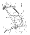
- Figure 1 is a perspective view of the fully deployed hard top roof in an automotive vehicle according to the preferred embodiment of the present invention
- Figure 2 is a partial side view of the hard top roof shown in a fully deployed position of the present invention in relation to an automotive vehicle;
- Figure 3 is a partial perspective view of the hard top roof shown in a fully deployed position of the present invention in relation to an automotive vehicle;
- Figure 4 is a partial side elevational view of the hard top roof shown stowed in the storage compartment in relation to an automotive vehicle;
- Figure 5 is a partial perspective view of the deployed hard top roof structural support members
- Figure 6 is a side view of the front and rear roof panel brackets, partially deployed in an automotive vehicle
- Figure 7 is a blown-up view of the front and rear roof panel brackets, extension arms and drive links;
- Figure 8 is a partial blow-up view of the front roof panel bracket, extension arm, drive link and rotary hydraulic actuator
- Figure 9 is a cross sectional view, taken along line 9-9 of Figure 5, of a main guide bracket
- Figure 10 is a perspective view of the hydraulic system
- Figure 11 is an alternate embodiment of the present invention.
- the present invention is described for illustration purposes embodied in a hydromechanically actuated rigid two-piece hard top roof for an automotive vehicle. It will be appreciated, however, that the principles of the present invention are readily adaptable to a number of other actuation devices which can retract or deploy any multi-section roof top in a vehicle including a soft-top or flexible fabric covered roof where the present actuator is coupled to side rails, or any combined hard and soft top roof.
- Vehicle 10 with a retractable hard top roof device 30 according to the preferred embodiment of the present invention is shown in Figures 1-4.
- Vehicle 10 is constructed with a body 12 and retractable hard top roof 30.
- Body 12 is further divided into a passenger compartment 14 and a miscellaneous storage area or cargo bed 18.
- Passenger compartment 14 has a windshield 15 and a header 16. Header 16 extends transversely across the top of windshield 15.
- a roof storage compartment or area 20 is located between passenger compartment 14 and cargo bed 18.
- Storage compartment 20 is defined by an interior metal seat back panel 22, an exterior metal cargo panel 24, sides 26 of the vehicle body, a floor 17 of the body and a rigid tonneau cover 28.
- Seat back panel 22 is a structural member forming a transverse wall behind passenger compartment 20.
- Exterior cargo panel 24 is also a structural member forming a transverse wall in cargo bed 18.
- Tonneau cover 28 is horizontally disposed on a track on body 12 and hydraulically actuated by a first linear actuator 74.
- Cover 28 provides a closure for storage compartment 20 when hard top roof 30 is in a fully retracted position 77.
- Hard top roof 30 includes a front roof section 32, a rear roof section 36 and a retraction mechanism 40 (see Figures 5-10).
- tonneau cover 28 is moved on the track by first linear actuator 74 to enclose roof 30 in compartment 20.
- actuator 74 when sections 32, 36 respectively are extended in a direction 78 and moved out of storage compartment 20, tonneau cover 28 is moved on the track by actuator 74 to uncover the storage compartment 20.
- tonneau cover 28 is moved by actuator 74 to slide to a position adjacent rear roof section 36 and to enclose storage compartment 20.
- linear actuators may be hydraulic, pneumatic or electric driven and when actuated, the linear actuators are moved to an extended position and a retracted position.
- Tonneau cover 28 is described in U.S. Patent Nos. 5,785,375 and 5,743,587, owned by the assignee of the current application, both of which are incorporated herein by reference.
- front roof section 32 is a rigid panel having an outside surface, an inside surface, a forward edge 33 and a rearward edge 34.
- Front roof section 32 has conventional latching mechanism 31 which is disengageably attachable with header 16 when front and rear roof sections 32, 36 respectively are in a fully extended position 78.
- Forward edge 33 sealingly engages header 16 when a latching mechanism 31 secures the front roof section 32 to windshield 15.
- Rear roof section 36 has an outside or external surface, an inside surface and is further defined by a forward edge 37 and a bottom edge 38.
- Forward edge 37 sealingly engages rearward edge 34 of front roof panel or section 32 when roof 30 is in a fully extended position condition 78.
- Bottom edge 38 has lip seals (not shown) which sealingly engage tonneau cover 28 when rear roof section 36 is deployed or extended in position 78.
- Retraction mechanism 40 is mounted in a cavity 21 in storage compartment 20.
- Retraction mechanism 40 includes a guide portion 42 and a hydraulic portion 70.
- Guide portion 42 has a center post 44 and a pair of spaced apart vertical I-beams 46 which are mounted to floor 17 of compartment 20.
- Vertical I-beams 46 are positioned just inboard of sides 26 in compartment 20.
- I-beams 46 are connected to each other by a transversely extending lift arm 48.
- a pair of lever or pivot arms 49, 49' respectively are provided to move lift arm 48 vertically along I-beams 46. Since pivot arm 49 is a mirror image of pivot arm 49', only arm 49 will be described in detail.
- Pivot arm 49 has a first section and a second section connected at an oblique angle to the first section. One end of pivot arm 49 is pinned to the top portion of center post 44. The other end of pivot arm 49 has a pin which slidingly engages slot 47 in lift arm 48 (see Figure 10). Slot 47 is formed along the transverse axis of arm 48 and adjacent but spaced away from vertical I-beam 46. Slot 47 and pin form a lost motion connection. Pivot arm 49 is moved on vertical I-beam 46 by linear actuation of a pair of second linear actuators 75 of hydraulic portion 70.
- Each second linear actuator 75 is pivotably fastened at its cylindrical end to floor 17 or alternately to center post 44 and at its actuation end, the cylinder is pivotably connected to pivot arm 49 between first section and a second section of pivot arm 49.
- second actuator 75 linearly extends to move against pivot arm 49.
- the pin in slot 47 causes lift arm 48 to move on I-beam 46 in one direction 43 away from floor 17 of compartment 20.
- second actuator 75 linearly move lift arm 48 to move in another direction 41 towards floor 17.
- Vertical beams 46 are also connected to each other at the top end by a transversely extending cross member to add rigidity to the structure. Additionally, a rack and pinion mechanism 65 is provided to stabilize retraction mechanism 40 during operation.
- Rack and pinion mechanism 65 is attached to lift arm 48 and includes shaft 66, and two spur gears 67. Two spaced apart columns 68 with toothed profiles 69 are connected at one end to the cross member and floor 17 at the other end. Columns 68 are substantially parallel and inboard of beams 46.
- Spur gears 67 are attached to shaft 66 and engage the toothed profiles 69.
- Shaft 66 extends longitudinally along lift arm 48 and is conventionally secured to arm 48.
- the rack and pinion mechanism 65 prevents one end of lift arm 48 from cocking relative to the other end and assures that lift arm 48 does not bind on either end when retraction mechanism 40 is operated to deploy or store retractable hard top roof 30 in storage compartment 20.
- Each end of lift arm 48 has main guide brackets 50.
- One bracket 50 engages one end of the vertical beam 46 and the other bracket 50' engages the other end of the vertical beam 46. Because bracket 50 is a mirror image of bracket 50', only guide bracket 50 will be described.
- Main guide bracket 50 is C-shaped in cross-section (see Figure 9) with one side positioned adjacent a flange of the I-beam 46. The other two parallel sides extend from one side and are parallel to the web of the I-beam 46.
- a pair of spaced apart rollers 52 are pivotally mounted to each parallel side of the bracket 50. Each roller 52 is mounted on a shaft which is pinned at one end to one parallel side of the bracket 50. This permits the bracket 50 to engage I-beam 46 with rolling contact thereby reducing the friction to move the lift arm 48 on I-beam 46.
- Bracket 50 has an inboard side 54 and an outboard side 56. Inboard side 52 faces the center post 44 in storage compartment 20. Outboard side 56 faces side 16 of compartment 20 (see Figure 6).
- Front roof section 32 is connected by a front roof linkage mechanism 80 on inboard side 54 and rear roof section 36 is connected by a rear roof linkage mechanism 97 to outboard side 56.
- Front roof linkage mechanism 80 includes a cam action mechanism 60.
- Cam action mechanism 60 includes a contour block 62 which is attached near the top end of the face of I-beam 46 and opposite to the one side of main guide bracket 50.
- Contour block 62 has a cam slot 63.
- cam slot 63 causes front panel main arm 82 to pivot to an angle of between about 30 to 50 degrees from a vertical axis and alternately between about 38 to 42 degrees and further alternatively at substantially about 40 degrees.
- Cam action mechanism 60 functions to assure that front roof section 32 is properly oriented by retraction mechanism 40 prior to being deployed to fully extended position 78.
- Cam action mechanism 60 also functions to assure that roof section 32 is properly oriented by retraction mechanism 40 after being moved to fully retracted position 77 and to nest front roof section 32 in rear roof section 36 prior to being stored in compartment 20 in retracted position in direction 77.
- Main bracket 50 is then moved toward the floor 17 as, for example, when moved in another direction 41 during the storage operation.
- Front roof linkage mechanism 80 also includes a front panel main arm 82, a drive link 86, a front panel first link 89 and a front panel second link 93 (see Figure 8).
- Front panel main arm 82 is pivotably mounted to main guide bracket 50 so that main arm 82 can be rotated to move angularly relative to bracket 50.
- Front panel main arm 82 is a substantially longitudinal flat member with pin 81 that extends from arm 82 so that pin 81 is adjacent to the face of the flange of I-beam 46 and opposite to the one side of main guide bracket 50.
- Pivotable mounting axis 83 is formed at pin 81 and connects main arm 82 to main guide bracket 50 to facilitate angular rotation of arm 82 relative to bracket 50.
- Main arm 82 also has one aperture to receive first link pin to connect one end front panel first link 89 to main arm 82 and another aperture to receive second link pin to connect one end of front panel second link 93 to main arm 82.
- Front panel bracket 96 is pivotably connected to the other end of front panel first link 89 and the other end of front panel second link 93.
- Front roof section 32 is connected to front panel bracket 96.
- Front roof section 32 is connected by a four bar linkage 79 formed by pivotally connecting main arm 82, first link 89, second link 93 and panel bracket 96 together.
- Rotary actuator 72 is a hydraulic motor which hydraulically causes a shaft to rotate and provides rotary motion through a pinion gear 73. Hydraulic motors with rotary actuation are available from Power Packer of Germany and Hoerbiger of Germany. Pinion gear 73 rotates when rotary actuator 72 is made operational by a control unit (not shown).
- Drive link 86 is pivotally connected to front panel first link 89. When drive link 86 moves angularly, the other end of drive link 86 causes four bar linkage 79 to angularly rotate and move from a retracted position 77 to an extended or deployed condition 78 to deploy front roof section 32.
- Rotary actuator 72 is actuated after a potentiometer sensor (or alternately, a limit switch) confirms pivoting of main arm 82 to the desired angle. This assures the proper deployment of front roof section 32 to fully extended position 78.
- Rear roof linkage mechanism 97 includes a bracket 95 pivotably connected to outboard side 56 of guide bracket 50.
- Bracket 95 is connected to rear roof section 36 and is generally a flat plate with an actuate slot 98.
- Arcuate slot 98 engages a pin 99 in outboard side 56.
- a third linear actuator 76 presses against bracket 95 causes bracket 95 to pivot relative to guide bracket 50.
- Pin 99 in slot 98 permits bracket 95 to pivot relative to guide bracket 50 between 0 to 50 degrees and to deploy rear roof section 36 between front roof section 32 and body 12.
- FIG. 10 shows hydraulic portion 70 of retraction mechanism 40.
- Hydraulic portion 70 is driven by an electric motor (not shown) and its operation is controlled by an electronic control device (not shown).
- Hydraulic portion 70 includes rotary actuator 72, a first linear actuator 74, a second linear actuator 75 and a third linear actuator 76.
- first linear actuator 74 linearly moves tonneau cover 28 along a track
- second linear actuator 75 linearly moves pivot arm 49 so that lift arm 48 moves along beams 49, 49' respectively
- third linear actuator 76 linearly moves rear roof section 36 and rotary actuator 72 rotates drive link 86 in order to activate front roof linkage mechanism 80 from fully retracted position 77 to fully extended position 78 and to return from fully extended position 78 to fully retracted position 77.
- a switch (not shown) in passenger compartment 14.
- the switch is connected electrically to the electronic control unit, such as a microprocessor, that controls the operation of retraction mechanism 40.
- the electronic control unit sends a signal to operate an electric motor that is connected to hydraulic pump 71.
- Hydraulic pump 71 is in fluid connection with rotary actuator 72, first linear actuator 74, second linear actuator 75 and third linear actuator 76. Additionally, the electronic control unit controls the operation of actuators 72, 74, 75 and 76.
- First linear actuator 74 is actuated by the electronic control unit to move tonneau cover 28 horizontally along a track on cargo bed 18 to open storage compartment 20.
- a potentiometer sensor senses that tonneau cover 28 has fully traveled along the track and has opened compartment 20. The sensor sends an electrical signal to the electronic control unit confirming that compartment 20 is open. Then, the control unit deactivates first linear actuator 74 and activates second linear actuator 75.
- second linear actuator 75 moves pivot arms 49, 49' respectively to move lift arm 48 vertically along I-beams 46 in one direction 43 to move lift arm 48 from floor 17 to the top end of beams 46.
- a potentiometer sensor senses that lift arm 48 has traveled to the top end of beams 46 and that front panel main arm 82 has pivoted angularly to unnest the front roof section 32 from rear roof section 36 so as to provide clearance between front roof section 32 and rear roof section 36. The sensor sends an electrical signal to the electronic control unit confirming that front roof section 32 is moved angularly relative to rear roof section 36. Then, electronic control unit deactivates second linear actuator and activates rotary actuator 72.
- Rotary actuator 72 is actuated by the electronic control unit to rotate pinion gear 73 and engage internal gears 87 of drive link 86.
- Drive link 86 causes four bar linkage 79 to move from a retracted position 77 to an extended condition 78 to deploy front roof section 32.
- a potentiometer sensor confirms deployment of front roof section 32 to fully extended position 78 and sends an electrical signal to the electronic control unit.
- the electronic control unit deactivates the rotary actuator 72 and activates third linear actuator 76.
- third linear actuator 76 moves bracket 95 to rotate relative to guide bracket 50 and move rear roof section 36 adjacent front roof section 32.
- a potentiometer sensor confirms that rear roof section 36 has been deployed and sends an electrical signal to the electronic control unit. Then, the electronic control unit deactivates the third linear actuator 76 and reactivates first linear actuator 74.
- first linear actuator 74 moves tonneau cover 28 from an open position to a closed position. In the closed position, tonneau cover 28 moves adjacent to the deployed rear roof section 36, sealingly engaged by the lip seals and closes compartment 20.
- a potentiometer sensor detects that the tonneau cover 28 has closed storage compartment 20 and sends an electrical signal to the electronic control unit. Then, the electronic control unit deactivates first linear actuator 74 and causes latching mechanism 31 to engage front roof section 32 to header 16 to deploy and lock roof 30 to vehicle 10.
- retractable hard top roof 30 To store retractable hard top roof 30 from its deployed position, the operator engages the switch in passenger compartment 14 and the electronic control unit reverses the above sequence of events until retractable hard top roof 30 is stored in storage compartment 20 and tonneau cover 28 encloses compartment 20.
- FIG 11 shows an alternate embodiment of a retractable hard top roof device 130 of the present invention. Where the elements are the same as in the preferred embodiment, those numerals will be the same.
- Retractable hard top roof device 130 includes front roof section 32, rear roof section 36 and a retraction mechanism 140.
- Retraction mechanism 140 has a guide portion 142 and hydraulic portion 70.
- Guide portion 142 includes center post 44, I-beams 46, lift arm 48, pivot arms 49, 49' respectively, guide brackets 50, 50' respectively, front roof linkage mechanism 80 and a rear roof linkage mechanism 197.
- Rear roof linkage mechanism 197 is a four bar linkage assembly 199 which is similar to four bar linkage 79. Assembly 199 is connected to outboard side 56 of guide bracket 50.
- Four bar linkage assembly 199 has four links which are actuated by fourth linear actuator 76 to angularly move and rotate rear roof section 36 adjacent front roof section 32. Alternatively, assembly 199 is rotated by a rotary actuator 172 similarly to four bar linkage assembly 79.
- the alternate embodiment of retractable hard top roof 130 is the same as in the preferred embodiment.
- the device may be mounted to the sides of storage compartment on tracks instead of separate I-beams 46.
- the device may also include extra roof sections or additional members to the retraction mechanism.
- a soft top roof can also be used with the present device.
- an electric motor actuator may alternately be employed to deploy retractable roof 30 or any another suitable power transfer mechanism.
- the hard top roof can alternately be stored in a miscellaneous storage area such as a trunk of a conventional sedan or coupe rather than in a roof storage compartment of the presently disclosed pickup truck.
- a miscellaneous storage area such as a trunk of a conventional sedan or coupe rather than in a roof storage compartment of the presently disclosed pickup truck.
- Other materials and dimensions can be substituted for those disclosed. It is intended by the following claims to cover these and any other departures from the disclosed embodiments which fall within the true spirit of this invention.
Abstract
Description
- This invention relates generally to retractable roof structures for automotive vehicles and more specifically to a multi-part hard top convertible roof.
- Automotive vehicles with retractable roofs or tops are commonly referred to as convertibles. Soft top roofs are made of flexible material, which allow the top to be easily folded and stored between open and closed positions. One such example is disclosed in U.S. Patent No. 5,772,274 entitled "Motorized Drive System For a Convertible Roof of an Automotive Vehicle" which issued to Tokarz on June 30, 1998, and is incorporated by reference herein. Unfortunately, soft top roofs are subject to rapid deterioration and are not good noise and heat insulators.
- Manually removeable hard top roofs, on the other hand, possess excellent properties of insulation, water sealing and durability, but are often impractical due to the weight of the tops which makes their manual removal difficult for the average person. Also, they present storage difficulties in the vehicle.
- Retractable hard-top roof systems for convertible automotive vehicles are well known. Traditionally, such retractable hard-top roof systems employ a plurality of rigid roof panels which can be retracted for stowage into the trunk of the automotive vehicle. One such system is disclosed in U.S. Pat. 2,939,742 entitled "Foldable Vehicle Top" which issued to Dardarian et al. on June 7, 1960. The top is designed for swinging movement between a raised and lowered position. A cable is anchored to pulley members to control the effective length of the cable. With continued use of the device, however, the cable may stretch thus requiring frequent adjustment to the deployment mechanism. Additionally, the top is stored in the trunk thus pre-empting valuable storage space.
- Other examples of such systems are disclosed in U.S. Pat. Nos.: 5,195,798 entitled "Retractable Roof For Vehicles" which issued to Klein et al. on March 23, 1993; 4,854,634 entitled "Upper Body Structure For A Convertible Vehicle" which issued to Shiraishi et al. on Aug. 8, 1989; 5,979,970 entitled "Roof Assembly for a Convertible Vehicle" which issued on November 9, 1999 to Rothe et al.; 5,779,299 entitled "Apparatus for Achieving Automotive Vehicle Roof Insulation" which issued to Purcell, et al. on July 14, 1998; and 5,785,375 entitled "Retractable Hard-top for an Automotive Vehicle" which issued to Alexander, et al. on July 28, 1998; all of which are incorporated by reference herein. Thus, there is a need for a simple two part convertible roof that is compact, rugged and minimizes the need for adjustment to the retraction mechanism.
- In accordance with the preferred embodiment of the present invention, a retractable hard-top roof for an automobile vehicle is provided. In another aspect of the present invention, a retraction mechanism couples a rear roof section and a front roof section to a vehicle. A further aspect of the present invention employs a lever arm which is elongated in a generally cross-car direction, driven by an automatic actuator, which has one end coupled to a pivot and an opposite end which can move in a generally vertical direction.
- In still another aspect of the present invention, a method for deploying a hard-top roof from a storage compartment of an automotive vehicle is disclosed. The method includes moving a rigid front roof section and a rigid rear roof section along a generally vertical axis from the storage compartment. Then, angularly rotating the front roof section from the substantially vertical axis to separate from the rear roof section. Next, rotatably deploying the front roof section to an extended position. Then, angularly translating the rear roof section from the substantially vertical axis to move the rear roof section between the front roof section and the body of the vehicle.
- The present invention is advantageous over conventional devices since the present invention provides a retractable roof with a front roof portion that is angularly and rotatably extended and is stored so that the front roof portion is nested in the rear roof portion that is simple, compact, rugged and easy to operate. Additionally, the device reduces the need for adjustments to the retraction mechanism by providing a robust hydromechanical deployment unit. These and other features and advantages of the present invention will become apparent from the subsequent description and claims taken in conjunction with the accompanying drawings.
- Figure 1 is a perspective view of the fully deployed hard top roof in an automotive vehicle according to the preferred embodiment of the present invention;
- Figure 2 is a partial side view of the hard top roof shown in a fully deployed position of the present invention in relation to an automotive vehicle;
- Figure 3 is a partial perspective view of the hard top roof shown in a fully deployed position of the present invention in relation to an automotive vehicle;
- Figure 4 is a partial side elevational view of the hard top roof shown stowed in the storage compartment in relation to an automotive vehicle;
- Figure 5 is a partial perspective view of the deployed hard top roof structural support members;
- Figure 6 is a side view of the front and rear roof panel brackets, partially deployed in an automotive vehicle;
- Figure 7 is a blown-up view of the front and rear roof panel brackets, extension arms and drive links;
- Figure 8 is a partial blow-up view of the front roof panel bracket, extension arm, drive link and rotary hydraulic actuator;
- Figure 9 is a cross sectional view, taken along line 9-9 of Figure 5, of a main guide bracket;
- Figure 10 is a perspective view of the hydraulic system; and
- Figure 11 is an alternate embodiment of the present invention.
- The present invention is described for illustration purposes embodied in a hydromechanically actuated rigid two-piece hard top roof for an automotive vehicle. It will be appreciated, however, that the principles of the present invention are readily adaptable to a number of other actuation devices which can retract or deploy any multi-section roof top in a vehicle including a soft-top or flexible fabric covered roof where the present actuator is coupled to side rails, or any combined hard and soft top roof.
- An
automobile vehicle 10 with a retractable hardtop roof device 30 according to the preferred embodiment of the present invention is shown in Figures 1-4.Vehicle 10 is constructed with abody 12 and retractable hardtop roof 30.Body 12 is further divided into apassenger compartment 14 and a miscellaneous storage area orcargo bed 18.Passenger compartment 14 has awindshield 15 and aheader 16.Header 16 extends transversely across the top ofwindshield 15. A roof storage compartment orarea 20 is located betweenpassenger compartment 14 andcargo bed 18. -
Storage compartment 20 is defined by an interior metalseat back panel 22, an exteriormetal cargo panel 24,sides 26 of the vehicle body, afloor 17 of the body and arigid tonneau cover 28.Seat back panel 22 is a structural member forming a transverse wall behindpassenger compartment 20.Exterior cargo panel 24 is also a structural member forming a transverse wall incargo bed 18. -
Tonneau cover 28 is horizontally disposed on a track onbody 12 and hydraulically actuated by a firstlinear actuator 74.Cover 28 provides a closure forstorage compartment 20 when hardtop roof 30 is in a fully retractedposition 77. Hardtop roof 30 includes afront roof section 32, arear roof section 36 and a retraction mechanism 40 (see Figures 5-10). Thus, after front andrear roof sections direction 77 and are stored instorage compartment 20,tonneau cover 28 is moved on the track by firstlinear actuator 74 to encloseroof 30 incompartment 20. And whensections direction 78 and moved out ofstorage compartment 20,tonneau cover 28 is moved on the track byactuator 74 to uncover thestorage compartment 20. Afterroof 30 is deployed,tonneau cover 28 is moved byactuator 74 to slide to a position adjacentrear roof section 36 and to enclosestorage compartment 20. Alternately, linear actuators may be hydraulic, pneumatic or electric driven and when actuated, the linear actuators are moved to an extended position and a retracted position. Tonneaucover 28 is described in U.S. Patent Nos. 5,785,375 and 5,743,587, owned by the assignee of the current application, both of which are incorporated herein by reference. - As best shown in Figures 5-10,
front roof section 32 is a rigid panel having an outside surface, an inside surface, aforward edge 33 and arearward edge 34.Front roof section 32 hasconventional latching mechanism 31 which is disengageably attachable withheader 16 when front andrear roof sections position 78.Forward edge 33 sealingly engagesheader 16 when alatching mechanism 31 secures thefront roof section 32 to windshield 15. -
Rear roof section 36 has an outside or external surface, an inside surface and is further defined by aforward edge 37 and abottom edge 38. Forward edge 37 sealingly engages rearward edge 34 of front roof panel orsection 32 whenroof 30 is in a fullyextended position condition 78.Bottom edge 38 has lip seals (not shown) which sealingly engagetonneau cover 28 whenrear roof section 36 is deployed or extended inposition 78. -
Retraction mechanism 40 is mounted in acavity 21 instorage compartment 20.Retraction mechanism 40 includes aguide portion 42 and ahydraulic portion 70.Guide portion 42 has acenter post 44 and a pair of spaced apart vertical I-beams 46 which are mounted tofloor 17 ofcompartment 20. Vertical I-beams 46 are positioned just inboard ofsides 26 incompartment 20. I-beams 46 are connected to each other by a transversely extendinglift arm 48. A pair of lever or pivotarms 49, 49' respectively are provided to movelift arm 48 vertically along I-beams 46. Sincepivot arm 49 is a mirror image of pivot arm 49', onlyarm 49 will be described in detail. -
Pivot arm 49 has a first section and a second section connected at an oblique angle to the first section. One end ofpivot arm 49 is pinned to the top portion ofcenter post 44. The other end ofpivot arm 49 has a pin which slidingly engagesslot 47 in lift arm 48 (see Figure 10).Slot 47 is formed along the transverse axis ofarm 48 and adjacent but spaced away from vertical I-beam 46.Slot 47 and pin form a lost motion connection.Pivot arm 49 is moved on vertical I-beam 46 by linear actuation of a pair of secondlinear actuators 75 ofhydraulic portion 70. Each secondlinear actuator 75 is pivotably fastened at its cylindrical end tofloor 17 or alternately to centerpost 44 and at its actuation end, the cylinder is pivotably connected to pivotarm 49 between first section and a second section ofpivot arm 49. When actuated,second actuator 75 linearly extends to move againstpivot arm 49. The pin inslot 47 causes liftarm 48 to move on I-beam 46 in onedirection 43 away fromfloor 17 ofcompartment 20. When retracted,second actuator 75 linearly movelift arm 48 to move in anotherdirection 41 towardsfloor 17. -
Vertical beams 46 are also connected to each other at the top end by a transversely extending cross member to add rigidity to the structure. Additionally, a rack andpinion mechanism 65 is provided to stabilizeretraction mechanism 40 during operation. Rack andpinion mechanism 65 is attached to liftarm 48 and includesshaft 66, and two spur gears 67. Two spaced apartcolumns 68 with toothed profiles 69 are connected at one end to the cross member andfloor 17 at the other end.Columns 68 are substantially parallel and inboard ofbeams 46. Spur gears 67 are attached toshaft 66 and engage the toothed profiles 69.Shaft 66 extends longitudinally alonglift arm 48 and is conventionally secured toarm 48. Whenlift arm 48 is moved alongbeams 46, the rack andpinion mechanism 65 prevents one end oflift arm 48 from cocking relative to the other end and assures thatlift arm 48 does not bind on either end whenretraction mechanism 40 is operated to deploy or store retractable hardtop roof 30 instorage compartment 20. - Each end of
lift arm 48 hasmain guide brackets 50. Onebracket 50 engages one end of thevertical beam 46 and the other bracket 50' engages the other end of thevertical beam 46. Becausebracket 50 is a mirror image of bracket 50', only guidebracket 50 will be described. -
Main guide bracket 50 is C-shaped in cross-section (see Figure 9) with one side positioned adjacent a flange of the I-beam 46. The other two parallel sides extend from one side and are parallel to the web of the I-beam 46. A pair of spaced apartrollers 52 are pivotally mounted to each parallel side of thebracket 50. Eachroller 52 is mounted on a shaft which is pinned at one end to one parallel side of thebracket 50. This permits thebracket 50 to engage I-beam 46 with rolling contact thereby reducing the friction to move thelift arm 48 on I-beam 46.Bracket 50 has aninboard side 54 and anoutboard side 56.Inboard side 52 faces thecenter post 44 instorage compartment 20.Outboard side 56 facesside 16 of compartment 20 (see Figure 6). -
Front roof section 32 is connected by a frontroof linkage mechanism 80 oninboard side 54 andrear roof section 36 is connected by a rearroof linkage mechanism 97 tooutboard side 56. Frontroof linkage mechanism 80 includes acam action mechanism 60. -
Cam action mechanism 60 includes acontour block 62 which is attached near the top end of the face of I-beam 46 and opposite to the one side ofmain guide bracket 50.Contour block 62 has acam slot 63. Whenmain bracket 50 is moved toward the top ofvertical beam 46 as, for example, when moved in onedirection 43 during deployment of hardtop roof 30, a pin orcam follower 81 engagescam slot 63. As this occurs,cam slot 63 causes front panelmain arm 82 to pivot to an angle of between about 30 to 50 degrees from a vertical axis and alternately between about 38 to 42 degrees and further alternatively at substantially about 40 degrees.Cam action mechanism 60 functions to assure thatfront roof section 32 is properly oriented byretraction mechanism 40 prior to being deployed to fullyextended position 78.Cam action mechanism 60 also functions to assure thatroof section 32 is properly oriented byretraction mechanism 40 after being moved to fully retractedposition 77 and to nestfront roof section 32 inrear roof section 36 prior to being stored incompartment 20 in retracted position indirection 77.Main bracket 50 is then moved toward thefloor 17 as, for example, when moved in anotherdirection 41 during the storage operation. - Front
roof linkage mechanism 80 also includes a front panelmain arm 82, adrive link 86, a front panel first link 89 and a front panel second link 93 (see Figure 8). Front panelmain arm 82 is pivotably mounted tomain guide bracket 50 so thatmain arm 82 can be rotated to move angularly relative tobracket 50. Front panelmain arm 82 is a substantially longitudinal flat member withpin 81 that extends fromarm 82 so thatpin 81 is adjacent to the face of the flange of I-beam 46 and opposite to the one side ofmain guide bracket 50.Pivotable mounting axis 83 is formed atpin 81 and connectsmain arm 82 tomain guide bracket 50 to facilitate angular rotation ofarm 82 relative tobracket 50.Main arm 82 also has one aperture to receive first link pin to connect one end front panel first link 89 tomain arm 82 and another aperture to receive second link pin to connect one end of front panel second link 93 tomain arm 82.Front panel bracket 96 is pivotably connected to the other end of front panel first link 89 and the other end of front panelsecond link 93.Front roof section 32 is connected tofront panel bracket 96.Front roof section 32 is connected by a fourbar linkage 79 formed by pivotally connectingmain arm 82,first link 89,second link 93 andpanel bracket 96 together. - Four
bar linkage 79 is actuated by arotary actuator 72 ofhydraulic portion 70 which is attached to the front panelmain arm 82.Rotary actuator 72 is a hydraulic motor which hydraulically causes a shaft to rotate and provides rotary motion through apinion gear 73. Hydraulic motors with rotary actuation are available from Power Packer of Germany and Hoerbiger of Germany.Pinion gear 73 rotates whenrotary actuator 72 is made operational by a control unit (not shown). -
Interior gear teeth 87 at one end indrive link 86 engage.Pinion gear 73 is caused to rotate by hydraulic fluid from a hydraulic pump 71.Pinion gear 73 engagesgear teeth 87 and whenrotary actuator 72 is operational,pinion gear 73 rotates, thereby causingdrive link 86 to rotate and move angularly about its one end. Drivelink 86 is pivotally connected to front panelfirst link 89. Whendrive link 86 moves angularly, the other end ofdrive link 86 causes fourbar linkage 79 to angularly rotate and move from a retractedposition 77 to an extended or deployedcondition 78 to deployfront roof section 32. -
Rotary actuator 72 is actuated after a potentiometer sensor (or alternately, a limit switch) confirms pivoting ofmain arm 82 to the desired angle. This assures the proper deployment offront roof section 32 to fullyextended position 78. - Rear
roof linkage mechanism 97 includes abracket 95 pivotably connected tooutboard side 56 ofguide bracket 50.Bracket 95 is connected torear roof section 36 and is generally a flat plate with anactuate slot 98.Arcuate slot 98 engages a pin 99 inoutboard side 56. When actuated, a thirdlinear actuator 76 presses againstbracket 95 causesbracket 95 to pivot relative to guidebracket 50. Pin 99 inslot 98permits bracket 95 to pivot relative to guidebracket 50 between 0 to 50 degrees and to deployrear roof section 36 betweenfront roof section 32 andbody 12. - Figure 10 shows
hydraulic portion 70 ofretraction mechanism 40.Hydraulic portion 70 is driven by an electric motor (not shown) and its operation is controlled by an electronic control device (not shown).Hydraulic portion 70 includesrotary actuator 72, a firstlinear actuator 74, a secondlinear actuator 75 and a thirdlinear actuator 76. - As stated earlier, first
linear actuator 74 linearly movestonneau cover 28 along a track, secondlinear actuator 75 linearly movespivot arm 49 so thatlift arm 48 moves alongbeams 49, 49' respectively, thirdlinear actuator 76 linearly movesrear roof section 36 androtary actuator 72 rotates drivelink 86 in order to activate frontroof linkage mechanism 80 from fully retractedposition 77 to fullyextended position 78 and to return from fully extendedposition 78 to fully retractedposition 77. - In operation, to deploy retractable hard
top roof 30, the operator engages a switch (not shown) inpassenger compartment 14. The switch is connected electrically to the electronic control unit, such as a microprocessor, that controls the operation ofretraction mechanism 40. The electronic control unit sends a signal to operate an electric motor that is connected to hydraulic pump 71. Hydraulic pump 71 is in fluid connection withrotary actuator 72, firstlinear actuator 74, secondlinear actuator 75 and thirdlinear actuator 76. Additionally, the electronic control unit controls the operation ofactuators - First
linear actuator 74 is actuated by the electronic control unit to movetonneau cover 28 horizontally along a track oncargo bed 18 to openstorage compartment 20. A potentiometer sensor senses thattonneau cover 28 has fully traveled along the track and has openedcompartment 20. The sensor sends an electrical signal to the electronic control unit confirming thatcompartment 20 is open. Then, the control unit deactivates firstlinear actuator 74 and activates secondlinear actuator 75. - When activated, second
linear actuator 75 moves pivotarms 49, 49' respectively to movelift arm 48 vertically along I-beams 46 in onedirection 43 to movelift arm 48 fromfloor 17 to the top end ofbeams 46. A potentiometer sensor senses that liftarm 48 has traveled to the top end ofbeams 46 and that front panelmain arm 82 has pivoted angularly to unnest thefront roof section 32 fromrear roof section 36 so as to provide clearance betweenfront roof section 32 andrear roof section 36. The sensor sends an electrical signal to the electronic control unit confirming thatfront roof section 32 is moved angularly relative torear roof section 36. Then, electronic control unit deactivates second linear actuator and activatesrotary actuator 72. -
Rotary actuator 72 is actuated by the electronic control unit to rotatepinion gear 73 and engageinternal gears 87 ofdrive link 86. Drivelink 86 causes fourbar linkage 79 to move from a retractedposition 77 to anextended condition 78 to deployfront roof section 32. A potentiometer sensor confirms deployment offront roof section 32 to fullyextended position 78 and sends an electrical signal to the electronic control unit. Upon receiving the signal from the sensor, the electronic control unit deactivates therotary actuator 72 and activates thirdlinear actuator 76. - When activated, third
linear actuator 76moves bracket 95 to rotate relative to guidebracket 50 and moverear roof section 36 adjacentfront roof section 32. A potentiometer sensor confirms thatrear roof section 36 has been deployed and sends an electrical signal to the electronic control unit. Then, the electronic control unit deactivates the thirdlinear actuator 76 and reactivates firstlinear actuator 74. - When reactivated, first
linear actuator 74moves tonneau cover 28 from an open position to a closed position. In the closed position,tonneau cover 28 moves adjacent to the deployedrear roof section 36, sealingly engaged by the lip seals and closescompartment 20. A potentiometer sensor detects that thetonneau cover 28 has closedstorage compartment 20 and sends an electrical signal to the electronic control unit. Then, the electronic control unit deactivates firstlinear actuator 74 andcauses latching mechanism 31 to engagefront roof section 32 toheader 16 to deploy and lockroof 30 tovehicle 10. - To store retractable hard
top roof 30 from its deployed position, the operator engages the switch inpassenger compartment 14 and the electronic control unit reverses the above sequence of events until retractable hardtop roof 30 is stored instorage compartment 20 andtonneau cover 28 enclosescompartment 20. - Figure 11 shows an alternate embodiment of a retractable hard
top roof device 130 of the present invention. Where the elements are the same as in the preferred embodiment, those numerals will be the same. Retractable hardtop roof device 130 includesfront roof section 32,rear roof section 36 and aretraction mechanism 140.Retraction mechanism 140 has aguide portion 142 andhydraulic portion 70. -
Guide portion 142 includescenter post 44, I-beams 46,lift arm 48, pivotarms 49, 49' respectively, guidebrackets 50, 50' respectively, frontroof linkage mechanism 80 and a rearroof linkage mechanism 197. Rearroof linkage mechanism 197 is a four bar linkage assembly 199 which is similar to fourbar linkage 79. Assembly 199 is connected tooutboard side 56 ofguide bracket 50. Four bar linkage assembly 199 has four links which are actuated by fourthlinear actuator 76 to angularly move and rotaterear roof section 36 adjacentfront roof section 32. Alternatively, assembly 199 is rotated by arotary actuator 172 similarly to fourbar linkage assembly 79. In all other respects, the alternate embodiment of retractable hardtop roof 130 is the same as in the preferred embodiment. - While it is apparent that the embodiments of the invention disclosed are well calculated to provide the advantages and features above stated, it will be appreciated that the invention is susceptible to modification, variation, and change without departing from the proper scope or fair meaning of the subjoined claims. For example, the device may be mounted to the sides of storage compartment on tracks instead of separate I-
beams 46. The device may also include extra roof sections or additional members to the retraction mechanism. A soft top roof can also be used with the present device. While the device was described with hydraulic actuators, an electric motor actuator may alternately be employed to deployretractable roof 30 or any another suitable power transfer mechanism. Furthermore, the hard top roof can alternately be stored in a miscellaneous storage area such as a trunk of a conventional sedan or coupe rather than in a roof storage compartment of the presently disclosed pickup truck. Other materials and dimensions can be substituted for those disclosed. It is intended by the following claims to cover these and any other departures from the disclosed embodiments which fall within the true spirit of this invention.
Claims (28)
- An automotive vehicle apparatus comprising:a convertible roof being moveable in at least a fore-and-aft direction between a raised position and a retracted position; anda back window attached to and always moving with at least a portion of the convertible roof; anda retraction mechanism coupled to the convertible roof to operably drive the roof between the positions, the retraction mechanism including at least one lever arm and an automatic actuator, the lever arm being elongated in a substantially cross-car direction substantially perpendicular to the fore-and-aft direction, a first end of the lever arm operably moving in a substantially vertical direction in response to actuation of the actuator.
- The apparatus of claim 1 further comprising a substantially stationary pivot, and a second end of the lever arm coupled to the pivot, the actuator being located substantially between the ends of the lever arm.
- The apparatus of claim 2 wherein the retraction mechanism includes a second lever arm and a second automatic actuator, the second lever arm being elongated in the substantially cross-car direction and having a first end moveable in the substantially vertical direction in response to actuation of the second actuator.
- The apparatus of claim 3 further comprising substantially vertical and stationary members coupled to the convertible roof to allow sliding movement of the roof relative to the vertical members at least partially in response to movement of the lever arms, wherein the first ends of the lever arms are outboard ends.
- The apparatus of claim 1, further comprising a four-bar linkage coupled to a front section of the convertible roof, and a rear roof linkage coupled to a rear section of the convertible roof.
- The apparatus of claim 5, further comprising an automatically powered rotary actuator operably driving the four-bar linkage.
- The apparatus of claim 1, further comprising a rack and pinion mechanism operably assisting in guiding the vertical movement of the lever arm.
- The apparatus of claim 1, further comprising:a substantially vertical and stationary guide;a member moveably coupled to the guide, movement of the lever arm operably causing the member to upwardly move along the guide;a cam coupled to one of the guide and the member;a cam follower operably engaging the cam when the member is near the top of the guide; andthe cam causing a forward portion of the convertible roof to rotate relative to a moveable rearward portion of the convertible roof.
- The apparatus of claim 8, wherein the forward and rearward portions of the convertible roof are separate hard top roof sections.
- The apparatus of any one of the preceding claims, wherein the convertible roof is a retractable hard top roof.
- The apparatus of claim 10, wherein the convertible roof includes at least two substantially rigid roof sections.
- An automotive vehicle apparatus comprising:a convertible roof section having at least a front hard top roof section and a rear hard top roof section;a substantially vertical and stationary guide;an automatic actuator;a member movably coupled to the guide, energization of the actuator operably causing the member to move upwardly along the guide;a cam coupled to one of the guide and the member; anda cam follower operably engaging the cam when the member is near the top of the guide;the cam causing one of the front and rear roof sections to rotate relative to the other when the front and rear roof sections are both adjacent a roof storage area.
- The apparatus of claim 12, further comprising a rack and pinion mechanism coupled to the convertible roof.
- The apparatus of claim 12 or claim 13, further comprising a back window always moving with the rear roof section.
- The apparatus of any one of claims 12 to 14, further comprising at least a four-bar linkage coupling the front roof section to the rear roof section.
- The apparatus of any one of claims 12 to 15, wherein the cam follower is automatically disengageable from the cam when the front roof section is advanced toward its raised position.
- The apparatus of any one of claims 11 to 16, wherein the roof sections are stored in a substantially vertical orientation.
- The apparatus of any one of claims 11 to 17, wherein external surfaces of the roof sections are stored in a rearwardly facing direction.
- The apparatus of any one of the preceding claims, further comprising a miscellaneous storage area and a roof storage area, the convertible roof being stored in the roof storage area without obstructing access to the miscellaneous storage area.
- A method of operating a hard top convertible roof with a guide, at least one linkage mechanism and at least one actuator, the roof having at least substantially rigid front and rear hard top roof sections, the method comprising:(a) lowering the linkage mechanism relative to the guide by automatic actuation of at least the actuator;(b) retracting the substantially rigid hard top roof sections;(c) rotating one roof section relative to the other roof section by a camming action during retraction of the roof sections; and(d) moving at least portions of the roof sections closer together through the camming section action to reduce storage space needed for the roof sections when retracted.
- The method of claim 20, further comprising pivoting an elongated arm about a pivot axis located adjacent a cross-car center line in order to retract the convertible roof.
- The method of claim 21, further comprising energizing a fluid powered actuator to drive the arm.
- The method of any one of claims 20 to 22, further comprising storing the roof sections in a substantially parallel and substantially vertical orientation with their external surfaces facing substantially the same direction.
- A method of operating a hard top convertible roof of an automotive vehicle with a retraction mechanism, the roof having a back window, the method comprising:(a) automatically energizing the retraction mechanism to move at least a portion of a cross-car extending lever arm along a substantially vertical plane from a first position to a second and offset position;(b) retracting the hard top convertible roof from a raised position to a retracted position in response to step (a);(c) always moving the back window with the hard top convertible roof; and(d) orienting the majority of the hard top convertible roof in a substantially vertical direction when in the retracted position.
- The method of claim 24, further comprising:(a) energizing a first actuator;(b) rotating the lever arm coupled to and in response to the energization of the first actuator;(c) simultaneously energizing a second actuator; and(d) rotating a second lever arm coupled to and in response to the energization of the second actuator.
- The method of claim 25, further comprising rotating at least one of the lever arms about a fulcrum coupled to a substantially vertically extending post.
- The method of any one of claims 24 to 26, further comprising:(a) retracting a front roof section of the hard top convertible roof to a substantially vertical position when fully retracted; and(b) retracting a rear roof section of the hard top convertible roof to a substantially vertical position behind the front roof section in the vehicle when fully retracted.
- The method of any one of claims 24 to 27, further comprising:(a) camming a first roof section of the hard top convertible roof relative to a second roof section of the hard top convertible roof during their retraction; and(b) moving the roof sections closer together through the camming to reduce storage space needed in the vehicle for the roof sections when fully retracted.
Applications Claiming Priority (2)
| Application Number | Priority Date | Filing Date | Title |
|---|---|---|---|
| US09/930,564 US6497447B1 (en) | 2001-08-15 | 2001-08-15 | Convertible hard top for vehicles |
| US930564 | 2001-08-15 |
Publications (2)
| Publication Number | Publication Date |
|---|---|
| EP1284210A2 true EP1284210A2 (en) | 2003-02-19 |
| EP1284210A3 EP1284210A3 (en) | 2003-04-09 |
Family
ID=25459448
Family Applications (1)
| Application Number | Title | Priority Date | Filing Date |
|---|---|---|---|
| EP02255362A Withdrawn EP1284210A3 (en) | 2001-08-15 | 2002-07-31 | Convertible hard top for vehicles |
Country Status (2)
| Country | Link |
|---|---|
| US (1) | US6497447B1 (en) |
| EP (1) | EP1284210A3 (en) |
Cited By (1)
| Publication number | Priority date | Publication date | Assignee | Title |
|---|---|---|---|---|
| WO2007000563A1 (en) * | 2005-06-29 | 2007-01-04 | Ford Global Technologies, Llc | A cabriolet motor vehicle having a stowable roof |
Families Citing this family (21)
| Publication number | Priority date | Publication date | Assignee | Title |
|---|---|---|---|---|
| DE10112344C1 (en) * | 2001-03-13 | 2002-08-29 | Cts Fahrzeug Dachsysteme Gmbh | Convertible top compartment lid in a convertible vehicle |
| US6659534B2 (en) * | 2001-08-15 | 2003-12-09 | Asc Incorporated | Hard-top convertible roof system |
| DE10139354A1 (en) * | 2001-08-17 | 2003-03-13 | Karmann Gmbh W | Convertible car |
| US7093884B2 (en) * | 2002-08-15 | 2006-08-22 | Asc Incorporated | Bulkhead module for an automotive vehicle having a convertible roof |
| US6857684B2 (en) * | 2002-08-15 | 2005-02-22 | Asc Incorporated | Hard-top convertible roof apparatus |
| US7140666B2 (en) * | 2002-08-15 | 2006-11-28 | Asc Incorporated | Latch for an automobile vehicle having a convertible roof |
| DE10254365A1 (en) * | 2002-11-21 | 2004-06-17 | Wilhelm Karmann Gmbh | motor vehicle |
| US6695385B1 (en) * | 2003-03-31 | 2004-02-24 | Asc Incorporated | Vehicle convertible roof |
| DE10326980B4 (en) * | 2003-06-12 | 2006-03-30 | Webasto Ag | Vehicle convertible from a pickup to a convertible |
| DE10340017B3 (en) * | 2003-08-28 | 2004-08-12 | Cts Fahrzeug-Dachsysteme Gmbh | Rear cover for cabriolet automobile using multiple linkage mechanism for movement of rear cover between closed position and raised position providing access to storage compartment for cabriolet roof |
| US7100964B2 (en) * | 2004-08-23 | 2006-09-05 | Asc Incorporated | Convertible roof system |
| US7347482B2 (en) * | 2004-08-31 | 2008-03-25 | Specialty Vehicle Acquisition Corp. | Tonneau cover system |
| ITTO20040151U1 (en) * | 2004-11-18 | 2005-02-18 | Fioravanti Srl | OPENABLE ROOF SYSTEM FOR A VEHICLE. |
| US7520556B2 (en) * | 2005-07-19 | 2009-04-21 | Jay Martin | Retractable vehicle roof system with storage area lid |
| US7229122B2 (en) * | 2005-07-19 | 2007-06-12 | Martin Jay R | Motor assisted movement of vehicle top with storage area lid |
| US7226109B2 (en) * | 2005-07-19 | 2007-06-05 | Martin Jay R | Movement of vehicle top over recessed accessible storage area lid and method to preserve vehicle profile |
| DE102006039014A1 (en) * | 2006-08-19 | 2008-02-28 | Magna Car Top Systems Gmbh | Multi-part roof for a motor vehicle |
| US8042856B2 (en) * | 2007-09-27 | 2011-10-25 | Magna Car Top Systems Gmbh | Compactly stored tri-fold convertible top |
| JP6654075B2 (en) * | 2016-03-18 | 2020-02-26 | ベバスト ジャパン株式会社 | Back window seal structure for retractable roof vehicles |
| US10518617B2 (en) * | 2018-02-28 | 2019-12-31 | Honda Motor Co., Ltd. | Retractable headliner for vehicle convertible system |
| AU2020328465A1 (en) * | 2019-08-12 | 2022-03-03 | Oakmoore Pty Ltd | System and method for rollcover activation and deactivation |
Citations (8)
| Publication number | Priority date | Publication date | Assignee | Title |
|---|---|---|---|---|
| US2939742A (en) | 1958-04-03 | 1960-06-07 | Gen Motors Corp | Foldable vehicle top |
| US4854634A (en) | 1986-10-02 | 1989-08-08 | Mazda Motor Corporation | Upper body structure for a convertible vehicle |
| US5195798A (en) | 1990-11-29 | 1993-03-23 | Mercedes-Benz Ag | Retractable roof for vehicles |
| US5743587A (en) | 1993-12-29 | 1998-04-28 | Asc Incorporated | Apparatus for use in an automotive vehicle having a convertible roof system |
| US5772274A (en) | 1995-01-31 | 1998-06-30 | Asc Incorporated | Motorized drive system for a convertible roof of an automotive vehicle |
| US5779299A (en) | 1995-06-07 | 1998-07-14 | Asc Incorporated | Apparatus for achieving automotive vehicle roof isolation |
| US5785375A (en) | 1993-12-29 | 1998-07-28 | Asc Incorporated | Retractable hard-top for an automotive vehicle |
| US5979970A (en) | 1996-11-23 | 1999-11-09 | Wilhelm Karmann Gmbh | Roof assembly for a convertible vehicle |
Family Cites Families (104)
| Publication number | Priority date | Publication date | Assignee | Title |
|---|---|---|---|---|
| US404405A (en) | 1889-06-04 | Carriage | ||
| BE493260A (en) | ||||
| US1184734A (en) | 1915-02-04 | 1916-05-30 | Russell M Freeman | Folding automobile-top. |
| US1784279A (en) | 1929-01-07 | 1930-12-09 | Ellerbeck Ben Brown | Convertible automobile top |
| US2007873A (en) | 1931-12-19 | 1935-07-09 | Paulin Georges Auguste | Vehicle body top capable of being stowed away |
| US2076243A (en) | 1932-09-08 | 1937-04-06 | Briggs Mfg Co | Collapsible top for automobiles |
| US1988346A (en) | 1933-02-16 | 1935-01-15 | Willys P Wagner | Automobile body construction |
| GB413467A (en) | 1933-05-09 | 1934-07-19 | Ernest Metcalfe | Improvements in and connected with folding hoods for motor vehicles |
| DE646381C (en) | 1935-05-09 | 1937-06-12 | Klara Marie Heti Flemming Geb | Roof for motor vehicles |
| US2580486A (en) | 1948-06-05 | 1952-01-01 | Briggs Mfg Co | Collapsible top for vehicles |
| US2564446A (en) | 1948-09-29 | 1951-08-14 | John B Parsons | Rear flap operator for convertible tops |
| US2586355A (en) | 1949-03-16 | 1952-02-19 | Leven Roland Manuel | Belt |
| BE500588A (en) | 1951-01-12 | |||
| US2704225A (en) | 1951-07-05 | 1955-03-15 | Kaiser Motors Corp | Convertible automobile top |
| US2714035A (en) | 1952-09-26 | 1955-07-26 | Gen Motors Corp | Retractable automobile back window |
| US2768025A (en) | 1952-11-26 | 1956-10-23 | Ford Motor Co | Retractible rigid automobile top |
| US2747921A (en) | 1952-12-22 | 1956-05-29 | Gen Motors Corp | Retractable rear window for an automobile |
| US2747928A (en) | 1953-01-13 | 1956-05-29 | Gen Motors Corp | Folding top compartment cover |
| US2768024A (en) | 1953-02-09 | 1956-10-23 | Ford Motor Co | Retractable rigid automobile top |
| DE1117420B (en) | 1953-11-20 | 1961-11-16 | Hermann Flemming | Convertible top for passenger cars |
| US2856231A (en) | 1954-04-05 | 1958-10-14 | Mcculloch Motors Corp | Rigid retractable automobile top with automatic latching means |
| US2836457A (en) | 1955-06-16 | 1958-05-27 | Berman Eugene | Let-down type vehicle closure |
| US2869923A (en) | 1955-07-29 | 1959-01-20 | Mulichak Steven | Retractable hard top convertible |
| US2841441A (en) | 1956-04-13 | 1958-07-01 | Lou A Evans | Convertible motor vehicle body having a rigid top |
| US2919156A (en) | 1957-10-25 | 1959-12-29 | Robert W Dodge | Collapsible cab structure |
| US2997337A (en) | 1958-05-28 | 1961-08-22 | Ford Motor Co | Motor vehicle body foldable top |
| US3059962A (en) | 1960-03-02 | 1962-10-23 | Ford Motor Co | Vehicle body with retractable rigid top |
| GB978638A (en) | 1961-05-24 | 1964-12-23 | Hermann Flemming | Collapsible roof structure for motor vehicles |
| US3357738A (en) | 1965-10-11 | 1967-12-12 | Bourlier Jean | Automobile top |
| DE1505474A1 (en) | 1965-10-11 | 1969-07-31 | Jean Bourlier | Rigid folding roof for a motor vehicle |
| US3375037A (en) | 1966-05-23 | 1968-03-26 | Chrysler Corp | Retractable hardtop |
| US3377099A (en) | 1966-09-19 | 1968-04-09 | Gen Motors Corp | Compartment closure for vehicle body |
| US3575464A (en) | 1969-09-29 | 1971-04-20 | Gen Motors Corp | Folding retractable hard top |
| DE2327486C2 (en) | 1973-05-30 | 1975-04-30 | Daimler-Benz Ag, 7000 Stuttgart | Control of a linkage of a folding top of motor vehicles that is hinged to sunk-in consoles |
| DE2647236A1 (en) | 1976-10-20 | 1978-04-27 | Daimler Benz Ag | MOTOR VEHICLES, IN PARTICULAR PASSENGER CARS, WITH A SLIDING UPPER CAR BODY SECTION |
| CH650980A5 (en) | 1982-05-03 | 1985-08-30 | Paul Rollman | Convertible vehicle |
| US4634171A (en) | 1982-06-18 | 1987-01-06 | D-M Design Corp. | Automobile hard top convertible |
| DE3416286A1 (en) | 1983-07-04 | 1984-10-04 | Dieter 4400 Münster Hötker | Upper roof component of a folding cover for motor vehicles |
| DE3623468A1 (en) | 1985-07-13 | 1987-01-22 | Nissan Motor | Motor vehicle with a hard-top body and removable top and a method for removing and reattaching a hard top to a motor vehicle |
| US4712828A (en) | 1985-11-07 | 1987-12-15 | California Auto Trends | Convertible top apparatus for midengine automobiles |
| JPH0628976B2 (en) | 1985-11-20 | 1994-04-20 | マツダ株式会社 | Pillar structure of automobile |
| US4746163A (en) | 1986-05-16 | 1988-05-24 | Jubbu Designers Inc. | Combined removable panel-convertible top system |
| DE3632058A1 (en) | 1986-09-20 | 1988-04-07 | Treser Walter Gmbh | FOLD-OUT CANOPY FOR A PERSONAL CAR |
| DE3635373A1 (en) | 1986-10-17 | 1988-04-21 | Autoschmiede Meier Menge Gmbh | Folding roof for motor vehicles |
| DE3635887A1 (en) | 1986-10-22 | 1988-05-05 | Ernst Dipl Ing Maier | Pivotable vehicle roof |
| JPH0773980B2 (en) | 1987-01-12 | 1995-08-09 | マツダ株式会社 | Vehicle open roof structure |
| DE3733892A1 (en) | 1987-10-07 | 1989-04-27 | Egon Voswinkel | Removable roof for passenger cars |
| DE3816060A1 (en) | 1988-05-08 | 1989-11-16 | Krause & Marquardt Automobilte | Passenger vehicle with a two-part hard top |
| US5033789A (en) | 1989-03-31 | 1991-07-23 | Aisin Seiki Kabushiki Kaisha | Convertible car body structure |
| US4950022A (en) | 1989-08-30 | 1990-08-21 | Pattee Clark C | Convertible hard-top passenger vehicle |
| US5067768A (en) | 1989-10-23 | 1991-11-26 | Wickes Manufacturing Company | Power convertible top with automatic top and tonneau sequencing |
| US5078447A (en) | 1990-01-12 | 1992-01-07 | C&C Incorporated | Multi-position retractable vehicle roof |
| US5056857A (en) * | 1990-12-14 | 1991-10-15 | Chrysler Corporation | Pickup truck rigid retractable roof panel |
| DE4100240C1 (en) | 1991-01-07 | 1992-03-05 | Mercedes-Benz Aktiengesellschaft, 7000 Stuttgart, De | |
| US5161852A (en) | 1991-04-11 | 1992-11-10 | Asc Incorporated | Convertible top with improved geometry |
| DE59204805D1 (en) | 1991-07-04 | 1996-02-08 | Karmann Gmbh W | Folding hood for a passenger car with a hinged roof |
| DE9108242U1 (en) | 1991-07-04 | 1992-11-05 | Wilhelm Karmann Gmbh, 4500 Osnabrueck, De | |
| US5225747A (en) | 1992-01-06 | 1993-07-06 | Asc Incorporated | Single-button actuated self-correcting automatic convertible top |
| US5429409A (en) | 1993-01-04 | 1995-07-04 | Asc Incorporated | Convertible top |
| DE4316485A1 (en) | 1993-05-17 | 1994-11-24 | Scharwaechter Gmbh Co Kg | Folding top for motor vehicles |
| DE4320468C1 (en) | 1993-06-21 | 1994-10-20 | Daimler Benz Ag | Motor vehicle with a lowerable roof construction |
| DE4320603C2 (en) | 1993-06-22 | 1995-06-14 | Daimler Benz Ag | Motor vehicle with a retractable roof structure behind a passenger compartment |
| DE4324708C2 (en) | 1993-07-23 | 1996-03-21 | Daimler Benz Ag | Retractable roof for vehicles |
| US5542735A (en) | 1993-08-05 | 1996-08-06 | Webasto Karosseriesysteme Gmbh | Lengthwise movable vehicle roof |
| DE4336278A1 (en) | 1993-10-23 | 1995-04-27 | Porsche Ag | Actuating device for a convertible top and a convertible top compartment cover of a motor vehicle |
| US5490709A (en) | 1993-12-07 | 1996-02-13 | Asc Incorporated | Hinge for a folding roof in a convertible automotive vehicle |
| USD427138S (en) | 1997-03-25 | 2000-06-27 | Asc Incorporated | Portion of a convertible roof and tonneau cover |
| USD442541S1 (en) | 1993-12-29 | 2001-05-22 | Asc Incorporated | Portion of an opaque convertible roof |
| DE4438191C1 (en) | 1994-07-08 | 1995-07-13 | Daimler Benz Ag | Open vehicle with roof lowerable into storage space |
| DE4438190C1 (en) | 1994-08-01 | 1995-11-30 | Daimler Benz Ag | Two-shell folding roof for convertible motor vehicle |
| DE4431656C1 (en) | 1994-09-06 | 1995-12-07 | Daimler Benz Ag | Stowage space arrangement for folding roof of motor car |
| DE4435222C1 (en) | 1994-09-30 | 1995-11-02 | Webasto Karosseriesysteme | Roof for convertible car |
| DE4445580C1 (en) | 1994-12-20 | 1995-12-21 | Daimler Benz Ag | Hard=top vehicle roof linkage |
| DE4445941C1 (en) | 1994-12-22 | 1996-03-28 | Daimler Benz Ag | Retractable tonneau cover for vehicle |
| DE4445944C1 (en) | 1994-12-22 | 1996-04-25 | Daimler Benz Ag | Hard top motor car |
| DE4445920C2 (en) | 1994-12-22 | 1997-02-20 | Daimler Benz Ag | Motor vehicle with retractable roof construction |
| DE4446483C2 (en) | 1994-12-23 | 1998-02-26 | Daimler Benz Ag | Hardtop vehicle |
| DE19514022C1 (en) | 1995-04-13 | 1996-09-26 | Daimler Benz Ag | Vehicle with hard top having roof and pivoting rear screen |
| DE19517063C1 (en) | 1995-05-10 | 1996-06-27 | Daimler Benz Ag | Support arrangement for removable fixed roof of vehicle |
| DE19518071A1 (en) | 1995-05-17 | 1996-11-21 | Porsche Ag | Vehicle roof opening mechanism actuated by lever next to driver seat |
| DE19532567C1 (en) | 1995-09-04 | 1996-12-19 | Porsche Ag | Convertible hood esp. for motor car |
| DE19532568C1 (en) | 1995-09-04 | 1996-11-07 | Porsche Ag | Drive unit for roof of convertible motor vehicle |
| IT1281353B1 (en) | 1995-09-22 | 1998-02-18 | Pininfarina Spa | CONVERTIBLE CAR WITH RIGID AND COLLAPSIBLE ROOF ROOF |
| DE29620492U1 (en) * | 1996-11-25 | 1998-03-26 | Karmann Gmbh W | Cabriolet vehicle |
| DE19650402C2 (en) | 1996-12-05 | 2002-02-07 | Porsche Ag | Convertible top compartment lid for a motor vehicle |
| DE29622436U1 (en) | 1996-12-28 | 1998-01-08 | Karmann Gmbh W | Motor vehicle |
| DE19704570C2 (en) * | 1997-02-07 | 2003-03-06 | Daimler Chrysler Ag | Car with an openable roof |
| FR2759729B1 (en) | 1997-02-20 | 1999-03-26 | France Design | DEVICE FOR CONTROLLING THE OPENING AND CLOSING OF THE REAR TRUNK AND THE REAR BEACH OF A DISCOVERABLE VEHICLE |
| USD406792S (en) | 1997-03-25 | 1999-03-16 | Asc Incorporated | Portion of automotive vehicle having a convertible roof |
| FI102468B (en) | 1997-06-16 | 1998-12-15 | Valmet Automotive Oy | Open car with a hard roof construction that can be opened |
| DE19755254A1 (en) | 1997-12-12 | 1999-06-17 | Porsche Ag | Motor vehicle with a retractable roof structure |
| US6039382A (en) * | 1998-01-05 | 2000-03-21 | Chrysler Corporation | Folding top for a motor vehicle |
| DE19809061A1 (en) | 1998-03-04 | 1999-09-09 | Porsche Ag | Method for controlling a roof to be opened with a locking device |
| DE19842337A1 (en) | 1998-09-16 | 2000-03-23 | Mannesmann Vdo Ag | Actuator for a convertible top |
| FR2783761B1 (en) | 1998-09-24 | 2001-06-15 | France Design | RETRACTABLE ROOF FOR TRUCK OR VAN OR BREAK VEHICLE |
| DE19911537C1 (en) * | 1999-03-16 | 2000-09-14 | Daimler Chrysler Ag | Device for driving a convertible top for a convertible vehicle |
| US6217104B1 (en) | 1999-06-16 | 2001-04-17 | Cts Fahrzeug Dachsysteme Gmbh | Retractable hard top module |
| DE19930616C1 (en) | 1999-07-02 | 2000-09-14 | Cts Fahrzeug Dachsysteme Gmbh | Hardtop cabriolet vehicle roof has automatic operating mechanism with guide element attached to hardtop roof section cooperating with both fixed and pivoted guide channels |
| DE19957427C1 (en) | 1999-11-30 | 2001-03-22 | Webasto Vehicle Sys Int Gmbh | Convertiible roof for cabriolet vehicle operated by opening mechanism with single angled lever arm between automobile body and rigid rear windscreen section |
| DE10006290C1 (en) | 2000-02-14 | 2001-05-31 | Webasto Vehicle Sys Int Gmbh | Convertible automobile roof has a roof pillar with a bearing mounting at the lower end with articulated linkages to give the lower end a forwards movement and swing the pillar back into the stowage position |
| DE10006296C1 (en) | 2000-02-14 | 2001-05-17 | Webasto Vehicle Sys Int Gmbh | Convertible roof for vehicle, in which coupled roof element moves parallel to main roof element, under or over it |
| FI110418B (en) | 2000-05-05 | 2003-01-31 | Valmet Automotive Oy | Convertible |
| US6318793B1 (en) * | 2000-12-29 | 2001-11-20 | General Motors Corporation | Two piece retractable hard-top roof for an automobile |
| US6347828B1 (en) * | 2000-12-29 | 2002-02-19 | General Motors Corporation | Actuation mechanism for a two piece retractable hard-top roof for an automobile |
-
2001
- 2001-08-15 US US09/930,564 patent/US6497447B1/en not_active Expired - Fee Related
-
2002
- 2002-07-31 EP EP02255362A patent/EP1284210A3/en not_active Withdrawn
Patent Citations (8)
| Publication number | Priority date | Publication date | Assignee | Title |
|---|---|---|---|---|
| US2939742A (en) | 1958-04-03 | 1960-06-07 | Gen Motors Corp | Foldable vehicle top |
| US4854634A (en) | 1986-10-02 | 1989-08-08 | Mazda Motor Corporation | Upper body structure for a convertible vehicle |
| US5195798A (en) | 1990-11-29 | 1993-03-23 | Mercedes-Benz Ag | Retractable roof for vehicles |
| US5743587A (en) | 1993-12-29 | 1998-04-28 | Asc Incorporated | Apparatus for use in an automotive vehicle having a convertible roof system |
| US5785375A (en) | 1993-12-29 | 1998-07-28 | Asc Incorporated | Retractable hard-top for an automotive vehicle |
| US5772274A (en) | 1995-01-31 | 1998-06-30 | Asc Incorporated | Motorized drive system for a convertible roof of an automotive vehicle |
| US5779299A (en) | 1995-06-07 | 1998-07-14 | Asc Incorporated | Apparatus for achieving automotive vehicle roof isolation |
| US5979970A (en) | 1996-11-23 | 1999-11-09 | Wilhelm Karmann Gmbh | Roof assembly for a convertible vehicle |
Cited By (4)
| Publication number | Priority date | Publication date | Assignee | Title |
|---|---|---|---|---|
| WO2007000563A1 (en) * | 2005-06-29 | 2007-01-04 | Ford Global Technologies, Llc | A cabriolet motor vehicle having a stowable roof |
| GB2441087A (en) * | 2005-06-29 | 2008-02-20 | Ford Global Tech Llc | A cabriolet motor vehicle having a stowable roof |
| GB2441087B (en) * | 2005-06-29 | 2009-01-07 | Ford Global Tech Llc | A motor vehicle having a stowable roof |
| CN101208215B (en) * | 2005-06-29 | 2011-06-15 | 福特全球技术公司 | A motor vehicle having a stowable roof |
Also Published As
| Publication number | Publication date |
|---|---|
| EP1284210A3 (en) | 2003-04-09 |
| US6497447B1 (en) | 2002-12-24 |
Similar Documents
| Publication | Publication Date | Title |
|---|---|---|
| US6497447B1 (en) | Convertible hard top for vehicles | |
| EP1285795B1 (en) | Convertible roof system | |
| US5743587A (en) | Apparatus for use in an automotive vehicle having a convertible roof system | |
| US5785375A (en) | Retractable hard-top for an automotive vehicle | |
| US4801174A (en) | Transparent roof convertible automobile | |
| US6508502B2 (en) | Convertible roof and tonneau cover system | |
| US6505881B2 (en) | Roof of a convertible | |
| US6419295B1 (en) | Folding top rear quarter window storage system | |
| US7690716B2 (en) | Convertible roof | |
| US6695386B1 (en) | Vehicle retractable hardtop roof | |
| EP1591290A2 (en) | Joint locking device for a convertible roof system | |
| WO2002096685A2 (en) | Automotive vehicle with open air roof system | |
| US5685596A (en) | Window lift mechanism for an automotive vehicle | |
| US7455347B2 (en) | Vehicle roof structure for motor vehicle | |
| US7621583B2 (en) | Retractable hardtop with extended buttresses and an active rear window | |
| US7140666B2 (en) | Latch for an automobile vehicle having a convertible roof | |
| US6866327B2 (en) | Tonneau panel mechanism | |
| US6659533B1 (en) | Vehicle convertible roof | |
| US6568495B1 (en) | Automotive vehicle hood system | |
| US20040155480A1 (en) | Two-way opening decklid for a convertible roof vehicle | |
| US7014247B2 (en) | Hardtop convertible | |
| US20050189781A1 (en) | Convertible vehicle top stack mechanism | |
| US6692061B1 (en) | Vehicle convertible roof | |
| KR101095257B1 (en) | A control device for tilting a movable roof on a convertible vehicle | |
| US7708332B2 (en) | Convertible roof system |
Legal Events
| Date | Code | Title | Description |
|---|---|---|---|
| PUAI | Public reference made under article 153(3) epc to a published international application that has entered the european phase |
Free format text: ORIGINAL CODE: 0009012 |
|
| AK | Designated contracting states |
Designated state(s): AT BE BG CH CY CZ DE DK EE ES FI FR GB GR IE IT LI LU MC NL PT SE SK TR |
|
| AX | Request for extension of the european patent |
Extension state: AL LT LV MK RO SI |
|
| PUAL | Search report despatched |
Free format text: ORIGINAL CODE: 0009013 |
|
| AK | Designated contracting states |
Kind code of ref document: A3 Designated state(s): AT BE BG CH CY CZ DE DK EE ES FI FR GB GR IE IT LI LU MC NL PT SE SK TR |
|
| AX | Request for extension of the european patent |
Extension state: AL LT LV MK RO SI |
|
| 17P | Request for examination filed |
Effective date: 20030804 |
|
| 17Q | First examination report despatched |
Effective date: 20031112 |
|
| AKX | Designation fees paid |
Designated state(s): DE |
|
| 17Q | First examination report despatched |
Effective date: 20031112 |
|
| GRAP | Despatch of communication of intention to grant a patent |
Free format text: ORIGINAL CODE: EPIDOSNIGR1 |
|
| RAP1 | Party data changed (applicant data changed or rights of an application transferred) |
Owner name: SPECIALTY VEHICLE ACQUISITION CORP. |
|
| STAA | Information on the status of an ep patent application or granted ep patent |
Free format text: STATUS: THE APPLICATION IS DEEMED TO BE WITHDRAWN |
|
| 18D | Application deemed to be withdrawn |
Effective date: 20080201 |