EP1295583A2 - Integrated siderail and accessory rail for a bed - Google Patents
Integrated siderail and accessory rail for a bed Download PDFInfo
- Publication number
- EP1295583A2 EP1295583A2 EP02080558A EP02080558A EP1295583A2 EP 1295583 A2 EP1295583 A2 EP 1295583A2 EP 02080558 A EP02080558 A EP 02080558A EP 02080558 A EP02080558 A EP 02080558A EP 1295583 A2 EP1295583 A2 EP 1295583A2
- Authority
- EP
- European Patent Office
- Prior art keywords
- rail
- accessory
- mounting
- siderail
- bed
- Prior art date
- Legal status (The legal status is an assumption and is not a legal conclusion. Google has not performed a legal analysis and makes no representation as to the accuracy of the status listed.)
- Granted
Links
Images

Classifications
-
- A—HUMAN NECESSITIES
- A61—MEDICAL OR VETERINARY SCIENCE; HYGIENE
- A61G—TRANSPORT, PERSONAL CONVEYANCES, OR ACCOMMODATION SPECIALLY ADAPTED FOR PATIENTS OR DISABLED PERSONS; OPERATING TABLES OR CHAIRS; CHAIRS FOR DENTISTRY; FUNERAL DEVICES
- A61G7/00—Beds specially adapted for nursing; Devices for lifting patients or disabled persons
- A61G7/05—Parts, details or accessories of beds
- A61G7/0507—Side-rails
-
- A—HUMAN NECESSITIES
- A61—MEDICAL OR VETERINARY SCIENCE; HYGIENE
- A61G—TRANSPORT, PERSONAL CONVEYANCES, OR ACCOMMODATION SPECIALLY ADAPTED FOR PATIENTS OR DISABLED PERSONS; OPERATING TABLES OR CHAIRS; CHAIRS FOR DENTISTRY; FUNERAL DEVICES
- A61G7/00—Beds specially adapted for nursing; Devices for lifting patients or disabled persons
- A61G7/05—Parts, details or accessories of beds
- A61G7/0507—Side-rails
- A61G7/0508—Side-rails characterised by a particular connection mechanism
- A61G7/0509—Side-rails characterised by a particular connection mechanism sliding or pivoting downwards
Abstract
Description
- The present invention relates to an improved accessory attachment apparatus for use in a hospital room, nursing home, or other medical facility. More particularly, the present invention relates to an improved accessory bar or rail configured to be mounted on a bed to permit attachment of desired accessory items to the rail.
- It is known to use accessory rails mounted on a wall of a hospital room or to a frame of a hospital bed for supporting various accessory items. Accessory items are typically mounted to these accessory rails using known clamps. In addition, items can be hung from the accessory rails.
- Problems are associated with the use of such conventional accessory rails, especially when the rails are mounted on a hospital bed. First, the accessory rails may block the use of other items, such as siderails or barriers used to help keep a patient in the bed. Second, such known accessory rails attached to the bed frame can be difficult to clean. Fasteners that are used to secure the accessory rails to the bed provide areas that can collect dirt or other contaminants.
- Therefore, it is desirable to provide an accessory rail on the bed which does not interfere with any moving components of the bed or with operation of the siderail of the bed. In addition, the accessory rail should be easy to clean for use in a medical environment.
- US Patent No. 5522100 describes a mobile bed with a frame including side members to which a side rail and a transfer board mechanism are mounted. The transfer board mechanism can be replaced by an accessory rail.
- The present invention provides a rail apparatus configured to be mounted to a frame of a bed as a unit, the apparatus comprising an elongated mounting rail, at least one mounting bracket for coupling the mounting rail to the frame, an accessory rail coupled to the mounting rail and being configured to receive accessory items, and a siderail pivotally coupled between and supported by the mounting rail and the accessory rail.
- The present invention provides an accessory rail integral with the siderail barrier of the bed. The improved structure of the present invention permits the use of any length siderail with an accessory rail. The accessory rail is preferably incorporated into a bottom or lower weldment of the siderail assembly and can also act as a perimeter bumper and provide a near zero transfer gap to facilitate moving a patient from the bed.
- Since the accessory rail of the present invention is part of the siderail barrier assembly, it does not interfere with operation of any moving components of the bed or siderail. The entire accessory rail is preferably coated with a nylon based finish to provide a scratch resistant outer surface. The color of the finish can be selected to match the bed frame color so that the accessory rail is aesthetically appealing.
- In the illustrated embodiment, the siderail has a support comprising a plurality of tubes. Each tube has a first end coupled to the siderail and a second end coupled between the mounting rail and the accessory rail.
- In the illustrated embodiment, the accessory rail has a length which is longer than a length of the top rail of the siderail so that accessory rail extends beyond the siderail to facilitate mounting of accessory items to the accessory rail. The accessory rail extends beyond at least a first end of the siderail. Also in the illustrated embodiment, the accessory rail extends along substantially a full length of a side of the bed. The accessory rail includes first and second ends which are curved inwardly toward the mounting rail. The first and second curved ends of the accessory rail are welded or otherwise fastened to the mounting rail in the illustrated embodiment.
- The illustrated accessory rail has a rectangular cross sectional shape and is covered with a scratch resistant coating. A drain bag holder is coupled to the mounting bracket.
- In the illustrated embodiment, the first end each tube is pivotably coupled to the side rail and the second end of each tube is pivotably coupled between the mounting rail and the accessory rail so that the siderail is pivotable between an upright barrier position and a collapsed storage position. The second end of each tube is coupled to a bushing. Each bushing is pivotably coupled between the mounting rail and the accessory rail by a fastener.
- Additional objects, features, and advantages of the invention will become apparent to those skilled in the art upon consideration of the following detailed description of the preferred embodiment exemplifying the best mode of carrying out the invention as presently perceived.
-
- Fig. 1 is a perspective view illustrating an integrated siderail and accessory rail assembly mounted on each side of a stretcher or bed;
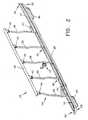
- Fig. 2 is a perspective view illustrating details of the integrated siderail and accessory rail assembly of the present invention;
- Fig. 3 is a sectional view taken along lines 3-3 of Fig. 1 illustrating mounting of the siderail and accessory rail assembly to a frame member of the bed; and
- Fig. 4 is a sectional view taken along lines 4-4 of Fig. 1 illustrating connection of an accessory item to the accessory rail using a suitable clamp.
-
- Referring now to the drawings, Fig. 1 illustrates a
bed 10 having abase 12 and aframe 14 coupled to thebase 12. Adeck 16 is coupled to theframe 14, and apatient support surface 18 is located on thedeck 16. Although a stretcher-type bed 10 is illustrated in Fig. 1, it is understood that any type of bed can be used in accordance with the present invention. Thedeck 16 may be an articulating deck which moves relative to theframe 14 in a conventional manner. - An integrated
rail assembly 20 of the present invention is mounted to opposite sides of thebed 10 to extend parallel to alongitudinal axis 21 of thebed 10. Therail assembly 20 is best illustrated in Fig. 2. Therail assembly 20 includes astraight mounting rail 22 having a length substantially equal to a length of thebed 10. Spaced apartmounting brackets 24 are coupled to themounting rail 22 for securing therail assembly 20 to thebed 10 as discussed in detail below. -
Rail assembly 20 further includes anouter accessory rail 26 for coupling various accessory items to therail assembly 20 as discussed below. Illustratively,rails accessory rail 26 has inwardly bent orcurved end portions 28 which are welded to opposite ends of themounting rail 22 atlocations 30. Therefore, a space orgap 32 is provided between themounting rail 22 and theaccessory rail 26. - A
siderail assembly 34 for thebed 10 is coupled between themounting rail 22 and theaccessory rail 26.Siderail assembly 34 includes atop rail 36 pivotably coupled to top ends ofsiderail tubes 38 bypivot connections 40. Opposite, bottom ends of thetubes 38 are pivotably coupled between themounting rail 22 and theaccessory rail 26 bylower pivot connections 42 as discussed below. Alatch plate 44 is coupled between anend tube 38 and themounting rail 22 andaccessory rail 26 to hold thesiderail assembly 34 in an upright position illustrated in Fig. 2. U-shapeddrain bag holders 46 are coupled to opposite ends of mountingrail 22. Astop 45 is coupled to onetube 38 forengaging frame 14 whensiderail 20 is in the upwardly pivoted in use position of Fig. 2. - Preferably, the
entire rail assembly 20 is coated with a Nylon-based finish to provide a scratch resistant outer surface. After themounting rail 22 and theaccessory rail 26 are welded together, therails base 12 offrame 14 ofbed 10. In addition, the accessory rail may be formed from stainless steel, or made from an injection molded plastic material or other suitable material. - Details of the connection of the
rail assembly 20 to thebed 10 are illustrated in Fig. 3. Themounting brackets 24 are illustratively U-shaped to fit over aframe member 48 ofbed 10. Mountingbrackets 24 are secured to framemember 48 bysuitable fasteners 50.Frame member 48 may be a swing arm pivotably coupled to thebed 10, if desired. Other suitable fasteners such as a clamping device may be used instead ofbrackets 24. - Also as illustrated in Fig. 3, each
tube 38 ofsiderail 34 extends into arotatable bushing 52 which is connected between mountingrail 22 andaccessory rail 26 by asuitable fastener 54.Wave washers 56 are located on opposite sides ofbushing 52. Aspacer block 58 is located betweenbushing 52 andaccessory rail 26. Therefore, siderail 34 can pivot from an upwardly pivoted barrier position shown on one side of thebed 10 in Fig. 1 and in Fig. 2 to a downwardly pivoted, storage position shown an opposite side of thebed 10 in Fig. 1. - After the
rail assembly 20 is coupled to the bed, thesiderails 34 can function in a conventional manner. Theaccessory rail 26 permits accessory items such asitem 60 in Fig. 1 to be mounted to theaccessory rail 26. Illustratively, aclamp 62 is used to secure theaccessory item 60 to theaccessory rail 26.Clamp 62 includes a C-shapedbody 64 for receiving asupport post 66. A threadedactuator 68 is rotatable to secure theclamp 62 to theaccessory rail 26. Illustratively, theaccessory rail 26 may be a 10mm x 25mm rail to accept standard European clamp sizes. - It is understood that any type of accessory item can be coupled to the accessory rail with a similar clamp. It is also understood that accessory items may include hooks or other means for coupling the items directly to the
accessory rail 26 without the need forclamp 62. - Since
accessory rail 26 is integral withsiderail 34, theaccessory rail 26 does not interfere with any moving components of thebed 10 or thesiderail 34. Theintegral rail assembly 20 of the present invention therefore permits theaccessory rail 26 to be used with a anylength siderail 34. As shown in Fig. 1, theaccessory rail 26 extends substantially the entire length ofbed 10. Therefore, theaccessory rail 26 provides a perimeter bumper for the sides ofbed 10. In addition, theaccessory rail 26 does not require any exposed screws or fasteners for mounting. This improves cleanability of theaccessory rail 26. - It is further understood that other types of support mechanisms can be used for the siderail. In certain instances, other pivoting arrangements may be used to secure the siderail to a bottom mounting including the mounting
rail 22 andaccessory rail 26. See, for example, U.S. Patent No. 2,722,017 or 5,129,117.
Claims (13)
- A rail apparatus (20) configured to be mounted to a frame of a bed (10) as a unit, the apparatus comprising an elongated mounting rail (22), at least one mounting bracket (24) for coupling the mounting rail (22) to the frame, an accessory rail (26) coupled to the mounting rail (22) and being configured to receive accessory items, and a siderail (34) pivotally coupled between and supported by the mounting rail (22) and the accessory rail (26).
- The apparatus of claim 1 further comprising a support (38) having a first end pivotally coupled to the siderail (34, 36) and a second end, a bottom mounting (22, 24) pivotally coupled to the second end of the support (38), the bottom mounting including the mounting rail (22) and the at least one mounting bracket (24).
- The apparatus of claim 2 wherein the support includes a plurality of tubes (38), each tube having a first end pivotably coupled to the siderail (34, 36) and a second end pivotably coupled to the bottom mounting (22, 24) so that the siderail is pivotable between an upright barrier position and a collapsed storage position.
- The apparatus of claim 3 wherein the second end of each tube (38) is coupled to a bushing (52), each bushing (52) being pivotably coupled between the mounting rail (22) and the accessory rail (26) by a fastener (54).
- The apparatus of any preceding claim wherein the accessory rail is coupled to the mounting rail at their respective ends.
- The apparatus of claim 5 wherein the accessory rail (26) includes first and second ends (28) which are curved inwardly toward the mounting rail (22).
- The apparatus of claim 6 wherein the first and second curved ends (28) of the accessory rail (26) are welded to the mounting rail (22).
- The apparatus of any preceding claim wherein the accessory rail (26) extends along substantially a full length of a side of the bed (10) to provide a perimeter bumper for the bed.
- The apparatus of any preceding claim wherein the accessory rail (26) has a length which is longer than a length of the siderail (34) so that accessory rail (26) extends beyond the siderail (34) to facilitate mounting of accessory items to the accessory rail.
- The apparatus of any preceding claim wherein the accessory rail (26) extends beyond at least a first end of the siderail (34).
- The apparatus of any preceding claim wherein the accessory rail (26) has a rectangular cross sectional shape.
- The apparatus of any preceding claim wherein the accessory rail (26) is covered with a scratch resistant coating.
- The apparatus of any preceding claim further comprising a drain bag holder (46) coupled to the mounting bracket (24).
Applications Claiming Priority (5)
| Application Number | Priority Date | Filing Date | Title |
|---|---|---|---|
| US735510 | 1996-10-23 | ||
| US08/735,510 US6000076A (en) | 1996-10-23 | 1996-10-23 | Procedural stretcher recline controls |
| US747318 | 1996-11-12 | ||
| US08/747,318 US5802636A (en) | 1996-11-12 | 1996-11-12 | Integrated siderail and accessory rail for a bed |
| EP97911888A EP0971614B1 (en) | 1996-10-23 | 1997-10-20 | Intergrated siderail and accessory rail for a bed |
Related Parent Applications (1)
| Application Number | Title | Priority Date | Filing Date |
|---|---|---|---|
| EP97911888A Division EP0971614B1 (en) | 1996-10-23 | 1997-10-20 | Intergrated siderail and accessory rail for a bed |
Publications (3)
| Publication Number | Publication Date |
|---|---|
| EP1295583A2 true EP1295583A2 (en) | 2003-03-26 |
| EP1295583A3 EP1295583A3 (en) | 2003-10-22 |
| EP1295583B1 EP1295583B1 (en) | 2005-04-20 |
Family
ID=27112899
Family Applications (2)
| Application Number | Title | Priority Date | Filing Date |
|---|---|---|---|
| EP02080558A Expired - Lifetime EP1295583B1 (en) | 1996-10-23 | 1997-10-20 | Integrated siderail and accessory rail for a bed |
| EP97911888A Expired - Lifetime EP0971614B1 (en) | 1996-10-23 | 1997-10-20 | Intergrated siderail and accessory rail for a bed |
Family Applications After (1)
| Application Number | Title | Priority Date | Filing Date |
|---|---|---|---|
| EP97911888A Expired - Lifetime EP0971614B1 (en) | 1996-10-23 | 1997-10-20 | Intergrated siderail and accessory rail for a bed |
Country Status (4)
| Country | Link |
|---|---|
| EP (2) | EP1295583B1 (en) |
| AT (2) | ATE256986T1 (en) |
| DE (2) | DE69727080T2 (en) |
| WO (1) | WO1998017153A1 (en) |
Cited By (3)
| Publication number | Priority date | Publication date | Assignee | Title |
|---|---|---|---|---|
| WO2013140260A3 (en) * | 2012-03-23 | 2014-03-20 | Trumpf Medizin Systeme Gmbh + Co. Kg | Resilient side rails for medical tables |
| US8997281B2 (en) | 2012-03-23 | 2015-04-07 | Trumpf Medizin Systeme Gmbh + Co. Kg | Operating table top assemblies and related devices |
| DE102016201315A1 (en) | 2016-01-29 | 2017-08-03 | Isko Koch Gmbh | care bed |
Families Citing this family (12)
| Publication number | Priority date | Publication date | Assignee | Title |
|---|---|---|---|---|
| US6611979B2 (en) | 1997-09-23 | 2003-09-02 | Hill-Rom Services, Inc. | Mattress having a retractable foot section |
| US6240580B1 (en) * | 1999-03-08 | 2001-06-05 | Hill-Rom, Inc. | Extruded side rail apparatus |
| US6363552B1 (en) | 2000-03-17 | 2002-04-02 | Hill-Rom Services, Inc. | Bed siderail |
| AU2002324763A1 (en) * | 2001-08-22 | 2003-03-10 | Hill-Rom Services, Inc. | Apparatus and method for closing hospital bed gaps |
| AU2003274957B2 (en) | 2002-09-06 | 2009-07-16 | Hill-Rom Services, Inc. | Hospital bed |
| FR2918256B1 (en) | 2007-07-06 | 2009-10-09 | Hill Rom Sas Soc Par Actions S | BED OF SICK WITH SIDE BARRIER REMOVABLE. |
| FR2918551A1 (en) | 2007-07-13 | 2009-01-16 | Hill Rom Sas Soc Par Actions S | EXTENDED LATERAL BARRIER BED |
| FR2921550B1 (en) | 2007-09-28 | 2013-03-29 | Hill Rom Sas | SUSPENDED LATERAL BARRIER BED WHICH MAY CONTAIN MULTIPLE PREDETERMINED POSITIONS |
| US8239986B2 (en) | 2008-03-13 | 2012-08-14 | Hill-Rom Services, Inc. | Siderail assembly for a patient-support apparatus |
| US8646131B2 (en) | 2010-07-30 | 2014-02-11 | Hill-Rom Services, Inc. | Variable height siderail |
| EP2873400B1 (en) | 2013-11-18 | 2018-01-31 | Völker GmbH | Person support apparatus |
| US9463126B2 (en) | 2014-03-11 | 2016-10-11 | Hill-Rom Services, Inc. | Caregiver universal remote cart for patient bed control |
Citations (3)
| Publication number | Priority date | Publication date | Assignee | Title |
|---|---|---|---|---|
| US2722017A (en) | 1951-11-16 | 1955-11-01 | Hill Rom Co Inc | Side guards for hospital beds |
| US5129117A (en) | 1990-11-28 | 1992-07-14 | Hill-Rom Company, Inc. | Birth assist protection guard |
| US5522100A (en) | 1994-05-06 | 1996-06-04 | Stryker Corporation | Stretcher with transfer board which retracts between litter and frame |
Family Cites Families (11)
| Publication number | Priority date | Publication date | Assignee | Title |
|---|---|---|---|---|
| US2976548A (en) * | 1957-11-25 | 1961-03-28 | Gustave R Maertins | Means for mounting a folding side guard on a bed frame |
| US3021534A (en) * | 1958-12-24 | 1962-02-20 | Simmons Co | Adjustable bed rails |
| US3351961A (en) * | 1964-11-27 | 1967-11-14 | William A Daniels | Bedrail |
| GB1094692A (en) * | 1965-05-06 | 1967-12-13 | Llewellyn & Company Ltd F | Improvements in or relating to cot-sides or frames for beds |
| US3956540A (en) * | 1973-09-10 | 1976-05-11 | Omnitech Inc. | Method of coating articles |
| US4651364A (en) * | 1986-05-28 | 1987-03-24 | Simmons Universal Corporation | X-ray cassette holder for a trauma stretcher |
| US4882797A (en) * | 1987-07-15 | 1989-11-28 | Hausted, Inc. | Ophthalmic surgery stretcher |
| US4949410A (en) * | 1988-03-11 | 1990-08-21 | Hausted, Inc. | Guard rail for patient transport apparatus hospital beds and the like |
| US5038430A (en) * | 1990-03-22 | 1991-08-13 | Invacare Corporation | Attaching means for bed cross brace |
| US5407163A (en) * | 1993-11-19 | 1995-04-18 | Hill-Rom Company, Inc. | Sliding IV pole |
| US5499721A (en) * | 1994-07-29 | 1996-03-19 | Schroer Manufacturing Company | Supply stand clamp |
-
1997
- 1997-10-20 AT AT97911888T patent/ATE256986T1/en not_active IP Right Cessation
- 1997-10-20 DE DE69727080T patent/DE69727080T2/en not_active Expired - Lifetime
- 1997-10-20 DE DE69733095T patent/DE69733095T2/en not_active Expired - Lifetime
- 1997-10-20 EP EP02080558A patent/EP1295583B1/en not_active Expired - Lifetime
- 1997-10-20 EP EP97911888A patent/EP0971614B1/en not_active Expired - Lifetime
- 1997-10-20 WO PCT/US1997/019177 patent/WO1998017153A1/en active IP Right Grant
- 1997-10-20 AT AT02080558T patent/ATE293421T1/en not_active IP Right Cessation
Patent Citations (3)
| Publication number | Priority date | Publication date | Assignee | Title |
|---|---|---|---|---|
| US2722017A (en) | 1951-11-16 | 1955-11-01 | Hill Rom Co Inc | Side guards for hospital beds |
| US5129117A (en) | 1990-11-28 | 1992-07-14 | Hill-Rom Company, Inc. | Birth assist protection guard |
| US5522100A (en) | 1994-05-06 | 1996-06-04 | Stryker Corporation | Stretcher with transfer board which retracts between litter and frame |
Cited By (7)
| Publication number | Priority date | Publication date | Assignee | Title |
|---|---|---|---|---|
| WO2013140260A3 (en) * | 2012-03-23 | 2014-03-20 | Trumpf Medizin Systeme Gmbh + Co. Kg | Resilient side rails for medical tables |
| CN104244898A (en) * | 2012-03-23 | 2014-12-24 | 通快医疗系统两合公司 | Resilient side rails for medical tables |
| US8997281B2 (en) | 2012-03-23 | 2015-04-07 | Trumpf Medizin Systeme Gmbh + Co. Kg | Operating table top assemblies and related devices |
| US9289343B2 (en) | 2012-03-23 | 2016-03-22 | Trumpf Medizin Systeme Gmbh + Co. Kg | Resilient side rails for medical tables |
| CN104244898B (en) * | 2012-03-23 | 2016-05-25 | 通快医疗系统两合公司 | For the elasticity siding track of medical work platform |
| DE102016201315A1 (en) | 2016-01-29 | 2017-08-03 | Isko Koch Gmbh | care bed |
| DE102016201315B4 (en) * | 2016-01-29 | 2018-01-18 | Isko Koch Gmbh | care bed |
Also Published As
| Publication number | Publication date |
|---|---|
| ATE293421T1 (en) | 2005-05-15 |
| DE69727080T2 (en) | 2004-06-09 |
| EP0971614A4 (en) | 2000-05-17 |
| EP0971614B1 (en) | 2004-01-02 |
| DE69733095T2 (en) | 2005-09-01 |
| ATE256986T1 (en) | 2004-01-15 |
| EP1295583B1 (en) | 2005-04-20 |
| EP1295583A3 (en) | 2003-10-22 |
| EP0971614A1 (en) | 2000-01-19 |
| DE69727080D1 (en) | 2004-02-05 |
| DE69733095D1 (en) | 2005-05-25 |
| WO1998017153A1 (en) | 1998-04-30 |
Similar Documents
| Publication | Publication Date | Title |
|---|---|---|
| US5802636A (en) | Integrated siderail and accessory rail for a bed | |
| EP1295583B1 (en) | Integrated siderail and accessory rail for a bed | |
| EP0626163B1 (en) | A support mechanism for a bed | |
| US6948202B2 (en) | Accessories for a patient support apparatus | |
| CA2302979C (en) | Adjustable support apparatus | |
| US4700845A (en) | Bicycle storage system | |
| US4886237A (en) | Universal articulatable support for retaining intravenous stands in medical applications | |
| US5526537A (en) | Portable chair commode | |
| US6471167B1 (en) | Surgical tray support system | |
| US5465437A (en) | Bathing appliance for handicapped persons | |
| JP3128240B2 (en) | Hospital bed shielding | |
| US5903935A (en) | Bathing transfer trolley | |
| JP3524104B2 (en) | Hospital room head wall | |
| US5207549A (en) | Transfer seat to be used between a wheelchair and an automobile seat | |
| US5448791A (en) | Support mechanism for a bed | |
| US6305035B1 (en) | Toilet paper holder for bedside commode | |
| US5163968A (en) | Headboard mounting hardware | |
| US4146265A (en) | Catheter bag holder for wheelchairs | |
| EP0554317A1 (en) | Support device. | |
| US20030163871A1 (en) | Frame structure for use with patient support | |
| US6418567B1 (en) | Seating assist apparatus | |
| GB2114880A (en) | Footrest | |
| CN217187407U (en) | Stores pylon is accomodate to drainage tube for surgical nursing | |
| US5823616A (en) | Free-standing booth with tilting table | |
| EP0657155A1 (en) | Accessory attachement system for a bed |
Legal Events
| Date | Code | Title | Description |
|---|---|---|---|
| PUAI | Public reference made under article 153(3) epc to a published international application that has entered the european phase |
Free format text: ORIGINAL CODE: 0009012 |
|
| 17P | Request for examination filed |
Effective date: 20021230 |
|
| AC | Divisional application: reference to earlier application |
Ref document number: 0971614 Country of ref document: EP Kind code of ref document: P |
|
| AK | Designated contracting states |
Designated state(s): AT CH DE FR GB IT LI NL Kind code of ref document: A2 Designated state(s): AT CH DE FR GB IT LI NL |
|
| RIN1 | Information on inventor provided before grant (corrected) |
Inventor name: CORBIN, SCOTT M. Inventor name: MOSTER, JEFFREY A. Inventor name: WEBSTER, THOMAS MATTHEW Inventor name: WALKE, JAMES L. Inventor name: WILSON, ROBERT W. Inventor name: MILLER, JOHN D. Inventor name: HOWELL, CHARLES A. |
|
| PUAL | Search report despatched |
Free format text: ORIGINAL CODE: 0009013 |
|
| AK | Designated contracting states |
Kind code of ref document: A3 Designated state(s): AT CH DE FR GB IT LI NL |
|
| AKX | Designation fees paid |
Designated state(s): AT CH DE FR GB IT LI NL |
|
| GRAP | Despatch of communication of intention to grant a patent |
Free format text: ORIGINAL CODE: EPIDOSNIGR1 |
|
| GRAS | Grant fee paid |
Free format text: ORIGINAL CODE: EPIDOSNIGR3 |
|
| GRAL | Information related to payment of fee for publishing/printing deleted |
Free format text: ORIGINAL CODE: EPIDOSDIGR3 |
|
| GRAS | Grant fee paid |
Free format text: ORIGINAL CODE: EPIDOSNIGR3 |
|
| GRAA | (expected) grant |
Free format text: ORIGINAL CODE: 0009210 |
|
| RAP1 | Party data changed (applicant data changed or rights of an application transferred) |
Owner name: HILL-ROM SERVICES, INC. |
|
| AC | Divisional application: reference to earlier application |
Ref document number: 0971614 Country of ref document: EP Kind code of ref document: P |
|
| AK | Designated contracting states |
Kind code of ref document: B1 Designated state(s): AT CH DE FR GB IT LI NL |
|
| PG25 | Lapsed in a contracting state [announced via postgrant information from national office to epo] |
Ref country code: IT Free format text: LAPSE BECAUSE OF FAILURE TO SUBMIT A TRANSLATION OF THE DESCRIPTION OR TO PAY THE FEE WITHIN THE PRESCRIBED TIME-LIMIT;WARNING: LAPSES OF ITALIAN PATENTS WITH EFFECTIVE DATE BEFORE 2007 MAY HAVE OCCURRED AT ANY TIME BEFORE 2007. THE CORRECT EFFECTIVE DATE MAY BE DIFFERENT FROM THE ONE RECORDED. Effective date: 20050420 Ref country code: LI Free format text: LAPSE BECAUSE OF FAILURE TO SUBMIT A TRANSLATION OF THE DESCRIPTION OR TO PAY THE FEE WITHIN THE PRESCRIBED TIME-LIMIT Effective date: 20050420 Ref country code: CH Free format text: LAPSE BECAUSE OF FAILURE TO SUBMIT A TRANSLATION OF THE DESCRIPTION OR TO PAY THE FEE WITHIN THE PRESCRIBED TIME-LIMIT Effective date: 20050420 Ref country code: NL Free format text: LAPSE BECAUSE OF FAILURE TO SUBMIT A TRANSLATION OF THE DESCRIPTION OR TO PAY THE FEE WITHIN THE PRESCRIBED TIME-LIMIT Effective date: 20050420 Ref country code: AT Free format text: LAPSE BECAUSE OF FAILURE TO SUBMIT A TRANSLATION OF THE DESCRIPTION OR TO PAY THE FEE WITHIN THE PRESCRIBED TIME-LIMIT Effective date: 20050420 |
|
| REG | Reference to a national code |
Ref country code: GB Ref legal event code: FG4D |
|
| REG | Reference to a national code |
Ref country code: CH Ref legal event code: EP |
|
| REF | Corresponds to: |
Ref document number: 69733095 Country of ref document: DE Date of ref document: 20050525 Kind code of ref document: P |
|
| REG | Reference to a national code |
Ref country code: CH Ref legal event code: PL |
|
| NLV1 | Nl: lapsed or annulled due to failure to fulfill the requirements of art. 29p and 29m of the patents act | ||
| PLBE | No opposition filed within time limit |
Free format text: ORIGINAL CODE: 0009261 |
|
| STAA | Information on the status of an ep patent application or granted ep patent |
Free format text: STATUS: NO OPPOSITION FILED WITHIN TIME LIMIT |
|
| ET | Fr: translation filed | ||
| 26N | No opposition filed |
Effective date: 20060123 |
|
| REG | Reference to a national code |
Ref country code: FR Ref legal event code: PLFP Year of fee payment: 20 |
|
| PGFP | Annual fee paid to national office [announced via postgrant information from national office to epo] |
Ref country code: FR Payment date: 20160919 Year of fee payment: 20 |
|
| PGFP | Annual fee paid to national office [announced via postgrant information from national office to epo] |
Ref country code: DE Payment date: 20161011 Year of fee payment: 20 Ref country code: GB Payment date: 20161019 Year of fee payment: 20 |
|
| REG | Reference to a national code |
Ref country code: DE Ref legal event code: R071 Ref document number: 69733095 Country of ref document: DE |
|
| REG | Reference to a national code |
Ref country code: GB Ref legal event code: PE20 Expiry date: 20171019 |
|
| PG25 | Lapsed in a contracting state [announced via postgrant information from national office to epo] |
Ref country code: GB Free format text: LAPSE BECAUSE OF EXPIRATION OF PROTECTION Effective date: 20171019 |