EP1296134B1 - Sampling device and its use for controlling sample introduction in microcolumn separation techniques - Google Patents
Sampling device and its use for controlling sample introduction in microcolumn separation techniques Download PDFInfo
- Publication number
- EP1296134B1 EP1296134B1 EP02028452.7A EP02028452A EP1296134B1 EP 1296134 B1 EP1296134 B1 EP 1296134B1 EP 02028452 A EP02028452 A EP 02028452A EP 1296134 B1 EP1296134 B1 EP 1296134B1
- Authority
- EP
- European Patent Office
- Prior art keywords
- sample
- channel
- electrolyte
- drain
- supply
- Prior art date
- Legal status (The legal status is an assumption and is not a legal conclusion. Google has not performed a legal analysis and makes no representation as to the accuracy of the status listed.)
- Expired - Lifetime
Links
Images
Classifications
-
- C—CHEMISTRY; METALLURGY
- C07—ORGANIC CHEMISTRY
- C07K—PEPTIDES
- C07K1/00—General methods for the preparation of peptides, i.e. processes for the organic chemical preparation of peptides or proteins of any length
- C07K1/14—Extraction; Separation; Purification
- C07K1/24—Extraction; Separation; Purification by electrochemical means
- C07K1/26—Electrophoresis
-
- G—PHYSICS
- G01—MEASURING; TESTING
- G01N—INVESTIGATING OR ANALYSING MATERIALS BY DETERMINING THEIR CHEMICAL OR PHYSICAL PROPERTIES
- G01N27/00—Investigating or analysing materials by the use of electric, electrochemical, or magnetic means
- G01N27/26—Investigating or analysing materials by the use of electric, electrochemical, or magnetic means by investigating electrochemical variables; by using electrolysis or electrophoresis
- G01N27/416—Systems
- G01N27/447—Systems using electrophoresis
- G01N27/44704—Details; Accessories
- G01N27/44743—Introducing samples
-
- G—PHYSICS
- G01—MEASURING; TESTING
- G01N—INVESTIGATING OR ANALYSING MATERIALS BY DETERMINING THEIR CHEMICAL OR PHYSICAL PROPERTIES
- G01N27/00—Investigating or analysing materials by the use of electric, electrochemical, or magnetic means
- G01N27/26—Investigating or analysing materials by the use of electric, electrochemical, or magnetic means by investigating electrochemical variables; by using electrolysis or electrophoresis
- G01N27/416—Systems
- G01N27/447—Systems using electrophoresis
- G01N27/44756—Apparatus specially adapted therefor
- G01N27/44791—Microapparatus
Definitions
- the present invention concerns a sampling device according to patent claim 1 and its use for controlling sample introduction in microcolumn separation techniques.
- Microcolumn separation techniques in particular capillary electrophoresis has become a very interesting separation technique which is used as part of a sensor or a chemical analysis system.
- One major reason for this is the great efficiency of the method as a separation technique.
- the sampling methods usually applied in capillary electrophoresis are:
- sample valves are the most suitable sampling method for capillary electrophoresis
- a valveless device for the injection of a sample comprises a cast capillary block which is connected between an electrode compartment and a sampling device.
- electrolyte solutions contact electrodes.
- the capillary tube contains measuring electrodes which are connected with an evaluation electronics.
- the sampling device consists of a broadened part of the capillary tube connected with two feeders which extend perpendicular to the capillary tube. The arrangement of the two feeders off-set from each other along the longitudinal extension of the capillary-tube is such, that the sampling device has the shape of a capillary double T structure.
- the sample is introduced into the sampling device via a syringe.
- the injection volume is defined geometrically by the distance which the two feeders are spaced apart along the capillary tube.
- the transport of the electrolyte solution and the sample in the capillary tube is accomplished by electric fields that are applied between the respective electrodes along the capillary tube.
- the sample volume shall be geometrically defined.
- the composition of the sample which is injected shall not differ from the original composition of the sample in the reservoir.
- the uncontrolled introduction of sample fluid into the capillary tube shall be reduced considerably. If the unwanted leakage of sample fluid into the capillary tube cannot be totally avoided, provisions shall be made that at least it only occurs in a predictable and controllable manner.
- the method and the sampling device according to the invention shall also allow an easy realization of miniaturized analysis concepts, such as the ones described, for example, in Sensors and Actuators B, 10 (1993) 107-116 .
- miniaturized analysis concepts such as the ones described, for example, in Sensors and Actuators B, 10 (1993) 107-116 .
- a similar concept is described, for example, in Analytical Chemistry , Vol. 64, No. 17, September 1, 1992,1926-1932 .
- the described miniaturized chemical analysis system on the basis of capillary electrophoresis comprises a complex manifold of capillary channels, which are micromachined in a planar glass substrate. The transport of the solvent and the sample occurs due to electro-kinetic effects (electro-osmosis and/or electrophoresis).
- the objects of the invention are met by a device for controlling sample introduction in capillary electrophoresis (CE) according to patent claim 1.
- the sampling device can be used for controlling sample introduction in microcolumn separation techniques, especially in capillary electrophoresis (CE), wherein an electrolyte buffer and a more or less concentrated sample are transported through a system of capillary channels.
- the sample is injected as a sample plug into a sampling device which comprises at least a channel for the sample.
- the channel for the electrolyte buffer and the supply and drain channels for the sample intersect each other.
- the supply channel and the drain channel for the sample each discharge into the channel at respective supply and drain ports.
- the distance between the supply port and the drain port geometrically define a sample volume.
- the supply and the drain channels each are inclined to the electrolyte channel.
- the injection of the sample plug into the electrolyte channel is accomplished electro-kinetically by applying an electric field across the supply and drain channels for a time at least long enough that the sample component having the lowest electrophoretic mobility is contained within the geometrically defined volume. By this measure the composition of the injected sample plug will reflect the actual sample composition.
- the electrolyte buffer is allowed to advance into the supply channel and into the drain channel at the respective supply and drain ports for a time period, which amounts to at least the migration time of a slowest component within the sample plug from the supply port to the detector.
- the sample is pushed back into the respective supply and drain channels and substantially prevented from uncontrollably diffusing into the electrolyte buffer which is transported past the supply and drain ports.
- the method allows to control the sample composition within the electrolyte buffer.
- the sampling device comprises an electrolyte channel, and a supply channel and a drain channel for the sample, which discharge into the electrolyte channel at respective supply and drain ports.
- the ports are arranged with respect to each other such, that a sample volume is geometrically defined.
- the supply and drain channels each are inclined to the electrolyte channel. Means are provided for electro-kinetically injecting a sample into the sample volume.
- the resistance to flow of the source and drain channels with respect to the electrolyte buffer is at least about 5% lower than the respective resistance to flow of the electrolyte channel.
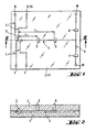
- FIG. 1 and 2 an exemplary embodiment of a microcolumn separation device, more particularly of an electrophoretic separation device, is depicted. It comprises a base part 1 and a lid part 2.
- the base part 1 can be made of glass, monocrystalin silicon or other materials known from semiconductor manufacture, or of a suitable polymer material.
- the lid part 2 is preferably made of glass.
- the base part 1 comprises a channel system 4 which is etched, micromachined or otherwise established in its surface. Preferably techniques known from semiconductor manufacture are applied for creating the channel system in the surface of the base part 1.
- the lid part is provided with through holes R, S, D, W, which communicate with the channel system 4 and are adapted to accomodate and hold the ends of capillary tubes.
- the lid part 2 is also provided with various ports for light waveguides, which are part of an optical detection system, such as, for example, a fluorescence detection system, or an absorption detection system, or a system for the detection of changes of the refractive index of a sample flowing through the channel system.
- the ports are distributed along the channel system 4 after a sampling device 3, where a sample is introduced into an electrolyte buffer, thus allowing measurements at different locations along the channel system.
- the transport of the electrolyte buffer and of the more or less concentrated sample is accomplished by means of electric fields, which are created by switching electric potentials between electrodes of a respective reservoir R and waste receptacles W for the electrolyte buffer and between electrodes associated with respective source S and drain receptacles D for the sample.
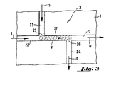
- FIG 3 the encircled sampling device 3 of Figure 1 is shown in an enlarged scale. It is part of the flow injection analysis system of Figure 1 , which is based on electro-kinetic principles and allows an electrophoretic analysis of a sample.
- the sampling device 3 is an integrated part of the capillary channel system 4 and is thus connected with the reservoir R and the waste receptacle W behind the detectors 5-8, for the electrolyte buffer, and with the source receptacle S and the drain receptacle D for the sample which is to be analyzed.
- the reservoir R and the receptacles W, S, D are not drawn, but they are only symbolized by arrows, which at the same time indicate the direction of fluid flow in the channel system 4.
- a first exemplary embodiment of the sampling device comprises a capillary channel piece 22, which on one end is connected to a capillary channel communicating with the reservoir R for the electrolyte buffer and in longitudinal direction on the other end with a capillary channel where the electrophoretic separation of the sample takes place, and which leads to the detector(s) and in further consequence to the waste receptacle(s) W.
- the sampling device further comprises a supply channel 23, which communicates with a source receptacle S for the sample, and a drain channel 24 which leads to a drain receptacle D.
- the source channel 23 and the drain channel 24 are inclined to the longitudinal extension of the channel piece 2, they are arranged about perpendicular such, that together with the channel piece 22 they form a double T structure, as shown in the drawing.
- the source channel S and the drain channel D each discharge into the channel piece 22 at respective supply and drain ports 25, 26.
- the supply port 25 and the drain port 26 are spaced apart from each other longitudinally at the channel piece 22 such, that a sample volume 27 is geometrically defined as will be explained in more detail hereinafter.
- the distance which they are spaced apart from each other typically amounts to from about 3 ⁇ m to about 3 cm, most preferably to about 3 mm.
- the transport of the fluids i.e. the electrolyte buffer and the sample
- electric fields which are a result of different electric potentials at the reservoir R and the waste receptacle W for the electrolyte buffer, and the respective source receptacle S and the drain receptacle D for the sample.
- the electrolyte buffer is electro-kinetically transported from the reservoir R through the capillary channel system to the waste receptacle W.
- the source receptacle In order to introduce the sample into the channel piece 22, for example, the source receptacle.
- the sample-filled part 27 of the channel piece of the sampling device 3 defines the volume of the electro-kinetically injected sample plug, which is indicated by the hatchings in Figure 3 .
- the volume 27 of the sample plug is geometrically delimited by the spaced apart supply and drain ports 25 and 26.
- an electric field between the reservoir R and the waste receptacle W is established such, that the electrolyte buffer is transported from the reservoir R to the waste receptacle W.
- the injection of the sample into the channel piece 22 is initiated.
- an electric field is established between the source receptacle S and the drain receptacle D such, that the sample is electro-kinetically transported from the source receptacle S through the supply channel 23 via the channel piece 22 into the drain channel 24 and on to the drain receptacle D.
- the electric field between the reservoir R and the waste receptacle W is switched off, or that the potentials are chosen such, that the sample only is transported along the path described above.
- the electric field between the source receptacle S and the drain receptacle D is switched off.
- the electric field between the reservoir R and the waste receptacle W is activated again such, that the sample contained within the sample volume 27 is transported on into the direction of the detector(s) and the waste reservoir. While it is transported through the channel system the sample is separated electrophoretically in the electric field.
- the problem of leakage or diffusion of sample components into the electrolyte buffer while it is transported past the supply and drain ports 23 and 24, even though no electric field is applied between the source receptacle S and the drain receptacle D, is solved by allowing the electrolyte buffer to advance into the supply channel 23 and into the drain channel 24 at the respective supply and drain ports 25 and 26 for a time period, which amounts to at least the migration time t i of the slowest component i within the sample plug from the supply port 25 to the respective detector.
- the sample is pushed back into the supply and drain channels 23, 24 and substantially prevented from uncontrollably diffusing into the electrolyte buffer which is transported past the supply and drain ports 25, 26.
- the separation length L Fig. 1
- the total mobility ⁇ i of the component is the sum of the electrophoretic mobility ⁇ i,ep of the component and the overall electro-osmotic mobility. ⁇ eo of the sample.
- the time period during which' the detection is accomplished is very short in comparison to the migration time of the slowest component of the sample and thus is neglectable.
- the source receptacle S and the drain receptacle D are switched on an electric potential which is different from the electric potential at the reservoir R for the electrolyte buffer, thus establishing a potential difference of suitable magnitude.
- the potentials at the source and drain receptacles S, D are chosen negative with respect to the positive potential at the reservoir R.
- the potentials of the source and drain receptacles S, D are chosen positive with respect to the reservoir R.
- the potential difference between the reservoir R and the source and drain receptacles S, D is chosen such, that the resultant electric field has a field strength which amounts to at least about 0.1 V/cm.
- the sampling device 3 has been explained with reference to exemplary embodiments which are part of micro-analysis chips. It can as well be an arrangement of capillary tubes, which is part of a electrophoretic chemical analysis system made of capillary tubes.
- the sampling device is integrated into a system of capillary channels which may be established in a small planar sheet of glass, semiconductor material, or a suitable polymer.
- the channel system including the supply and drain channels and the respective supply and drain ports are etched or micromachined or casted (in case of a polymer base part), or otherwise established in the planar substrate.
- Most suitable for its manufacture are techniques which are well established in semiconductor production or in the manufacture of micromechanical elements.
- the combination of a structure that geometrically defines the injected sample volume with an electro-kinetic injection of the sample over a defined minimum time period allows to relyably control the sample volume and to assure that the composition of the sample contained within the sample volume reflects the original composition of the sample in the reservoir.
- a further improvement of the method and the sampling device according to the invention allows a considerable reduction of uncontrolled leakage or diffusion of sample components into the electrolyte buffer.
- the noise of the detected electrophoretic signal is reduced and the detection limits are increased.
Description
- The present invention concerns a sampling device according to
patent claim 1 and its use for controlling sample introduction in microcolumn separation techniques. - Microcolumn separation techniques, in particular capillary electrophoresis has become a very interesting separation technique which is used as part of a sensor or a chemical analysis system. One major reason for this is the great efficiency of the method as a separation technique. The sampling methods usually applied in capillary electrophoresis are:
- injection of a sample with a syringe, via a septum, in an injection block, the use of injection valves with/without a sample loop, and
- dipping one end of the capillary tube into the sample reservoir, whereby the sample is introduced by gravity flow, by over- or underpressure, or by electroendosmosis and/or electromigration.
- While it is mentioned in Journal of Chromatography, 452, (1988) 615-622, that sample valves are the most suitable sampling method for capillary electrophoresis, there also is described a valveless device for the injection of a sample. The described arrangement comprises a cast capillary block which is connected between an electrode compartment and a sampling device. In the electrode compartment electrolyte solutions contact electrodes. The capillary tube contains measuring electrodes which are connected with an evaluation electronics. The sampling device consists of a broadened part of the capillary tube connected with two feeders which extend perpendicular to the capillary tube. The arrangement of the two feeders off-set from each other along the longitudinal extension of the capillary-tube is such, that the sampling device has the shape of a capillary double T structure.
- The sample is introduced into the sampling device via a syringe. The injection volume is defined geometrically by the distance which the two feeders are spaced apart along the capillary tube. The transport of the electrolyte solution and the sample in the capillary tube is accomplished by electric fields that are applied between the respective electrodes along the capillary tube. An advantage of the double T shape sampling device, as is also obtained with the use of injection valves, is the concentration effect of dilute sample ionic species. However, it is possible that, although no electric field gradient over the feeders exists, sample components from the feeders may diffuse into the capillary tube when the sample has already left the sampling position. The amounts of sample components that uncontrollably enter the capillary tube depend on the diffusion coefficients and the mobilities of the respective sample components. Thus, at the detector there not only arrives a more or less broadened plug of injected sample fluid, depending on the diffusion coefficients and the mobilities of the respective components in the electrolyte and the electric field, but also the electrolyte in front and after or between individual plugs of sample fluid is "polluted" with unpredictable amounts of sample components. These unpredictable amounts of sample components reaching the detector are highly undesirable and result in a high noise of the detected signal, thus reducing the limits of detection considerably.
- In Analytical Chemistry, 1992, 64, pages 1926 -1932 a capillary electrophoretic device is described in which the sample is injected electrokinetically dipping one end of a capillary into the sample reservoir and applying a voltage across the ends of the capillary. In the electric field the sample is transported electrokinetically and is injected at a T-junction into the channel system of the capillary electrophoretic device. This method, however, leads to a well-known bias of the actual sample composition due to the differences in the electrophoretic mobilities of the sample components. Thus, the sample introduced often does not have the same composition as the original sample. In addition; the volume of the introduced sample is very often unknown such, that internal standards have to be used for quantitative analyses.
- It is therefore an object of the present invention to provide a sampling device for controlling sample introduction in microcolumn separation techniques, and more particularly in capillary electrophoresis (CE), which overcomes the aforementioned disadvantages of the prior art. The sample volume shall be geometrically defined. The composition of the sample which is injected shall not differ from the original composition of the sample in the reservoir. The uncontrolled introduction of sample fluid into the capillary tube shall be reduced considerably. If the unwanted leakage of sample fluid into the capillary tube cannot be totally avoided, provisions shall be made that at least it only occurs in a predictable and controllable manner.
- The method and the sampling device according to the invention shall also allow an easy realization of miniaturized analysis concepts, such as the ones described, for example, in Sensors and Actuators B, 10 (1993) 107-116. There the concept of a multi-manifold flow system integrated on a silicon substrate, with valveless switching of solvent flow between channels and electro-kinetic pumping of an aqueous solvent, is described. A similar concept is described, for example, in Analytical Chemistry , Vol. 64, No. 17, September 1, 1992,1926-1932. The described miniaturized chemical analysis system on the basis of capillary electrophoresis comprises a complex manifold of capillary channels, which are micromachined in a planar glass substrate. The transport of the solvent and the sample occurs due to electro-kinetic effects (electro-osmosis and/or electrophoresis).
- The objects of the invention are met by a device for controlling sample introduction in capillary electrophoresis (CE) according to
patent claim 1. The sampling device can be used for controlling sample introduction in microcolumn separation techniques, especially in capillary electrophoresis (CE), wherein an electrolyte buffer and a more or less concentrated sample are transported through a system of capillary channels. The sample is injected as a sample plug into a sampling device which comprises at least a channel for the sample. The channel for the electrolyte buffer and the supply and drain channels for the sample intersect each other. The supply channel and the drain channel for the sample, each discharge into the channel at respective supply and drain ports. The distance between the supply port and the drain port geometrically define a sample volume. The supply and the drain channels each are inclined to the electrolyte channel. The injection of the sample plug into the electrolyte channel is accomplished electro-kinetically by applying an electric field across the supply and drain channels for a time at least long enough that the sample component having the lowest electrophoretic mobility is contained within the geometrically defined volume. By this measure the composition of the injected sample plug will reflect the actual sample composition. - In a further preferred process step, immediately after the injection of the sample plug, the electrolyte buffer is allowed to advance into the supply channel and into the drain channel at the respective supply and drain ports for a time period, which amounts to at least the migration time of a slowest component within the sample plug from the supply port to the detector. Thus, the sample is pushed back into the respective supply and drain channels and substantially prevented from uncontrollably diffusing into the electrolyte buffer which is transported past the supply and drain ports. In addition, the method allows to control the sample composition within the electrolyte buffer.
- The objects with respect to the improvements of the sampling device are met by a sampling device according to the characterizing part of
patent claim 1. In particular, the sampling device comprises an electrolyte channel, and a supply channel and a drain channel for the sample, which discharge into the electrolyte channel at respective supply and drain ports. The ports are arranged with respect to each other such, that a sample volume is geometrically defined. The supply and drain channels each are inclined to the electrolyte channel. Means are provided for electro-kinetically injecting a sample into the sample volume. - The resistance to flow of the source and drain channels with respect to the electrolyte buffer is at least about 5% lower than the respective resistance to flow of the electrolyte channel.
- Preferred variants of the method according to the invention and preferred embodiments of the sampling device according to the invention are subject of the respective dependent claims. The invention will become apparent from the following description with reference to the schematic drawings in which:
-
Fig. 1 is a schematic view of a microcolumn separation device which comprises a sampling device according to the present invention, -
Fig. 2 is a sectional view of the microcolumn separation device according toFigure 1 , and -
Fig. 3 is an enlarged view of the encircled pan of the microcolumn separation device according toFigure 1 , showing an embodiment of a sampling device. - In
Figures 1 and 2 an exemplary embodiment of a microcolumn separation device, more particularly of an electrophoretic separation device, is depicted. It comprises abase part 1 and alid part 2. Thebase part 1 can be made of glass, monocrystalin silicon or other materials known from semiconductor manufacture, or of a suitable polymer material. Thelid part 2 is preferably made of glass. Thebase part 1 comprises a channel system 4 which is etched, micromachined or otherwise established in its surface. Preferably techniques known from semiconductor manufacture are applied for creating the channel system in the surface of thebase part 1. The lid part is provided with through holes R, S, D, W, which communicate with the channel system 4 and are adapted to accomodate and hold the ends of capillary tubes. Thelid part 2 is also provided with various ports for light waveguides, which are part of an optical detection system, such as, for example, a fluorescence detection system, or an absorption detection system, or a system for the detection of changes of the refractive index of a sample flowing through the channel system. The ports are distributed along the channel system 4 after asampling device 3, where a sample is introduced into an electrolyte buffer, thus allowing measurements at different locations along the channel system. - The transport of the electrolyte buffer and of the more or less concentrated sample is accomplished by means of electric fields, which are created by switching electric potentials between electrodes of a respective reservoir R and waste receptacles W for the electrolyte buffer and between electrodes associated with respective source S and drain receptacles D for the sample.
- In
Figure 3 the encircledsampling device 3 ofFigure 1 is shown in an enlarged scale. It is part of the flow injection analysis system ofFigure 1 , which is based on electro-kinetic principles and allows an electrophoretic analysis of a sample. Thesampling device 3 is an integrated part of the capillary channel system 4 and is thus connected with the reservoir R and the waste receptacle W behind the detectors 5-8, for the electrolyte buffer, and with the source receptacle S and the drain receptacle D for the sample which is to be analyzed. InFigure 3 , for the sake of clarity, the reservoir R and the receptacles W, S, D are not drawn, but they are only symbolized by arrows, which at the same time indicate the direction of fluid flow in the channel system 4. - In
Figure 3 a first exemplary embodiment of the sampling device is shown. It comprises acapillary channel piece 22, which on one end is connected to a capillary channel communicating with the reservoir R for the electrolyte buffer and in longitudinal direction on the other end with a capillary channel where the electrophoretic separation of the sample takes place, and which leads to the detector(s) and in further consequence to the waste receptacle(s) W. The sampling device further comprises asupply channel 23, which communicates with a source receptacle S for the sample, and adrain channel 24 which leads to a drain receptacle D. Thesource channel 23 and thedrain channel 24 are inclined to the longitudinal extension of thechannel piece 2, they are arranged about perpendicular such, that together with thechannel piece 22 they form a double T structure, as shown in the drawing. The source channel S and the drain channel D each discharge into thechannel piece 22 at respective supply anddrain ports Figure 3 thesupply port 25 and thedrain port 26 are spaced apart from each other longitudinally at thechannel piece 22 such, that asample volume 27 is geometrically defined as will be explained in more detail hereinafter. The distance which they are spaced apart from each other typically amounts to from about 3 µm to about 3 cm, most preferably to about 3 mm. - As already mentioned before the transport of the fluids, i.e. the electrolyte buffer and the sample, is accomplished with electric fields, which are a result of different electric potentials at the reservoir R and the waste receptacle W for the electrolyte buffer, and the respective source receptacle S and the drain receptacle D for the sample. By applying, for example, a positive electric potential to the reservoir R and a negative electric potential to the waste receptacle, the electrolyte buffer is electro-kinetically transported from the reservoir R through the capillary channel system to the waste receptacle W. In order to introduce the sample into the
channel piece 22, for example, the source receptacle. S for the sample is maintained at a positive potential and the drain receptacle D is kept on a negative potential. In the resulting electric field the sample is transported electro-kinetically from the source receptacle S to the drain receptacle D. The direction of flow is indicated inFigure 3 by the arrows S, V, and D. By this measure, apart 27 of thechannel piece 22, which is delimited by thesupply port 25 on the one end and by thedrain port 26 on the other end is filled with sample. Thus, the sample-filledpart 27 of the channel piece of thesampling device 3 defines the volume of the electro-kinetically injected sample plug, which is indicated by the hatchings inFigure 3 . In other words, thevolume 27 of the sample plug is geometrically delimited by the spaced apart supply anddrain ports - In order to assure that the composition of the sample in the
sample volume 27 reflects the actual sample composition in the reservoir R the electric field across the supply anddrain channels - When a electrophoretic analysis of a sample is to be carried out, first an electric field between the reservoir R and the waste receptacle W is established such, that the electrolyte buffer is transported from the reservoir R to the waste receptacle W. After the channel system of the chemical analysis system has been filled with the electrolyte buffer, the injection of the sample into the
channel piece 22 is initiated. For that purpose, an electric field is established between the source receptacle S and the drain receptacle D such, that the sample is electro-kinetically transported from the source receptacle S through thesupply channel 23 via thechannel piece 22 into thedrain channel 24 and on to the drain receptacle D. It is understood that during the time period, in which the sample is injected, the electric field between the reservoir R and the waste receptacle W is switched off, or that the potentials are chosen such, that the sample only is transported along the path described above. After the injection time period which is chosen such, that it is ensured that thesample volume 27 between thesupply port 25 and thedrain port 26 is filled with the sample, the electric field between the source receptacle S and the drain receptacle D is switched off. At the same time the electric field between the reservoir R and the waste receptacle W is activated again such, that the sample contained within thesample volume 27 is transported on into the direction of the detector(s) and the waste reservoir. While it is transported through the channel system the sample is separated electrophoretically in the electric field. - The problem of leakage or diffusion of sample components into the electrolyte buffer while it is transported past the supply and
drain ports supply channel 23 and into thedrain channel 24 at the respective supply anddrain ports supply port 25 to the respective detector. Thus, the sample is pushed back into the supply anddrain channels drain ports - The migration time ti of the slowest component i of the sample is defined as the quotient between the separation length L and the product of the total mobility µi of the slowest component i of the sample and the electric field strength E' acting on it along its path L, and is given by the equation Ti = L/µi E'). In this equation the separation length L (
Fig. 1 ) is the distance the sample component i travels between thesupply port 25 and the respective activated detector 5-8, and the total mobility µi of the component is the sum of the electrophoretic mobility µi,ep of the component and the overall electro-osmotic mobility. µeo of the sample. The time period during which' the detection is accomplished is very short in comparison to the migration time of the slowest component of the sample and thus is neglectable. - In order to allow the electrolyte buffer to advance into the supply and
drain channels Fig. 3 the source receptacle S and the drain receptacle D are switched on an electric potential which is different from the electric potential at the reservoir R for the electrolyte buffer, thus establishing a potential difference of suitable magnitude. In an embodiment, where the electrolyte buffer is transported from a positive potential to a negative potential, the potentials at the source and drain receptacles S, D are chosen negative with respect to the positive potential at the reservoir R. In case of a transport of the electrolyte buffer from a negative potential to a positive potential the potentials of the source and drain receptacles S, D are chosen positive with respect to the reservoir R. - Preferably the potential difference between the reservoir R and the source and drain receptacles S, D is chosen such, that the resultant electric field has a field strength which amounts to at least about 0.1 V/cm.
- The
sampling device 3 according to the invention has been explained with reference to exemplary embodiments which are part of micro-analysis chips. It can as well be an arrangement of capillary tubes, which is part of a electrophoretic chemical analysis system made of capillary tubes. The sampling device is integrated into a system of capillary channels which may be established in a small planar sheet of glass, semiconductor material, or a suitable polymer. Advantageously the channel system including the supply and drain channels and the respective supply and drain ports are etched or micromachined or casted (in case of a polymer base part), or otherwise established in the planar substrate. Most suitable for its manufacture are techniques which are well established in semiconductor production or in the manufacture of micromechanical elements. - The combination of a structure that geometrically defines the injected sample volume with an electro-kinetic injection of the sample over a defined minimum time period allows to relyably control the sample volume and to assure that the composition of the sample contained within the sample volume reflects the original composition of the sample in the reservoir. A further improvement of the method and the sampling device according to the invention allows a considerable reduction of uncontrolled leakage or diffusion of sample components into the electrolyte buffer. Thus, it is possible to reduce the leakage or diffusion such, that the still occuring leakage results in a concentration of the sample in the electrolyte buffer, that is less than 3% of the original concentration of the sample. By this measure the noise of the detected electrophoretic signal is reduced and the detection limits are increased.
Claims (5)
- A sampling device comprising capillary electrolyte channel (22) for an electrolyte buffer connected to a reservoir for electrolyte buffer (R) and a waste receptacle (W), a capillary supply channel (23) and opposite thereto a capillary drain channel (24) for a sample, wherein said supply and drain channels each are about perpendicular to the longitudinal extension of said electrolyte channel (22), and which supply and drain channels each discharge into said electrolyte channel (22) at supply (25) and drain ports (26) in a double T structure, respectively, such that a sample volume (27) is defined by a section of said electrolyte channel located between said supply port and drain port, which sampling device further comprises means for electrokinetically injectin a sample in said geometrically defined sample volume by applying an electric field between electrodes associated with respective source (S) and drain (D) receptacles, said supply (25) and drain ports (26) are spaced apart from each other longitudinally along the electrolyte channel and form said sample volume (27), and wherein electrolyte channel (22) for an electrolyte buffer is connected to a reservoir for electrolyte buffer (R) and a waste receptacle each comprising electrodes for electrokinetically injecting electrolyte buffer into electrolyte channel (22).
- A sampling device according to claim 1, wherein said channels have a depth of from 0.1 µm to 100 µm.
- A sampling device according to claim 1, wherein said supply (25) and drain ports (26) are spaced apart from each other a distance which amounts to from 3 mm to 3 cm, preferably 3 mm.
- A sampling device according to claim 1, comprising a system of capillary channels with an electrolyte channel (22) for an electrolyte buffer, a supply (23) and a drain channel (24) and wherein the electrolyte channel is connected at one end to a reservoir for the electrolyte buffer and extends after said geometrically defined sample volume in longitudinal direction in a capillary channel.
- Use of a sampling device according to claim 1 for electrokinetic sample introduction and capillary electrophoretic separation.
Priority Applications (1)
| Application Number | Priority Date | Filing Date | Title |
|---|---|---|---|
| EP02028452.7A EP1296134B1 (en) | 1993-04-15 | 1993-04-15 | Sampling device and its use for controlling sample introduction in microcolumn separation techniques |
Applications Claiming Priority (2)
| Application Number | Priority Date | Filing Date | Title |
|---|---|---|---|
| EP02028452.7A EP1296134B1 (en) | 1993-04-15 | 1993-04-15 | Sampling device and its use for controlling sample introduction in microcolumn separation techniques |
| EP93810272A EP0620432B1 (en) | 1993-04-15 | 1993-04-15 | Method for controlling sample introduction in microcolumn separation techniques and sampling device |
Related Parent Applications (2)
| Application Number | Title | Priority Date | Filing Date |
|---|---|---|---|
| EP93810272A Division EP0620432B1 (en) | 1993-04-15 | 1993-04-15 | Method for controlling sample introduction in microcolumn separation techniques and sampling device |
| EP93810272.0 Division | 1993-04-15 |
Publications (3)
| Publication Number | Publication Date |
|---|---|
| EP1296134A2 EP1296134A2 (en) | 2003-03-26 |
| EP1296134A3 EP1296134A3 (en) | 2003-12-03 |
| EP1296134B1 true EP1296134B1 (en) | 2013-05-29 |
Family
ID=8214951
Family Applications (2)
| Application Number | Title | Priority Date | Filing Date |
|---|---|---|---|
| EP93810272A Expired - Lifetime EP0620432B1 (en) | 1993-04-15 | 1993-04-15 | Method for controlling sample introduction in microcolumn separation techniques and sampling device |
| EP02028452.7A Expired - Lifetime EP1296134B1 (en) | 1993-04-15 | 1993-04-15 | Sampling device and its use for controlling sample introduction in microcolumn separation techniques |
Family Applications Before (1)
| Application Number | Title | Priority Date | Filing Date |
|---|---|---|---|
| EP93810272A Expired - Lifetime EP0620432B1 (en) | 1993-04-15 | 1993-04-15 | Method for controlling sample introduction in microcolumn separation techniques and sampling device |
Country Status (4)
| Country | Link |
|---|---|
| US (10) | US6280589B1 (en) |
| EP (2) | EP0620432B1 (en) |
| JP (1) | JP3656165B2 (en) |
| DE (1) | DE69333601T2 (en) |
Families Citing this family (158)
| Publication number | Priority date | Publication date | Assignee | Title |
|---|---|---|---|---|
| US6176962B1 (en) | 1990-02-28 | 2001-01-23 | Aclara Biosciences, Inc. | Methods for fabricating enclosed microchannel structures |
| EP0620432B1 (en) * | 1993-04-15 | 2004-08-25 | Zeptosens AG | Method for controlling sample introduction in microcolumn separation techniques and sampling device |
| US6001229A (en) * | 1994-08-01 | 1999-12-14 | Lockheed Martin Energy Systems, Inc. | Apparatus and method for performing microfluidic manipulations for chemical analysis |
| US5630924A (en) | 1995-04-20 | 1997-05-20 | Perseptive Biosystems, Inc. | Compositions, methods and apparatus for ultrafast electroseparation analysis |
| EP0909385B1 (en) * | 1996-06-28 | 2008-09-10 | Caliper Life Sciences, Inc. | Method of transporting fluid samples within a microfluidic channel |
| US6110343A (en) * | 1996-10-04 | 2000-08-29 | Lockheed Martin Energy Research Corporation | Material transport method and apparatus |
| US6447727B1 (en) * | 1996-11-19 | 2002-09-10 | Caliper Technologies Corp. | Microfluidic systems |
| US5954931A (en) * | 1997-01-24 | 1999-09-21 | Motorola, Inc. | Electrophoresis apparatus and method involving parallel channels |
| US6056859A (en) * | 1997-02-12 | 2000-05-02 | Lockheed Martin Energy Research Corporation | Method and apparatus for staining immobilized nucleic acids |
| CA2284612A1 (en) * | 1997-04-04 | 1998-10-15 | Michael Knapp | Closed-loop biochemical analyzers |
| WO1998049548A1 (en) * | 1997-04-25 | 1998-11-05 | Caliper Technologies Corporation | Microfluidic devices incorporating improved channel geometries |
| AU747505B2 (en) * | 1997-04-25 | 2002-05-16 | Caliper Life Sciences, Inc. | Microfluidic devices incorporating improved channel geometries |
| US5976336A (en) * | 1997-04-25 | 1999-11-02 | Caliper Technologies Corp. | Microfluidic devices incorporating improved channel geometries |
| WO1998049344A1 (en) | 1997-04-28 | 1998-11-05 | Lockheed Martin Energy Research Corporation | Method and apparatus for analyzing nucleic acids |
| US6090251A (en) | 1997-06-06 | 2000-07-18 | Caliper Technologies, Inc. | Microfabricated structures for facilitating fluid introduction into microfluidic devices |
| US5900130A (en) * | 1997-06-18 | 1999-05-04 | Alcara Biosciences, Inc. | Method for sample injection in microchannel device |
| US6685809B1 (en) | 1999-02-04 | 2004-02-03 | Ut-Battelle, Llc | Methods for forming small-volume electrical contacts and material manipulations with fluidic microchannels |
| DE19815882A1 (en) * | 1998-04-08 | 1999-10-14 | Fuhr Guenther | Method and device for manipulating microparticles in fluid flows |
| US6306590B1 (en) * | 1998-06-08 | 2001-10-23 | Caliper Technologies Corp. | Microfluidic matrix localization apparatus and methods |
| JP3866517B2 (en) * | 1998-08-06 | 2007-01-10 | 株式会社日立製作所 | Sample introduction apparatus, ion source using the same, and mass spectrometer |
| AU5448299A (en) * | 1998-09-02 | 2000-03-27 | Sankyo Company Limited | Electrophoresis system |
| US6062261A (en) * | 1998-12-16 | 2000-05-16 | Lockheed Martin Energy Research Corporation | MicrofluIdic circuit designs for performing electrokinetic manipulations that reduce the number of voltage sources and fluid reservoirs |
| CA2371767C (en) * | 1999-02-18 | 2007-05-08 | Toyo Kohan Co., Ltd. | Micro-chip for chemical reaction |
| ATE508200T1 (en) | 1999-02-23 | 2011-05-15 | Caliper Life Sciences Inc | SEQUENCING THROUGH INCORPORATION |
| US6322683B1 (en) * | 1999-04-14 | 2001-11-27 | Caliper Technologies Corp. | Alignment of multicomponent microfabricated structures |
| US6270641B1 (en) * | 1999-04-26 | 2001-08-07 | Sandia Corporation | Method and apparatus for reducing sample dispersion in turns and junctions of microchannel systems |
| DE19949538C2 (en) * | 1999-10-14 | 2001-08-23 | Karlsruhe Forschzent | Microcapillary and process for its manufacture |
| CA2290731A1 (en) * | 1999-11-26 | 2001-05-26 | D. Jed Harrison | Apparatus and method for trapping bead based reagents within microfluidic analysis system |
| US6432290B1 (en) | 1999-11-26 | 2002-08-13 | The Governors Of The University Of Alberta | Apparatus and method for trapping bead based reagents within microfluidic analysis systems |
| WO2001051918A1 (en) | 2000-01-12 | 2001-07-19 | Ut-Battelle, Llc | A microfluidic device and method for focusing, segmenting, and dispensing of a fluid stream |
| DE60140111D1 (en) * | 2000-02-11 | 2009-11-19 | Aclara Biosciences Inc | MICROFLUIDIC DEVICE WITH A LIQUID SAMPLE INJECTION DEVICE AND USE METHOD |
| US6685813B2 (en) | 2000-02-11 | 2004-02-03 | Aclara Biosciences, Inc. | Tandem isotachophoresis/zone electrophoresis method and system |
| US20040108207A1 (en) * | 2000-02-11 | 2004-06-10 | Aclara Biosciences, Inc. | Injection and separation system and method employing transient isotachophoretic stacking |
| WO2001061335A2 (en) * | 2000-02-17 | 2001-08-23 | Evotec Oai Ag | Method and device for bias-free electrokinetic sample introduction and separation |
| US6733645B1 (en) | 2000-04-18 | 2004-05-11 | Caliper Technologies Corp. | Total analyte quantitation |
| DE10041853C1 (en) * | 2000-08-25 | 2002-02-28 | Gmd Gmbh | Configurable microreactor network |
| EP2299256A3 (en) * | 2000-09-15 | 2012-10-10 | California Institute Of Technology | Microfabricated crossflow devices and methods |
| US6939451B2 (en) | 2000-09-19 | 2005-09-06 | Aclara Biosciences, Inc. | Microfluidic chip having integrated electrodes |
| US20020112959A1 (en) * | 2000-10-04 | 2002-08-22 | Qifeng Xue | Unbiased sample injection for microfluidic applications |
| US20030057092A1 (en) * | 2000-10-31 | 2003-03-27 | Caliper Technologies Corp. | Microfluidic methods, devices and systems for in situ material concentration |
| US20050011761A1 (en) * | 2000-10-31 | 2005-01-20 | Caliper Technologies Corp. | Microfluidic methods, devices and systems for in situ material concentration |
| WO2002060754A1 (en) * | 2001-01-29 | 2002-08-08 | Caliper Technologies Corp. | Non-mechanical valves for fluidic systems |
| US20020168780A1 (en) * | 2001-02-09 | 2002-11-14 | Shaorong Liu | Method and apparatus for sample injection in microfabricated devices |
| AU2002256998A1 (en) * | 2001-02-09 | 2002-09-19 | Microchem Solutions | Apparatus and method for small-volume fluid manipulation and transportation |
| US20020180963A1 (en) * | 2001-02-15 | 2002-12-05 | Caliper Technologies Corp. | Microfluidic systems with enhanced detection systems |
| US7670559B2 (en) * | 2001-02-15 | 2010-03-02 | Caliper Life Sciences, Inc. | Microfluidic systems with enhanced detection systems |
| US7867776B2 (en) * | 2001-03-02 | 2011-01-11 | Caliper Life Sciences, Inc. | Priming module for microfluidic chips |
| US7150999B1 (en) | 2001-03-09 | 2006-12-19 | Califer Life Sciences, Inc. | Process for filling microfluidic channels |
| US7723123B1 (en) | 2001-06-05 | 2010-05-25 | Caliper Life Sciences, Inc. | Western blot by incorporating an affinity purification zone |
| US20020187564A1 (en) * | 2001-06-08 | 2002-12-12 | Caliper Technologies Corp. | Microfluidic library analysis |
| JP4841063B2 (en) * | 2001-06-12 | 2011-12-21 | テクノクオーツ株式会社 | Microchannel structure and manufacturing method thereof |
| US6977163B1 (en) | 2001-06-13 | 2005-12-20 | Caliper Life Sciences, Inc. | Methods and systems for performing multiple reactions by interfacial mixing |
| US20030027225A1 (en) * | 2001-07-13 | 2003-02-06 | Caliper Technologies Corp. | Microfluidic devices and systems for separating components of a mixture |
| US7060171B1 (en) | 2001-07-31 | 2006-06-13 | Caliper Life Sciences, Inc. | Methods and systems for reducing background signal in assays |
| US6803568B2 (en) * | 2001-09-19 | 2004-10-12 | Predicant Biosciences, Inc. | Multi-channel microfluidic chip for electrospray ionization |
| US20050150766A1 (en) * | 2001-11-02 | 2005-07-14 | Andreas Manz | Capillary electrophoresis microchip system and method |
| US7247274B1 (en) | 2001-11-13 | 2007-07-24 | Caliper Technologies Corp. | Prevention of precipitate blockage in microfluidic channels |
| US7105810B2 (en) * | 2001-12-21 | 2006-09-12 | Cornell Research Foundation, Inc. | Electrospray emitter for microfluidic channel |
| JP4417116B2 (en) * | 2002-03-05 | 2010-02-17 | カリパー・ライフ・サイエンシズ・インク. | Mixed microfluidic system |
| WO2003084629A2 (en) * | 2002-04-02 | 2003-10-16 | Caliper Life Sciences, Inc. | Methods and apparatus for separation and isolation of components from a biological sample |
| US20030217923A1 (en) * | 2002-05-24 | 2003-11-27 | Harrison D. Jed | Apparatus and method for trapping bead based reagents within microfluidic analysis systems |
| US7161356B1 (en) | 2002-06-05 | 2007-01-09 | Caliper Life Sciences, Inc. | Voltage/current testing equipment for microfluidic devices |
| US20050238506A1 (en) * | 2002-06-21 | 2005-10-27 | The Charles Stark Draper Laboratory, Inc. | Electromagnetically-actuated microfluidic flow regulators and related applications |
| JP3866183B2 (en) * | 2002-11-01 | 2007-01-10 | Asti株式会社 | Biochip |
| US7024921B2 (en) * | 2002-11-06 | 2006-04-11 | Sutton Stephen P | Capillary devices for determination of surface characteristics and contact angles and methods for using same |
| CA2512071A1 (en) | 2002-12-30 | 2004-07-22 | The Regents Of The University Of California | Methods and apparatus for pathogen detection and analysis |
| SE0300454D0 (en) * | 2003-02-19 | 2003-02-19 | Aamic Ab | Nozzles for electrospray ionization and methods of fabricating them |
| US10533998B2 (en) | 2008-07-18 | 2020-01-14 | Bio-Rad Laboratories, Inc. | Enzyme quantification |
| US7007710B2 (en) * | 2003-04-21 | 2006-03-07 | Predicant Biosciences, Inc. | Microfluidic devices and methods |
| US7425700B2 (en) | 2003-05-22 | 2008-09-16 | Stults John T | Systems and methods for discovery and analysis of markers |
| US20040236603A1 (en) * | 2003-05-22 | 2004-11-25 | Biospect, Inc. | System of analyzing complex mixtures of biological and other fluids to identify biological state information |
| US20040259269A1 (en) * | 2003-06-20 | 2004-12-23 | Groton Biosystems | Method for detection of molecular species in a crude sample using capillary electrophoresis |
| US7169599B2 (en) * | 2003-06-20 | 2007-01-30 | Groton Biosystems, Llc | Fluid interface for bioprocessor systems |
| US20040260414A1 (en) * | 2003-06-20 | 2004-12-23 | Groton Biosystems, Llc | Method and apparatus for operating an automated biomolecular preparation system |
| US7341652B2 (en) * | 2003-06-20 | 2008-03-11 | Groton Biosytems, Llc | Stationary capillary electrophoresis system |
| US7601545B2 (en) * | 2003-06-20 | 2009-10-13 | Groton Biosystems, Llc | Automated macromolecule sample preparation system |
| US7537807B2 (en) | 2003-09-26 | 2009-05-26 | Cornell University | Scanned source oriented nanofiber formation |
| WO2005072793A1 (en) * | 2004-01-29 | 2005-08-11 | The Charles Stark Draper Laboratory, Inc. | Implantable drug delivery apparatus |
| US7867194B2 (en) | 2004-01-29 | 2011-01-11 | The Charles Stark Draper Laboratory, Inc. | Drug delivery apparatus |
| JP4271610B2 (en) * | 2004-03-26 | 2009-06-03 | アイダエンジニアリング株式会社 | Microchip for electrophoresis |
| US20050244973A1 (en) * | 2004-04-29 | 2005-11-03 | Predicant Biosciences, Inc. | Biological patterns for diagnosis and treatment of cancer |
| US7799553B2 (en) * | 2004-06-01 | 2010-09-21 | The Regents Of The University Of California | Microfabricated integrated DNA analysis system |
| US20060022130A1 (en) * | 2004-07-29 | 2006-02-02 | Predicant Biosciences, Inc., A Delaware Corporation | Microfluidic devices and methods with integrated electrical contact |
| EP1789437A4 (en) * | 2004-07-30 | 2008-11-05 | Sinai School Medicine | Npc1l1 and npc1l1 inhibitors and methods of use thereof |
| US7211184B2 (en) * | 2004-08-04 | 2007-05-01 | Ast Management Inc. | Capillary electrophoresis devices |
| CN102759466A (en) | 2004-09-15 | 2012-10-31 | 英特基因有限公司 | Microfluidic devices |
| US20060060769A1 (en) * | 2004-09-21 | 2006-03-23 | Predicant Biosciences, Inc. | Electrospray apparatus with an integrated electrode |
| US7591883B2 (en) * | 2004-09-27 | 2009-09-22 | Cornell Research Foundation, Inc. | Microfiber supported nanofiber membrane |
| US7968287B2 (en) | 2004-10-08 | 2011-06-28 | Medical Research Council Harvard University | In vitro evolution in microfluidic systems |
| DE112006000642B4 (en) * | 2005-03-18 | 2014-03-13 | Nanyang Technological University | Microfluidic interfacial tension sensor and method of measuring interfacial tension |
| US20070017812A1 (en) * | 2005-03-30 | 2007-01-25 | Luc Bousse | Optimized Sample Injection Structures in Microfluidic Separations |
| US8206974B2 (en) | 2005-05-19 | 2012-06-26 | Netbio, Inc. | Ruggedized apparatus for analysis of nucleic acid and proteins |
| ES2301284B1 (en) * | 2005-07-15 | 2009-05-20 | Consejo Superior Inveti. Cientificas | DEVICE AND IMPROVEMENT PROCEDURE FOR QUANTITATIVE ANALYSIS IN CAPILLARY ELECTROPHORESIS. |
| US20100064780A1 (en) * | 2005-07-27 | 2010-03-18 | Howard A Stone | Pressure Determination In Microfludic Systems |
| DE602005011963D1 (en) * | 2005-08-16 | 2009-02-05 | Agilent Technologies Inc | liquid injection system |
| US7749365B2 (en) * | 2006-02-01 | 2010-07-06 | IntegenX, Inc. | Optimized sample injection structures in microfluidic separations |
| EP1979079A4 (en) | 2006-02-03 | 2012-11-28 | Integenx Inc | Microfluidic devices |
| EP1996063B1 (en) * | 2006-03-22 | 2019-07-03 | Koninklijke Philips N.V. | Fiber optic instrument sensing system |
| US7766033B2 (en) * | 2006-03-22 | 2010-08-03 | The Regents Of The University Of California | Multiplexed latching valves for microfluidic devices and processors |
| US7846314B2 (en) * | 2006-05-11 | 2010-12-07 | Agilent Technologies , Inc | Handling a plurality of samples |
| US20080014589A1 (en) | 2006-05-11 | 2008-01-17 | Link Darren R | Microfluidic devices and methods of use thereof |
| DE102006033871A1 (en) * | 2006-07-21 | 2008-01-24 | Patent-Treuhand-Gesellschaft für elektrische Glühlampen mbH | Discharge lamp with Zündhilfselement |
| WO2008052138A2 (en) * | 2006-10-25 | 2008-05-02 | The Regents Of The University Of California | Inline-injection microdevice and microfabricated integrated dna analysis system using same |
| US20100044231A1 (en) | 2007-01-17 | 2010-02-25 | Agilent Technologies, Inc. | Lateral opening for fluid introduction |
| WO2008094672A2 (en) * | 2007-01-31 | 2008-08-07 | Charles Stark Draper Laboratory, Inc. | Membrane-based fluid control in microfluidic devices |
| CN101715483A (en) | 2007-02-05 | 2010-05-26 | 微芯片生物工艺学股份有限公司 | microfluidic and nanofluidic devices, systems, and applications |
| US8772046B2 (en) | 2007-02-06 | 2014-07-08 | Brandeis University | Manipulation of fluids and reactions in microfluidic systems |
| ES2797951T3 (en) | 2007-04-04 | 2020-12-04 | Ande Corp | Integrated nucleic acid analysis |
| US8592221B2 (en) | 2007-04-19 | 2013-11-26 | Brandeis University | Manipulation of fluids, fluid components and reactions in microfluidic systems |
| EP2148193A4 (en) * | 2007-04-27 | 2010-08-18 | Nat Inst Of Advanced Ind Scien | Electrophoresis chip, electrophoresis device, and sample analyzing method by capillary electrophoresis method |
| KR101346468B1 (en) * | 2007-05-18 | 2014-01-02 | 메디메이트 홀딩 비.브이. | Test chip with plug for measuring the concentration of an analyte in a liquid, housing for test chip and socket for plug |
| US8454906B2 (en) | 2007-07-24 | 2013-06-04 | The Regents Of The University Of California | Microfabricated droplet generator for single molecule/cell genetic analysis in engineered monodispersed emulsions |
| EP2031382B1 (en) * | 2007-08-29 | 2010-12-29 | Agilent Technologies, Inc. | On-chip analysis of covalently labelled sample species |
| DE602007007927D1 (en) | 2007-11-05 | 2010-09-02 | Agilent Technologies Inc | Freezing a microfluidic chip |
| US7740747B2 (en) * | 2007-12-28 | 2010-06-22 | General Electric Company | Injection method for microfluidic chips |
| US20090253181A1 (en) | 2008-01-22 | 2009-10-08 | Microchip Biotechnologies, Inc. | Universal sample preparation system and use in an integrated analysis system |
| US20090250347A1 (en) * | 2008-04-03 | 2009-10-08 | Protea Biosciences, Inc. | Microfluidic devices & processes for electrokinetic transport |
| US20110023976A1 (en) * | 2008-04-03 | 2011-02-03 | Agilent Technologies, Inc. | Fluidic device with planar coupling member |
| US20090250345A1 (en) * | 2008-04-03 | 2009-10-08 | Protea Biosciences, Inc. | Microfluidic electroelution devices & processes |
| WO2009158416A2 (en) * | 2008-06-25 | 2009-12-30 | Groton Biosystems, Llc | System and method for automated sterile sampling of fluid from a vessel |
| US20100043883A1 (en) * | 2008-06-25 | 2010-02-25 | Groton Biosystems, Llc | System and method for automated sterile sampling of fluid from a vessel |
| EP2315629B1 (en) | 2008-07-18 | 2021-12-15 | Bio-Rad Laboratories, Inc. | Droplet libraries |
| US8672532B2 (en) | 2008-12-31 | 2014-03-18 | Integenx Inc. | Microfluidic methods |
| US8709356B2 (en) | 2009-04-10 | 2014-04-29 | Canon U.S. Life Sciences, Inc. | Systems and methods for minimization or elimination of diffusion effects in a microfluidic system |
| US8388908B2 (en) | 2009-06-02 | 2013-03-05 | Integenx Inc. | Fluidic devices with diaphragm valves |
| WO2010141921A1 (en) | 2009-06-05 | 2010-12-09 | Integenx Inc. | Universal sample preparation system and use in an integrated analysis system |
| JP2012529908A (en) | 2009-06-15 | 2012-11-29 | ネットバイオ・インコーポレーテッド | Improved method for quantification of forensic DNA |
| WO2010151776A2 (en) | 2009-06-26 | 2010-12-29 | President And Fellows Of Harvard College | Fluid injection |
| US8584703B2 (en) | 2009-12-01 | 2013-11-19 | Integenx Inc. | Device with diaphragm valve |
| JP5551092B2 (en) * | 2010-01-19 | 2014-07-16 | アークレイ株式会社 | Method of analyzing sample using electrophoresis and use thereof |
| US9399797B2 (en) | 2010-02-12 | 2016-07-26 | Raindance Technologies, Inc. | Digital analyte analysis |
| CA2789425C (en) | 2010-02-12 | 2020-04-28 | Raindance Technologies, Inc. | Digital analyte analysis with polymerase error correction |
| WO2011106098A2 (en) | 2010-02-25 | 2011-09-01 | Advanced Microlabs, Llc | Microfluidic interface for a microchip |
| US8512538B2 (en) | 2010-05-28 | 2013-08-20 | Integenx Inc. | Capillary electrophoresis device |
| EP2606242A4 (en) | 2010-08-20 | 2016-07-20 | Integenx Inc | Microfluidic devices with mechanically-sealed diaphragm valves |
| WO2012024658A2 (en) | 2010-08-20 | 2012-02-23 | IntegenX, Inc. | Integrated analysis system |
| JP6165629B2 (en) * | 2010-08-31 | 2017-07-19 | キヤノン ユー.エス. ライフ サイエンシズ, インコーポレイテッドCanon U.S. Life Sciences, Inc. | Method, device and system for fluid mixing and chip interface |
| US8277659B2 (en) * | 2010-09-23 | 2012-10-02 | Battelle Memorial Institute | Microchip capillary electrophoresis absent electrokinetic injection |
| EP2670456B1 (en) | 2011-02-02 | 2019-12-18 | The Charles Stark Draper Laboratory, Inc. | Drug delivery apparatus |
| WO2012109600A2 (en) | 2011-02-11 | 2012-08-16 | Raindance Technologies, Inc. | Methods for forming mixed droplets |
| EP3736281A1 (en) | 2011-02-18 | 2020-11-11 | Bio-Rad Laboratories, Inc. | Compositions and methods for molecular labeling |
| US8658430B2 (en) | 2011-07-20 | 2014-02-25 | Raindance Technologies, Inc. | Manipulating droplet size |
| US20150136604A1 (en) | 2011-10-21 | 2015-05-21 | Integenx Inc. | Sample preparation, processing and analysis systems |
| US10865440B2 (en) | 2011-10-21 | 2020-12-15 | IntegenX, Inc. | Sample preparation, processing and analysis systems |
| US9103502B2 (en) * | 2012-04-19 | 2015-08-11 | Wisconsin Alumni Research Foundation | Method and device for controlled laminar flow patterning within a channel |
| JP6047352B2 (en) * | 2012-09-20 | 2016-12-21 | 株式会社エンプラス | Fluid handling equipment |
| US11901041B2 (en) | 2013-10-04 | 2024-02-13 | Bio-Rad Laboratories, Inc. | Digital analysis of nucleic acid modification |
| EP3071333A4 (en) | 2013-11-18 | 2017-11-15 | IntegenX Inc. | Cartridges and instruments for sample analysis |
| WO2015089004A1 (en) * | 2013-12-09 | 2015-06-18 | Texas Tech University System | Smart phone based multiplexed viscometer for high throughput analysis of fluids |
| US9944977B2 (en) | 2013-12-12 | 2018-04-17 | Raindance Technologies, Inc. | Distinguishing rare variations in a nucleic acid sequence from a sample |
| WO2015167990A1 (en) * | 2014-04-29 | 2015-11-05 | Battelle Memorial Institute | Microfluidic sample injector absent electrokinetic injection |
| WO2015179098A1 (en) | 2014-05-21 | 2015-11-26 | Integenx Inc. | Fluidic cartridge with valve mechanism |
| CA2963005A1 (en) * | 2014-10-01 | 2016-04-07 | University Of Tasmania | Extraction and concentration device |
| EP3552690A1 (en) | 2014-10-22 | 2019-10-16 | IntegenX Inc. | Systems and methods for sample preparation, processing and analysis |
| US10564121B2 (en) * | 2015-11-26 | 2020-02-18 | Vladislav Dolnik | Device and method for separation and analysis of trace and ultra-trace ionogenic compounds by isotachophoresis and zone electrophoresis on chip |
| US10564122B1 (en) * | 2016-10-21 | 2020-02-18 | Iowa State University Research Foundation, Inc. | Electrophoretic soil nutrient sensor for agriculture |
| CN117129704A (en) | 2019-08-05 | 2023-11-28 | 禧尔公司 | Systems and methods for sample preparation, data generation, and protein crown analysis |
| GB2598113A (en) | 2020-08-18 | 2022-02-23 | Agilent Technologies Inc | Fluidically coupling with elastic structure deformable by sealing element |
Family Cites Families (22)
| Publication number | Priority date | Publication date | Assignee | Title |
|---|---|---|---|---|
| US5164598A (en) | 1985-08-05 | 1992-11-17 | Biotrack | Capillary flow device |
| US5144139A (en) | 1985-08-05 | 1992-09-01 | Biotrack, Inc. | Capillary flow device |
| US4963498A (en) | 1985-08-05 | 1990-10-16 | Biotrack | Capillary flow device |
| GB2191110B (en) | 1986-06-06 | 1989-12-06 | Plessey Co Plc | Chromatographic separation device |
| US4908112A (en) * | 1988-06-16 | 1990-03-13 | E. I. Du Pont De Nemours & Co. | Silicon semiconductor wafer for analyzing micronic biological samples |
| EP0356160A3 (en) | 1988-08-24 | 1991-09-11 | The Board Of Trustees Of The Leland Stanford Junior University | Capillary device |
| US5298134A (en) | 1988-08-24 | 1994-03-29 | Board Of Trustees Of The Leland Stanford Junior University | Capillary device |
| EP0376611A3 (en) | 1988-12-30 | 1992-07-22 | The Board Of Trustees Of The Leland Stanford Junior University | Electrophoretic system |
| US4941958A (en) * | 1989-03-08 | 1990-07-17 | Westinghouse Electric Corp. | Device and method for detecting ionic components in solution |
| US5750015A (en) | 1990-02-28 | 1998-05-12 | Soane Biosciences | Method and device for moving molecules by the application of a plurality of electrical fields |
| SE470347B (en) | 1990-05-10 | 1994-01-31 | Pharmacia Lkb Biotech | Microstructure for fluid flow systems and process for manufacturing such a system |
| EP0484278B1 (en) | 1990-11-01 | 1995-04-12 | Ciba-Geigy Ag | Device for preparing liquid samples for chemical analysis |
| EP0497077B1 (en) | 1991-01-28 | 1996-07-17 | Ciba-Geigy Ag | Device for preparing samples for analyses |
| DE59108591D1 (en) | 1991-12-06 | 1997-04-10 | Ciba Geigy Ag | Electrophoretic separation device and electrophoretic separation process |
| US5639423A (en) | 1992-08-31 | 1997-06-17 | The Regents Of The University Of Calfornia | Microfabricated reactor |
| US5288463A (en) | 1992-10-23 | 1994-02-22 | Eastman Kodak Company | Positive flow control in an unvented container |
| JPH06265447A (en) | 1993-03-16 | 1994-09-22 | Hitachi Ltd | Trace quantity reactor and trace element measuring instrument therewith |
| EP0620432B1 (en) | 1993-04-15 | 2004-08-25 | Zeptosens AG | Method for controlling sample introduction in microcolumn separation techniques and sampling device |
| DE59410283D1 (en) | 1993-11-11 | 2003-06-18 | Aclara Biosciences Inc | Device and method for the electrophoretic separation of fluid substance mixtures |
| US6001229A (en) | 1994-08-01 | 1999-12-14 | Lockheed Martin Energy Systems, Inc. | Apparatus and method for performing microfluidic manipulations for chemical analysis |
| WO1998049548A1 (en) * | 1997-04-25 | 1998-11-05 | Caliper Technologies Corporation | Microfluidic devices incorporating improved channel geometries |
| US6322683B1 (en) | 1999-04-14 | 2001-11-27 | Caliper Technologies Corp. | Alignment of multicomponent microfabricated structures |
-
1993
- 1993-04-15 EP EP93810272A patent/EP0620432B1/en not_active Expired - Lifetime
- 1993-04-15 DE DE69333601T patent/DE69333601T2/en not_active Expired - Lifetime
- 1993-04-15 EP EP02028452.7A patent/EP1296134B1/en not_active Expired - Lifetime
-
1994
- 1994-04-12 US US08/226,605 patent/US6280589B1/en not_active Expired - Lifetime
- 1994-04-15 JP JP10197794A patent/JP3656165B2/en not_active Expired - Lifetime
-
2000
- 2000-09-08 US US09/657,772 patent/US6423198B1/en not_active Expired - Lifetime
- 2000-12-13 US US09/737,120 patent/US6706164B2/en not_active Expired - Fee Related
- 2000-12-22 US US09/747,767 patent/US6699378B2/en not_active Expired - Lifetime
- 2000-12-22 US US09/747,754 patent/US6699377B2/en not_active Expired - Fee Related
-
2001
- 2001-01-31 US US09/775,021 patent/US6491804B2/en not_active Expired - Lifetime
- 2001-02-09 US US09/780,230 patent/US6960286B2/en not_active Expired - Fee Related
- 2001-02-09 US US09/780,849 patent/US6730202B2/en not_active Expired - Fee Related
- 2001-11-28 US US09/995,554 patent/US20020036140A1/en not_active Abandoned
-
2005
- 2005-12-21 US US11/316,414 patent/US7691245B2/en not_active Expired - Fee Related
Also Published As
| Publication number | Publication date |
|---|---|
| US7691245B2 (en) | 2010-04-06 |
| EP1296134A2 (en) | 2003-03-26 |
| EP1296134A3 (en) | 2003-12-03 |
| US6706164B2 (en) | 2004-03-16 |
| DE69333601T2 (en) | 2005-09-15 |
| US6699378B2 (en) | 2004-03-02 |
| US20010004963A1 (en) | 2001-06-28 |
| US20020027075A1 (en) | 2002-03-07 |
| US20060272945A1 (en) | 2006-12-07 |
| JPH0712777A (en) | 1995-01-17 |
| US20010025793A1 (en) | 2001-10-04 |
| US6280589B1 (en) | 2001-08-28 |
| US20010023824A1 (en) | 2001-09-27 |
| US6730202B2 (en) | 2004-05-04 |
| US20010008213A1 (en) | 2001-07-19 |
| DE69333601D1 (en) | 2004-09-30 |
| US6423198B1 (en) | 2002-07-23 |
| JP3656165B2 (en) | 2005-06-08 |
| US20020036140A1 (en) | 2002-03-28 |
| US6699377B2 (en) | 2004-03-02 |
| US20010004964A1 (en) | 2001-06-28 |
| EP0620432B1 (en) | 2004-08-25 |
| US6491804B2 (en) | 2002-12-10 |
| EP0620432A1 (en) | 1994-10-19 |
| US6960286B2 (en) | 2005-11-01 |
Similar Documents
| Publication | Publication Date | Title |
|---|---|---|
| EP1296134B1 (en) | Sampling device and its use for controlling sample introduction in microcolumn separation techniques | |
| KR100351531B1 (en) | Microfludic devices incorporating improved channel geometries | |
| US6159353A (en) | Capillary electrophoretic separation system | |
| US6695009B2 (en) | Microfluidic methods, devices and systems for in situ material concentration | |
| AU2004313572A1 (en) | Analyte injection system | |
| WO2007106832A2 (en) | Multifunctional electrophoresis cassette | |
| US20060254915A1 (en) | Microchip electrophoresis method and apparatus | |
| US20020130044A1 (en) | Mechanical control of fluids in micro-analytical devices | |
| JP2002310858A (en) | Sample introducing method in microchip electrophoresis | |
| US7846314B2 (en) | Handling a plurality of samples | |
| Ölvecká et al. | Separation of proteins by zone electrophoresis on‐line coupled with isotachophoresis on a column‐coupling chip with conductivity detection | |
| US20030057092A1 (en) | Microfluidic methods, devices and systems for in situ material concentration | |
| Vrouwe et al. | Microchip analysis of lithium in blood using moving boundary electrophoresis and zone electrophoresis | |
| JPH11337521A (en) | Member for electrophoresis | |
| US11913904B2 (en) | Reusable cartridge for capillary electrophoresis | |
| JPH0572178A (en) | Electrophoretic device | |
| US20070039823A1 (en) | Fluid injection system | |
| Chow | Protein separations | |
| US8377277B2 (en) | System and method for performing microfluidic manipulation | |
| US6994778B2 (en) | Microfluidic device and analyzing method using the same | |
| Chow et al. | Protein separations in microfluidic chips |
Legal Events
| Date | Code | Title | Description |
|---|---|---|---|
| PUAI | Public reference made under article 153(3) epc to a published international application that has entered the european phase |
Free format text: ORIGINAL CODE: 0009012 |
|
| 17P | Request for examination filed |
Effective date: 20021219 |
|
| AC | Divisional application: reference to earlier application |
Ref document number: 0620432 Country of ref document: EP Kind code of ref document: P |
|
| AK | Designated contracting states |
Kind code of ref document: A2 Designated state(s): CH DE FR GB IT LI SE |
|
| RIN1 | Information on inventor provided before grant (corrected) |
Inventor name: MANZ, ANDREAS, DR., Inventor name: HARRISON, D. JED, PROF. DR., Inventor name: EFFENHAUSER, CARLO S., DR., |
|
| RIN1 | Information on inventor provided before grant (corrected) |
Inventor name: EFFENHAUSER, CARLO S., DR., Inventor name: MANZ, ANDREAS, DR., Inventor name: HARRISON, D. JED, PROF. DR., |
|
| PUAL | Search report despatched |
Free format text: ORIGINAL CODE: 0009013 |
|
| AK | Designated contracting states |
Kind code of ref document: A3 Designated state(s): CH DE FR GB IT LI SE |
|
| AKX | Designation fees paid |
Designated state(s): CH DE FR GB IT LI SE |
|
| 19U | Interruption of proceedings before grant |
Effective date: 20041103 |
|
| 19W | Proceedings resumed before grant after interruption of proceedings |
Effective date: 20060703 |
|
| RAP1 | Party data changed (applicant data changed or rights of an application transferred) |
Owner name: BAYER TECHNOLOGY SERVICES GMBH |
|
| 17Q | First examination report despatched |
Effective date: 20110628 |
|
| RAP1 | Party data changed (applicant data changed or rights of an application transferred) |
Owner name: BAYER INTELLECTUAL PROPERTY GMBH |
|
| GRAP | Despatch of communication of intention to grant a patent |
Free format text: ORIGINAL CODE: EPIDOSNIGR1 |
|
| REG | Reference to a national code |
Ref country code: DE Ref legal event code: R071 Ref document number: 69334376 Country of ref document: DE |
|
| REG | Reference to a national code |
Ref country code: DE Ref legal event code: R071 Ref document number: 69334376 Country of ref document: DE |
|
| GRAS | Grant fee paid |
Free format text: ORIGINAL CODE: EPIDOSNIGR3 |
|
| GRAA | (expected) grant |
Free format text: ORIGINAL CODE: 0009210 |
|
| REG | Reference to a national code |
Ref country code: CH Ref legal event code: PL |
|
| AC | Divisional application: reference to earlier application |
Ref document number: 0620432 Country of ref document: EP Kind code of ref document: P |
|
| AK | Designated contracting states |
Kind code of ref document: B1 Designated state(s): CH DE FR GB IT LI SE |
|
| REG | Reference to a national code |
Ref country code: GB Ref legal event code: FG4D |
|
| REG | Reference to a national code |
Ref country code: CH Ref legal event code: PK Free format text: DAS EUROPAEISCHE PATENT WURDE AM 29.05.2013, NACH ABLAUF DER MAXIMALEN SCHUTZDAUER VOM 14.04.2013 ERTEILT. Ref country code: CH Ref legal event code: EP |
|
| REG | Reference to a national code |
Ref country code: GB Ref legal event code: PE20 Expiry date: 20130414 |
|
| REG | Reference to a national code |
Ref country code: DE Ref legal event code: R096 Ref document number: 69334376 Country of ref document: DE Effective date: 20130725 |
|
| PG25 | Lapsed in a contracting state [announced via postgrant information from national office to epo] |
Ref country code: SE Free format text: LAPSE BECAUSE OF FAILURE TO SUBMIT A TRANSLATION OF THE DESCRIPTION OR TO PAY THE FEE WITHIN THE PRESCRIBED TIME-LIMIT Effective date: 20130529 |
|
| PG25 | Lapsed in a contracting state [announced via postgrant information from national office to epo] |
Ref country code: IT Free format text: LAPSE BECAUSE OF FAILURE TO SUBMIT A TRANSLATION OF THE DESCRIPTION OR TO PAY THE FEE WITHIN THE PRESCRIBED TIME-LIMIT Effective date: 20130529 |
|
| PLBE | No opposition filed within time limit |
Free format text: ORIGINAL CODE: 0009261 |
|
| STAA | Information on the status of an ep patent application or granted ep patent |
Free format text: STATUS: NO OPPOSITION FILED WITHIN TIME LIMIT |
|
| 26N | No opposition filed |
Effective date: 20140303 |
|
| REG | Reference to a national code |
Ref country code: DE Ref legal event code: R097 Ref document number: 69334376 Country of ref document: DE Effective date: 20140303 |