EP1300888A1 - Process for manufacturing a dual charge storage location memory cell - Google Patents
Process for manufacturing a dual charge storage location memory cell Download PDFInfo
- Publication number
- EP1300888A1 EP1300888A1 EP01830634A EP01830634A EP1300888A1 EP 1300888 A1 EP1300888 A1 EP 1300888A1 EP 01830634 A EP01830634 A EP 01830634A EP 01830634 A EP01830634 A EP 01830634A EP 1300888 A1 EP1300888 A1 EP 1300888A1
- Authority
- EP
- European Patent Office
- Prior art keywords
- layers stack
- charge
- layer
- polysilicon layer
- insulated gate
- Prior art date
- Legal status (The legal status is an assumption and is not a legal conclusion. Google has not performed a legal analysis and makes no representation as to the accuracy of the status listed.)
- Granted
Links
- 230000015654 memory Effects 0.000 title claims abstract description 114
- 238000000034 method Methods 0.000 title claims abstract description 84
- 230000008569 process Effects 0.000 title claims abstract description 74
- 238000003860 storage Methods 0.000 title claims abstract description 42
- 230000009977 dual effect Effects 0.000 title claims abstract description 27
- 238000004519 manufacturing process Methods 0.000 title claims abstract description 16
- 239000000758 substrate Substances 0.000 claims abstract description 63
- 239000000463 material Substances 0.000 claims abstract description 33
- 239000004065 semiconductor Substances 0.000 claims abstract description 12
- 229910021420 polycrystalline silicon Inorganic materials 0.000 claims description 152
- 229920005591 polysilicon Polymers 0.000 claims description 152
- 125000006850 spacer group Chemical group 0.000 claims description 50
- 238000009792 diffusion process Methods 0.000 claims description 38
- 239000002019 doping agent Substances 0.000 claims description 37
- 238000000151 deposition Methods 0.000 claims description 18
- 150000004767 nitrides Chemical class 0.000 claims description 18
- 238000005530 etching Methods 0.000 claims description 15
- 238000011049 filling Methods 0.000 claims description 13
- VYPSYNLAJGMNEJ-UHFFFAOYSA-N Silicium dioxide Chemical compound O=[Si]=O VYPSYNLAJGMNEJ-UHFFFAOYSA-N 0.000 claims description 12
- 239000007791 liquid phase Substances 0.000 claims description 12
- 239000003989 dielectric material Substances 0.000 claims description 8
- 238000005498 polishing Methods 0.000 claims description 7
- 229910052581 Si3N4 Inorganic materials 0.000 claims description 6
- HQVNEWCFYHHQES-UHFFFAOYSA-N silicon nitride Chemical compound N12[Si]34N5[Si]62N3[Si]51N64 HQVNEWCFYHHQES-UHFFFAOYSA-N 0.000 claims description 6
- 239000011248 coating agent Substances 0.000 claims description 3
- 238000000576 coating method Methods 0.000 claims description 3
- 239000011521 glass Substances 0.000 claims description 3
- 238000009987 spinning Methods 0.000 claims description 3
- 230000000873 masking effect Effects 0.000 claims 14
- 238000000059 patterning Methods 0.000 claims 4
- 229910052814 silicon oxide Inorganic materials 0.000 claims 2
- 150000002500 ions Chemical class 0.000 description 30
- 239000007943 implant Substances 0.000 description 16
- 238000005229 chemical vapour deposition Methods 0.000 description 10
- 229910052751 metal Inorganic materials 0.000 description 10
- 239000002184 metal Substances 0.000 description 10
- 229910021332 silicide Inorganic materials 0.000 description 10
- FVBUAEGBCNSCDD-UHFFFAOYSA-N silicide(4-) Chemical compound [Si-4] FVBUAEGBCNSCDD-UHFFFAOYSA-N 0.000 description 10
- 238000003491 array Methods 0.000 description 7
- ZOXJGFHDIHLPTG-UHFFFAOYSA-N Boron Chemical compound [B] ZOXJGFHDIHLPTG-UHFFFAOYSA-N 0.000 description 6
- 229910052796 boron Inorganic materials 0.000 description 6
- 230000015572 biosynthetic process Effects 0.000 description 5
- 235000012239 silicon dioxide Nutrition 0.000 description 5
- 239000000377 silicon dioxide Substances 0.000 description 5
- 230000008878 coupling Effects 0.000 description 4
- 238000010168 coupling process Methods 0.000 description 4
- 238000005859 coupling reaction Methods 0.000 description 4
- 238000010586 diagram Methods 0.000 description 4
- 238000005247 gettering Methods 0.000 description 4
- 238000002955 isolation Methods 0.000 description 4
- 238000001465 metallisation Methods 0.000 description 4
- 230000006870 function Effects 0.000 description 3
- 230000007246 mechanism Effects 0.000 description 3
- MCMNRKCIXSYSNV-UHFFFAOYSA-N Zirconium dioxide Chemical compound O=[Zr]=O MCMNRKCIXSYSNV-UHFFFAOYSA-N 0.000 description 2
- LPQOADBMXVRBNX-UHFFFAOYSA-N ac1ldcw0 Chemical group Cl.C1CN(C)CCN1C1=C(F)C=C2C(=O)C(C(O)=O)=CN3CCSC1=C32 LPQOADBMXVRBNX-UHFFFAOYSA-N 0.000 description 2
- 230000008859 change Effects 0.000 description 2
- 230000008021 deposition Effects 0.000 description 2
- 239000002784 hot electron Substances 0.000 description 2
- 238000002347 injection Methods 0.000 description 2
- 239000007924 injection Substances 0.000 description 2
- 230000014759 maintenance of location Effects 0.000 description 2
- 230000005055 memory storage Effects 0.000 description 2
- 238000000926 separation method Methods 0.000 description 2
- 229910052710 silicon Inorganic materials 0.000 description 2
- 239000010703 silicon Substances 0.000 description 2
- 238000007669 thermal treatment Methods 0.000 description 2
- BOTDANWDWHJENH-UHFFFAOYSA-N Tetraethyl orthosilicate Chemical compound CCO[Si](OCC)(OCC)OCC BOTDANWDWHJENH-UHFFFAOYSA-N 0.000 description 1
- 229910052785 arsenic Inorganic materials 0.000 description 1
- RQNWIZPPADIBDY-UHFFFAOYSA-N arsenic atom Chemical compound [As] RQNWIZPPADIBDY-UHFFFAOYSA-N 0.000 description 1
- 239000002800 charge carrier Substances 0.000 description 1
- 239000003795 chemical substances by application Substances 0.000 description 1
- 239000002131 composite material Substances 0.000 description 1
- 230000000694 effects Effects 0.000 description 1
- CJNBYAVZURUTKZ-UHFFFAOYSA-N hafnium(IV) oxide Inorganic materials O=[Hf]=O CJNBYAVZURUTKZ-UHFFFAOYSA-N 0.000 description 1
- 239000011344 liquid material Substances 0.000 description 1
- 230000004048 modification Effects 0.000 description 1
- 238000012986 modification Methods 0.000 description 1
- 230000003071 parasitic effect Effects 0.000 description 1
- 238000001020 plasma etching Methods 0.000 description 1
Images


Classifications
-
- H—ELECTRICITY
- H10—SEMICONDUCTOR DEVICES; ELECTRIC SOLID-STATE DEVICES NOT OTHERWISE PROVIDED FOR
- H10B—ELECTRONIC MEMORY DEVICES
- H10B43/00—EEPROM devices comprising charge-trapping gate insulators
- H10B43/30—EEPROM devices comprising charge-trapping gate insulators characterised by the memory core region
-
- H—ELECTRICITY
- H01—ELECTRIC ELEMENTS
- H01L—SEMICONDUCTOR DEVICES NOT COVERED BY CLASS H10
- H01L29/00—Semiconductor devices adapted for rectifying, amplifying, oscillating or switching, or capacitors or resistors with at least one potential-jump barrier or surface barrier, e.g. PN junction depletion layer or carrier concentration layer; Details of semiconductor bodies or of electrodes thereof ; Multistep manufacturing processes therefor
- H01L29/66—Types of semiconductor device ; Multistep manufacturing processes therefor
- H01L29/68—Types of semiconductor device ; Multistep manufacturing processes therefor controllable by only the electric current supplied, or only the electric potential applied, to an electrode which does not carry the current to be rectified, amplified or switched
- H01L29/76—Unipolar devices, e.g. field effect transistors
- H01L29/772—Field effect transistors
- H01L29/78—Field effect transistors with field effect produced by an insulated gate
- H01L29/792—Field effect transistors with field effect produced by an insulated gate with charge trapping gate insulator, e.g. MNOS-memory transistors
- H01L29/7923—Programmable transistors with more than two possible different levels of programmation
-
- H—ELECTRICITY
- H10—SEMICONDUCTOR DEVICES; ELECTRIC SOLID-STATE DEVICES NOT OTHERWISE PROVIDED FOR
- H10B—ELECTRONIC MEMORY DEVICES
- H10B69/00—Erasable-and-programmable ROM [EPROM] devices not provided for in groups H10B41/00 - H10B63/00, e.g. ultraviolet erasable-and-programmable ROM [UVEPROM] devices
Definitions
- the present invention relates generally to the field of semiconductor memories, particularly non-volatile memories and still more particularly to electrically programmable non-volatile memories. More specifically, the invention concerns dual charge storage location non-volatile semiconductor memory cells and, in particular, the manufacturing thereof.
- the information storage mechanism in non-volatile memory cells such as EPROMs, EEPROMs and Flash EEPROMs is based on the possibility of having an electric charge trapped in a charge storage element.
- the presence of the electric charge in the charge storage element causes a change in the memory cell threshold voltage, that can be assessed by measuring a current sunk by the memory cell in a prescribed bias condition.
- the charge storage element is represented by a polysilicon floating gate insulatively placed over the memory cell channel region and capacitively coupled to a control gate.
- Charge carriers can be injected into the floating gate by means of the hot electron injection mechanism, as in EPROMs and Flash EPROMs, or by tunnelling, as in EEPROMs.
- the presence of an electric charge in the floating gate affects the formation of a conductive channel in the channel region.
- each memory cell was used to store one bit of information, corresponding to the absence of charge in the floating gate (a condition conventionally interpreted as a logic "1") or the presence (logic "0") in the floating gate of an electric charge equal to or greater than a prescribed minimum amount.
- Memory cells have therefore been proposed having multiple threshold voltage levels.
- the amount of charge trapped in the floating gate is precisely controlled and can take more than two values, for example four.
- a multi-level memory cell having for example four admissible threshold voltages is able to store two bits.
- memory cells having two charge storage locations have been proposed.
- these memory cells it is possible to have an electric charge trapped in two physically distinct locations of the memory cell, normally at each side of the channel region thereof, near the source/drain regions.
- a first type of dual charge storage location memory cell is described for example in US 5,949,711.
- the memory cell comprises a control gate insulatively placed over a channel region.
- At both sides of the control gate near the source/drain diffusions, two electrically isolated spacers of polysilicon form two floating gates.
- Charge can be selectively injected into each floating gate and be trapped therein.
- Each floating gate controls a short portion of the memory cell channel.
- Each one of the source/drain diffusions acts as a source electrode when reading the value of the charge trapped in the adjacent floating gate, and as a drain electrode when reading the value of the charge trapped in the opposite floating gate.
- this dual charge storage location memory cell relies for its operation on the capacitive coupling between the control gate and the two floating gates.
- a second type of dual charge storage location memory cells is described for example in US 6,201,282 B1.
- the memory cell comprises a control gate insulatively placed over a channel region with interposition of an oxide-nitride-oxide (ONO) stack of layers.
- ONO oxide-nitride-oxide
- Charge can be injected into and trapped in two separated and separately chargeable areas found within the nitride layer, near the memory cell source/drain regions.
- the latter as in the dual charge storage location memory cell described above, change their role while reading the charge trapped in one or the other of the two areas.
- this dual charge storage location memory cell requires one less polysilicon layer, which simplifies the manufacturing process.
- this structure is affected by problems of confinement of the charge in the two areas within the nitride layer. It is in fact difficult to keep the two charges separated, since there is no physical separation therebetween. This problem arises in the memory cell writing and erasing operations, as well as during the memory cell life, and may cause the loss of the stored information.
- a dual charge storage location memory cell with a twin MONOS structure comprises two polysilicon sidewall control gates placed over a composite ONO stack on both sides of a polysilicon word gate. The latter is placed over a gate oxide layer.
- the nitride within the ONO stack of layers which is under each sidewall control gate is the region for electron memory storage. Since the two nitride layer regions under the two sidewall control gates are physically separated from each other, this structure appears not to be affected by the problem of charge confinement previously discussed.
- the process according to the invention provides for forming a central insulated gate over a semiconductor substrate; forming physically separated charge confining stack portions of a dielectric-charge trapping material-dielectric layers stack at the sides of the central gate, the charge trapping material layer in each charge confining stack portion forming a charge storage element; forming side control gates over each of the charge confining stack portions; forming memory cell source/drain regions laterally to the side control gates; electrically connecting the side control gates to the central gate.
- Each of the charge confining stack portions at the sides of the central gate is formed with an "L" shape, with a base charge-confining stack portion lying on the substrate surface and an upright charge confining stack portion lying against a respective side of the central gate.
- Figures 1A to 1M are schematic cross-sectional views showing a portion of a memory cell array during the main steps, of a manufacturing process according to a first embodiment of the present invention.
- reference numeral 11 indicates a semiconductor, e.g. silicon, substrate, or alternatively a doped well formed in a semiconductor substrate (in this case, the substrate being not visible in the drawings).
- substrate is to be intended as encompassing both of the alternatives.
- the semiconductor substrate is of the P conductivity type and has a doping level of 10 15 to 10 18 atoms/cm 3 .
- a layer 12 of oxide is formed on a top surface of the semiconductor substrate 11 .
- the oxide layer 12 for example a silicon dioxide layer having preferably a thickness ranging from 50 to 200 ⁇ , is conventionally formed by thermal growth or by chemical vapor deposition (CVD) and will form a gate oxide of the memory cells.
- CVD chemical vapor deposition
- silicon dioxide other dielectric materials can be used, in particular dielectric materials having a dielectric constant higher than the silicon dioxide.
- dopant ions 13 are then implanted into the substrate 11 through the gate oxide layer 12 .
- the implanted dopant ions are then made to diffuse through the substrate 11 by means of a thermal treatment, to form a doped layer 14 in correspondence of the top surface of the substrate 11 .
- the dopant ions are implanted and simply activated, instead of being made to diffuse.
- the implanted ions are for example of a P type dopant, such as boron, and are implanted in a dose ranging from 1x10 12 to 5x10 13 ions/cm 2 .
- the doped layer 14 has the function of setting the threshold voltage and controlling the punch-through of the memory cells to be formed independently of the doping level of the substrate 11 .
- a first layer 15 of polysilicon is then formed, for example by CVD, over the gate oxide layer 12 .
- the first polysilicon layer 15 has a thickness ranging from 500 to 3000 ⁇ .
- the first polysilicon layer can be doped to increase the conductivity thereof.
- the first polysilicon layer 15 and the underlying gate oxide layer 12 are selectively removed.
- stripes 16 of the first polysilicon layer 15 and of the gate oxide layer 12 extending orthogonally to the plane of the drawings are thus defined in the memory cell array region.
- at least a shallow memory cell write enhancement implant is performed.
- P type dopant ions 17, for example of boron are implanted in a dose ranging from 1x10 12 to 5x10 13 ions/cm 2 .
- P type doped regions 18 with a different, in particular higher doping level than the P type doped layer 14 are thus formed in between the stripes 16 .
- the doped regions 18 which may extend parallelly to the stripes 16 , increase the efficiency of the electron injection mechanism exploited for writing the memory cells, by improving the hot electron generation process, and thus increase the memory cells writing efficiency.
- a stack of three layers is formed over the top surface of the structure.
- the stack comprises a bottom layer 19 of oxide, an intermediate layer 110 of silicon nitride and a top layer 111 of oxide.
- the oxide-nitride-oxide or ONO stack can be formed by thermal growth or CVD, and preferably has an overall equivalent thickness ranging from 100 to 200 ⁇ .
- each one of the three layers 19 , 110 and 111 has an equivalent thickness of 50 ⁇ . From the nitride layer 110 the charge storage elements of the memory cells will be formed.
- a second layer 112 of polysilicon is then formed, for example by deposition, over the ONO layer stack 19, 110, 111, as shown in Figure 1F.
- the second polysilicon layer 112 has for example a thickness ranging from 300 to 1500 ⁇ .
- the second polysilicon layer can be doped to increase the conductivity thereof.
- the second polysilicon layer 112 is then etched by means of an anisotropic plasma etch process, for example a Reactive Ion Etch (RIE).
- an anisotropic plasma etch process for example a Reactive Ion Etch (RIE).
- RIE Reactive Ion Etch
- polysilicon sidewall spacers 113A, 113B are left at the sides of the ONO stack 19, 110, 111 in correspondence of each stripe 16 of the first polysilicon layer 15 and gate oxide layer 12 .
- the sidewall spacers will form lateral control gates of the memory cells.
- N type dopant ions 114 are implanted and made to diffuse so as to form, inside the P type doped regions 18 , bit line diffusions 115 extending parallelly to the stripes 16 .
- the bit line diffusions 115 will form the bit lines of the memory cell array, as well as source/drain regions for the memory cells.
- the dopant ions are for example of arsenic, and are implanted in a dose ranging from 1x10 15 to 5x10 15 ions/cm 2 at an energy suitable to obtain a shallow implant.
- the bit line diffusions 115 are self-aligned to the sidewall spacers and are spaced apart from the edges of the P type regions 18, i.e. from the edges of the stripes 16. Surface portions of the P type regions 18 from the edge thereof to the bit line diffusions 115 will form lateral channel portions of the memory cells, controlled by the lateral control gates.
- a third layer 116 of polysilicon for example of thickness ranging from 1000 to 3000 ⁇ , is formed over the top surface of the structure, for example by CVD.
- the third polysilicon layer can be doped to increase the conductivity thereof.
- the third polysilicon layer 116 and the ONO stack 19, 110 , 111 are then removed down to the first polysilicon layer 15 , as depicted in Figure 1L. Suitable removal techniques are for example a plasma etch process or a chemical-mechanical polishing (CMP) or a combination of these two processes. After this step, the top surface of the structure is substantially flat. In the regions between the stripes 16 the third polysilicon layer 116 fills the gaps existing between facing pairs of sidewall spacers 113A , 113B .
- a fourth layer 117 of polysilicon is formed over the top surface of the structure, for example by CVD.
- the fourth polysilicon layer can be doped to increase the conductivity thereof.
- a silicide layer 118 can be formed at the top surface of the fourth polysilicon layer 117 to further increase the conductivity thereof.
- the silicide layer can be formed by conventional process steps, providing for depositing a layer of 200 to 2000 ⁇ of a metal such as W or Ti capable of reacting with silicon, and performing a thermal treatment to make the metal react with the underlying polysilicon.
- the fourth polysilicon layer 117 and, if present, the silicide layer 118 are then selectively removed by means of conventional photolithographic and etching techniques, to define stripes 119 transversal to the initially formed stripes 16 and to the bit line diffusions 115 .
- the stripes 119 form word lines of the memory cell array.
- the stripes 16 of the first polysilicon layer 15 , the portions of the third polysilicon layer 116, the spacers 113A, 113B and the ONO stack 19, 110, 111 are also selectively etched to remove all these layers in the regions between the word lines.
- a P type dopant such as boron is implanted in a dose ranging for example from 1x10 12 to 5x10 13 ions/cm 2 and then made to diffuse into the doped layer 14 for purposes of electrical isolation between the bit lines, in particular to prevent punch-through from occurring.
- a conventional dielectric stack 120 with good ionic gettering properties is then placed over the top surface of the structure.
- the memory cell array is of the so-called contact-less type.
- Memory cell arrays of this type are typically made up of a plurality of sub-arrays or blocks of memory cells (extending for example for 32, 64 or 128 word lines) free of contacts to the memory cells source/drain region.
- Contact openings 121 are formed in the dielectric layer 120 down to the surface of the bit line diffusions 115 in prescribed areas externally to the memory cells sub-arrays.
- metal bit lines 123A, 123B are then defined running transversally to the word lines 119 over the bit line diffusions 115, contacting the latter in correspondence of such prescribed areas.
- the metal bit lines which can have alternative arrangements to the one shown, limit voltage drops along the bit line diffusions 115.
- Figure 1P is an electric equivalent diagram of the memory cell shown in Figure 1N.
- the memory cell is equivalent to three MOS transistors T1, T2, T3 connected in series between the left-hand bit line 123A and the right-hand bit line 123B.
- the lateral transistors T1 and T3 have each a control gate, formed by the polysilicon sidewall spacers 113A, 113B, respectively, and a charge storage element formed by the portion 110A, 110B of the ONO stack nitride layer 110 under the respective sidewall spacer.
- the central transistor T2 is a normal MOSFET, having a gate formed by the first polysilicon layer 15 and a channel formed by the portion of the doped layer 14 under the gate oxide 12.
- the gate of transistor T2 and the control gates of transistors T1 and T3 are all connected to the word line 119 .
- the portions of the third polysilicon layer 116 which fill the gaps between facing pairs of sidewall spacers assure the electrical contact between the polysilicon sidewall spacers 113A , 113B and the gate of transistors T2 through the word line 119 .
- electrons can be selectively injected into either one or both of the nitride layer portions 110A, 110B.
- Each one of the two lateral transistors T1 and T3 can store different levels of charge, so as to combine the advantages of a dual charge storage location memory cell with those of a multilevel memory cell.
- the two memory cell source/drain doped regions formed by the two bit line diffusions 115 act as interchangeable source/drain regions S/D of the memory cell. Specifically, if it is desired to read the bit stored in transistor T1, the bit line diffusion 115 adjacent thereto behaves as a source, while the opposite bit line diffusion 115 acts as a drain. Bit line 123A is biased to ground while bit line 123B is biased to, for example, 2 V. The word line 119 is conventionally biased to the supply voltage VDD of the memory device (for example, approximately 3 V).
- transistor T3 Due to short-channel effects taking place in transistor T3 , the presence of a charge in the right-hand portion 110B of the nitride layer 110 does not influence the conductivity of transistor T3 . A current or no current will flow from the bit line 123B to the bit line 123A only in consequence of the absence or presence of a charge in the left-hand portion 110A of the nitride layer 110.
- the information stored in transistor T3 can be read by reversing the above conditions.
- FIGS 2A to 2H schematically show the main steps of a process according to a second embodiment of the invention, which requires one less layer of polysilicon.
- the process according to this second embodiment provides for forming on the substrate 11 the gate oxide layer 12 (Figure 1A), implanting and diffusing dopant ions to form the doped layer 14 for setting the memory cells threshold voltage (Figure 1B ) and forming over the substrate top surface the first polysilicon layer 15 ( Figure 1C ).
- the first polysilicon layer 15 is selectively removed. Stripes 26 of the first polysilicon layer 15 extending orthogonally to the plane of the drawings are thus defined.
- a write enhancement implant is performed. P type dopant ions 27 are implanted and made to diffuse into the substrate 11 where the latter is not covered by the first polysilicon layer stripes 26 . Doped regions 28 of the P conductivity type with a higher doping level than the P type doped layer 14 are thus formed in between the stripes 26 . The doped regions 28 may extend parallelly to the stripes 26 .
- the dopants, implant doses and energies can for example be the same as those previously specified in connection with the first embodiment.
- a layer 21 of oxide for example silicon dioxide, is formed over the top surface of the structure.
- the oxide layer 20 which preferably has a thickness ranging from 100 to 500 ⁇ , can be formed by CVD and has the function of etch stopper for a following etch process.
- a layer 22 of silicon nitride is formed, for example by CVD.
- the nitride layer 21 preferably has a thickness ranging from 200 to 1000 ⁇ .
- N type dopant ions 214 are then implanted and made to diffuse so as to form, inside the doped regions 28 , N type bit line diffusions 215 extending parallelly to the stripes 26 .
- the dopant ions and the implant dose are for example the same as those specified for the first embodiment, while a higher implant energy is used, in order to let the ions penetrate a thicker layer.
- the nitride layer 22 acts as an implant mask for the implanted ions.
- the bit line diffusions 215 are thus spaced apart from the edges of the P type doped regions 28, i.e. from the edges of the polysilicon stripes 26. The surface portions of the P type regions 18 from the edge thereof to the bit line diffusions 215 will form lateral channel portions of the memory cells.
- the nitride layer 22 , the oxide layer 21 and, where not covered by the polysilicon stripes 26 , the gate oxide layer 12 are removed by means of an etch process, down to the polysilicon layer 15 and the substrate top surface, where the latter is not covered by the polysilicon stripes 26 .
- the gate oxide layer 12 remains only under the polysilicon stripes 26 .
- the stack comprises a bottom layer 29 of oxide, an intermediate layer 210 of silicon nitride and a top layer 211 of oxide.
- the oxide-nitride-oxide or ONO layer stack can for example have the same characteristics as the ONO stack 19, 110, 111 of the previously described embodiment, and be formed in the same way.
- the nitride layer 210 will form the charge retention elements of the memory cells.
- a second layer 212 of polysilicon is then formed, for example by CVD, over the ONO stack 29 , 210 , 211 .
- the second polysilicon layer 212 has for example a thickness ranging from 500 to 4000 ⁇ . Dopants can be added to the second polysilicon layer to increase the conductivity thereof.
- the second polysilicon layer 212 and the ONO stack 29 , 210 , 211 are then removed down to the polysilicon stripes 26 , for example by means of a plasma etch or by CMP or a combination of these two processes. As shown in Figure 2G , as a result of this step, the polysilicon stripes 26 are left uncovered, and the space between the stripes 26 is filled by portions of the second polysilicon layer 212 .
- the top surface of the structure is substantially flat.
- a third layer 216 of polysilicon is formed over the top surface of the structure. Dopants can be added to the third polysilicon layer to increase the conductivity thereof.
- a silicide layer 218 can be formed on the top surface of the third polysilicon layer 216 to further increase the conductivity thereof.
- the third polysilicon layer 216 and, if present, the silicide layer 218 are then selectively removed by means of conventional photolithographic and etching techniques, to define stripes 219 transversal to the stripes 26 .
- the stripes 219 form word lines of the memory cell array.
- the stripes 26 of the first polysilicon layer 15 , the portions of the second polysilicon layer 212 and the ONO stack 29 , 210 , 211 are also selectively etched to remove all these layers in the regions between the word lines.
- a P type dopant such as boron is implanted and made to diffuse into the doped layer 14 for purposes of electrical isolation between the bit lines, in particular to prevent punch-through from occurring.
- a conventional dielectric stack 220 with good ionic gettering properties is then placed over the top surface of the structure.
- contact openings 221 are formed in the dielectric layer 220 down to the surface of the bit line diffusions 215 in prescribed areas externally to memory cell sub-arrays.
- metal bit lines 223A, 223B are defined running transversally to the word lines 219 over the bit line diffusions 215 , contacting the latter in correspondence of said prescribed areas.
- other arrangements of the metal bit lines are possible.
- the memory cell obtained by the process according to the second embodiment of the invention is functionally identical to that depicted in Figure 1N , and can be electrically described by means of the same equivalent diagram of Figure 1P. However, from a structural viewpoint this memory cell differs from the one previously described, since it does not have sidewall control gates formed by polysilicon sidewall spacers.
- the portions of the second polysilicon layer 212 filling the spaces between the first polysilicon layer 15 act as the control gate of transistors T1 and T2.
- the portions 210A, 210B of the ONO stack nitride layer 210 are the memory cell charge storage elements.
- Figures 3A to 3G schematically show the main steps of a process according to a third embodiment of the invention which, as the second embodiment, requires only three layers of polysilicon.
- the process according to this third embodiment provides for forming on the substrate 11 the gate oxide layer 12 (Figure 1A ), implanting and diffusing dopant ions to form the doped layer 14 for setting the memory cells threshold voltage (Figure 1B ), forming over the substrate top surface the first polysilicon layer 15 ( Figure 1C ), etching the first polysilicon layer 15 and the gate oxide 12 to form stripes 16 and optionally performing the write enhancement implant to form the doped regions 18 ( Figure 1D ), and forming the ONO stack 19, 110, 111 over the top surface of the structure.
- a material in the liquid phase is then deposited by spinning the substrate 11 over the top surface of the structure.
- the liquid-phase material is then made denser.
- Suitable liquid materials are for example an organic bottom anti-reflecting coating (BARC) and a spin on glass (SOG).
- a film 31 is thus formed which at least partially fills the recesses in the structure top surface, in particular filling the spaces between the polysilicon stripes 16.
- the ONO stack over the polysilicon stripes 16 is substantially left uncovered by the film 31 .
- the film 31 and the ONO stack 19 , 110 , 111 are then removed by etching from over the polysilicon stripes 16 .
- the etching is a plasma RIE.
- the presence of the film 31 in the spaces between the polysilicon stripes 16 protects from the etching agents the underlying ONO stack, preventing the removal thereof.
- the remaining portions of the film 31 are then removed, to obtain the structure shown in Figure 3C .
- a second layer 312 of polysilicon is then formed over the top surface of the structure.
- the second polysilicon layer 322 can be formed by deposition, and preferably has a thickness ranging from 200 to 1000 ⁇ . Dopants can be added to the second polysilicon layer to increase the conductivity thereof.
- N type dopant ions 314 are then implanted and made to diffuse into the doped regions 18 to form bit line diffusions 315 extending parallelly to the polysilicon stripes 16 .
- the dopant ions and the implant dose and energy can be for example the same as those specified in connection with the first described embodiment.
- the second polysilicon layer acts as an implant mask.
- the bit line diffusions 315 are spaced apart from the edges of the P type regions 18 . Surface portions of the P type regions 18 from the edge thereof to the bit line diffusions will form lateral channel portions of the memory cells.
- a third layer 316 of polysilicon is then formed on the structure top surface.
- the third polysilicon layer 316 fills the recesses in the top surface of the structure, in particular the recesses in the second polysilicon layer 312 .
- Dopants can be added to the third polysilicon layer 316 to increase the conductivity thereof.
- the third polysilicon layer 316 can be planarized, using conventional planarization techniques.
- a layer 318 of silicide is formed on the top surface of the third polysilicon layer 316 , to further increase the conductivity thereof.
- the silicide layer 318 , the third polysilicon layer 316 , the second polysilicon layer 122 are selectively removed to define stripes 319 extending transversally to the bit line diffusions 315 .
- the stripes 319 form word lines of the memory cell array.
- the stripes 16 of the first polysilicon layer 15 , the portions of the third polysilicon layer 116 and the ONO stack 19 , 110 , 111 are also selectively etched to remove all these layers in the regions between the word lines.
- a P type dopant such as boron is implanted and made to diffuse into the doped layer 14 for purposes of electrical isolation between the bit lines, in particular to prevent punch-through from occurring.
- a conventional dielectric stack 320 with good ionic gettering properties is then placed over the top surface of the structure.
- contact openings or vias 321 are formed in the dielectric layer 320 down to the surface of the bit line diffusions 315 in prescribed areas outside memory cells sub-arrays.
- metal bit lines 323A, 323B are defined running transversally to the word lines 319 over the bit line diffusions, contacting the latter in correspondence of such prescribed areas.
- the memory cell obtained by the process according to the third embodiment of the invention is functionally identical to the ones depicted in Figures 1N and 2I , and can be electrically described by means of the same equivalent diagram of Figure 1P .
- this memory cell differs from the one obtained by the process according to the first embodiment, since it does not have sidewall control gates formed by polysilicon spacers.
- the portions of the second polysilicon layer 312 filling the spaces between the first polysilicon layer 15 act as the control gates of transistors T1 and T2.
- the portions 110A, 110B of the ONO stack nitride layer 110 are the'memory cell charge storage elements.
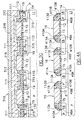
- FIGS 4A to 4D schematically show the main steps of a process according to a fourth embodiment of the present invention. As for the second and third embodiments, this process requires only three layers of polysilicon.
- the process according to this fourth embodiment provides for forming on the substrate 11 the gate oxide layer 12 (Figure 1A ), implanting and diffusing dopant ions to form the doped layer 14 for setting the memory cells threshold voltage (Figure 1B ), forming over the substrate top surface the first polysilicon layer 15 ( Figure 1C ), etching the first polysilicon layer 15 and the gate oxide 12 to form stripes 16 and optionally performing the write enhancement implant to form the doped regions 18 ( Figure 1D ), forming the ONO stack 19, 110, 111 over the top surface of the structure, depositing the second polysilicon layer 112 ( Figure 1F ) on the structure top surface and definining the polysilicon sidewall spacers 113A, 113B by means of an anisotropic etching of the second polysilicon layer 112.
- an etch process is performed to remove the previously formed ONO stack from over the polysilicon stripes 16 and in the exposed ONO stack portions in between the spacers 113A, 113B .
- "L"-shaped ONO stack portions 49A, 410A, 411A and 49B, 410B, 411B, covered by the spacers 113A and 113B, are thus left at the two sides of each stripe 16 .
- the "L"-shaped ONO stack portions at the sides of a generic stripe 16 are in this case physically separated from the "L"-shaped ONO stack portions at the sides of an adjacent stripe 16.
- an N type dopant is then selectively implanted and made to diffuse into the P type doped regions 18 to form N type bit line diffusions 415 extending parallelly to the stripes 16 .
- the dopant ions and the implant dose can for example be the same as the exemplary ones specified previously in connection with the first embodiment.
- the implant energy can be lower since the dopant ions do not have to pass through the ONO stack.
- this implant can be performed prior to the etching of the ONO stack, in which case same implant energies as those previously mentioned can be used.
- a silicide layer (not shown in the drawings) is formed in self-aligned manner over the bit line diffusions 415 , to reduce the resistance thereof.
- a layer 41 of a dielectric material is then formed on the structure top surface.
- the dielectric layer which can be for example a layer of TEOS with a thickness ranging from 1000 to 7000 ⁇ , has the main function of making the structure top surface substantially flat.
- the dielectric layer 41 is then removed non-selectively by means of a plasma etching or a CMP or a combination of these two processes down to the polysilicon stripes 16 .
- the upper part of the polysilicon stripes 16 of the "L"-shaped ONO portions 49A , 410A, 411A, and 49B, 410B, 411B and of the sidewall spacers 113A, 113B are removed.
- the resulting structure is schematically depicted in Figure 4D. Trapezoidal sidewall spacers 413A, 413B are thus obtained, having a flat top surface.
- the spaces between the spacers 413A, 413B remains filled with portions of the dielectric layer 41 .
- the structure top surface is substantially flat.
- a third layer 416 of polysilicon is formed on the structure top surface, for example by CVD.
- the third polysilicon layer has for example a thickness ranging from 1000 to 5000 ⁇ .
- the third polysilicon layer can be doped to increase the conductivity thereof.
- a silicide layer 418 is formed on top of the polysilicon layer 416 , to further increase the conductivity thereof.
- the silicide layer 418 and the third polysilicon layer 416 are selectively removed to define stripes 419 extending transversally to the bit line diffusions 415 .
- the stripes 419 form word lines of the memory cell array.
- the stripes 16 of the first polysilicon layer 15 , the portions of the dielectric layer 41, the sidewall spacers 413A, 413B and the "L"-shaped portions of ONO stack are also selectively etched to remove all these layers in the regions between the word lines 419 .
- a P type dopant such as boron is implanted and made to diffuse into the doped layer 14 for purposes of electrical isolation between the bit lines, in particular to prevent punch-through from occurring.
- a conventional dielectric stack 420 with good ionic gettering properties is then placed over the top surface of the structure.
- contact openings 421 are formed in the dielectric layer 420 down to the surface of the bit line diffusions 415 outside memory cells sub-arrays.
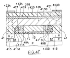
- metal bit lines 423A, 423B are defined running transversally to the word lines 419 over the bit line diffusions 415 and contacting the latter in prescribed areas outside the memory cell sub-arrays. Different arrangements of the metal bit lines are possible.
- the memory cell obtained by the process according to this fourth embodiment is functionally equivalent to that depicted in Figure 1N, and can be represented by the electrical equivalent circuit of Figure 1P.
- the memory cell of Figure 4F differs from that of Figure 1N for the fact that the space between the spacers 413A, 413B is not filled by polysilicon, but by dielectric. In this way, the parasitic capacitance of the word line 419 is significantly reduced. In fact, the capacitive coupling of the word line with the bit line diffusions 415 is smaller compared to the structure of Figure 1N .
- the spacers 413A , 413B which form the gates of the transistors T1 and T3 , are electrically connected to the word line 419 thanks to the fact that they have a small flat top surface. Additionally, thanks to the physical separation of the "L"-shaped ONO stack portions of adjacent memory cells along a same word line, the confinement of the charge in the nitride layer portions 410A, 410B is assured, and it is avoided any possible sharing of charge between two adjacent memory cells.
- the dual charge storage location memory cells fabricated by the processes previously described are characterized by the fact of having two physically separated "L"-shaped ONO stack portions, each one at a respective side of the gate of the central transistor T2.
- the "L"-shaped ONO stack portions comprise each a base portion lying on the substrate surface, and an upright portion lying on a respective side of the gate of the central transistor.
- the "L"-shaped ONO stack portions at the sides of the gate of a given memory cells are connected to the "L"-shaped ONO stack portions of the two adjacent memory cells along the word line of the memory cell array.
- the "L"-shaped ONO stack portions of any memory cell in the array are physically separated from the "L"-shaped ONO stack portions of the adjacent memory cells along the word line.
- the process according to the present invention is suitable for the manufacturing of dual charge storage location memory cells of the EPROM, EEPROM and Flash EPROM types.
- the dual charge storage location memory cell realized in accordance with the process of the invention are also adapted to be used as multi-level memory cells.
- Each transistor T1 and T3 would in this case store more than one bit, for example two bits in the case of four different threshold voltages.
- the memory cell storage capacity is twice the storage capacity of the individual transistors T1 and T3 .
- the silicon nitride layer may be substituted for by a different charge trapping dielectric material.
- the silicon dioxide layers forming the bottom and top layers of the ONO sandwich may be substituted for by different dielectrics, particularly high-k (i.e ., high dielectric constant) dielectrics such as the promising ZrO 2 and HfO 2 .
Landscapes
- Engineering & Computer Science (AREA)
- Microelectronics & Electronic Packaging (AREA)
- Power Engineering (AREA)
- Physics & Mathematics (AREA)
- Ceramic Engineering (AREA)
- Condensed Matter Physics & Semiconductors (AREA)
- General Physics & Mathematics (AREA)
- Computer Hardware Design (AREA)
- Non-Volatile Memory (AREA)
- Semiconductor Memories (AREA)
Abstract
Description
Claims (36)
- A process for manufacturing a dual charge storage location electrically programmable memory cell, comprising the steps of:characterized in that each of the charge-confining layers stack portions at the sides of the central gate is formed with an "L" shape, with a base charge-confining layers stack portion lying on the substrate surface and an upright charge-confining layers stack portion lying against a respective side of the central gate.forming a central insulated gate (12,15) over a semiconductor substrate (11) ;forming physically separated charge-confining layers stack portions of a dielectric/charge trapping material/dielectric layers stack (19,110,111;29,210,211;49A, B,410A,B,411A,B) at the sides of the central gate, the charge trapping material layer (110;210;410A,B) in each charge-confining layers stack portion forming a charge storage element;forming side control gates (113A,B;212;312;413A,B) over each of the charge-confining layers stack portions;forming memory cell source/drain regions (115;215;315;415) laterally to the side control gates;electrically connecting (116,117;216;312;416) the side control gates to the central gate,
- The process according to claim 1, in which the charge trapping material layer is a layer of silicon nitride.
- The process according to claim 1 or 2, in which the dielectric layers in the charge-confining layers stack portions are silicon oxide layers.
- The process according to claim 1 or 2, in which the dielectric layers in the charge-confining layers stack portions are high dielectric constant material layers.
- The process according to anyone of claims 1 to 4 comprising the steps of, after forming the central gate, introducing into the substrate dopants of the first conductivity type using the central gate as a mask, to form write enhancement doped regions (18;28) of the first conductivity type at the sides of the central gate, the write enhancement regions having a doping level higher than that of the substrate.
- The process according to anyone of claims 1 to 5, comprising the steps of:forming the dielectric-charge trapping material-dielectric layers stack (9,10,11) on the central gate and on the substrate surface at the sides of the central gate;forming a first polysilicon layer (112) on the layers stack, and anisotropically etching the first polysilicon layer to form sidewall spacers (113A,B) at the sides of the central gate;introducing dopants (114) of a second conductivity type into the substrate using the sidewall spacers as a mask, to form memory cell source/drain regions (115) at the sides of the sidewall spacers;forming second polysilicon layer portions (116) on the sidewall spacers and removing the layers stack from over the central gate;covering the central gate and the second polysilicon layer portions with a third polysilicon layer (117).
- The process according to claim 6, in which said forming second polysilicon layer portions on the sidewall spacers and removing the layers stack from over the central gate comprises the steps of:forming a second polysilicon layer (116) on the layers stack and on the sidewall spacers, andremoving the second polysilicon layer and the layers stack down to the central gate, leaving the second polysilicon layer portions to fill recesses at the sides of the sidewall spacers.
- The process according to claim 7, in which said removing the second polysilicon layer comprises performing a plasma etch or a chemical-mechanical polishing or a combination thereof.
- The process according to anyone of claims 1 to 5, comprising the steps of:covering the central gate and the substrate surface at the sides of the insulated gate with a masking layer (22) ;introducing dopants (214) of a second conductivity type into the substrate to form memory cell source/drain regions (215), the masking layer causing the source/drain regions to be spaced apart from the sides of the central gate;removing the masking layer and covering the central gate and the substrate surface with the dielectric-charge trapping material-dielectric layers stack (29,210,211);forming a first polysilicon layer (212) on the layers stack;removing the first polysilicon layer and the layers stack down to the central gate, leaving physically separated charge-confining layers stack portions of the dielectric-charge trapping material-dielectric layers stack covered by first polysilicon layer portions at the sides of the central gate;covering the central gate and the first polysilicon layer portions with a second polysilicon layer.
- The process according to claim 9, in which said covering the central gate and the substrate surface at the sides of the central gate with a masking layer comprises the steps of:forming on the central gate and on the substrate surface at the sides of the central gate an etch-stop layer (21) intended to act as an etch-stop in the step of removing the masking layer, andforming on the etch-stop layer the masking layer.
- The process according to claim 10, in which said etch-stop layer is an oxide layer and said masking layer is a nitride layer.
- The process according to claim 11, in which said removing the first polysilicon layer and the layers stack down to the central gate comprises performing a plasma etch or a chemical-mechanical polishing or a combination thereof.
- The process according to anyone of claims 1 to 5, comprising the steps of:forming the dielectric-charge trapping material-dielectric layers stack (9,10,11) on the central gate and on the substrate surface at the sides of the central gated;depositing a liquid-phase gap-fill material (31) on the layers stack and making the liquid-phase gap-fill material denser, the gap-fill material filling gaps between the layers stack at the sides of the central gate and the layers stack over the central gate, the latter being substantially free of gap-fill material;removing the layers stack from over the central gate using the gap-fill material as a protection to leave physically separated charge-confining layers stack portions of the dielectric-charge trapping material-dielectric layers stack at the sides of the central gate;removing the gap-fill material from over the charge-confining layers stack portions;forming a first polysilicon layer (312) over the central gate and over the charge-confining layers stack portions at the sides thereof;introducing dopants (314) of a second conductivity type into the substrate using the first polysilicon layer as a mask to form source/drain regions (215) spaced apart from the sides of the central gate;forming a second polysilicon layer (316) over the first polysilicon layer.
- The process according to claim 13, in which said depositing the liquid-phase gap-fill material comprises depositing the liquid-phase gap-fill material by spinning the substrate.
- The process according to claim 14, in which said liquid-phase gap-fill material is a bottom anti-reflecting coating material or a spin-on glass.
- The process according to claim 1 to 5, comprising the steps of:forming the dielectric-charge trapping material-dielectric layers stack (9,10,11) on the central gate and on the substrate surface at the sides of the central gate;forming a first polysilicon layer (112) on the layers stack, and etching the polysilicon layer to form sidewall spacers (113A,113B) at the sides of the central gate;introducing dopants (414) of a second conductivity type into the substrate using the sidewall spacers as a mask, to form source/drain regions (415) at the sides of the sidewall spacers;removing the layers stack from over the source/drain regions;forming a dielectric layer (41) over the central gate and the sidewall spacers, the dielectric layer filling gaps between the sidewall spacers and the source/drain regions;planarizing the structure down to the central gate, partially removing a top portion of the central gate and of the sidewall spacers to make a top surface thereof substantially flat, gap-filling portions of the dielectric layer filling gaps between the source/drain regions and the top surface of the sidewall spacers;covering the central gate, the sidewall spacers and the gap-filling portions of the dielectric layer with a polysilicon layer (416).
- The process according to claim 16, in which said planarizing the structure comprises performing a plasma etch or a chemical-mechanical polishing or a combination thereof.
- A process for manufacturing an array of electrically programmable dual charge storage location memory cells, comprising the steps of:characterized in that each of the charge-confining layers stack portions at the sides of the gate has an "L" shape, with a base charge-confining layers stack portion lying on the substrate surface and an upright charge-confining layers stack portion lying against a respective' side of the insulated gate.forming insulated gate stripes (16;26) over a semiconductor substrate (11);forming charge-confining layers stack portions of a dielectric-charge trapping material-dielectric layers stack (19,110,111;29,210,211;49A,B,410A,B,411A,B) over the substrate surface at the sides of the insulated gate stripes, the charge trapping material layer in each charge-confining layers stack portion forming a charge storage element;forming side control gates (113A,B;212;312;413A,B) over each of the charge-confining layers stack portions;forming bit line diffusions (115;215;315;415) in the substrate between the insulated gate stripes extending parallelly thereto;forming word lines (119;219;319;419) transversal to the insulated gate stripes electrically connecting the side control gates and the insulated gate stripes;removing the insulated gate stripes and the charge-confining layers stack portions in regions between the word lines to form physically separated insulated gates and charge-confining layers stack portions for the memory cells of the array,
- The process according to claim 18, in which the charge trapping material layer is a layer of silicon nitride.
- The process according to claim 18 or 19, in which the dielectrics in the charge-confining layers stack portions are silicon oxide.
- The process according to claim 18 or 19, in which the dielectrics in the charge-confining layers stack portions are a high dielectric constant material.
- The process according to anyone of claims 18 to 21, comprising the steps of, after forming the insulated gate stripes, introducing into the substrate dopants of the first conductivity type using the insulated gate stripes as a mask, to form write enhancement doped regions (18;28) of the first conductivity type between the insulated gate stripes, the write enhancement region having a doping level higher than that of the substrate.
- The process according to anyone of claims 18 to 22, comprising the steps of:forming the dielectric-charge trapping material-dielectric layers stack (9,10,11) on the insulated gate stripes and on the substrate surface between the insulated gate stripes;forming a first polysilicon layer (112) on the layers stack, and anisotropically etching the polysilicon layer to form sidewall spacers (113A,113B) at the sides of the insulated gate stripes;introducing dopants (114) of a second conductivity type in the substrate using the sidewall spacers as a mask, to form bit line diffusions (115) between the insulated gate stripes and extending parallelly thereto;depositing a second polysilicon layer (116) and removing the second polysilicon layer and the layers stack down to the insulated gate stripes, thereby leaving charge-confining layers stack portions of the layers stack on the substrate surface between the insulated gate stripes and second polysilicon layer portions filling gaps between the charge-confining layers stack portions and a top surface of the insulated gate stripes;depositing and patterning a third polysilicon layer (117) to form word lines (119) transversal to the insulated gate stripes;selectively removing the insulated gate stripes, the sidewall spacers, the charge-confining layers stack portions and the second polysilicon layer portions from regions in between the word lines.
- The process according to claim 23, in which said forming second polysilicon layer portions on the sidewall spacers and removing the layers stack from over the insulated gate stripes comprises the steps of:forming a second polysilicon layer (116) on the layers stack and on the sidewall spacers, andremoving the second polysilicon layer and the layers stack down to the insulated gate stripes, leaving the second polysilicon layer portions to fill recesses at the sides of the sidewall spacers.
- The process according to claim 24, in which said removing the second polysilicon layer comprises performing a plasma etch or a chemical-mechanical polishing or a combination thereof.
- The process according to anyone of claims 18 to 21, comprising the steps of:covering the insulated gate stripes and the substrate surface therebetween with a masking layer (22);introducing dopants (214) of a second conductivity type into the substrate to form bit line diffusions (215)extending parallelly to the insulated gate stripes, the masking layer causing the bit line diffusions to be spaced apart from the sides of the insulated gate stripes;removing the masking layer and covering the insulated gate stripes and the substrate surface with the dielectric-charge trapping material-dielectric layers stack (29,210,211);depositing a first polysilicon layer (212) on the layers stack;removing the first polysilicon layer and the layers stack down to the insulated gate stripes, leaving charge-confining layers stack portions of the dielectric-charge trapping material-dielectric layers stack covered by first polysilicon layer portions on the substrate surface between the insulated gate stripes;depositing and patterning a third polysilicon layer (216) to form word lines (219) transversal to the insulated gate stripes;selectively removing the insulated gate stripes, the charge-confining layers stack portions and the first polysilicon layer portions from regions in between the word lines.
- The process according to claim 26, in which said covering the insulated gate stripes and the substrate surface at the sides of the insulated gate stripes with a masking layer comprises the steps of:forming on the insulated gate stripes and on the substrate surface between the insulated gate stripes an etch-stop layer (21) intended to act as an etch-stop in the step of removing the masking layer, andforming on the etch-stop layer the masking layer.
- The process according to claim 27, in which said etch-stop layer is an oxide layer and said masking layer is a nitride layer.
- The process according to claim 28, in which said removing the first polysilicon layer and the layers stack down to the insulated gate stripes comprises performing a plasma etch or a chemical-mechanical polishing or a combination thereof.
- The process according to anyone of claims 18 to 21, comprising the steps of:forming the dielectric-charge trapping material-dielectric layers stack (9,10,11) on the insulated gate stripes and on the substrate surface therebetween;depositing a liquid-phase gap-fill material (31) on the layers stack and making the liquid-phase gap-fill material denser, the gap-fill material filling gaps in the layers stack between the insulated gate stripes and the layers stack over the insulated gate stripes, the latter being substantially free of gap-fill material;removing the layers stack from over the insulated gate stripes using the gap-fill material as a protection to leave charge-confining layers stack portions of the dielectric-charge trapping material-dielectric layers stack in between the insulated gate stripes;removing the gap-fill material from over the charge-confining layers stack portions;depositing a first polysilicon layer (312);introducing dopants (314) of a second conductivity type into the substrate using the first polysilicon layer as a mask to form bit line diffusions (315) spaced apart from the sides of the insulated gate stripes;depositing a second polysilicon layer (316);patterning the third polysilicon layer and the second polysilicon layer to form word lines (319) transversal to the insulated gate stripes;selectively removing the insulated gate stripes and the charge-confining layers stack portions from regions in between the word lines.
- The process according to claim 32, in which said depositing the liquid-phase gap-fill material comprises depositing the liquid-phase gap-fill material by spinning the substrate.
- The process according to claim 31, in which said liquid-phase gap-fill material is a bottom anti-reflecting coating material or a spin-on glass.
- The process according to anyone of claims 18 to 21, comprising the steps of:forming the dielectric-charge trapping material-dielectric layers stack (9,10,11) on the insulated gate stripes and on the substrate surface therebetween;forming a first polysilicon layer (112) on the layers stack, and etching the polysilicon layer to form sidewall spacers (113A,113B) at the sides of the insulated gate stripes;introducing dopants (414) of a second conductivity type into the substrate using the sidewall spacers as a mask, to form bit line diffusions (415) between the insulated gate stripes extending parallelly thereto;removing the layers stack from over the bit line diffusions;depositing a dielectric layer (41), the dielectric layer filling gaps between the insulated gate stripes;planarizing the structure down to the insulated gate stripes, partially removing a top portion of the insulated gate stripes and of the sidewall spacers to make a top surface thereof substantially flat, gap-filling portions of the dielectric layer filling gaps between the insulated gate stripes;depositing and patterning a second polysilicon layer (416) to form word lines (419);selectively removing the insulated gate stripes, the sidewall spacers and the dielectric-charge trapping material-dielectric layers stack from regions in between the word lines.
- The process according to claim 33, in which said planarizing the structure comprises performing a plasma etch or a chemical-mechanical polishing or a combination thereof.
- A dual charge storage location electrically programmable memory cell, comprising an insulated gate (15) placed over a semiconductor substrate (11), physically separated charge-confining layers stack portions of a dielectric-charge trapping material-dielectric layers stack (19,110,111;29,210,211;49A,B,410A,B,411A,B) on a substrate surface at the sides of the gate, the charge trapping material layer in each charge-confining layers stack portion forming a floating gate, side control gates (113A,B;212;312;413A,B) over each of the charge-confining layers stack portions, memory cell source/drain regions (115;215;315;415) lateral to the side control gates and an electrical connection element (116,117;216;312;416) connecting the side control gates to the gate,
characterized in that each of the charge-confining layers stack portions at the sides of the gate has an "L" shape, with a base charge-confining layers stack portion lying on the substrate surface and an upright charge-confining layers stack portion lying against a respective side of the insulated gate. - The dual charge storage location memory cell according to claim 35, in which said side control gates are polysilicon sidewall spacers formed at the sides of the insulated gate.
Priority Applications (4)
| Application Number | Priority Date | Filing Date | Title |
|---|---|---|---|
| EP01830634A EP1300888B1 (en) | 2001-10-08 | 2001-10-08 | Process for manufacturing a dual charge storage location memory cell |
| JP2002294069A JP2003163294A (en) | 2001-10-08 | 2002-10-07 | Method for manufacturing memory cell |
| US10/267,033 US6825523B2 (en) | 2001-10-08 | 2002-10-07 | Process for manufacturing a dual charge storage location memory cell |
| US10/964,049 US7115472B2 (en) | 2001-10-08 | 2004-10-12 | Process for manufacturing a dual charge storage location memory cell |
Applications Claiming Priority (1)
| Application Number | Priority Date | Filing Date | Title |
|---|---|---|---|
| EP01830634A EP1300888B1 (en) | 2001-10-08 | 2001-10-08 | Process for manufacturing a dual charge storage location memory cell |
Publications (2)
| Publication Number | Publication Date |
|---|---|
| EP1300888A1 true EP1300888A1 (en) | 2003-04-09 |
| EP1300888B1 EP1300888B1 (en) | 2013-03-13 |
Family
ID=8184725
Family Applications (1)
| Application Number | Title | Priority Date | Filing Date |
|---|---|---|---|
| EP01830634A Expired - Lifetime EP1300888B1 (en) | 2001-10-08 | 2001-10-08 | Process for manufacturing a dual charge storage location memory cell |
Country Status (3)
| Country | Link |
|---|---|
| US (2) | US6825523B2 (en) |
| EP (1) | EP1300888B1 (en) |
| JP (1) | JP2003163294A (en) |
Cited By (4)
| Publication number | Priority date | Publication date | Assignee | Title |
|---|---|---|---|---|
| WO2006110395A1 (en) * | 2005-04-07 | 2006-10-19 | Spansion Llc | Split gate multi-bit memory cell |
| WO2007089949A2 (en) * | 2006-02-04 | 2007-08-09 | Spansion Llc | Memory cells having split charge storage nodes and methods for fabricating memory cells having split charge storage nodes |
| CN100587838C (en) * | 2003-05-22 | 2010-02-03 | 飞思卡尔半导体公司 | Memory with charge storage locations |
| US9159568B2 (en) | 2006-02-04 | 2015-10-13 | Cypress Semiconductor Corporation | Method for fabricating memory cells having split charge storage nodes |
Families Citing this family (43)
| Publication number | Priority date | Publication date | Assignee | Title |
|---|---|---|---|---|
| JP3664161B2 (en) * | 2002-10-30 | 2005-06-22 | セイコーエプソン株式会社 | Semiconductor device and manufacturing method thereof |
| KR100501464B1 (en) * | 2003-02-04 | 2005-07-18 | 동부아남반도체 주식회사 | Method for manufacturing non-volatile memory devices |
| JP2004342767A (en) * | 2003-05-14 | 2004-12-02 | Sharp Corp | Semiconductor memory, semiconductor device, and portable electronic equipment |
| US6869843B2 (en) * | 2003-06-27 | 2005-03-22 | Macronix International Co., Ltd. | Non-volatile memory cell with dielectric spacers along sidewalls of a component stack, and method for forming same |
| US7184315B2 (en) * | 2003-11-04 | 2007-02-27 | Micron Technology, Inc. | NROM flash memory with self-aligned structural charge separation |
| US7235848B2 (en) * | 2003-12-09 | 2007-06-26 | Applied Intellectual Properties Co., Ltd. | Nonvolatile memory with spacer trapping structure |
| US7221018B2 (en) * | 2004-02-10 | 2007-05-22 | Micron Technology, Inc. | NROM flash memory with a high-permittivity gate dielectric |
| JP4640918B2 (en) * | 2004-03-11 | 2011-03-02 | ルネサスエレクトロニクス株式会社 | Nonvolatile semiconductor memory device and manufacturing method thereof |
| US7387932B2 (en) * | 2004-07-06 | 2008-06-17 | Macronix International Co., Ltd. | Method for manufacturing a multiple-gate charge trapping non-volatile memory |
| US7067375B1 (en) * | 2004-12-20 | 2006-06-27 | Macronix International Co., Ltd. | Non-volatile memory and method for fabricating the same |
| US7315474B2 (en) | 2005-01-03 | 2008-01-01 | Macronix International Co., Ltd | Non-volatile memory cells, memory arrays including the same and methods of operating cells and arrays |
| US8482052B2 (en) | 2005-01-03 | 2013-07-09 | Macronix International Co., Ltd. | Silicon on insulator and thin film transistor bandgap engineered split gate memory |
| US7473589B2 (en) | 2005-12-09 | 2009-01-06 | Macronix International Co., Ltd. | Stacked thin film transistor, non-volatile memory devices and methods for fabricating the same |
| US7476926B2 (en) | 2005-01-06 | 2009-01-13 | International Business Machines Corporation | Eraseable nonvolatile memory with sidewall storage |
| TWI261340B (en) * | 2005-04-26 | 2006-09-01 | Macronix Int Co Ltd | Non-volatile memory and fabricating method thereof and operation thereof |
| JP5053084B2 (en) * | 2005-05-30 | 2012-10-17 | スパンション エルエルシー | Semiconductor device and manufacturing method thereof |
| US7329578B2 (en) * | 2005-06-20 | 2008-02-12 | Taiwan Semiconductor Manufacturing Co., Ltd. | Method of forming floating-gate tip for split-gate flash memory process |
| US7528425B2 (en) * | 2005-07-29 | 2009-05-05 | Infineon Technologies Ag | Semiconductor memory with charge-trapping stack arrangement |
| US7763927B2 (en) * | 2005-12-15 | 2010-07-27 | Macronix International Co., Ltd. | Non-volatile memory device having a nitride-oxide dielectric layer |
| US7244642B2 (en) * | 2005-09-16 | 2007-07-17 | Texas Instruments Incorporated | Method to obtain fully silicided gate electrodes |
| KR100643468B1 (en) * | 2005-12-01 | 2006-11-10 | 동부일렉트로닉스 주식회사 | Nonvolatile memory devices having insulating spacer and manufacturing method thereof |
| US7811915B2 (en) * | 2006-05-01 | 2010-10-12 | Spansion Llc | Method for forming bit lines for semiconductor devices |
| US7907450B2 (en) * | 2006-05-08 | 2011-03-15 | Macronix International Co., Ltd. | Methods and apparatus for implementing bit-by-bit erase of a flash memory device |
| TWI333691B (en) * | 2006-05-23 | 2010-11-21 | Ememory Technology Inc | Nonvolatile memory with twin gate and method of operating the same |
| US20070278556A1 (en) * | 2006-05-30 | 2007-12-06 | Ya-Chin King | Two bits non volatile memory cells and method of operating the same |
| US7755132B2 (en) | 2006-08-16 | 2010-07-13 | Sandisk Corporation | Nonvolatile memories with shaped floating gates |
| US7494860B2 (en) * | 2006-08-16 | 2009-02-24 | Sandisk Corporation | Methods of forming nonvolatile memories with L-shaped floating gates |
| US20080121982A1 (en) * | 2006-08-17 | 2008-05-29 | Hocine Boubekeur | Semiconductor structure, semiconductor memory device and method of manufacturing the same |
| KR100870321B1 (en) * | 2006-09-29 | 2008-11-25 | 주식회사 하이닉스반도체 | Method of manufacturing flash memory device |
| US7811890B2 (en) * | 2006-10-11 | 2010-10-12 | Macronix International Co., Ltd. | Vertical channel transistor structure and manufacturing method thereof |
| US8772858B2 (en) * | 2006-10-11 | 2014-07-08 | Macronix International Co., Ltd. | Vertical channel memory and manufacturing method thereof and operating method using the same |
| US20090039414A1 (en) * | 2007-08-09 | 2009-02-12 | Macronix International Co., Ltd. | Charge trapping memory cell with high speed erase |
| US20090309150A1 (en) * | 2008-06-13 | 2009-12-17 | Infineon Technologies Ag | Semiconductor Device And Method For Making Semiconductor Device |
| US8329545B1 (en) * | 2008-12-30 | 2012-12-11 | Micron Technology, Inc. | Method of fabricating a charge trap NAND flash memory |
| US8383443B2 (en) | 2010-05-14 | 2013-02-26 | International Business Machines Corporation | Non-uniform gate dielectric charge for pixel sensor cells and methods of manufacturing |
| US9240405B2 (en) | 2011-04-19 | 2016-01-19 | Macronix International Co., Ltd. | Memory with off-chip controller |
| US9082651B2 (en) | 2013-09-27 | 2015-07-14 | Taiwan Semiconductor Manufacturing Company, Ltd. | Memory devices and method of forming same |
| US9076681B2 (en) * | 2013-09-27 | 2015-07-07 | Taiwan Semiconductor Manufacturing Company, Ltd. | Memory devices and method of fabricating same |
| US9559177B2 (en) | 2013-12-03 | 2017-01-31 | Taiwan Semiconductor Manufacturing Company, Ltd. | Memory devices and method of fabricating same |
| US8916432B1 (en) * | 2014-01-21 | 2014-12-23 | Cypress Semiconductor Corporation | Methods to integrate SONOS into CMOS flow |
| US9691883B2 (en) * | 2014-06-19 | 2017-06-27 | Taiwan Semiconductor Manufacturing Co., Ltd. | Asymmetric formation approach for a floating gate of a split gate flash memory structure |
| JP2019102520A (en) * | 2017-11-29 | 2019-06-24 | ルネサスエレクトロニクス株式会社 | Semiconductor device manufacturing method |
| US11069564B2 (en) * | 2019-04-09 | 2021-07-20 | International Business Machines Corporation | Double metal patterning |
Citations (3)
| Publication number | Priority date | Publication date | Assignee | Title |
|---|---|---|---|---|
| US5408115A (en) * | 1994-04-04 | 1995-04-18 | Motorola Inc. | Self-aligned, split-gate EEPROM device |
| WO2001017030A1 (en) * | 1999-08-27 | 2001-03-08 | Macronix America, Inc. | Non-volatile memory structure for twin-bit storage and methods of making same |
| JP2001156188A (en) * | 1999-03-08 | 2001-06-08 | Toshiba Corp | Semiconductor storage device and method for manufacturing the same |
Family Cites Families (5)
| Publication number | Priority date | Publication date | Assignee | Title |
|---|---|---|---|---|
| US5949711A (en) | 1996-09-26 | 1999-09-07 | Waferscale Integration, Inc. | Dual bit memory cell |
| US6030871A (en) | 1998-05-05 | 2000-02-29 | Saifun Semiconductors Ltd. | Process for producing two bit ROM cell utilizing angled implant |
| US6248633B1 (en) | 1999-10-25 | 2001-06-19 | Halo Lsi Design & Device Technology, Inc. | Process for making and programming and operating a dual-bit multi-level ballistic MONOS memory |
| US6413821B1 (en) * | 2001-09-18 | 2002-07-02 | Seiko Epson Corporation | Method of fabricating semiconductor device including nonvolatile memory and peripheral circuit |
| EP1313149A1 (en) * | 2001-11-14 | 2003-05-21 | STMicroelectronics S.r.l. | Process for fabricating a dual charge storage location memory cell |
-
2001
- 2001-10-08 EP EP01830634A patent/EP1300888B1/en not_active Expired - Lifetime
-
2002
- 2002-10-07 JP JP2002294069A patent/JP2003163294A/en active Pending
- 2002-10-07 US US10/267,033 patent/US6825523B2/en not_active Expired - Lifetime
-
2004
- 2004-10-12 US US10/964,049 patent/US7115472B2/en not_active Expired - Lifetime
Patent Citations (4)
| Publication number | Priority date | Publication date | Assignee | Title |
|---|---|---|---|---|
| US5408115A (en) * | 1994-04-04 | 1995-04-18 | Motorola Inc. | Self-aligned, split-gate EEPROM device |
| JP2001156188A (en) * | 1999-03-08 | 2001-06-08 | Toshiba Corp | Semiconductor storage device and method for manufacturing the same |
| US6335554B1 (en) * | 1999-03-08 | 2002-01-01 | Kabushiki Kaisha Toshiba | Semiconductor Memory |
| WO2001017030A1 (en) * | 1999-08-27 | 2001-03-08 | Macronix America, Inc. | Non-volatile memory structure for twin-bit storage and methods of making same |
Non-Patent Citations (1)
| Title |
|---|
| PATENT ABSTRACTS OF JAPAN vol. 2000, no. 23 10 February 2001 (2001-02-10) * |
Cited By (6)
| Publication number | Priority date | Publication date | Assignee | Title |
|---|---|---|---|---|
| CN100587838C (en) * | 2003-05-22 | 2010-02-03 | 飞思卡尔半导体公司 | Memory with charge storage locations |
| WO2006110395A1 (en) * | 2005-04-07 | 2006-10-19 | Spansion Llc | Split gate multi-bit memory cell |
| US7312495B2 (en) | 2005-04-07 | 2007-12-25 | Spansion Llc | Split gate multi-bit memory cell |
| WO2007089949A2 (en) * | 2006-02-04 | 2007-08-09 | Spansion Llc | Memory cells having split charge storage nodes and methods for fabricating memory cells having split charge storage nodes |
| WO2007089949A3 (en) * | 2006-02-04 | 2007-11-29 | Spansion Llc | Memory cells having split charge storage nodes and methods for fabricating memory cells having split charge storage nodes |
| US9159568B2 (en) | 2006-02-04 | 2015-10-13 | Cypress Semiconductor Corporation | Method for fabricating memory cells having split charge storage nodes |
Also Published As
| Publication number | Publication date |
|---|---|
| US20030067032A1 (en) | 2003-04-10 |
| US6825523B2 (en) | 2004-11-30 |
| US7115472B2 (en) | 2006-10-03 |
| JP2003163294A (en) | 2003-06-06 |
| EP1300888B1 (en) | 2013-03-13 |
| US20050064654A1 (en) | 2005-03-24 |
Similar Documents
| Publication | Publication Date | Title |
|---|---|---|
| EP1300888B1 (en) | Process for manufacturing a dual charge storage location memory cell | |
| US7906397B2 (en) | Methods of fabricating nonvolatile semiconductor memory devices including a plurality of stripes having impurity layers therein | |
| US7037787B2 (en) | Flash memory with trench select gate and fabrication process | |
| US7208376B2 (en) | Self aligned method of forming a semiconductor memory array of floating gate memory cells with buried floating gate and pointed channel region | |
| US7186607B2 (en) | Charge-trapping memory device and method for production | |
| KR101036669B1 (en) | Array source line in nand flash memory | |
| US7163863B2 (en) | Vertical memory cell and manufacturing method thereof | |
| US20050148173A1 (en) | Non-volatile memory array having vertical transistors and manufacturing method thereof | |
| US7126188B2 (en) | Vertical split gate memory cell and manufacturing method thereof | |
| US6344393B1 (en) | Fully recessed semiconductor method for low power applications | |
| US7375387B2 (en) | Method for producing semiconductor memory devices and integrated memory device | |
| US6147378A (en) | Fully recessed semiconductor device and method for low power applications with single wrap around buried drain region | |
| US11183509B2 (en) | Non-volatile memory with silicided bit line contacts | |
| KR100660551B1 (en) | Non-volatile memory device and method for forming thereof | |
| US6011288A (en) | Flash memory cell with vertical channels, and source/drain bus lines | |
| US7094648B2 (en) | Method for fabricating an NROM memory cell array | |
| US6958510B2 (en) | Process for fabricating a dual charge storage location memory cell | |
| US6987048B1 (en) | Memory device having silicided bitlines and method of forming the same | |
| US7214586B2 (en) | Methods of fabricating nonvolatile memory device | |
| US20050032308A1 (en) | Multi-bit vertical memory cell and method of fabricating the same | |
| US6882001B2 (en) | Electrically-programmable non-volatile memory cell |
Legal Events
| Date | Code | Title | Description |
|---|---|---|---|
| PUAI | Public reference made under article 153(3) epc to a published international application that has entered the european phase |
Free format text: ORIGINAL CODE: 0009012 |
|
| AK | Designated contracting states |
Kind code of ref document: A1 Designated state(s): AT BE CH CY DE DK ES FI FR GB GR IE IT LI LU MC NL PT SE TR Designated state(s): AT BE CH CY DE DK ES FI FR GB GR IE IT LI LU MC NL PT SE TR |
|
| AX | Request for extension of the european patent |
Extension state: AL LT LV MK RO SI |
|
| 17P | Request for examination filed |
Effective date: 20030329 |
|
| AKX | Designation fees paid |
Designated state(s): DE FR GB IT |
|
| 17Q | First examination report despatched |
Effective date: 20070219 |
|
| RAP1 | Party data changed (applicant data changed or rights of an application transferred) |
Owner name: STMICROELECTRONICS SRL |
|
| RAP1 | Party data changed (applicant data changed or rights of an application transferred) |
Owner name: STMICROELECTRONICS SRL |
|
| GRAP | Despatch of communication of intention to grant a patent |
Free format text: ORIGINAL CODE: EPIDOSNIGR1 |
|
| GRAS | Grant fee paid |
Free format text: ORIGINAL CODE: EPIDOSNIGR3 |
|
| GRAA | (expected) grant |
Free format text: ORIGINAL CODE: 0009210 |
|
| AK | Designated contracting states |
Kind code of ref document: B1 Designated state(s): DE FR GB IT |
|
| REG | Reference to a national code |
Ref country code: GB Ref legal event code: FG4D |
|
| REG | Reference to a national code |
Ref country code: DE Ref legal event code: R096 Ref document number: 60147761 Country of ref document: DE Effective date: 20130508 |
|
| REG | Reference to a national code |
Ref country code: GB Ref legal event code: 732E Free format text: REGISTERED BETWEEN 20130718 AND 20130724 |
|
| REG | Reference to a national code |
Ref country code: DE Ref legal event code: R082 Ref document number: 60147761 Country of ref document: DE Representative=s name: WP THOMPSON, GB |
|
| PLBE | No opposition filed within time limit |
Free format text: ORIGINAL CODE: 0009261 |
|
| STAA | Information on the status of an ep patent application or granted ep patent |
Free format text: STATUS: NO OPPOSITION FILED WITHIN TIME LIMIT |
|
| REG | Reference to a national code |
Ref country code: DE Ref legal event code: R082 Ref document number: 60147761 Country of ref document: DE Representative=s name: WP THOMPSON, GB Effective date: 20131209 Ref country code: DE Ref legal event code: R081 Ref document number: 60147761 Country of ref document: DE Owner name: MICRON TECHNOLOGY, INC., US Free format text: FORMER OWNER: STMICROELECTRONICS SRL, AGRATE BRIANZA, IT Effective date: 20131209 Ref country code: DE Ref legal event code: R081 Ref document number: 60147761 Country of ref document: DE Owner name: MICRON TECHNOLOGY, INC., US Free format text: FORMER OWNER: STMICROELECTRONICS S.R.L., AGRATE BRIANZA, IT Effective date: 20130313 Ref country code: DE Ref legal event code: R081 Ref document number: 60147761 Country of ref document: DE Owner name: MICRON TECHNOLOGY, INC., BOISE, US Free format text: FORMER OWNER: STMICROELECTRONICS S.R.L., AGRATE BRIANZA, MAILAND/MILANO, IT Effective date: 20130313 Ref country code: DE Ref legal event code: R081 Ref document number: 60147761 Country of ref document: DE Owner name: MICRON TECHNOLOGY, INC., BOISE, US Free format text: FORMER OWNER: STMICROELECTRONICS SRL, AGRATE BRIANZA, IT Effective date: 20131209 Ref country code: DE Ref legal event code: R081 Ref document number: 60147761 Country of ref document: DE Owner name: MICRON TECHNOLOGY, INC., BOISE, US Free format text: FORMER OWNER: STMICROELECTRONICS S.R.L., AGRATE BRIANZA, IT Effective date: 20130313 |
|
| 26N | No opposition filed |
Effective date: 20131216 |
|
| PG25 | Lapsed in a contracting state [announced via postgrant information from national office to epo] |
Ref country code: IT Free format text: LAPSE BECAUSE OF FAILURE TO SUBMIT A TRANSLATION OF THE DESCRIPTION OR TO PAY THE FEE WITHIN THE PRESCRIBED TIME-LIMIT Effective date: 20130313 |
|
| REG | Reference to a national code |
Ref country code: DE Ref legal event code: R097 Ref document number: 60147761 Country of ref document: DE Effective date: 20131216 |
|
| REG | Reference to a national code |
Ref country code: FR Ref legal event code: ST Effective date: 20140630 |
|
| PG25 | Lapsed in a contracting state [announced via postgrant information from national office to epo] |
Ref country code: FR Free format text: LAPSE BECAUSE OF NON-PAYMENT OF DUE FEES Effective date: 20131031 |
|
| PGFP | Annual fee paid to national office [announced via postgrant information from national office to epo] |
Ref country code: GB Payment date: 20201027 Year of fee payment: 20 |
|
| PGFP | Annual fee paid to national office [announced via postgrant information from national office to epo] |
Ref country code: DE Payment date: 20201228 Year of fee payment: 20 |
|
| REG | Reference to a national code |
Ref country code: DE Ref legal event code: R082 Ref document number: 60147761 Country of ref document: DE Representative=s name: HOEGER, STELLRECHT & PARTNER PATENTANWAELTE MB, DE |
|
| REG | Reference to a national code |
Ref country code: DE Ref legal event code: R071 Ref document number: 60147761 Country of ref document: DE |
|
| REG | Reference to a national code |
Ref country code: GB Ref legal event code: PE20 Expiry date: 20211007 |
|
| PG25 | Lapsed in a contracting state [announced via postgrant information from national office to epo] |
Ref country code: GB Free format text: LAPSE BECAUSE OF EXPIRATION OF PROTECTION Effective date: 20211007 |