EP1302648A2 - Method for controlling engine exhaust gas system - Google Patents
Method for controlling engine exhaust gas system Download PDFInfo
- Publication number
- EP1302648A2 EP1302648A2 EP03000710A EP03000710A EP1302648A2 EP 1302648 A2 EP1302648 A2 EP 1302648A2 EP 03000710 A EP03000710 A EP 03000710A EP 03000710 A EP03000710 A EP 03000710A EP 1302648 A2 EP1302648 A2 EP 1302648A2
- Authority
- EP
- European Patent Office
- Prior art keywords
- oxygen
- sensor
- exhaust gas
- fuel ratio
- nitrogen oxide
- Prior art date
- Legal status (The legal status is an assumption and is not a legal conclusion. Google has not performed a legal analysis and makes no representation as to the accuracy of the status listed.)
- Granted
Links
Images


Classifications
-
- G—PHYSICS
- G01—MEASURING; TESTING
- G01N—INVESTIGATING OR ANALYSING MATERIALS BY DETERMINING THEIR CHEMICAL OR PHYSICAL PROPERTIES
- G01N27/00—Investigating or analysing materials by the use of electric, electrochemical, or magnetic means
- G01N27/26—Investigating or analysing materials by the use of electric, electrochemical, or magnetic means by investigating electrochemical variables; by using electrolysis or electrophoresis
- G01N27/416—Systems
- G01N27/417—Systems using cells, i.e. more than one cell and probes with solid electrolytes
- G01N27/4175—Calibrating or checking the analyser
-
- B—PERFORMING OPERATIONS; TRANSPORTING
- B01—PHYSICAL OR CHEMICAL PROCESSES OR APPARATUS IN GENERAL
- B01D—SEPARATION
- B01D53/00—Separation of gases or vapours; Recovering vapours of volatile solvents from gases; Chemical or biological purification of waste gases, e.g. engine exhaust gases, smoke, fumes, flue gases, aerosols
- B01D53/34—Chemical or biological purification of waste gases
- B01D53/92—Chemical or biological purification of waste gases of engine exhaust gases
- B01D53/94—Chemical or biological purification of waste gases of engine exhaust gases by catalytic processes
- B01D53/9495—Controlling the catalytic process
-
- F—MECHANICAL ENGINEERING; LIGHTING; HEATING; WEAPONS; BLASTING
- F01—MACHINES OR ENGINES IN GENERAL; ENGINE PLANTS IN GENERAL; STEAM ENGINES
- F01N—GAS-FLOW SILENCERS OR EXHAUST APPARATUS FOR MACHINES OR ENGINES IN GENERAL; GAS-FLOW SILENCERS OR EXHAUST APPARATUS FOR INTERNAL COMBUSTION ENGINES
- F01N11/00—Monitoring or diagnostic devices for exhaust-gas treatment apparatus, e.g. for catalytic activity
-
- F—MECHANICAL ENGINEERING; LIGHTING; HEATING; WEAPONS; BLASTING
- F02—COMBUSTION ENGINES; HOT-GAS OR COMBUSTION-PRODUCT ENGINE PLANTS
- F02D—CONTROLLING COMBUSTION ENGINES
- F02D41/00—Electrical control of supply of combustible mixture or its constituents
- F02D41/02—Circuit arrangements for generating control signals
- F02D41/14—Introducing closed-loop corrections
- F02D41/1438—Introducing closed-loop corrections using means for determining characteristics of the combustion gases; Sensors therefor
- F02D41/1439—Introducing closed-loop corrections using means for determining characteristics of the combustion gases; Sensors therefor characterised by the position of the sensor
- F02D41/1441—Plural sensors
-
- F—MECHANICAL ENGINEERING; LIGHTING; HEATING; WEAPONS; BLASTING
- F02—COMBUSTION ENGINES; HOT-GAS OR COMBUSTION-PRODUCT ENGINE PLANTS
- F02D—CONTROLLING COMBUSTION ENGINES
- F02D41/00—Electrical control of supply of combustible mixture or its constituents
- F02D41/02—Circuit arrangements for generating control signals
- F02D41/14—Introducing closed-loop corrections
- F02D41/1438—Introducing closed-loop corrections using means for determining characteristics of the combustion gases; Sensors therefor
- F02D41/1444—Introducing closed-loop corrections using means for determining characteristics of the combustion gases; Sensors therefor characterised by the characteristics of the combustion gases
- F02D41/1454—Introducing closed-loop corrections using means for determining characteristics of the combustion gases; Sensors therefor characterised by the characteristics of the combustion gases the characteristics being an oxygen content or concentration or the air-fuel ratio
-
- F—MECHANICAL ENGINEERING; LIGHTING; HEATING; WEAPONS; BLASTING
- F02—COMBUSTION ENGINES; HOT-GAS OR COMBUSTION-PRODUCT ENGINE PLANTS
- F02D—CONTROLLING COMBUSTION ENGINES
- F02D41/00—Electrical control of supply of combustible mixture or its constituents
- F02D41/02—Circuit arrangements for generating control signals
- F02D41/14—Introducing closed-loop corrections
- F02D41/1438—Introducing closed-loop corrections using means for determining characteristics of the combustion gases; Sensors therefor
- F02D41/1444—Introducing closed-loop corrections using means for determining characteristics of the combustion gases; Sensors therefor characterised by the characteristics of the combustion gases
- F02D41/146—Introducing closed-loop corrections using means for determining characteristics of the combustion gases; Sensors therefor characterised by the characteristics of the combustion gases the characteristics being an NOx content or concentration
-
- F—MECHANICAL ENGINEERING; LIGHTING; HEATING; WEAPONS; BLASTING
- F02—COMBUSTION ENGINES; HOT-GAS OR COMBUSTION-PRODUCT ENGINE PLANTS
- F02D—CONTROLLING COMBUSTION ENGINES
- F02D41/00—Electrical control of supply of combustible mixture or its constituents
- F02D41/02—Circuit arrangements for generating control signals
- F02D41/14—Introducing closed-loop corrections
- F02D41/1438—Introducing closed-loop corrections using means for determining characteristics of the combustion gases; Sensors therefor
- F02D41/1493—Details
- F02D41/1495—Detection of abnormalities in the air/fuel ratio feedback system
-
- G—PHYSICS
- G01—MEASURING; TESTING
- G01N—INVESTIGATING OR ANALYSING MATERIALS BY DETERMINING THEIR CHEMICAL OR PHYSICAL PROPERTIES
- G01N27/00—Investigating or analysing materials by the use of electric, electrochemical, or magnetic means
- G01N27/26—Investigating or analysing materials by the use of electric, electrochemical, or magnetic means by investigating electrochemical variables; by using electrolysis or electrophoresis
- G01N27/416—Systems
- G01N27/417—Systems using cells, i.e. more than one cell and probes with solid electrolytes
-
- F—MECHANICAL ENGINEERING; LIGHTING; HEATING; WEAPONS; BLASTING
- F01—MACHINES OR ENGINES IN GENERAL; ENGINE PLANTS IN GENERAL; STEAM ENGINES
- F01N—GAS-FLOW SILENCERS OR EXHAUST APPARATUS FOR MACHINES OR ENGINES IN GENERAL; GAS-FLOW SILENCERS OR EXHAUST APPARATUS FOR INTERNAL COMBUSTION ENGINES
- F01N2550/00—Monitoring or diagnosing the deterioration of exhaust systems
- F01N2550/02—Catalytic activity of catalytic converters
-
- F—MECHANICAL ENGINEERING; LIGHTING; HEATING; WEAPONS; BLASTING
- F01—MACHINES OR ENGINES IN GENERAL; ENGINE PLANTS IN GENERAL; STEAM ENGINES
- F01N—GAS-FLOW SILENCERS OR EXHAUST APPARATUS FOR MACHINES OR ENGINES IN GENERAL; GAS-FLOW SILENCERS OR EXHAUST APPARATUS FOR INTERNAL COMBUSTION ENGINES
- F01N2560/00—Exhaust systems with means for detecting or measuring exhaust gas components or characteristics
- F01N2560/02—Exhaust systems with means for detecting or measuring exhaust gas components or characteristics the means being an exhaust gas sensor
- F01N2560/026—Exhaust systems with means for detecting or measuring exhaust gas components or characteristics the means being an exhaust gas sensor for measuring or detecting NOx
-
- F—MECHANICAL ENGINEERING; LIGHTING; HEATING; WEAPONS; BLASTING
- F02—COMBUSTION ENGINES; HOT-GAS OR COMBUSTION-PRODUCT ENGINE PLANTS
- F02D—CONTROLLING COMBUSTION ENGINES
- F02D2250/00—Engine control related to specific problems or objectives
- F02D2250/36—Control for minimising NOx emissions
-
- F—MECHANICAL ENGINEERING; LIGHTING; HEATING; WEAPONS; BLASTING
- F02—COMBUSTION ENGINES; HOT-GAS OR COMBUSTION-PRODUCT ENGINE PLANTS
- F02D—CONTROLLING COMBUSTION ENGINES
- F02D41/00—Electrical control of supply of combustible mixture or its constituents
- F02D41/02—Circuit arrangements for generating control signals
- F02D41/14—Introducing closed-loop corrections
- F02D41/1438—Introducing closed-loop corrections using means for determining characteristics of the combustion gases; Sensors therefor
- F02D41/1477—Introducing closed-loop corrections using means for determining characteristics of the combustion gases; Sensors therefor characterised by the regulation circuit or part of it,(e.g. comparator, PI regulator, output)
- F02D41/1479—Using a comparator with variable reference
-
- Y—GENERAL TAGGING OF NEW TECHNOLOGICAL DEVELOPMENTS; GENERAL TAGGING OF CROSS-SECTIONAL TECHNOLOGIES SPANNING OVER SEVERAL SECTIONS OF THE IPC; TECHNICAL SUBJECTS COVERED BY FORMER USPC CROSS-REFERENCE ART COLLECTIONS [XRACs] AND DIGESTS
- Y02—TECHNOLOGIES OR APPLICATIONS FOR MITIGATION OR ADAPTATION AGAINST CLIMATE CHANGE
- Y02T—CLIMATE CHANGE MITIGATION TECHNOLOGIES RELATED TO TRANSPORTATION
- Y02T10/00—Road transport of goods or passengers
- Y02T10/10—Internal combustion engine [ICE] based vehicles
- Y02T10/12—Improving ICE efficiencies
-
- Y—GENERAL TAGGING OF NEW TECHNOLOGICAL DEVELOPMENTS; GENERAL TAGGING OF CROSS-SECTIONAL TECHNOLOGIES SPANNING OVER SEVERAL SECTIONS OF THE IPC; TECHNICAL SUBJECTS COVERED BY FORMER USPC CROSS-REFERENCE ART COLLECTIONS [XRACs] AND DIGESTS
- Y02—TECHNOLOGIES OR APPLICATIONS FOR MITIGATION OR ADAPTATION AGAINST CLIMATE CHANGE
- Y02T—CLIMATE CHANGE MITIGATION TECHNOLOGIES RELATED TO TRANSPORTATION
- Y02T10/00—Road transport of goods or passengers
- Y02T10/10—Internal combustion engine [ICE] based vehicles
- Y02T10/40—Engine management systems
Landscapes
- Engineering & Computer Science (AREA)
- Chemical & Material Sciences (AREA)
- Combustion & Propulsion (AREA)
- Health & Medical Sciences (AREA)
- General Engineering & Computer Science (AREA)
- Mechanical Engineering (AREA)
- Life Sciences & Earth Sciences (AREA)
- Chemical Kinetics & Catalysis (AREA)
- Analytical Chemistry (AREA)
- Pathology (AREA)
- Molecular Biology (AREA)
- Immunology (AREA)
- General Health & Medical Sciences (AREA)
- Biochemistry (AREA)
- Physics & Mathematics (AREA)
- Electrochemistry (AREA)
- General Physics & Mathematics (AREA)
- Biomedical Technology (AREA)
- Environmental & Geological Engineering (AREA)
- General Chemical & Material Sciences (AREA)
- Oil, Petroleum & Natural Gas (AREA)
- Exhaust Gas After Treatment (AREA)
- Electrical Control Of Air Or Fuel Supplied To Internal-Combustion Engine (AREA)
- Combined Controls Of Internal Combustion Engines (AREA)
Abstract
Description
- The present invention relates to a method for controlling an engine exhaust gas system using an oxygen sensor, a three-way catalyst and a nitrogen oxide sensor and more specifically to a method for controlling an engine exhaust gas system, which can accurately control the exhaust amount of nitrogen oxide (hereinafter, referred to as NOx) and further detect the deterioration of a three-way catalyst easily.
- There has conventionally been employed a method for controlling an air fuel ratio and removing harmful matters such as NOx, carbon monoxide and hydrocarbon in exhaust gas of the internal engine of an automobile by using an oxygen sensor and a three-way catalyst. On account of dispersion in characteristics of the oxygen sensor and change with time in characteristics of the sensor itself, however, the control point varied, so that the size of a three-way catalyst and the amount of noble metal carried thereon needed securing to a little excess to restrict the discharge of harmful matters within a determined value. Alternatively, there has been a method for correcting dispersion in control point by placing an oxygen sensor also downstream of a catalyst.
- Even according to any of these methods, however, there was drawbacks that the air fuel ratio deviates from a setup value, a great amount of NOx, carbon monoxide (CO), hydrocarbon (HC) or the like is exhausted suddenly and the regulating value for exhaust gas is apt to be exceeded under transient operating conditions such as acceleration or deceleration. As for methods for detecting the deterioration of a catalyst, there have been proposed a method for detecting the deterioration as a change in the oxygen adsorption capacity of a catalyst in accordance with the amplitude or response time of output of an oxygen sensor by using the oxygen sensor disposed downstream of the catalyst, and a method for detecting the amount of unreacted components in accordance with an increase in temperature accompanying combustion by using a temperature sensor with the catalyst. However, these methods served to only indirectly detect the deterioration of a catalyst and accordingly had a low accuracy.
- Furthermore, there are known a nitrogen oxide sensor described in European Patent Publication 0678740A1. This sensor was slow in response speed than a conventional concentration cell oxygen sensor and it was difficult to directly control the air fuel ratio of a three-way catalyst system by only this sensor.
- Besides, Japanese Patent Publication No. 4-65224 discloses a system for controlling an air fuel ratio by using an oxygen sensor installed in front of a catalyst. This system monitors the NOx and CO concentrations at the same time by using a NOx sensor and a CO sensor. A resistance value of the NOx sensor changes in accordance with NOx concentrations by using semiconductor, e.g., SnO2, and a resistance value of the CO sensor changes in accordance with CO concentrations by using SnO2 in the same manner. Both the NOx sensor and the CO sensor are provided downstream of the catalyst. The air fuel ratio is corrected to a rich direction if the NOx concentration is greater than a predetermined value because NOx concentration increases when the oxygen sensor deteriorated to a lean side. The air fuel ratio is corrected to a lean direction if the CO concentration is greater than a predetermined value because CO or HC concentration increases when the oxygen sensor deteriorated to a rich side. Accordingly, the NOx, CO or HC concentration can be minimized even if the oxygen sensor deteriorates.
- In this system, however, the air fuel ratio control is not subjected to correction if the NOx, CO and HC concentration is equal to or less than a predetermined value in order to control an increase in harmful gas component due to the deterioration of an oxygen sensor, the control point for air fuel ratio varied to a great extent in the window of a three-way catalyst though the harmful gas component is below a regulating value. Additionally, there was a drawback that a sensor for measuring NOx, component on the lean side and another sensor for measuring CO or HC, component on the rich side are required (in addition to an oxygen sensor, two gas sensor are required) because it is not obvious whether an oxygen sensor deteriorates to the rich side or to the lean side. Thus, this system had critical problems such as the need for two gas sensors and correction control function for two sensors, dispersion in harmful components, and excessive cost.
- In addition, this system has another drawback that the deterioration of a catalyst cannot be detected.
- The objects of the present invention are to provide a method for controlling an engine exhaust gas system, capable of minimizing dispersion in the exhaust of harmful components with a simple system, restricting a sudden exhaust of CO or HC even under transient operating conditions, downsizing and cost-saving of a three-way catalyst and further accurately detecting a deterioration of a three-way catalyst.
- According to the present invention, there is provided a method for controlling an engine exhaust gas system, comprising the steps of: detecting an air-fuel ratio of exhaust gas discharged from an internal engine by an oxygen sensor; controlling the exhaust gas to near the stoichiometric air-fuel ratio by a closed-loop control referring to a resultant signal; and leading the exhaust gas to a three-way catalyst to treat nitrogen oxide, hydrocarbon and carbon monoxide, wherein a nitrogen oxide sensor is provided downstream of the three-way catalyst and a control value of air-fuel ratio by a closed loop control by the oxygen sensor is corrected to set the nitrogen oxide concentration to a predetermined value in accordance with an output of the nitrogen oxide sensor.
- Further, according to the present invention, there is provided a method for controlling an engine exhaust system comprising the steps of: detecting an air-fuel ratio of exhaust gas discharged from an internal engine by an oxygen sensor; controlling the exhaust gas to near the stoichiometric air-fuel ratio by a closed loop control referring to a resultant signal; and leading the exhaust gas to a three-way catalyst to treat nitrogen oxide, hydrocarbon and carbon monoxide, wherein a nitrogen oxide sensor is provided downstream of the three-way catalyst; and the nitrogen oxide concentration is set to a predetermined value by correcting a control value for air-fuel ratio by a closed loop control by the oxygen sensor in accordance with an output of the nitrogen oxide sensor, and the deterioration of the three-way catalyst and/or the oxygen sensor is detected, in accordance with the extent of correction for the control value of an air-fuel ratio or the change width thereof.
- Incidentally, it is preferable that the nitrogen oxide sensor comprises main pump means including an electrochemical pump cell comprising a substrate composed of oxygen ion conductive solid electrolyte, an inside pump electrode and an outside pump electrode formed on the inner surface and outer surface of the substrate, respectively, and the main pump means treating oxygen contained in the measuring gas introduced from an external space by pumping processing on the basis of a control voltage applied between the inside pump electrode and the outside pump electrode, and electric signal conversion means for generating an electric signal corresponding to the quantity of oxygen generated by decomposition or reduction of NOx contained in the measuring gas after treated by the pumping processing by the main pump means in which one side thereof has a pair of detection electrodes formed on the side where the measuring gas that was treated by pumping processing by the main pump means is introduced.
- Specifically, a nitrogen oxide sensor having the following constituents is desirable:
- (a) First internal space communicated to an external measuring gas existing space;
- (b) First diffusion controlled means for leading the measuring gas containing a measuring component from the measuring gas existing space to the first internal space under a predetermined diffusion resistance;
- (c) First oxygen pump means for performing oxygen pumping of the first internal space by electrifying between a pair of electrodes by using a first electrochemical cell comprising a first oxygen ion conductive solid electrolyte and a pair of electrodes provided in contact therewith, and controlling the oxygen partial pressure in the atmosphere in the first internal space to a predetermined low value as does not allow NO substantially to be decomposed;
- (d) Second internal space communicated to the first internal space;
- (e) Second diffusion controlled means for leading the controlled atmosphere in the first internal space to the second internal space under a second diffusion resistance;
- (f) NOx decomposing catalyst disposed in the second internal space;
- (g) Second oxygen pumping means for pumping out oxygen generated mainly by decomposition of NOx by electrifying between a pair of electrodes by using a second electrochemical cell comprising a second oxygen ion conductive solid electrode and a pair of electrodes provided in contact therewith, or pumping out the oxygen produced by the reduction of NOx due to a strongly reductive atmosphere created on the surface of an electrode exposed into the second internal space by electrifying the electrode by a second electrochemical cell of the one electrode exposed and another electrode; and
- (h) Current detection means for detecting a pumping current flowing by the pumping operation of the second electrochemical cell. Incidentally, the above (g) and (h) may be substituted by the following (g) and (h) so as to constitute the aforementioned nitrogen oxide sensor.
- (g) Oxygen concentration detection means generating an electromotive force according to a partial pressure of oxygen generated mainly by decomposition of NOx, which derives from a difference in an oxygen partial pressure between surfaces of a pair of electrodes, by using a second electrochemical cell comprising a second oxygen ion conductive solid electrolyte and a pair of electrodes being in contact with the second oxygen ion conductive solid electrolyte.
- (h) Voltage detection means for detecting an electromotive force generated in the oxygen concentration detection means.
-
- Or, a nitrogen oxide sensor having the following constituents is desirable:
- (a) Internal space communicated to an external measuring gas existing space;
- (b) Diffusion controlled means for leading the measuring gas containing a measuring gas component from the external measuring gas existing space to the internal space under a predetermined diffusion resistance;
- (c) Oxygen pumping means for performing oxygen pumping of the first internal space by electryfing between a pair of electrodes by using a first electrochemical cell comprising a first oxygen ion conductive solid electrolyte and a pair of electrodes provided in contact therewith to control the oxygen partial pressure in the atmosphere of the internal space to a predetermined low value as is substantially incapable of decomposing NO;
- (d) An oxide semiconductor whose resistance changes by nitrogen oxide disposed in the internal space; and
- (e) resistance detection means for measuring a resistance value of the oxide semiconductor.
-
- That is, in the present invention, the function of purifying harmful components by lean and rich alternating operations near the stoichiometric air-fuel ratio by means of a conventional oxygen sensor and three-way catalyst is utilized as it is to detect the amount of NOx contained in exhaust gas after passing through the three-way catalyst, the control point of air-fuel ratio is finely adjusted by the feedback of the output thereof, and thus a value of NOx is made a predetermined value.
- Besides, a method of the present invention detects the degree of deterioration in three-way catalyst and/or oxide sensor in accordance with the extent of the above fine adjustment. Further, the method measures a value of the pumping current needed for removing the obstructing components, which are oxygen gas and combustible gases such as HC, in measuring NOx with a nitrogen oxide sensor so as to obtain a predetermined oxygen partial pressure, i.e., the residual oxygen concentration after the reaction of oxygen with combustible components such as HC in exhaust gas, thereby detecting the degree of deterioration of a three-way catalyst and/or an oxygen sensor.
- Fig. 1 is an explanatory view of one embodiment of method for controlling an engine exhaust gas system according to the present invention.
- Fig. 2 is a block illustration of an air-fuel ratio control circuit section of Fig. 1.
- Fig. 3 is a circuit illustration of an air-fuel ratio control circuit section of Fig. 1.
- Fig. 4 is a graph showing the exhaust amount of NOx and hydrocarbon in exhaust gas after passing through a three-way catalyst in a case of using an air-fuel ratio control by means of a conventional oxygen sensor alone.
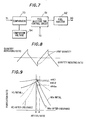
- Fig. 5 is a graph showing the exhaust amount of NOx and hydrocarbon in exhaust gas after passing through a three-way catalyst in a case of performing a correction by referring to an NOx sensor according to the present invention.
- Fig. 6 is a block diagram of one example of superimposing an output of an NOx sensor on an output of an oxygen sensor.
- Fig. 7 is a block diagram of one example of adding an output of an NOx sensor to a fuel injection time control circuit.
- Fig. 8 is a chart showing a control signal for fuel injection amount.
- Fig. 9 is a graph showing the initial and after-endurance purification rate characteristic of a three-way catalyst.
- Fig. 10 is a graph showing the correlation between the corrected voltage and the HC concentration under running conditions of constant speed, evaluated using a new three-way catalyst and five endurance level three-way catalysts.
- Fig. 11 is a graph showing the correlation between the corrected voltage and the HC exhaust amount in the FTP running mode, evaluated using a new three-way catalyst and five endurance level three-way catalysts.
- Fig. 12 is an explanatory view of the basic configuration of an NOx sensor according to the present invention.
- Fig. 13 is a graph showing the correlation between a value of pump current in a first electrochemical cell and the HC concentration under running conditions of constant speed, evaluated using a new three-way catalyst and five endurance level three-way catalysts.
- Fig. 14 is a graph showing the correlation between a value of pump current in a first electrochemical cell and the HC exhaust amount in the FTP running mode, evaluated using a new three-way catalyst and five endurance level three-way catalysts.
- Hereinafter, a method for controlling an engine exhaust gas system according to the present invention is described. A specific example of method for correcting a control point for air fuel ratio in accordance with an output of an NOx sensor and its advantages will be described in detail.
- Fig. 1 is an explanatory view showing an embodiment of a method for controlling an engine exhaust gas system according to the present invention. Fig. 2 is a block illustrative diagram showing an air-fuel ratio control circuit section of Fig. 1, and Fig. 3 is a circuit illustration of an air-fuel ratio control circuit section of Fig. 1.
- In Fig. 1, a three-
way catalyst 40 is provided at the exhaust gas system of anengine 30, while anoxygen sensor 71 and anitrogen oxide sensor 70 are provided upstream and downstream of the three-way catalyst 40, respectively. In this engine exhaust gas system, the air-fuel ratio of exhaust gas exhausted from theengine 30 is detected with theoxygen sensor 71 and is controlled near the stoichiometric air-fuel ratio with a closed loop control using the resultant signal. This exhaust gas is led to the three-way catalyst 40, from which harmful components such as nitrogen oxide (NOx), hydrocarbon (HC) and carbon monoxide (CO) are removed. - Here, as
oxygen sensor 71, a sensor comprising an oxygen concentration cell using a zirconia porcelain as solid electrolyte, an all range type sensor for determining a diffusion limiting current by an oxygen pump, a sensor according to a change in the resistance of an oxide semiconductor such as titania, or the like is available. AsNOx sensor 70, a sensor with an oxygen pump using the zirconia porcelain, e.g., described in European Patent Publication 0678740A1, as solid electrode, a sensor which measures a change in electromotive force being generated in an electrochemical cell with controlling an oxygen concentration by combining an oxygen pump and an electrochemical cell, a sensor according to a change in the resistance of an oxide semiconductor, a sensor for measuring a change in the resistance of an oxide semiconductor under control of oxygen concentration, comprising a combination of an oxygen pump and an oxide semiconductor, or the like is available. - With respect to an air-fuel ratio
control circuit section 50 and acontrol section 60 for fuel injection amount, one example thereof will be described referring to Figs. 2 and 3. - As shown in Figs. 2 and 3, a 0-5 V output signal of the NOx sensor (a sensor signal is so processed as to issue an output of 0-5 V for an NOx concentration of 0-2000 ppm) is compared with a comparison voltage (0.25 V) 53 corresponding to 100 ppm and superposed to the comparison voltage (0.4 V) of a comparator (comparative amplifier) 52 in an
oxygen sensor 71 by means of ancomparison amplifier 51 comprising a comparison voltage correction circuit. Thereby, the comparison voltage substantially ascends if the NOx concentration is greater than 100 ppm, an output in a lean condition of air-fuel ratio is issued from the air-fuel ratiocontrol circuit section 50 and transferred to the fuel jettime control circuit 61 of acontrol section 60 for fuel injection amount, so that the control point for air fuel ratio moves in the increasing direction of fuel injected from afuel injector 62 to anengine 30, e.g., in a decreasing direction of NOx. - By the adoption of this correction control, the NOx concentration is always controlled near 100 ppm, thereby eliminating a mass generation of NOx during the acceleration under FTP (Federal Test Procedure) running condition and reducing dispersion in the exhaust amount of NOx, HC and CO due to dispersion in the characteristic of an oxygen sensor.
- Figs. 4 and 5 are graphs the exhaust amount of NOx and hydrocarbon in exhaust gas after passing through a three-way catalyst for a case of using an air-fuel ratio control by a conventional oxygen sensor alone and for a case of performing a correction by an NOx sensor according to the present invention, respectively.
- In a case of using the air-fuel ratio control by a conventional oxygen sensor alone, as shown in Fig. 4, dispersion in the characteristic of an oxygen sensor and dispersion in the purification characteristic of a catalyst leads to large dispersion in the exhaust amount of NOx and hydrocarbon and further this dispersion increases due to a change with time during use. To satisfy the exhaust gas regulating value under conditions of large dispersion, using a large-sized catalyst or a great carrying amount of noble metal catalyst was necessary.
- In contrast, in a case where a correction by an NOx sensor according to the present invention is performed, since the concentration of exhausted NOx can be controlled independently of the characteristic of an oxygen sensor and the purification characteristic of a catalyst as shown in Fig. 5, the exhaust amount of NOx can be accurately controlled to a predetermined value. Thus, it is only necessary to set the catalyst to a necessary minimum size, and further because the control point for air-fuel ratio becomes accurate, the exhaust amounts of HC and CO are also reduced.
- Alternatively, as correction method for air fuel-ratio in accordance with an output of an NOx sensor, an output of the
NOx sensor 70 is superposed on an output of theoxygen sensor 71 with inverting a polarity in a sensorsignal correction circuit 72 and this correction signal may be compared with a comparison voltage (0.4V) 54 in acomparator 73 as shown in Fig. 6. Thereby, when the NOx concentration is more than 100 ppm, the output of the oxygen sensor substantially lowers and an output in a lean condition of air fuel-ratio is transferred to acontrol circuit 61 for fuel injection time, so that the control point for air fuel ratio moves in the increasing direction of fuel injected from afuel injector 62 into anengine 30, i.e., in the decreasing direction of NOx. - Furthermore, as shown in Fig. 7, there may be alternatively employed a method comprising the steps of comparing an output of the
oxygen sensor 71 with the comparison voltage (0.4V) 54 by acomparator 73, transferring the resultant signal to a fuel injectiontime control circuit 61 and moreover adding an output of anNOx sensor 70 to acontrol circuit 61 for fuel injection time to adjust the quantity increasing ratio, the quantity decreasing ratio, the jump amount, etc., of a control signal for fuel injection quantity shown in Fig. 8. - Incidentally, it is preferable in view of gas regulation measures to replace the NOx concentration information from an NOx sensor, gas flow rate information, and running speed information with NOx exhaust quantity (g/mile) information and correct the air-fuel ratio.
- Next, one embodiment of method for detecting the deterioration of a three-way catalyst and/or oxide sensor by referring to the extent of correction of the control point for air-fuel ratio of an oxygen sensor in accordance with an output of an NOx sensor according to the present invention and its advantages will be described.
- Fig. 9 is a graph showing the initial and after-endurance purification rate characteristics of a three-way catalyst. η NOx1 is a purification required to set the NOx concentration to 100 ppm under a predetermined running condition. When a three-way catalyst deteriorates with time, the purification rates of NOx and HC lower together. To maintain the NOx concentration at 100 ppm even after the endurance, the control point for air-fuel ratio moves from the point A to the point B and as a result, the purification rate of HC lowers from η HC1 to η HC2. Thus, the difference of correction signals A-B can be employed as a measure for representing the degree of deterioration of a three-way catalyst and for example, a change in the extent of correction signals and the exhaust amount of HC have correlation under running condition of a predetermined constant speed. The exhaust amount of HC is calculated from this correlation and the judgment of deterioration can be performed.
- Figs. 10 and 11 show the relations of a change in correction voltage with the HC concentration under running condition of constant speed and the HC exhaust amount in the FTP running mode measured using a new three-way catalyst and 5 endurance levels of three-way catalysts, both of which are found to have a good correlation.
- Next, a specific example of method for detecting the deterioration of a three-way catalyst and/or oxygen sensor by referring to a pumping current of the first electrochemical pump cell in an NOx sensor and its advantages will be described.
- An NOx sensor of scheme showing the basic configuration in Fig. 12 may be used. In Fig. 12, a first electrochemical pump cell 4 is constituted of a partition wall 1, an
inside pump electrode 2, and an outside pump electrode 3 such as platinum. Theelectrodes 2 and 3 are provided on both surfaces of a partition wall 1 made of oxygen ion conductive solid electrolyte such as zirconia porcelain. Between theinside pump electrode 2 and the outside pump electrode 3 of the first electrochemical pump cell 4, anelectric circuit 16 is provided, which main pumping means 17 is so arranged as to apply a control voltage from apower source 8 to. In this configuration, the measuring gas is introduced from the measuringgas space 6 into a first internal space 7 via a first diffusion controlledpassage 5. By a control voltage applied to between theinside pump electrode 2 and the outside pump electrode 3 from thepower source 8, the oxygen partial pressure in the first internal space 7 is controlled to a predetermined, preferable low value as does not allow NO to be reduced. - The atmosphere in an internal space 7 with this oxygen partial pressure is introduced into a second
internal space 10 via a second diffusion controlledpassage 9. In the secondinternal space 10, anelectric circuit 19 is provided between adetection electrode 11 and areference electrode 12 disposed on both surfaces of the partition wall 1, all of which constitute electric signal conversion means 18. And, on thedetection electrode 11, acatalyst 14 for accelerating the decomposition of NOx is provided. - Then, NOx in the atmosphere introduced into the second
internal space 10 via the second diffusion controlledpassage 9 is decomposed either by acatalyst 14 or under a low partial oxygen pressure, and at that time the generated oxygen is pumped out from the secondinternal space 10 to the reference gas existing space 6' by using a secondelectrochemical pump cell 13 under gas diffusion controlled conditions, and the NOx amount in the measuring gas is measured by referring to a value of current flowing through the secondelectrochemical pump cell 13. Incidentally, the secondelectrochemical pump cell 13 has only to detect the NOx concentration, and instead detectors of other schemes, e.g., oxide semiconductor whose resistance changes with different NOx concentrations. - As already described, the move amount of a control point for air-fuel ratio obtained when the NOx concentration after passing through a three-way catalyst is controlled to a predetermined value represents the degree of deterioration of the catalyst or an oxygen sensor. Accordingly, when this move amount reaches a predetermined value during monitoring, it can be judged that the catalyst has deteriorated.
- With an NOx sensor of the scheme of Fig. 12, the value of the first electrochemical pump cell current (first pump current value) is a value corresponding to the residual oxygen concentration after oxygen in the measuring gas has reacted with combustible gases such as HC. If this value deviates from a predetermined range, a value of HC in the exhaust gas after gas passing through a three-way catalyst never fails to exceed a predetermined range. That is, for an initial three-way catalyst, the air-fuel ratio is controlled at the point A (to the lean side from the stoichiometric air-fuel ratio point) as shown in Fig. 9 and the oxygen concentration in exhaust gas is high, and the amount of combustible gases such as HC is small. Consequently, first pump current representing the residual oxygen concentration after the reaction of oxygen with combustible gases such as HC becomes a large value. When the control point moves in the rich direction as a result of deterioration with time of a three-way catalyst (point B of Fig. 9), the oxygen concentration in exhaust gas lowers, whereas the amount of combustible gases such as HC increases. Because of corresponding to the residual oxygen concentration after the reaction of oxygen with combustible gases such as HC, first pump current greatly lowers on account of the additive effect of a change in oxygen and a change in combustible gases such as HC.
- Incidentally, a value of current for the judgment of deterioration may be represented in terms of absolute value or width of changes. Figs. 13 and 14 show the correlation of a value of pump current for a first electrochemical cell, i.e., the excessive oxygen amount with the HC concentration under running condition of constant speed and the HC exhaust amount in the FTP running mode measured using a new three-way catalyst and 5 endurance levels of three-way catalysts, both of which are found to have a good correlation.
- On an automobile with a 1-liter volume three-way catalyst attached to a 2-liter displacement and 4 cylinder gasoline engine, 5 different oxygen sensors A-E in characteristic and an NOx sensor of Fig. 12 were mounted as shown in Fig. 1, the air-fuel ratio was corrected in the circuits of Figs. 2 and 3 and the amounts of NOx and HC contained in exhaust gas were measured under conditions of the FTP driving mode.
- According to the results shown in Table 1, even when oxygen sensors vary in characteristic, both NOx and HC in all five types of oxygen sensors satisfy the LEV (Low Emission Vehicle) standard values for US California automobile exhaust gas regulation, NOx ≦ 0.20 g/mile and HC ≦ 0.075 g/mile, if correction for the air-fuel ratio according to a NOx sensor was made. In contrast, the sensor D and E did not satisfy the standard values if no correction made.
- Furthermore, in this automobile, oxygen sensors, a three-way catalyst and an NOx sensor were subjected to 50 kmile durability tests at the same time. As shown in Table 2, the results obtained revealed that all oxygen sensors satisfied the LEV after-endurance standard values, that NOx ≦ 0.20 g/mile and HC ≦ 0.075 g/mile, even if the characteristic of oxygen sensors or a catalyst deteriorates. In contrast, any one of the oxygen sensors did not satisfy the standard values if no correction made.
Oxygen sensor With correction control Without correction control NOx (g/mile) HC (g/mile) NOx (g/mile) HC (g/mile) A 0.16 0.04 0.18 0.04 B 0.17 0.04 0.15 0.05 C 0.16 0.05 0.13 0.06 D 0.16 0.05 0.10 0.08 E 0.17 0.04 0.08 0.12 Oxygen sensor With correction control Without correction control NOx (g/mile) HC (g/mile) NOx (g/mile) HC (g/mile) A 0.18 0.06 0.23 0.04 B 0.17 0.07 0.21 0.06 C 0.18 0.05 0.17 0.08 D 0.16 0.06 0.13 0.09 E 0.17 0.05 0.11 0.10 - As obvious from the above description, according to a method for controlling an engine exhaust gas system of the present invention, the harmful components in engine exhaust gas can be controlled to a low concentration for a long period of time and the deterioration of a three-way catalyst and oxygen sensors in an exhaust gas purification system can be surely detected, which is industrially very useful.
- The following numbered paragraphs set out inventive combinations of the features herein disclosed:-
- 1. A method for controlling an engine exhaust gas
system, comprising the steps of:
- detecting an air-fuel ratio of exhaust gas discharged from an internal engine by an oxygen sensor;
- controlling said exhaust gas to near the stoichiometric air-fuel ratio by a closed-loop control referring to a resultant signal; and
- leading said exhaust gas to a three-way catalyst to treat nitrogen oxide, hydrocarbon and carbon monoxide;
- wherein a nitrogen oxide sensor is provided downstream of said three-way catalyst; and
- a control value of air-fuel ratio by a closed loop control by said oxygen sensor is corrected to set the nitrogen oxide concentration to a predetermined value in accordance with an output of said nitrogen oxide sensor.
- 2. The method for controlling engine exhaust gas
systems as set forth in paragraph 1, wherein
said nitrogen oxide sensor comprises main pump means including an electrochemical pump cell comprising a substrate composed of oxygen ion conductive solid electrolyte, an inside pump electrode and an outside pump electrode formed on the inner surface and outer surface of the substrate, respectively, and the main pump means treating oxygen contained in the measuring gas introduced from an external space by pumping processing on the basis of a control voltage applied between the inside pump electrode and the outside pump electrode, and electric signal conversion means for generating an electric signal corresponding to the quantity of oxygen generated by decomposition or reduction of NOx contained in the measuring gas after treated by the pumping processing by the main pump means in which one side thereof has a pair of detection electrodes formed on the side where the measuring gas that was treated by pumping processing by the main pump means is introduced. - 3. The method for controlling engine exhaust gas
systems as set forth in paragraph 1 or
paragraph 2,
wherein the deterioration of a three-way catalyst and/or oxygen sensor is detected by comparing a change in control corrected value for the air-fuel ratio of closed loop control referring to an output of said nitrogen oxide sensor with a predetermined value. - 4. The method for controlling engine exhaust gas
systems as set forth in
paragraph 2, wherein the deterioration of a three-way catalyst and/or oxygen sensor is detected in accordance with a value or a change of pump current required for the pumping of oxygen in the electrochemical pump cell of said nitrogen oxide sensor. -
Claims (3)
- A method for controlling an engine exhaust gas system, comprising the steps of:detecting the air-fuel ratio of exhaust gas discharged from an internal engine by an oxygen sensor;controlling said exhaust gas to near the stoichiometric air-fuel ratio by a closed-loop control using the resultant signal; andleading said exhaust gas to a three-way catalyst to treat nitrogen oxides, hydrocarbon and carbon monoxide;wherein a nitrogen oxide sensor is provided downstream of said three-way catalyst; andthe nitrogen oxide concentration is set to a predetermined value by correcting a control value for air-fuel ratio by a closed loop control referring to a signal of said oxygen sensor in accordance with an output of said nitrogen oxide sensor, when in accordance with the extent of correction for the control value of an air-fuel ratio or the change width thereof, the deterioration of said three-way catalyst and/or said oxygen sensor is detected.
- The method for controlling an engine exhaust system as set forth in claim 1, wherein said nitrogen oxide sensor comprises main pump means including an electrochemical pump cell comprising a substrate composed of oxygen ion conductive solid electrolyte, an inside pump electrode and an outside pump electrode formed on the inner surface and outer surface of the substrate, respectively, and the main pump means treating oxygen contained in the measuring gas introduced from an external space by pumping processing on the basis of a control voltage applied between the inside pump electrode and the outside pump electrode, and electric signal conversion means for generating an electric signal corresponding to the quantity of oxygen generated by decomposition or reduction of NOx contained in the measuring gas after treated by the pumping processing by the main pump means in which one side thereof has a pair of detection electrodes formed on the side where the measuring gas that was treated by pumping processing by the main pump means is introduced.
- The method for controlling an engine exhaust gas system as set forth in claim 6, wherein the deterioration of a three-way catalyst and/or oxygen sensor is detected in accordance with a value or a change of pump current value required for the pumping of oxygen in the electrochemical pump cell of said nitrogen oxide sensor.
Applications Claiming Priority (5)
| Application Number | Priority Date | Filing Date | Title |
|---|---|---|---|
| JP16121896 | 1996-06-21 | ||
| JP16121896 | 1996-06-21 | ||
| JP9139021A JPH1068346A (en) | 1996-06-21 | 1997-05-28 | Control method for engine exhaust gas system |
| JP13902197 | 1997-05-28 | ||
| EP97304349A EP0814249B1 (en) | 1996-06-21 | 1997-06-20 | Method for controlling engine exhaust gas system |
Related Parent Applications (1)
| Application Number | Title | Priority Date | Filing Date |
|---|---|---|---|
| EP97304349A Division EP0814249B1 (en) | 1996-06-21 | 1997-06-20 | Method for controlling engine exhaust gas system |
Publications (3)
| Publication Number | Publication Date |
|---|---|
| EP1302648A2 true EP1302648A2 (en) | 2003-04-16 |
| EP1302648A3 EP1302648A3 (en) | 2005-04-27 |
| EP1302648B1 EP1302648B1 (en) | 2006-11-29 |
Family
ID=26471930
Family Applications (2)
| Application Number | Title | Priority Date | Filing Date |
|---|---|---|---|
| EP03000710A Expired - Lifetime EP1302648B1 (en) | 1996-06-21 | 1997-06-20 | Method for controlling engine exhaust gas system |
| EP97304349A Expired - Lifetime EP0814249B1 (en) | 1996-06-21 | 1997-06-20 | Method for controlling engine exhaust gas system |
Family Applications After (1)
| Application Number | Title | Priority Date | Filing Date |
|---|---|---|---|
| EP97304349A Expired - Lifetime EP0814249B1 (en) | 1996-06-21 | 1997-06-20 | Method for controlling engine exhaust gas system |
Country Status (4)
| Country | Link |
|---|---|
| US (1) | US6012282A (en) |
| EP (2) | EP1302648B1 (en) |
| JP (1) | JPH1068346A (en) |
| DE (2) | DE69736795T2 (en) |
Families Citing this family (69)
| Publication number | Priority date | Publication date | Assignee | Title |
|---|---|---|---|---|
| US6309536B1 (en) * | 1997-10-14 | 2001-10-30 | Ngk Spark Plug Co., Ltd. | Method and apparatus for detecting a functional condition on an NOx occlusion catalyst |
| JP3456401B2 (en) * | 1998-02-12 | 2003-10-14 | 日産自動車株式会社 | Exhaust gas purification device for internal combustion engine |
| DE19819204C1 (en) * | 1998-04-29 | 1999-09-30 | Siemens Ag | Trimming two-point exhaust gas sensor indication, to compensate behavioral shift due to aging and poisoning |
| DE19828928C2 (en) * | 1998-06-29 | 2003-04-17 | Siemens Ag | Method for monitoring the exhaust gas purification system of an internal combustion engine |
| DE19830829C1 (en) * | 1998-07-09 | 1999-04-08 | Siemens Ag | NOX storage catalyst regeneration process |
| DE19852244C1 (en) * | 1998-11-12 | 1999-12-30 | Siemens Ag | Controlling NOx emission in exhaust gases passing through three-way catalyst followed by lambda sensor |
| JP3607976B2 (en) | 1999-03-29 | 2005-01-05 | トヨタ自動車株式会社 | Exhaust gas purification device for internal combustion engine |
| EP1196681B1 (en) * | 1999-05-19 | 2003-09-17 | Robert Bosch Gmbh | Method for controlling a rich/lean combustion mixture in a defined manner |
| JP2000352307A (en) * | 1999-06-10 | 2000-12-19 | Hitachi Ltd | Engine emission control system |
| DE19931321A1 (en) * | 1999-07-07 | 2001-01-18 | Siemens Ag | Method for checking a three-way catalytic converter of an internal combustion engine |
| DE19953601C2 (en) * | 1999-11-08 | 2002-07-11 | Siemens Ag | Method for checking an exhaust gas catalytic converter of an internal combustion engine |
| JP3782269B2 (en) * | 1999-11-12 | 2006-06-07 | 本田技研工業株式会社 | Air-fuel ratio control device for internal combustion engine |
| JP3688533B2 (en) * | 1999-11-12 | 2005-08-31 | 本田技研工業株式会社 | Degradation state evaluation method of exhaust gas purification catalyst device |
| US6860100B1 (en) * | 2000-03-17 | 2005-03-01 | Ford Global Technologies, Llc | Degradation detection method for an engine having a NOx sensor |
| US6360530B1 (en) | 2000-03-17 | 2002-03-26 | Ford Global Technologies, Inc. | Method and apparatus for measuring lean-burn engine emissions |
| US6427437B1 (en) * | 2000-03-17 | 2002-08-06 | Ford Global Technologies, Inc. | Method for improved performance of an engine emission control system |
| US6487850B1 (en) * | 2000-03-17 | 2002-12-03 | Ford Global Technologies, Inc. | Method for improved engine control |
| US6810659B1 (en) * | 2000-03-17 | 2004-11-02 | Ford Global Technologies, Llc | Method for determining emission control system operability |
| US6434930B1 (en) * | 2000-03-17 | 2002-08-20 | Ford Global Technologies, Inc. | Method and apparatus for controlling lean operation of an internal combustion engine |
| DE10014239A1 (en) * | 2000-03-22 | 2001-10-31 | Volkswagen Ag | Monitoring the function of a three-way catalyst in the exhaust gas channel of IC engine comprises acquiring the size of the nitrogen oxides signal within the lambda region, and comparing with threshold values |
| US6347512B1 (en) * | 2000-04-28 | 2002-02-19 | Ford Global Technologies, Inc. | Method and system for controlling a lean NOx trap purge cycle |
| US6363715B1 (en) * | 2000-05-02 | 2002-04-02 | Ford Global Technologies, Inc. | Air/fuel ratio control responsive to catalyst window locator |
| US6360159B1 (en) * | 2000-06-07 | 2002-03-19 | Cummins, Inc. | Emission control in an automotive engine |
| US6427439B1 (en) * | 2000-07-13 | 2002-08-06 | Ford Global Technologies, Inc. | Method and system for NOx reduction |
| US6389803B1 (en) * | 2000-08-02 | 2002-05-21 | Ford Global Technologies, Inc. | Emission control for improved vehicle performance |
| US6849239B2 (en) | 2000-10-16 | 2005-02-01 | E. I. Du Pont De Nemours And Company | Method and apparatus for analyzing mixtures of gases |
| JP2004523731A (en) | 2000-10-16 | 2004-08-05 | イー・アイ・デュポン・ドウ・ヌムール・アンド・カンパニー | Method and apparatus for analyzing a mixture of gases |
| DE60124953T2 (en) | 2000-10-16 | 2007-09-20 | E.I. Du Pont De Nemours And Co., Wilmington | INFRARED THERMOGRAPHIC PROCEDURE FOR SEMICONDUCTOR SEMICONDUCTORS |
| US20020192293A1 (en) * | 2001-04-06 | 2002-12-19 | Gadiraju Srinivas R. | Method for manufacture of extended release dosage form |
| US7765794B2 (en) * | 2001-05-04 | 2010-08-03 | Nco2 Company Llc | Method and system for obtaining exhaust gas for use in augmenting crude oil production |
| US6712604B2 (en) * | 2001-06-15 | 2004-03-30 | Honeywell International Inc. | Cautious optimization strategy for emission reduction |
| US6463733B1 (en) | 2001-06-19 | 2002-10-15 | Ford Global Technologies, Inc. | Method and system for optimizing open-loop fill and purge times for an emission control device |
| US6487853B1 (en) | 2001-06-19 | 2002-12-03 | Ford Global Technologies. Inc. | Method and system for reducing lean-burn vehicle emissions using a downstream reductant sensor |
| US6604504B2 (en) | 2001-06-19 | 2003-08-12 | Ford Global Technologies, Llc | Method and system for transitioning between lean and stoichiometric operation of a lean-burn engine |
| US6467259B1 (en) | 2001-06-19 | 2002-10-22 | Ford Global Technologies, Inc. | Method and system for operating dual-exhaust engine |
| US6694244B2 (en) | 2001-06-19 | 2004-02-17 | Ford Global Technologies, Llc | Method for quantifying oxygen stored in a vehicle emission control device |
| US6539706B2 (en) | 2001-06-19 | 2003-04-01 | Ford Global Technologies, Inc. | Method and system for preconditioning an emission control device for operation about stoichiometry |
| US6553754B2 (en) | 2001-06-19 | 2003-04-29 | Ford Global Technologies, Inc. | Method and system for controlling an emission control device based on depletion of device storage capacity |
| US6502387B1 (en) | 2001-06-19 | 2003-01-07 | Ford Global Technologies, Inc. | Method and system for controlling storage and release of exhaust gas constituents in an emission control device |
| US6453666B1 (en) | 2001-06-19 | 2002-09-24 | Ford Global Technologies, Inc. | Method and system for reducing vehicle tailpipe emissions when operating lean |
| US6615577B2 (en) | 2001-06-19 | 2003-09-09 | Ford Global Technologies, Llc | Method and system for controlling a regeneration cycle of an emission control device |
| US6546718B2 (en) | 2001-06-19 | 2003-04-15 | Ford Global Technologies, Inc. | Method and system for reducing vehicle emissions using a sensor downstream of an emission control device |
| US6594985B2 (en) * | 2001-06-19 | 2003-07-22 | Ford Global Technologies, Inc. | Exhaust gas aftertreatment device efficiency estimation |
| US6650991B2 (en) | 2001-06-19 | 2003-11-18 | Ford Global Technologies, Llc | Closed-loop method and system for purging a vehicle emission control |
| US6691020B2 (en) | 2001-06-19 | 2004-02-10 | Ford Global Technologies, Llc | Method and system for optimizing purge of exhaust gas constituent stored in an emission control device |
| US6490860B1 (en) | 2001-06-19 | 2002-12-10 | Ford Global Technologies, Inc. | Open-loop method and system for controlling the storage and release cycles of an emission control device |
| US6453663B1 (en) | 2001-08-16 | 2002-09-24 | Ford Global Technologies, Inc | NOx sensor monitoring |
| DE10211781B4 (en) * | 2002-03-16 | 2004-08-12 | Innecken Elektrotechnik Gmbh & Co. Kg | Method and device for monitoring and regulating the operation of an internal combustion engine with reduced NOx emissions |
| US7575931B2 (en) * | 2002-06-19 | 2009-08-18 | E.I. Du Pont De Nemours And Company | Method and apparatus for reducing a nitrogen oxide, and control thereof |
| US20040126286A1 (en) * | 2002-06-19 | 2004-07-01 | Deruyter John C. | Method and apparatus for reducing a nitrogen oxide |
| US6701707B1 (en) | 2002-09-04 | 2004-03-09 | Ford Global Technologies, Llc | Exhaust emission diagnostics |
| US7134273B2 (en) | 2002-09-04 | 2006-11-14 | Ford Global Technologies, Llc | Exhaust emission control and diagnostics |
| JP3912294B2 (en) * | 2003-02-19 | 2007-05-09 | トヨタ自動車株式会社 | Exhaust gas purification method and exhaust gas purification apparatus for internal combustion engine |
| US7460958B2 (en) * | 2004-10-07 | 2008-12-02 | E.I. Du Pont De Nemours And Company | Computer-implemented system and method for analyzing mixtures of gases |
| US8236246B2 (en) * | 2004-10-07 | 2012-08-07 | E I Du Pont De Nemours And Company | Gas sensitive apparatus |
| US7644576B2 (en) * | 2005-04-25 | 2010-01-12 | Ngk Spark Plug Co., Ltd. | Sensor control device |
| JP4779721B2 (en) * | 2006-03-10 | 2011-09-28 | 株式会社日立製作所 | Engine system |
| US7255098B1 (en) | 2006-04-27 | 2007-08-14 | Caterpillar Inc. | Engine emissions control system |
| JP4665923B2 (en) | 2007-03-13 | 2011-04-06 | トヨタ自動車株式会社 | Catalyst deterioration judgment device |
| DE112007003414B4 (en) * | 2007-04-26 | 2020-02-06 | FEV Europe GmbH | Regulation of a motor vehicle internal combustion engine |
| JP4492669B2 (en) * | 2007-10-24 | 2010-06-30 | トヨタ自動車株式会社 | Air-fuel ratio control device for internal combustion engine |
| US8887490B2 (en) * | 2013-02-06 | 2014-11-18 | General Electric Company | Rich burn internal combustion engine catalyst control |
| JP6128041B2 (en) * | 2014-03-31 | 2017-05-17 | トヨタ自動車株式会社 | Internal combustion engine control system |
| JP6144652B2 (en) * | 2014-07-23 | 2017-06-07 | トヨタ自動車株式会社 | Exhaust gas purification device for internal combustion engine |
| US10760466B2 (en) | 2016-03-24 | 2020-09-01 | Kerdea Technologies, Inc. | Resistive based NOx sensing method and apparatus |
| JP2020070769A (en) | 2018-11-01 | 2020-05-07 | マツダ株式会社 | Control device for engine |
| JP2020070770A (en) | 2018-11-01 | 2020-05-07 | マツダ株式会社 | Control device for engine |
| JP7137146B2 (en) | 2019-01-28 | 2022-09-14 | マツダ株式会社 | engine controller |
| CN113804825A (en) * | 2020-06-12 | 2021-12-17 | 卓品智能科技无锡有限公司 | Multichannel parallel automatic calibration method and system for vehicle-mounted nitrogen-oxygen sensor |
Citations (8)
| Publication number | Priority date | Publication date | Assignee | Title |
|---|---|---|---|---|
| US4770760A (en) * | 1986-08-04 | 1988-09-13 | Ngk Insulators, Ltd. | Electrochemical NOx sensor |
| EP0308870A2 (en) * | 1987-09-22 | 1989-03-29 | Japan Electronic Control Systems Co., Ltd. | Electronic air-fuel ratio control apparatus in internal combustion engine |
| JPH02125941A (en) * | 1988-11-05 | 1990-05-14 | Nippon Denso Co Ltd | Air-fuel ratio control device of engine |
| JPH0373839A (en) * | 1989-08-15 | 1991-03-28 | Nissan Motor Co Ltd | Deterioration detector for catalyst |
| JPH04359144A (en) * | 1991-06-04 | 1992-12-11 | Mitsubishi Motors Corp | Nox sensor |
| US5303580A (en) * | 1991-04-17 | 1994-04-19 | Robert Bosch Gmbh | Method and arrangement for determining the state of deterioration of a catalyzer |
| US5426934A (en) * | 1993-02-10 | 1995-06-27 | Hitachi America, Ltd. | Engine and emission monitoring and control system utilizing gas sensors |
| US5452576A (en) * | 1994-08-09 | 1995-09-26 | Ford Motor Company | Air/fuel control with on-board emission measurement |
Family Cites Families (9)
| Publication number | Priority date | Publication date | Assignee | Title |
|---|---|---|---|---|
| JPS57168040A (en) * | 1981-04-10 | 1982-10-16 | Nippon Kokan Kk <Nkk> | Method to determine combustion condition of diesel engine |
| JPS5951150A (en) * | 1982-09-16 | 1984-03-24 | Nissan Motor Co Ltd | Control of idle revolution speed of internal-combustion engine |
| JP2636883B2 (en) * | 1988-04-30 | 1997-07-30 | 日本碍子株式会社 | NOx concentration measuring device |
| JPH0715272B2 (en) * | 1989-04-28 | 1995-02-22 | 日産自動車株式会社 | Air-fuel ratio controller for internal combustion engine |
| JP3018040B2 (en) * | 1990-05-11 | 2000-03-13 | セイコー精機株式会社 | Hard disk inspection device |
| JP2943261B2 (en) * | 1990-07-06 | 1999-08-30 | 石川島播磨重工業株式会社 | Method of forming rod-shaped part by FRP |
| US5444974A (en) * | 1993-07-09 | 1995-08-29 | General Motors Corporation | On-board automotive exhaust catalyst monitoring with a calorimetric sensor |
| US5397442A (en) * | 1994-03-09 | 1995-03-14 | Gas Research Institute | Sensor and method for accurately measuring concentrations of oxide compounds in gas mixtures |
| JP2885336B2 (en) * | 1994-04-21 | 1999-04-19 | 日本碍子株式会社 | Method and apparatus for measuring NOx concentration in gas to be measured |
-
1997
- 1997-05-28 JP JP9139021A patent/JPH1068346A/en active Pending
- 1997-06-16 US US08/876,396 patent/US6012282A/en not_active Expired - Lifetime
- 1997-06-20 EP EP03000710A patent/EP1302648B1/en not_active Expired - Lifetime
- 1997-06-20 EP EP97304349A patent/EP0814249B1/en not_active Expired - Lifetime
- 1997-06-20 DE DE69736795T patent/DE69736795T2/en not_active Expired - Lifetime
- 1997-06-20 DE DE69737043T patent/DE69737043T2/en not_active Expired - Lifetime
Patent Citations (8)
| Publication number | Priority date | Publication date | Assignee | Title |
|---|---|---|---|---|
| US4770760A (en) * | 1986-08-04 | 1988-09-13 | Ngk Insulators, Ltd. | Electrochemical NOx sensor |
| EP0308870A2 (en) * | 1987-09-22 | 1989-03-29 | Japan Electronic Control Systems Co., Ltd. | Electronic air-fuel ratio control apparatus in internal combustion engine |
| JPH02125941A (en) * | 1988-11-05 | 1990-05-14 | Nippon Denso Co Ltd | Air-fuel ratio control device of engine |
| JPH0373839A (en) * | 1989-08-15 | 1991-03-28 | Nissan Motor Co Ltd | Deterioration detector for catalyst |
| US5303580A (en) * | 1991-04-17 | 1994-04-19 | Robert Bosch Gmbh | Method and arrangement for determining the state of deterioration of a catalyzer |
| JPH04359144A (en) * | 1991-06-04 | 1992-12-11 | Mitsubishi Motors Corp | Nox sensor |
| US5426934A (en) * | 1993-02-10 | 1995-06-27 | Hitachi America, Ltd. | Engine and emission monitoring and control system utilizing gas sensors |
| US5452576A (en) * | 1994-08-09 | 1995-09-26 | Ford Motor Company | Air/fuel control with on-board emission measurement |
Non-Patent Citations (3)
| Title |
|---|
| PATENT ABSTRACTS OF JAPAN vol. 014, no. 357 (M-1005), 2 August 1990 (1990-08-02) & JP 02 125941 A (NIPPON DENSO CO LTD), 14 May 1990 (1990-05-14) * |
| PATENT ABSTRACTS OF JAPAN vol. 015, no. 237 (P-1216), 19 June 1991 (1991-06-19) & JP 03 073839 A (NISSAN MOTOR CO LTD), 28 March 1991 (1991-03-28) * |
| PATENT ABSTRACTS OF JAPAN vol. 017, no. 231 (P-1532), 11 May 1993 (1993-05-11) & JP 04 359144 A (MITSUBISHI MOTORS CORP), 11 December 1992 (1992-12-11) * |
Also Published As
| Publication number | Publication date |
|---|---|
| DE69736795T2 (en) | 2007-08-09 |
| EP0814249A2 (en) | 1997-12-29 |
| DE69736795D1 (en) | 2006-11-23 |
| JPH1068346A (en) | 1998-03-10 |
| EP1302648A3 (en) | 2005-04-27 |
| DE69737043T2 (en) | 2007-06-21 |
| EP1302648B1 (en) | 2006-11-29 |
| DE69737043D1 (en) | 2007-01-11 |
| EP0814249B1 (en) | 2006-10-11 |
| US6012282A (en) | 2000-01-11 |
| EP0814249A3 (en) | 2000-02-23 |
Similar Documents
| Publication | Publication Date | Title |
|---|---|---|
| US6012282A (en) | Method for controlling engine exhaust gas system | |
| US6408617B1 (en) | Diagnostic equipment for an exhaust gas cleaning apparatus | |
| US7744740B2 (en) | Procedure to recognize the diffusion gas composition in a wideband lambda sensor | |
| US5953907A (en) | Method of controlling an engine exhaust gas system and method of detecting deterioration of catalyst/adsorbing means | |
| US6442998B2 (en) | Gas concentration measuring apparatus compensating for error component of output signal | |
| US7409822B2 (en) | Exhaust gas control apparatus and exhaust gas control method for internal combustion engine | |
| JP4005273B2 (en) | Gas concentration detector | |
| US20040221641A1 (en) | Fault detecting apparatus designed to detect different types of faults of gas sensor | |
| US6901785B2 (en) | Gas concentration measuring apparatus designed to minimize measurement error | |
| US6895800B2 (en) | Gas concentration measuring apparatus minimizing measurement error | |
| WO2005121516A1 (en) | Exhaust gas control apparatus for internal combustion engine | |
| US11530665B2 (en) | Deterioration determination apparatus for ammonia sensor | |
| US7427347B2 (en) | Method for operating a measuring probe for measuring a gas concentration | |
| EP0444674A2 (en) | Air fuel ratio detecting device | |
| JP4325368B2 (en) | Air-fuel ratio measuring device | |
| JP2005504292A (en) | Method and circuit for operating a nitrogen oxide sensor | |
| US20210054796A1 (en) | Operation control method of vehicle engine and vehicle system | |
| US10865725B2 (en) | Exhaust system for internal combustion engine | |
| KR100212902B1 (en) | Air fuel ratio compensation method of abnormal oxygen sensor signal |
Legal Events
| Date | Code | Title | Description |
|---|---|---|---|
| PUAI | Public reference made under article 153(3) epc to a published international application that has entered the european phase |
Free format text: ORIGINAL CODE: 0009012 |
|
| AC | Divisional application: reference to earlier application |
Ref document number: 0814249 Country of ref document: EP Kind code of ref document: P |
|
| AK | Designated contracting states |
Designated state(s): DE FR GB IT SE |
|
| RIN1 | Information on inventor provided before grant (corrected) |
Inventor name: KATO, NOBUHIDE Inventor name: KURACHI, HIROSHIC/O NGK INSULATORS LTD. |
|
| PUAL | Search report despatched |
Free format text: ORIGINAL CODE: 0009013 |
|
| AK | Designated contracting states |
Kind code of ref document: A3 Designated state(s): DE FR GB IT SE |
|
| RIC1 | Information provided on ipc code assigned before grant |
Ipc: 7G 01N 27/406 B Ipc: 7F 02D 41/14 A Ipc: 7G 01N 27/419 B Ipc: 7F 02D 41/02 B Ipc: 7F 02D 41/22 B |
|
| 17P | Request for examination filed |
Effective date: 20050513 |
|
| AKX | Designation fees paid |
Designated state(s): DE FR GB IT SE |
|
| GRAP | Despatch of communication of intention to grant a patent |
Free format text: ORIGINAL CODE: EPIDOSNIGR1 |
|
| GRAJ | Information related to disapproval of communication of intention to grant by the applicant or resumption of examination proceedings by the epo deleted |
Free format text: ORIGINAL CODE: EPIDOSDIGR1 |
|
| GRAP | Despatch of communication of intention to grant a patent |
Free format text: ORIGINAL CODE: EPIDOSNIGR1 |
|
| GRAS | Grant fee paid |
Free format text: ORIGINAL CODE: EPIDOSNIGR3 |
|
| GRAA | (expected) grant |
Free format text: ORIGINAL CODE: 0009210 |
|
| AC | Divisional application: reference to earlier application |
Ref document number: 0814249 Country of ref document: EP Kind code of ref document: P |
|
| AK | Designated contracting states |
Kind code of ref document: B1 Designated state(s): DE FR GB IT SE |
|
| REG | Reference to a national code |
Ref country code: GB Ref legal event code: FG4D |
|
| REF | Corresponds to: |
Ref document number: 69737043 Country of ref document: DE Date of ref document: 20070111 Kind code of ref document: P |
|
| REG | Reference to a national code |
Ref country code: SE Ref legal event code: TRGR |
|
| ET | Fr: translation filed | ||
| PLBE | No opposition filed within time limit |
Free format text: ORIGINAL CODE: 0009261 |
|
| STAA | Information on the status of an ep patent application or granted ep patent |
Free format text: STATUS: NO OPPOSITION FILED WITHIN TIME LIMIT |
|
| 26N | No opposition filed |
Effective date: 20070830 |
|
| PGFP | Annual fee paid to national office [announced via postgrant information from national office to epo] |
Ref country code: GB Payment date: 20140618 Year of fee payment: 18 |
|
| PGFP | Annual fee paid to national office [announced via postgrant information from national office to epo] |
Ref country code: IT Payment date: 20140508 Year of fee payment: 18 Ref country code: SE Payment date: 20140611 Year of fee payment: 18 |
|
| PGFP | Annual fee paid to national office [announced via postgrant information from national office to epo] |
Ref country code: FR Payment date: 20140609 Year of fee payment: 18 |
|
| PG25 | Lapsed in a contracting state [announced via postgrant information from national office to epo] |
Ref country code: IT Free format text: LAPSE BECAUSE OF NON-PAYMENT OF DUE FEES Effective date: 20150620 |
|
| REG | Reference to a national code |
Ref country code: SE Ref legal event code: EUG |
|
| GBPC | Gb: european patent ceased through non-payment of renewal fee |
Effective date: 20150620 |
|
| PG25 | Lapsed in a contracting state [announced via postgrant information from national office to epo] |
Ref country code: SE Free format text: LAPSE BECAUSE OF NON-PAYMENT OF DUE FEES Effective date: 20150621 |
|
| REG | Reference to a national code |
Ref country code: FR Ref legal event code: ST Effective date: 20160229 |
|
| PG25 | Lapsed in a contracting state [announced via postgrant information from national office to epo] |
Ref country code: GB Free format text: LAPSE BECAUSE OF NON-PAYMENT OF DUE FEES Effective date: 20150620 |
|
| PG25 | Lapsed in a contracting state [announced via postgrant information from national office to epo] |
Ref country code: FR Free format text: LAPSE BECAUSE OF NON-PAYMENT OF DUE FEES Effective date: 20150630 |
|
| PGFP | Annual fee paid to national office [announced via postgrant information from national office to epo] |
Ref country code: DE Payment date: 20160614 Year of fee payment: 20 |
|
| REG | Reference to a national code |
Ref country code: DE Ref legal event code: R071 Ref document number: 69737043 Country of ref document: DE |