EP1306054B1 - A device for examining a subject capable of marking a boundary range for the insertion/retraction of a member - Google Patents
A device for examining a subject capable of marking a boundary range for the insertion/retraction of a member Download PDFInfo
- Publication number
- EP1306054B1 EP1306054B1 EP02023670A EP02023670A EP1306054B1 EP 1306054 B1 EP1306054 B1 EP 1306054B1 EP 02023670 A EP02023670 A EP 02023670A EP 02023670 A EP02023670 A EP 02023670A EP 1306054 B1 EP1306054 B1 EP 1306054B1
- Authority
- EP
- European Patent Office
- Prior art keywords
- retraction
- section
- ultrasound
- image
- biopsy
- Prior art date
- Legal status (The legal status is an assumption and is not a legal conclusion. Google has not performed a legal analysis and makes no representation as to the accuracy of the status listed.)
- Expired - Lifetime
Links
- 238000003780 insertion Methods 0.000 title claims description 110
- 230000037431 insertion Effects 0.000 title claims description 110
- 238000002604 ultrasonography Methods 0.000 claims description 175
- 238000012545 processing Methods 0.000 claims description 44
- 238000001514 detection method Methods 0.000 claims description 37
- 230000017531 blood circulation Effects 0.000 claims description 18
- 239000003550 marker Substances 0.000 claims description 10
- 230000004075 alteration Effects 0.000 claims description 5
- 238000001574 biopsy Methods 0.000 description 206
- 238000010276 construction Methods 0.000 description 17
- 239000000523 sample Substances 0.000 description 17
- 238000010586 diagram Methods 0.000 description 13
- 238000000034 method Methods 0.000 description 13
- 230000007246 mechanism Effects 0.000 description 12
- 230000006870 function Effects 0.000 description 9
- 230000015572 biosynthetic process Effects 0.000 description 6
- 230000000694 effects Effects 0.000 description 6
- 238000003786 synthesis reaction Methods 0.000 description 6
- 230000000007 visual effect Effects 0.000 description 5
- 230000005540 biological transmission Effects 0.000 description 3
- 238000013459 approach Methods 0.000 description 2
- 230000008901 benefit Effects 0.000 description 2
- 230000008569 process Effects 0.000 description 2
- 238000000926 separation method Methods 0.000 description 2
- 238000012285 ultrasound imaging Methods 0.000 description 2
- 208000007536 Thrombosis Diseases 0.000 description 1
- 210000004204 blood vessel Anatomy 0.000 description 1
- 210000001124 body fluid Anatomy 0.000 description 1
- 239000010839 body fluid Substances 0.000 description 1
- 230000008859 change Effects 0.000 description 1
- 230000001419 dependent effect Effects 0.000 description 1
- 238000002592 echocardiography Methods 0.000 description 1
- 238000011156 evaluation Methods 0.000 description 1
- 230000005389 magnetism Effects 0.000 description 1
- 238000012986 modification Methods 0.000 description 1
- 230000004048 modification Effects 0.000 description 1
Images


Classifications
-
- A—HUMAN NECESSITIES
- A61—MEDICAL OR VETERINARY SCIENCE; HYGIENE
- A61B—DIAGNOSIS; SURGERY; IDENTIFICATION
- A61B10/00—Other methods or instruments for diagnosis, e.g. instruments for taking a cell sample, for biopsy, for vaccination diagnosis; Sex determination; Ovulation-period determination; Throat striking implements
- A61B10/02—Instruments for taking cell samples or for biopsy
- A61B10/04—Endoscopic instruments
-
- A—HUMAN NECESSITIES
- A61—MEDICAL OR VETERINARY SCIENCE; HYGIENE
- A61B—DIAGNOSIS; SURGERY; IDENTIFICATION
- A61B8/00—Diagnosis using ultrasonic, sonic or infrasonic waves
- A61B8/08—Detecting organic movements or changes, e.g. tumours, cysts, swellings
- A61B8/0833—Detecting organic movements or changes, e.g. tumours, cysts, swellings involving detecting or locating foreign bodies or organic structures
- A61B8/0841—Detecting organic movements or changes, e.g. tumours, cysts, swellings involving detecting or locating foreign bodies or organic structures for locating instruments
-
- A—HUMAN NECESSITIES
- A61—MEDICAL OR VETERINARY SCIENCE; HYGIENE
- A61B—DIAGNOSIS; SURGERY; IDENTIFICATION
- A61B8/00—Diagnosis using ultrasonic, sonic or infrasonic waves
- A61B8/12—Diagnosis using ultrasonic, sonic or infrasonic waves in body cavities or body tracts, e.g. by using catheters
-
- A—HUMAN NECESSITIES
- A61—MEDICAL OR VETERINARY SCIENCE; HYGIENE
- A61B—DIAGNOSIS; SURGERY; IDENTIFICATION
- A61B10/00—Other methods or instruments for diagnosis, e.g. instruments for taking a cell sample, for biopsy, for vaccination diagnosis; Sex determination; Ovulation-period determination; Throat striking implements
- A61B10/02—Instruments for taking cell samples or for biopsy
- A61B10/04—Endoscopic instruments
- A61B2010/045—Needles
-
- A—HUMAN NECESSITIES
- A61—MEDICAL OR VETERINARY SCIENCE; HYGIENE
- A61B—DIAGNOSIS; SURGERY; IDENTIFICATION
- A61B17/00—Surgical instruments, devices or methods, e.g. tourniquets
- A61B17/34—Trocars; Puncturing needles
- A61B17/3403—Needle locating or guiding means
- A61B2017/3413—Needle locating or guiding means guided by ultrasound
-
- A—HUMAN NECESSITIES
- A61—MEDICAL OR VETERINARY SCIENCE; HYGIENE
- A61B—DIAGNOSIS; SURGERY; IDENTIFICATION
- A61B90/00—Instruments, implements or accessories specially adapted for surgery or diagnosis and not covered by any of the groups A61B1/00 - A61B50/00, e.g. for luxation treatment or for protecting wound edges
- A61B90/36—Image-producing devices or illumination devices not otherwise provided for
- A61B90/37—Surgical systems with images on a monitor during operation
- A61B2090/378—Surgical systems with images on a monitor during operation using ultrasound
- A61B2090/3782—Surgical systems with images on a monitor during operation using ultrasound transmitter or receiver in catheter or minimal invasive instrument
- A61B2090/3784—Surgical systems with images on a monitor during operation using ultrasound transmitter or receiver in catheter or minimal invasive instrument both receiver and transmitter being in the instrument or receiver being also transmitter
Definitions
- the present invention relates to an ultrasound diagnostic device capable of obtaining an ultrasound diagnostic image by performing transmission/reception of ultrasound signals with respect to a subject in a body cavity and piercing the subject with a biopsy needle.
- a typical ultrasound diagnostic device chiefly comprises an ultrasound probe that transmits and receives ultrasound in respect of a part to be examined within the body and the main ultrasound device unit that is connected with the probe.
- a biopsy needle when extracting body fluids or cells of a subject constituted by a part to be observed, a biopsy needle is employed to pierce the subject.
- the biopsy needle is mounted on an adaptor which is freely detachably mounted on the probe.
- the allowable error of the direction in which the biopsy needle is to be inserted is displayed by two lines when the part where biopsy is to be performed is specified.
- the operator can easily perform biopsy when the biopsy needle is inserted arranged in a direction coincident with the set biopsy guide.
- Japanese Laid-open Patent Application No. H8-299344 discloses an ultrasound diagnostic device wherein the direction of display of the biopsy guide is made to coincide with the angle of insertion of the biopsy needle.
- Japanese Laid-open Patent Application No. H8-229042 and Japanese Laid-open Patent Application No. H9-271472 disclose a technique in which the position of the tip of the biopsy needle is detected and displayed on an ultrasound tomogram.
- United States Patent No. 6,216,029 also discloses a method and system for guiding a needle being inserted into a patient using external ultrasound imaging. This method displays a trajectory for the needle.
- United States Patent No. 6,019,724 discloses a surgical device incorporating an endoscope having an ultrasound probe at a distal tip that generates a narrow ultrasound scan plane designed to identify the position of a surgical tool when it crosses or intersects the scan plane.
- United States Patent No. 4,763,662 discloses an ultrasonic .diagnostic apparatus comprising an endoscope having an ultrasonic probe at a distal end of the endoscope with which the insertion of a puncture needle into a diseased part can be observed.
- Japanese Patent Application Publication No. 09-103433 discloses an auxiliary tool for insertion and retraction of a piercing needle through an endoscope.
- United States Patent No. 4,671,292 describes an ultrasound imaging probe suitable for concentric on-axis biopsy procedures.
- it concerns an external ultrasound probe having a central axial aperture through which a biopsy needle is inserted for movement in one dimension, namely along the central axis defined by the aperture.
- An object of the present invention is to provide an ultrasound diagnostic device whereby ease and confidence in performing a piercing operation, e.g. during a biopsy, can be improved by displaying the boundary of the piercing direction of the biopsy needle.
- the present invention provides an ultrasound diagnostic device having the features recited in claim 1. Preferred features of the invention are recited in the dependent claims.
- An ultrasound diagnostic device for examining a subject within a body cavity comprises an ultrasound endoscope having an ultrasound image capture section capable of acquiring an ultrasound image of a subject and an insertion/retraction section mounted on an operating section of the endoscope, an insertion/retraction member provided through a section of the endoscope for insertion into the body cavity and having a desired positional relationship with the image capture section and capable of being freely inserted/retracted with respect to the subject by means of the invention/retraction section an insertion/retraction direction alteration section for adjusting the direction of insertion/retraction of the insertion/retraction member, and an image generating section that generates an image comprising an image of the subject acquired by the image capture section and an image of the insertion/retraction member.
- the ultrasound diagnostic device is characterized by a boundary position superimposition section that superimposes an insertion/retraction boundary marker indicating the position of an insertion/retraction boundary of the insertion/retraction member in the image generated by the image generating section wherein the insertion/retraction boundary marker comprises at least an insertion/retraction direction boundary marker indicating the boundary of the direction of insertion or retraction of the insertion/retraction member adjusted by the insertion/retraction direction alteration section.
- an ultrasound diagnostic device 1 comprises an ultrasound endoscope 2, an ultrasound diagnostic signal processing device 11 and a monitor 12 and is arranged so as to be able to obtain an ultrasound diagnostic image by performing transmission/reception of ultrasound signals with respect to an intracavitary subject.
- the ultrasound endoscope 2 comprises an insertion section 21 inserted into the body cavity, an operating section 22 and a connecting cord 23.
- the ultrasound endoscope 2 comprises an ultrasound probe 25 and a biopsy needle protrusion port 26 at a tip 24 of the insertion section 21.
- the ultrasound endoscope 2 is connected with the ultrasound diagnostic signal processing device 11 and performs transmission/reception of ultrasound signals with respect to the body by means of the ultrasound probe 25.
- the ultrasound diagnostic signal processing device 11 controls the ultrasound probe 25 of the ultrasound endoscope 2 and processes the signals obtained from the ultrasound probe 25, and generates an ultrasound diagnostic image by known techniques and displays this on the monitor 12.
- a biopsy needle insertion/retraction section 3 is mounted on the operating section 22 of the ultrasound endoscope 2.
- a biopsy needle insertion/retraction section 3 is employed to insert/retract a biopsy needle 4, which is a medical instrument, forward and backward.
- the biopsy needle 4 is inserted from the biopsy needle insertion/retraction section 3 through the insertion section 21 of the ultrasound endoscope 2 so that the tip of the needle protrudes from the biopsy needle protrusion port 26 of the tip 24 of the insertion section 21 and so can pierce the aforesaid subject.
- the monitor 12 displays an image corresponding to the ultrasound diagnostic image that is output from the ultrasound diagnostic signal processing device 11.
- the ultrasound diagnostic signal processing device 11 has a function whereby to superimpose the insertion boundaries of the piercing direction of the biopsy needle 4 on the display of the monitor 12.
- the ultrasound probe 25 and biopsy needle protrusion port 26 are provided at the tip 24 of the ultrasound endoscope 2.
- An angle adjuster 27 for adjusting the angle with which the biopsy needle 4 protrudes from the tip of the ultrasound endoscope 2 is provided in the interior of the biopsy needle protrusion port 26.
- the angle adjuster 27 is mounted in a condition in which it is rotatable by a rotary shaft 28 in a direction perpendicular to the longitudinal direction of the insertion section 21.
- the angle adjuster 27 is made capable of rotating between one and the other adjustment boundary positions by operation of the operating section 22 shown in Figure 1 .
- Figure 2 shows with a solid line the case where the biopsy needle 4 in the one adjustment boundary position of the angle adjuster 27 protrudes from the tip 24 of the ultrasound endoscope 2.
- the broken line shows the position when the biopsy needle 4 is in the other adjustment boundary position.
- the angle adjuster 27 and biopsy needle 4 are in the condition of smallest angle with respect to the longitudinal direction of the insertion section 21.
- the angle with which the biopsy needle 4 protrudes from the tip 24 of the ultrasound endoscope 2 depends on the type of ultrasound endoscope 2 and so the angle is a known quantity.
- the angle adjuster 27 is provided within the aforesaid insertion section 21 and has a function whereby to alter the direction of piercing of the aforesaid biopsy needle 4 by movement thereof.
- the ultrasound wave diagnostic signal processing device 11 superimposes the movement range of this angle adjuster 27 on the ultrasound diagnostic image of the monitor 12.
- Figure 4 illustrates an example of the construction of the biopsy needle insertion/retraction section 3 and the biopsy needle 4.
- the biopsy needle insertion/retraction section 3 comprises a biopsy needle insertion/retraction section casing 31 and a piston 32.
- the biopsy needle 4 is mounted on the piston 32 and is inserted/retracted with forward/backward movement of the piston 32.
- the biopsy needle 4 protrudes from the tip 24 of the ultrasound endoscope 2 when the operator pushes the piston 32.
- the biopsy needle insertion/retraction section 3 is not restricted to a biopsy needle insertion/retraction section of the construction shown in Figure 4 . It would be possible to employ a biopsy needle insertion/retraction section provided with a stop for preventing pushing the end of the piston beyond a pre-set stroke, or a biopsy needle insertion/attraction section wherein the piston is advanced by a pre-set stroke by operation of a button.
- Figure 5 shows an example of the display of an image which is output to the monitor 12 by the ultrasound diagnostic signal processing device 11.
- a sector-shaped ultrasound diagnostic image 14 is displayed on the screen 13 of the monitor 12.
- the biopsy needle image 10 is an ultrasound image corresponding to the biopsy needle 4 displayed on the ultrasound diagnostic image 14 and is displayed as a high-brightness echo of linear shape. Display or non-display of the biopsy guide 15 can be selected as desired; this display is superimposed on the ultrasound diagnostic image 14 when display is selected by a changeover switch (not shown) of the ultrasound diagnostic signal processing device 11.
- the biopsy guide 15 comprises biopsy guidelines 16 and 17. When the angle adjuster 27 of the ultrasound endoscope 2 is in the one adjustment boundary position shown in Figure 2 , the biopsy guideline 16 coincides with the direction of the biopsy needle image 10 displayed on the ultrasound diagnostic image 14.
- the biopsy guideline 16 may be displayed in a direction coinciding with this direction.
- means for specifying the type of the ultrasound endoscope 2 connected thereto can easily be implemented using known techniques.
- the biopsy guideline 17 likewise coincides with the direction in which the biopsy needle image 10 is displayed on the ultrasound diagnostic image 14 when the angle adjuster 27 of the ultrasound endoscope 2 shown in Figure 3 is in the other adjustment boundary position. The biopsy needle 10 must therefore be displayed within the area defined by the biopsy guidelines 16 and 17.
- dot marks 19 may be displayed at prescribed intervals within the range defined by biopsy guidelines 16 and 17 as shown in Fig. 6 .
- the length of the biopsy needle image 10 can easily be recognized by the operator even when the biopsy needle image 10 is remote from the biopsy guidelines 16 and 17.
- biopsy can be performed confidently, since the operator can recognize the range through which the biopsy needle has advanced by using the display of the biopsy guide 15, even in cases where the direction of the biopsy needle cannot be directly visually ascertained by the operator, such as in the case of an ultrasound endoscope.
- the length of advance can be ascertained, wherever the diagnostic needle has advanced to within the biopsy guide range.
- an ultrasound diagnostic device 5 comprises the ultrasound endoscope 2, ultrasound diagnostic signal processing device 6, biopsy needle insertion/retraction section 7 and monitor 12.
- ultrasound diagnostic signal processing device 6 can be combined with a biopsy insertion/retraction section 7 having a mechanism for detecting the maximum amount of protrusion of the biopsy needle 4.
- the biopsy diagnostic signal processing device 6 comprises a maximum protrusion amount detection section 61, a biopsy guide display generating section 62, an ultrasound image generating section 63 and a synthesis processing section 64.
- the biopsy needle insertion/retraction section 7 comprises a biopsy needle insertion/retraction section casing 71, a piston 72 and a stop 73.
- the biopsy needle 4 is mounted on the piston 72.
- the stop 73 is mounted at the proximal end of the biopsy needle insertion/retraction casing 71 in a condition in which its position can be adjusted.
- the stop 73 serves to prevent the piston 72 being pushed in by more than stroke set by position adjustment in advance.
- a sensor 74 is incorporated in the stop 73.
- the sensor 74 outputs data corresponding to the fixed position of the stop 73 to the ultrasound diagnostic signal processing device 6.
- the sensor 74 is constituted by for example a sensor comprising an encoder that converts the amount of movement in the forward/backward direction of the stop 73 into the number of pulses to output, or a sensor wherein the resistance value of a variable resistance changes with forward/backward movement of the stop 73 and is converted into the amount of movement by detecting the voltage difference across the two ends of this variable resistance, or a magnetic sensor wherein the distance from the end of the piston 72 is measured by detecting the strength of magnetism formed by a magnet embedded in one end of the piston 72.
- the data that is output by the sensor 74 is input to the maximum protrusion amount detection section 61 within the ultrasound diagnostic signal processing device 6.
- the maximum protrusion amount detection section 61 detects the set position i.e. the maximum protrusion amount of the stop 73 using the data from the sensor 74.
- the data of the detection result of the maximum protrusion amount detection section 61 is sent to the biopsy guide display generating section 62. Based on the data from the maximum protrusion amount detection section 61, the biopsy guide display generating section 62 generates an image of the biopsy guide with the utmost position reached by the biopsy needle, to be described below, attached thereto.
- the ultrasound image generating section 63 processes the signal obtained from the ultrasound endoscope 2, generates an ultrasound diagnostic image by known techniques and outputs this to the synthesis processing section 64.
- the image of the biopsy guide with the utmost position reached by the biopsy needle attached thereto created by the biopsy guide display generating section 62 is synthesized with the ultrasound diagnostic image generated by the ultrasound image generating section 63 in the synthesis processing section 64 and displayed on the monitor 12.
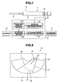
- FIG. 8 An example of the display of a biopsy guide with the utmost position reached by the biopsy needle attached thereto is illustrated using Figure 8 .
- a biopsy guide 15 is displayed on an ultrasound diagnostic image 14 of a screen 13 of the monitor 12 and, in addition, the utmost position 70, constituting the aforesaid boundary of insertion in the piercing direction, that is reached by the biopsy needle is displayed.
- the utmost position 70 reached by the biopsy needle is displayed as an arcuate dotted line or solid line.
- the position of the stop 73 is detected by the aforesaid construction and the utmost position 70 reached by the biopsy needle is updated by the movement interlocked with the movement of the stop 73.
- the utmost position reached by the biopsy needle 4 can be displayed being interlocked with the stop 73 which constitutes the stop mechanism of the mechanical biopsy needle 4, so ease of the piercing operation can be improved, and the operator can perform a biopsy using the biopsy needle with confidence.
- biopsy guides used in the first and second embodiments are not restricted to those illustrated in Figure 5, Figure 6 and Figure 8 and the solid lines could be replaced by the dotted lines or the broken lines.
- the third embodiment addresses these problems.
- an angle output section (not shown) that outputs an angle set by an angle adjuster 27 shown in Figure 2 is built in an ultrasound endoscope 9.
- the angle output section is integral with or constructed separately from the angle adjuster 27 of the tip 24 of the endoscope 2 shown in Figure 2 and is arranged to output an angle set as a resistance value change etc produced by a variable resistor, or as a pulse output produced by an encoder.
- An ultrasound diagnostic signal processing device 100 comprises an angle detection section 101, a biopsy guide display generating section 102, an ultrasound image generating section 103 and a synthesis processing section 104.
- the data output from the angle output section is sent to the angle detection section 101 of the ultrasound diagnostic signal processing device 100.
- the angle detection section 101 calculates the angle of the angle adjuster 27 using the data sent from the angle output section.
- the angle of the angle adjuster 27 calculated by the angle detection section 101 is sent to the biopsy guide display generating section 102.
- the biopsy guide display generating section 102 generates a biopsy guide, to be described.
- the ultrasound echo of the ultrasound endoscope 9 is sent to the ultrasound image generating section 103 of the ultrasound diagnostic signal processing device 100.
- the ultrasound image generating section 103 generates an ultrasound diagnostic image using the ultrasound echo that is sent to it.
- the synthesis processing section 104 synthesizes a biopsy guide generated by the biopsy guide display generating section 102 with the ultrasound diagnostic image generated by the ultrasound image generating section 103 and outputs the result to the monitor 12.
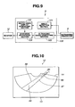
- Figure 10 shows an example of an image output to the monitor 12 by the ultrasound diagnostic signal processing device 100.
- the ultrasound diagnostic signal processing device 100 detects the angle of the angle adjuster 27 of the ultrasound endoscope 9, a biopsy guide 85 displayed on the monitor 12 is displayed in a direction coinciding with the direction of insertion of a biopsy needle image 80.
- the direction of the biopsy guide 85 changes for example as shown in Figure 11 .
- the separation of the biopsy guidelines 86 and 87 is determined taking into account the accuracy of the angle output section incorporated in the ultrasound endoscope 9 and the calculation error of the angle detection section 101.
- display is effected with a width of the order of a few times to ten times that of the biopsy needle image 80.
- dot marks 89 may be displayed with a prescribed separation.
- the operator of the ultrasound endoscope when employing a biopsy needle whose direction of insertion can be varied, can reliably ascertain the direction of insertion of the biopsy needle by means of the biopsy guide 85 displayed on the monitor 12 and can therefore conduct biopsy with confidence.
- an ultrasound diagnostic device 111 is made capable of displaying a biopsy guide coincident with the direction of insertion of the biopsy needle when combined with an ultrasound endoscope 2 that does not have an angle output section that outputs the angle of the angle adjuster.
- An ultrasound diagnostic signal processing device 120 comprises a biopsy needle angle detection section 121, a biopsy guide display generating section 122, an ultrasound image generating section 123 and synthesis processing section 124.
- the ultrasound diagnostic signal processing device 120 generates an ultrasound diagnostic image with the ultrasound image generating section 123 using the ultrasound echoes from the ultrasound endoscope 2.
- the biopsy needle angle detection section 121 performs a calculation of the direction of the biopsy needle as follows, using the ultrasound diagnostic image generated by the ultrasound image generating section 123.
- the biopsy needle is displayed as a linear high-brightness echo as the biopsy needle image 10 of Figure 5 .
- the biopsy needle angle detection section 121 performs detection by performing image processing to ascertain whether or not a high-brightness echo which is linear and not shorter than a prescribed length is present.
- the length of the linear echo that is used by the biopsy needle angle detection section 121 as a standard for deciding whether or not a biopsy needle image is present is specified beforehand as about 1 cm, but the length of the linear echo constituting the standard for this decision can be set at the operator's discretion by using a switch, not shown, on the ultrasound diagnostic signal processing device 120.
- the biopsy needle angle detection section 121 does not detect a linear echo of at least the standard length, it decides that no biopsy needle is being displayed.
- the biopsy guide display generating section 122 therefore displays on the monitor 12 a biopsy guide 15 having the biopsy guidelines 16 and 17 at both ends as adjustment boundary positions of the angle of the biopsy needle as in Figure 5 or Figure 6 . If the biopsy needle angle detection section 121 detect that a linear echo is not shorter than the standard length, it decides that the biopsy needle is present in the ultrasound diagnostic image and sends the result of calculation of its angle information to the biopsy guide display generating section 122.
- the operator can ascertain by means of the biopsy guide displayed on the monitor 12 in what direction the biopsy needle is effecting piercing and so can conduct biopsy with confidence.
- the piercing ultrasound probe disclosed in Japanese Laid-open Patent Application No. H8-229042 or the position detection device of a piercing needle and ultrasound diagnostic device disclosed in Japanese Laid-open Patent Application No. H9-271472 relate to inventions in which the tip position of the biopsy needle is detected and displayed. With these devices, the tip position of the biopsy needle can be specified, but the operator must take care to avoid contacting with blood vessels and so could not perform biopsy with confidence.
- the fifth embodiment addresses this problem.
- an acoustic diagnostic device 131 has a function of stopping the biopsy needle 4.
- An acoustic diagnostic signal processing device 140 comprises an acoustic image generating section 141, blood flow position detection section 142, memory 143, comparison section 144, needle position detection section 145 and needle stop signal generating section 146.
- a biopsy needle insertion/retraction section 150 comprises a biopsy needle insertion/retraction or section casing 151, piston 152 and needle stop mechanism 153.
- the acoustic diagnostic signal processing device 140 outputs a needle stop signal from the needle stop signal generating section 146 by the method to be described.
- a needle stop mechanism 153 of the biopsy insertion/retraction section 150 receives a needle stop signal from the needle stop signal generating section 146. When it receives the needle stop signal, the needle stop mechanism 153 locks the piston 152 with respect to the biopsy needle insertion/retraction section casing 151 so that it cannot move further in the pushing-in direction. By locking the piston 152 by the needle stop mechanism 153, the biopsy needle insertion/retraction section 150 prevents further protrusion of the biopsy needle 4.
- the ultrasound diagnostic signal processing device 140 has a Doppler function like that of an ordinary ultrasound diagnostic device and this Doppler function is turned on when the needle stop signal is generated.
- the ultrasound image generating section 141 displays a Doppler cursor 160 as shown in Figure 14 on the monitor 12, using the signal from the ultrasound endoscope 2, and when blood flow is detected a blood flow information 161 is displayed.
- the blood flow position detection section 142 of the ultrasound diagnostic signal processing device 140 stores the position data at which a Doppler signal is detected by the ultrasound image generating section 141 in the memory 143 and updates the position data stored in the memory 143 every time the position at which the Doppler signal was detected changes.
- the needle position detection section 145 detects the lineal high-brightness echo that is characteristic of a biopsy needle image 10 in which the biopsy needle 4 is drawn on the ultrasound diagnostic image 14 from the ultrasound diagnostic image of the ultrasound image generating section 141 by image processing and calculates the position corresponding to the tip of the biopsy needle 4.
- the comparison section 144 performs a comparison of the position data of a blood clot stored in the memory 143 with the position data of the tip of the biopsy needle 4 calculated by the needle position detection section 145.
- an approach-avoidance distance constituting a criterion for the evaluation of the degree of proximity of the tip position of the biopsy needle 4 and the blood flow position is laid down; it outputs a needle stop signal to the needle stop signal generating section 146 if the tip position of the biopsy needle 4 and the blood flow position are within the approach-avoidance distance.
- the needle stop mechanism 153 thereby locks and stops the biopsy needle 4.
- the approach-avoidance distance is set beforehand at about 1 cm; it can be altered at the operator's discretion using a switch, not shown, on the ultrasound diagnostic device.
- the biopsy guide 15 is simultaneously displayed in Figure 14 , the biopsy guide 15 is not necessarily essential and it would be possible for the ultrasound diagnostic signal processing device 140 not to have a biopsy guide display function.
- the blood flow information 161 is displayed and if the position of the tip of the biopsy needle 4 and the blood flow position are within the approach-avoidance distance, the biopsy needle 4 is stopped, so biopsy can be conducted with confidence.
- an ultrasound diagnostic device 171 illustrates an ultrasound diagnostic device having a function of stopping the biopsy needle 4 of a different construction from that of Figure 13 .
- An ultrasound diagnostic signal processing device 180 comprises an ultrasound image generating section 181, a blood flow position detection section 182, a memory 183, a comparison section 184, a needle position detection section 185, a needle stop signal generating section 186, an angle detection section 187 and a needle protrusion amount detection section 188.
- a biopsy needle insertion/retraction section 190 comprises a biopsy needle insertion/retraction section casing 191, piston 192, needle stop mechanism 193 and protrusion amount output section 194.
- the function of the needle stop mechanism 193 is the same as that of the needle stop mechanism 153 in the biopsy needle insertion/retraction section 150 of Figure 13 .
- the protrusion amount output section 194 outputs data corresponding to the insertion/retraction position of the piston 192 with respect to the biopsy needle insertion/retraction section casing 191 obtained by means of a pulse output produced by an encoder, a variable resistance value produced by a variable resistor, magnetic intensity produced by a magnetic sensor or the like.
- the angle detection mechanism produced by the combination of the ultrasound endoscope 9 and the angle detection section 187 is the same as the construction of the ultrasound diagnostic signal processing device 100 shown in Figure 9 .
- the needle protrusion amount detection section 188 calculates in real time the amount of protrusion of the biopsy needle 4 from the position data of the piston 192 obtained from the protrusion amount output section 194.
- the needle position detection section 185 calculates the tip position of the biopsy needle 4 from the amount of protrusion of the biopsy needle 4 calculated by the needle protrusion amount detection section 188 and the angle of the angle adjuster obtained by the angle adjustment section 187.
- the detection of the blood flow position by the blood flow position detection section 182, storing of the blood flow position data in the memory 183 and the construction, whereby the tip position of the biopsy needle 4 and the blood flow position are compared by the comparison section 184 and a needle stop signal is sent to the needle stop mechanism 193 of the biopsy needle insertion/retraction section 190 from the needle stop signal generating section 186, are the same as in the case of the construction described referring to the ultrasound diagnostic signal processing device 140 of Figure 13 .
- the biopsy needle 4 is stopped when the position of the tip of the biopsy needle 4 and the blood flow position approach are within the approach/excursion distance, so biopsy can be conducted with confidence.
- the ultrasound probe of the embodiments shown in Figure 1 to Figure 15 is not restricted to an ultrasound endoscope but could be combined with an ultrasound probe of the external type.
Description
- The present invention relates to an ultrasound diagnostic device capable of obtaining an ultrasound diagnostic image by performing transmission/reception of ultrasound signals with respect to a subject in a body cavity and piercing the subject with a biopsy needle.
- Conventionally, in the field of medical treatment, use is made of ultrasound diagnostic devices for observation of tissues or blood flow within the body. A typical ultrasound diagnostic device chiefly comprises an ultrasound probe that transmits and receives ultrasound in respect of a part to be examined within the body and the main ultrasound device unit that is connected with the probe. Also, in such an ultrasound diagnostic device, when extracting body fluids or cells of a subject constituted by a part to be observed, a biopsy needle is employed to pierce the subject. Typically the biopsy needle is mounted on an adaptor which is freely detachably mounted on the probe. Some of such devices comprising a biopsy needle display a biopsy guide indicating the direction of insertion of the biopsy needle with respect to the desired part to be observed on a monitor screen when performing piercing whilst conducting observation of for example a B mode image.
- Such prior art ultrasound diagnostic devices that display a biopsy guide are disclosed in
Japanese Laid-open Patent Application No. H3-173542 Japanese Laid-open Patent Application No. H5-176922 - In the ultrasound diagnostic device described in
Japanese Laid-open Patent Application No. H3-173542 - Also, in the ultrasound diagnostic device described in
Japanese Laid-open Patent Application No. H5-176922 - Consequently, in the case of both
Japanese Laid-open Patent Application No. H3-173542 Japanese Laid-open Patent Application No. H5-176922 - In other words, the inventions of the ultrasound diagnostic devices described in
Japanese Laid-open Patent Application No. H3-173542 Japanese Laid-open Patent Application No. H5-176922 - Further techniques which are applicable to ultrasound systems for displaying by drawings or symbols the position of a biopsy needle or the direction of insertion of a biopsy needle in an ultrasound diagnostic image are disclosed in
Japanese Laid-open Patent Application No. H8-299344 Japanese Laid-open Patent Application No. H8-229042 H9-271472 -
Japanese Laid-open Patent Application No. H8-299344 -
Japanese Laid-open Patent Application No. H8-229042 Japanese Laid-open Patent Application No. H9-271472 - However, with such conventional devices whereby an ultrasound diagnostic image could be obtained and a biopsy needle employed, the utmost position reached by the biopsy needle could not be displayed, so the operator could not perform biopsy using the biopsy needle with confidence.
-
United States Patent No. 6,216,029 also discloses a method and system for guiding a needle being inserted into a patient using external ultrasound imaging. This method displays a trajectory for the needle. -
United States Patent No. 6,019,724 discloses a surgical device incorporating an endoscope having an ultrasound probe at a distal tip that generates a narrow ultrasound scan plane designed to identify the position of a surgical tool when it crosses or intersects the scan plane. -
United States Patent No. 4,763,662 discloses an ultrasonic .diagnostic apparatus comprising an endoscope having an ultrasonic probe at a distal end of the endoscope with which the insertion of a puncture needle into a diseased part can be observed. -
Japanese Patent Application Publication No. 09-103433 -
United States Patent No. 4,671,292 describes an ultrasound imaging probe suitable for concentric on-axis biopsy procedures. In particular, it concerns an external ultrasound probe having a central axial aperture through which a biopsy needle is inserted for movement in one dimension, namely along the central axis defined by the aperture. - An object of the present invention is to provide an ultrasound diagnostic device whereby ease and confidence in performing a piercing operation, e.g. during a biopsy, can be improved by displaying the boundary of the piercing direction of the biopsy needle.
- The present invention provides an ultrasound diagnostic device having the features recited in
claim 1. Preferred features of the invention are recited in the dependent claims. - An ultrasound diagnostic device for examining a subject within a body cavity according to the present invention comprises an ultrasound endoscope having an ultrasound image capture section capable of acquiring an ultrasound image of a subject and an insertion/retraction section mounted on an operating section of the endoscope, an insertion/retraction member provided through a section of the endoscope for insertion into the body cavity and having a desired positional relationship with the image capture section and capable of being freely inserted/retracted with respect to the subject by means of the invention/retraction section an insertion/retraction direction alteration section for adjusting the direction of insertion/retraction of the insertion/retraction member, and an image generating section that generates an image comprising an image of the subject acquired by the image capture section and an image of the insertion/retraction member. The ultrasound diagnostic device is characterized by a boundary position superimposition section that superimposes an insertion/retraction boundary marker indicating the position of an insertion/retraction boundary of the insertion/retraction member in the image generated by the image generating section wherein the insertion/retraction boundary marker comprises at least an insertion/retraction direction boundary marker indicating the boundary of the direction of insertion or retraction of the insertion/retraction member adjusted by the insertion/retraction direction alteration section.
- Other features and advantages of the present invention will become fully apparent from the following description.
-
-
Figure 1 to Figure 6 relate to a first embodiment of the present invention. -
Figure 1 is a diagram illustrating the overall construction of an ultrasound diagnostic device; -
Figure 2 is a sectional view of the tip of an ultrasound endoscope; -
Figure 3 is a diagram illustrating the limits of adjustment of a tip angel adjuster of the ultrasound endoscope; -
Figure 4 is a side view illustrating an example of the construction of a biopsy needle and biopsy needle insertion/retraction section; -
Figure 5 is a diagram illustrating an example of a first display of an image output to a monitor by the ultrasound diagnostic device; and -
Figure 6 is a diagram illustrating a second example of a display of an image output to a monitor by the ultrasound diagnostic device. -
Figure 7 and Figure 8 relate to a second embodiment of the present invention. -
Figure 7 is a block diagram illustrating the overall construction of an ultrasound diagnostic device; and -
Figure 8 is a diagram illustrating an example of a display of an image output to a monitor by the ultrasound diagnostic device. -
Figure 9 to Figure 11 relate to a third embodiment of the present invention. -
Figure 9 is a block diagram illustrating the overall construction of an ultrasound diagnostic device; -
Figure 10 is a diagram illustrating an example of a first display of an image output to a monitor by an ultrasound diagnostic device; -
Figure 11 is a diagram illustrating a second example of a display of an image output to a monitor by an ultrasound diagnostic device; and -
Figure 12 is a block diagram illustrating the overall construction of an ultrasound diagnostic device according to a fourth embodiment of the present invention. -
Figure 13 and 14 relate to a fifth embodiment of the present invention. -
Figure 13 is a block diagram illustrating the overall layout of an ultrasound diagnostic device; and -
Figure 14 is a diagram illustrating an example of a display of an image output to a monitor by an ultrasound diagnostic device; and -
Figure 15 is a block diagram illustrating the overall construction of an ultrasound diagnostic device according to a sixth embodiment of the present invention. - Embodiments of the present invention are described below with reference to the drawings.
- First of all, the overall construction of an ultrasound diagnostic device will be described using
Figure 1 . - As shown in
Figure 1 , an ultrasounddiagnostic device 1 comprises anultrasound endoscope 2, an ultrasound diagnosticsignal processing device 11 and amonitor 12 and is arranged so as to be able to obtain an ultrasound diagnostic image by performing transmission/reception of ultrasound signals with respect to an intracavitary subject. - The
ultrasound endoscope 2 comprises aninsertion section 21 inserted into the body cavity, anoperating section 22 and a connectingcord 23. - The
ultrasound endoscope 2 comprises anultrasound probe 25 and a biopsyneedle protrusion port 26 at atip 24 of theinsertion section 21. - The
ultrasound endoscope 2 is connected with the ultrasound diagnosticsignal processing device 11 and performs transmission/reception of ultrasound signals with respect to the body by means of theultrasound probe 25. - The ultrasound diagnostic
signal processing device 11 controls theultrasound probe 25 of theultrasound endoscope 2 and processes the signals obtained from theultrasound probe 25, and generates an ultrasound diagnostic image by known techniques and displays this on themonitor 12. - A biopsy needle insertion/
retraction section 3 is mounted on theoperating section 22 of theultrasound endoscope 2. A biopsy needle insertion/retraction section 3 is employed to insert/retract abiopsy needle 4, which is a medical instrument, forward and backward. Thebiopsy needle 4 is inserted from the biopsy needle insertion/retraction section 3 through theinsertion section 21 of theultrasound endoscope 2 so that the tip of the needle protrudes from the biopsyneedle protrusion port 26 of thetip 24 of theinsertion section 21 and so can pierce the aforesaid subject. - The
monitor 12 displays an image corresponding to the ultrasound diagnostic image that is output from the ultrasound diagnosticsignal processing device 11. The ultrasound diagnosticsignal processing device 11 has a function whereby to superimpose the insertion boundaries of the piercing direction of thebiopsy needle 4 on the display of themonitor 12. - Next, the
tip 24 of theultrasound endoscope 2 will be described in detail usingFigure 2 . - The
ultrasound probe 25 and biopsyneedle protrusion port 26 are provided at thetip 24 of theultrasound endoscope 2. - An
angle adjuster 27 for adjusting the angle with which thebiopsy needle 4 protrudes from the tip of theultrasound endoscope 2 is provided in the interior of the biopsyneedle protrusion port 26. In this case, theangle adjuster 27 is mounted in a condition in which it is rotatable by arotary shaft 28 in a direction perpendicular to the longitudinal direction of theinsertion section 21. Furthermore, theangle adjuster 27 is made capable of rotating between one and the other adjustment boundary positions by operation of theoperating section 22 shown inFigure 1 . -
Figure 2 shows with a solid line the case where thebiopsy needle 4 in the one adjustment boundary position of theangle adjuster 27 protrudes from thetip 24 of theultrasound endoscope 2. The broken line shows the position when thebiopsy needle 4 is in the other adjustment boundary position. - In the one adjustment boundary position, the
angle adjuster 27 andbiopsy needle 4 are in the condition of smallest angle with respect to the longitudinal direction of theinsertion section 21. The angle with which thebiopsy needle 4 protrudes from thetip 24 of theultrasound endoscope 2 depends on the type ofultrasound endoscope 2 and so the angle is a known quantity. - In
Figure 3 , the case where thebiopsy needle 4 protrudes from thetip 24 of theultrasound endoscope 2 in the aforesaid other adjustment boundary position of theangle adjuster 27 is indicated by a solid line. The broken line indicates the position of thebiopsy needle 4 at the one adjustment boundary position. In case that theangle adjuster 27 and thebiopsy needle 4 are positioned in the other adjustment boundary position, the angle with respect to the longitudinal direction of theinsertion section 21 is largest. In this case also, the angle with which thebiopsy needle 4 protrudes from thetip 24 of theultrasound endoscope 2 is a known quantity. - With this construction, the
angle adjuster 27 is provided within theaforesaid insertion section 21 and has a function whereby to alter the direction of piercing of theaforesaid biopsy needle 4 by movement thereof. - The ultrasound wave diagnostic
signal processing device 11 superimposes the movement range of thisangle adjuster 27 on the ultrasound diagnostic image of themonitor 12. -
Figure 4 illustrates an example of the construction of the biopsy needle insertion/retraction section 3 and thebiopsy needle 4. - The biopsy needle insertion/
retraction section 3 comprises a biopsy needle insertion/retraction section casing 31 and apiston 32. Thebiopsy needle 4 is mounted on thepiston 32 and is inserted/retracted with forward/backward movement of thepiston 32. - In the condition shown in
Figure 1 in which the biopsy needle insertion/retraction section 3 is mounted on theultrasound endoscope 2, thebiopsy needle 4 protrudes from thetip 24 of theultrasound endoscope 2 when the operator pushes thepiston 32. - Although an example of the simplest construction of the biopsy needle insertion/
retraction section 3 is illustrated inFigure 4 , the biopsy needle insertion/retraction section 3 is not restricted to a biopsy needle insertion/retraction section of the construction shown inFigure 4 . It would be possible to employ a biopsy needle insertion/retraction section provided with a stop for preventing pushing the end of the piston beyond a pre-set stroke, or a biopsy needle insertion/attraction section wherein the piston is advanced by a pre-set stroke by operation of a button. -
Figure 5 shows an example of the display of an image which is output to themonitor 12 by the ultrasound diagnosticsignal processing device 11. - In
Figure 5 , a sector-shaped ultrasounddiagnostic image 14 is displayed on thescreen 13 of themonitor 12. Thebiopsy needle image 10 is an ultrasound image corresponding to thebiopsy needle 4 displayed on the ultrasounddiagnostic image 14 and is displayed as a high-brightness echo of linear shape. Display or non-display of thebiopsy guide 15 can be selected as desired; this display is superimposed on the ultrasounddiagnostic image 14 when display is selected by a changeover switch (not shown) of the ultrasound diagnosticsignal processing device 11. Thebiopsy guide 15 comprisesbiopsy guidelines angle adjuster 27 of theultrasound endoscope 2 is in the one adjustment boundary position shown inFigure 2 , thebiopsy guideline 16 coincides with the direction of thebiopsy needle image 10 displayed on the ultrasounddiagnostic image 14. As described above, if the type of theultrasound endoscope 2 is determined, the angle with which thebiopsy needle 4 protrudes when thisangle adjuster 27 is in the one adjustment boundary position is a known quantity, so thebiopsy guideline 16 may be displayed in a direction coinciding with this direction. In the ultrasound diagnosticsignal processing device 11, means for specifying the type of theultrasound endoscope 2 connected thereto can easily be implemented using known techniques. Thebiopsy guideline 17 likewise coincides with the direction in which thebiopsy needle image 10 is displayed on the ultrasounddiagnostic image 14 when theangle adjuster 27 of theultrasound endoscope 2 shown inFigure 3 is in the other adjustment boundary position. Thebiopsy needle 10 must therefore be displayed within the area defined by thebiopsy guidelines - Also, since the
piston 32 of biopsy needle insertion/retraction section 3 shown inFigure 4 is chiefly operated manually by the operator,graduations 18 providing a scale of the length with which how deep thepiston 32 should be pushed in are displayed on thebiopsy guidelines - Also, instead of the display of
graduations 18 or in combination therewith, dot marks 19 may be displayed at prescribed intervals within the range defined bybiopsy guidelines Fig. 6 . By displaying the dot marks 19, the length of thebiopsy needle image 10 can easily be recognized by the operator even when thebiopsy needle image 10 is remote from thebiopsy guidelines - Thus, with the first embodiment, biopsy can be performed confidently, since the operator can recognize the range through which the biopsy needle has advanced by using the display of the
biopsy guide 15, even in cases where the direction of the biopsy needle cannot be directly visually ascertained by the operator, such as in the case of an ultrasound endoscope. - Furthermore, with the first embodiment, by displaying the dot marks 19 as shown in
Figure 6 orgraduations 18 as shown inFigure 5 , the length of advance can be ascertained, wherever the diagnostic needle has advanced to within the biopsy guide range. - In the description of
Figure 7 and Figure 8 , structural elements which are the same as in the first embodiment shown inFigure 1 to Figure 6 are given the same reference symbols and further description thereof is omitted. - In
Figure 7 , an ultrasounddiagnostic device 5 comprises theultrasound endoscope 2, ultrasound diagnosticsignal processing device 6, biopsy needle insertion/retraction section 7 and monitor 12. - An example is illustrated in which the ultrasound diagnostic
signal processing device 6 can be combined with a biopsy insertion/retraction section 7 having a mechanism for detecting the maximum amount of protrusion of thebiopsy needle 4. - The biopsy diagnostic
signal processing device 6 comprises a maximum protrusionamount detection section 61, a biopsy guidedisplay generating section 62, an ultrasoundimage generating section 63 and asynthesis processing section 64. - The biopsy needle insertion/
retraction section 7 comprises a biopsy needle insertion/retraction section casing 71, apiston 72 and astop 73. Thebiopsy needle 4 is mounted on thepiston 72. - The
stop 73 is mounted at the proximal end of the biopsy needle insertion/retraction casing 71 in a condition in which its position can be adjusted. Thestop 73 serves to prevent thepiston 72 being pushed in by more than stroke set by position adjustment in advance. - A
sensor 74 is incorporated in thestop 73. Thesensor 74 outputs data corresponding to the fixed position of thestop 73 to the ultrasound diagnosticsignal processing device 6. - The
sensor 74 is constituted by for example a sensor comprising an encoder that converts the amount of movement in the forward/backward direction of thestop 73 into the number of pulses to output, or a sensor wherein the resistance value of a variable resistance changes with forward/backward movement of thestop 73 and is converted into the amount of movement by detecting the voltage difference across the two ends of this variable resistance, or a magnetic sensor wherein the distance from the end of thepiston 72 is measured by detecting the strength of magnetism formed by a magnet embedded in one end of thepiston 72. - The data that is output by the
sensor 74 is input to the maximum protrusionamount detection section 61 within the ultrasound diagnosticsignal processing device 6. The maximum protrusionamount detection section 61 detects the set position i.e. the maximum protrusion amount of thestop 73 using the data from thesensor 74. - The data of the detection result of the maximum protrusion
amount detection section 61 is sent to the biopsy guidedisplay generating section 62. Based on the data from the maximum protrusionamount detection section 61, the biopsy guidedisplay generating section 62 generates an image of the biopsy guide with the utmost position reached by the biopsy needle, to be described below, attached thereto. - The ultrasound
image generating section 63 processes the signal obtained from theultrasound endoscope 2, generates an ultrasound diagnostic image by known techniques and outputs this to thesynthesis processing section 64. - The image of the biopsy guide with the utmost position reached by the biopsy needle attached thereto created by the biopsy guide
display generating section 62 is synthesized with the ultrasound diagnostic image generated by the ultrasoundimage generating section 63 in thesynthesis processing section 64 and displayed on themonitor 12. - An example of the display of a biopsy guide with the utmost position reached by the biopsy needle attached thereto is illustrated using
Figure 8 . - As shown in
Figure 8 , abiopsy guide 15 is displayed on an ultrasounddiagnostic image 14 of ascreen 13 of themonitor 12 and, in addition, theutmost position 70, constituting the aforesaid boundary of insertion in the piercing direction, that is reached by the biopsy needle is displayed. Theutmost position 70 reached by the biopsy needle is displayed as an arcuate dotted line or solid line. - When the operator alters the position of the
stop 73 of the biopsy needle insertion/retraction section 7, the position of thestop 73 is detected by the aforesaid construction and theutmost position 70 reached by the biopsy needle is updated by the movement interlocked with the movement of thestop 73. - With the second embodiment, the same benefits as in the case of the first embodiment illustrated in
Figure 1 to Figure 6 are obtained and, even in the case of abiopsy needle 4 wherein the stop position of thebiopsy needle 4 - can be altered, the utmost position reached by the
biopsy needle 4 can be displayed being interlocked with thestop 73 which constitutes the stop mechanism of themechanical biopsy needle 4, so ease of the piercing operation can be improved, and the operator can perform a biopsy using the biopsy needle with confidence. - It should be noted that the biopsy guides used in the first and second embodiments are not restricted to those illustrated in
Figure 5, Figure 6 andFigure 8 and the solid lines could be replaced by the dotted lines or the broken lines. - However, when, as in the case of an ultrasound endoscope, the direction of protrusion of the biopsy needle after insertion into the body cavity can be varied, the operator cannot specify the direction of insertion of the biopsy needle by direct visual observation. There was previously no biopsy guide display in existence that displayed the direction of protrusion with respect to a biopsy needle whose direction of insertion could not be specified by the operator, as is the case in regard to an ultrasound endoscope. The operator of the ultrasound endoscope therefore previously had no means at all of knowing the direction of insertion of the biopsy needle and so could not conduct a biopsy with confidence.
- The third embodiment addresses these problems.
- In the description of
Figure 9 to Figure 11 , structural elements which are the same as in the case of the first embodiment illustrated inFigure 1 to Figure 6 are given the same reference symbols and further description thereof is omitted. Also, portions which are not shown inFigure 9 will be described with reference toFigure 2 instead. - In
Figure 9 , an angle output section (not shown) that outputs an angle set by anangle adjuster 27 shown inFigure 2 is built in anultrasound endoscope 9. The angle output section is integral with or constructed separately from theangle adjuster 27 of thetip 24 of theendoscope 2 shown inFigure 2 and is arranged to output an angle set as a resistance value change etc produced by a variable resistor, or as a pulse output produced by an encoder. - An ultrasound diagnostic
signal processing device 100 comprises anangle detection section 101, a biopsy guidedisplay generating section 102, an ultrasoundimage generating section 103 and asynthesis processing section 104. - The data output from the angle output section is sent to the
angle detection section 101 of the ultrasound diagnosticsignal processing device 100. Theangle detection section 101 calculates the angle of theangle adjuster 27 using the data sent from the angle output section. The angle of theangle adjuster 27 calculated by theangle detection section 101 is sent to the biopsy guidedisplay generating section 102. The biopsy guidedisplay generating section 102 generates a biopsy guide, to be described. - In addition, the ultrasound echo of the
ultrasound endoscope 9 is sent to the ultrasoundimage generating section 103 of the ultrasound diagnosticsignal processing device 100. The ultrasoundimage generating section 103 generates an ultrasound diagnostic image using the ultrasound echo that is sent to it. Thesynthesis processing section 104 synthesizes a biopsy guide generated by the biopsy guidedisplay generating section 102 with the ultrasound diagnostic image generated by the ultrasoundimage generating section 103 and outputs the result to themonitor 12. -
Figure 10 shows an example of an image output to themonitor 12 by the ultrasound diagnosticsignal processing device 100. - Since, as described previously, the ultrasound diagnostic
signal processing device 100 detects the angle of theangle adjuster 27 of theultrasound endoscope 9, abiopsy guide 85 displayed on themonitor 12 is displayed in a direction coinciding with the direction of insertion of abiopsy needle image 80. - When the operator changes the angle of the
angle adjuster 27, the direction of the biopsy guide 85 changes for example as shown inFigure 11 . The separation of thebiopsy guidelines ultrasound endoscope 9 and the calculation error of theangle detection section 101. Typically, display is effected with a width of the order of a few times to ten times that of thebiopsy needle image 80. Also, if required, dot marks 89 may be displayed with a prescribed separation. - As described above, with the third embodiment, since it is possible to display a biopsy guide of the direction coincident with the direction of insertion of the biopsy needle, the operator of the ultrasound endoscope, when employing a biopsy needle whose direction of insertion can be varied, can reliably ascertain the direction of insertion of the biopsy needle by means of the
biopsy guide 85 displayed on themonitor 12 and can therefore conduct biopsy with confidence. - In the description of
Figure 12 , structural elements which are the same as in the case of the first embodiment shown inFigure 1 to Figure 6 are given the same reference symbols and further description thereof is omitted. - In
Figure 12 , an ultrasounddiagnostic device 111 is made capable of displaying a biopsy guide coincident with the direction of insertion of the biopsy needle when combined with anultrasound endoscope 2 that does not have an angle output section that outputs the angle of the angle adjuster. - An ultrasound diagnostic
signal processing device 120 comprises a biopsy needleangle detection section 121, a biopsy guidedisplay generating section 122, an ultrasoundimage generating section 123 andsynthesis processing section 124. - The ultrasound diagnostic
signal processing device 120 generates an ultrasound diagnostic image with the ultrasoundimage generating section 123 using the ultrasound echoes from theultrasound endoscope 2. The biopsy needleangle detection section 121 performs a calculation of the direction of the biopsy needle as follows, using the ultrasound diagnostic image generated by the ultrasoundimage generating section 123. - If the biopsy needle is present on the ultrasound diagnostic image, the biopsy needle is displayed as a linear high-brightness echo as the
biopsy needle image 10 ofFigure 5 . The biopsy needleangle detection section 121 performs detection by performing image processing to ascertain whether or not a high-brightness echo which is linear and not shorter than a prescribed length is present. - The length of the linear echo that is used by the biopsy needle
angle detection section 121 as a standard for deciding whether or not a biopsy needle image is present is specified beforehand as about 1 cm, but the length of the linear echo constituting the standard for this decision can be set at the operator's discretion by using a switch, not shown, on the ultrasound diagnosticsignal processing device 120. - If the biopsy needle
angle detection section 121 does not detect a linear echo of at least the standard length, it decides that no biopsy needle is being displayed. The biopsy guidedisplay generating section 122 therefore displays on the monitor 12 abiopsy guide 15 having thebiopsy guidelines Figure 5 or Figure 6 . If the biopsy needleangle detection section 121 detect that a linear echo is not shorter than the standard length, it decides that the biopsy needle is present in the ultrasound diagnostic image and sends the result of calculation of its angle information to the biopsy guidedisplay generating section 122. Regarding the method of displaying the biopsy guide on the monitor after the angle calculation information of the biopsy needle has been sent by the biopsy guidedisplay generating section 122, this is the same as in the case of the construction of the biopsy guidedisplay generating section 102 of the ultrasound diagnosticsignal processing device 100 shown inFigure 9 . The biopsy guide displayed on themonitor 12 is therefore the same as in the case ofFigure 10 orFigure 11 . - With the fourth embodiment, even in cases where the ultrasound endoscope does not have an angle output section that outputs the angle of the angle adjuster, the operator can ascertain by means of the biopsy guide displayed on the
monitor 12 in what direction the biopsy needle is effecting piercing and so can conduct biopsy with confidence. - The piercing ultrasound probe disclosed in
Japanese Laid-open Patent Application No. H8-229042 Japanese Laid-open Patent Application No. H9-271472 - The fifth embodiment addresses this problem.
- In the description of
Figure 13 and Figure 14 , structural elements which are same as in the case of the first embodiment shown inFigure 1 to Figure 6 are given the same reference symbols and further description thereof is omitted. - In
Figure 13 , an acousticdiagnostic device 131 has a function of stopping thebiopsy needle 4. - An acoustic diagnostic
signal processing device 140 comprises an acousticimage generating section 141, blood flowposition detection section 142,memory 143,comparison section 144, needleposition detection section 145 and needle stopsignal generating section 146. - A biopsy needle insertion/
retraction section 150 comprises a biopsy needle insertion/retraction orsection casing 151,piston 152 andneedle stop mechanism 153. - The acoustic diagnostic
signal processing device 140 outputs a needle stop signal from the needle stopsignal generating section 146 by the method to be described. Aneedle stop mechanism 153 of the biopsy insertion/retraction section 150 receives a needle stop signal from the needle stopsignal generating section 146. When it receives the needle stop signal, theneedle stop mechanism 153 locks thepiston 152 with respect to the biopsy needle insertion/retraction section casing 151 so that it cannot move further in the pushing-in direction. By locking thepiston 152 by theneedle stop mechanism 153, the biopsy needle insertion/retraction section 150 prevents further protrusion of thebiopsy needle 4. - The method of generating the needle stop signal will now be described.
- The ultrasound diagnostic
signal processing device 140 has a Doppler function like that of an ordinary ultrasound diagnostic device and this Doppler function is turned on when the needle stop signal is generated. - When the Doppler function of the ultrasound diagnostic
signal processing device 140 is turned on, the ultrasoundimage generating section 141 displays aDoppler cursor 160 as shown inFigure 14 on themonitor 12, using the signal from theultrasound endoscope 2, and when blood flow is detected ablood flow information 161 is displayed. The blood flowposition detection section 142 of the ultrasound diagnosticsignal processing device 140 stores the position data at which a Doppler signal is detected by the ultrasoundimage generating section 141 in thememory 143 and updates the position data stored in thememory 143 every time the position at which the Doppler signal was detected changes. The needleposition detection section 145 detects the lineal high-brightness echo that is characteristic of abiopsy needle image 10 in which thebiopsy needle 4 is drawn on the ultrasounddiagnostic image 14 from the ultrasound diagnostic image of the ultrasoundimage generating section 141 by image processing and calculates the position corresponding to the tip of thebiopsy needle 4. Thecomparison section 144 performs a comparison of the position data of a blood clot stored in thememory 143 with the position data of the tip of thebiopsy needle 4 calculated by the needleposition detection section 145. - In the
comparison section 144, an approach-avoidance distance constituting a criterion for the evaluation of the degree of proximity of the tip position of thebiopsy needle 4 and the blood flow position is laid down; it outputs a needle stop signal to the needle stopsignal generating section 146 if the tip position of thebiopsy needle 4 and the blood flow position are within the approach-avoidance distance. Theneedle stop mechanism 153 thereby locks and stops thebiopsy needle 4. In this case, the approach-avoidance distance is set beforehand at about 1 cm; it can be altered at the operator's discretion using a switch, not shown, on the ultrasound diagnostic device. - Although the
biopsy guide 15 is simultaneously displayed inFigure 14 , thebiopsy guide 15 is not necessarily essential and it would be possible for the ultrasound diagnosticsignal processing device 140 not to have a biopsy guide display function. - With the fifth embodiment, if blood flow is detected, the
blood flow information 161 is displayed and if the position of the tip of thebiopsy needle 4 and the blood flow position are within the approach-avoidance distance, thebiopsy needle 4 is stopped, so biopsy can be conducted with confidence. - In
Figure 15 , an ultrasounddiagnostic device 171 illustrates an ultrasound diagnostic device having a function of stopping thebiopsy needle 4 of a different construction from that ofFigure 13 . - An ultrasound diagnostic
signal processing device 180 comprises an ultrasoundimage generating section 181, a blood flowposition detection section 182, amemory 183, acomparison section 184, a needleposition detection section 185, a needle stopsignal generating section 186, anangle detection section 187 and a needle protrusionamount detection section 188. - A biopsy needle insertion/
retraction section 190 comprises a biopsy needle insertion/retraction section casing 191,piston 192,needle stop mechanism 193 and protrusionamount output section 194. - The function of the
needle stop mechanism 193 is the same as that of theneedle stop mechanism 153 in the biopsy needle insertion/retraction section 150 ofFigure 13 . The protrusionamount output section 194 outputs data corresponding to the insertion/retraction position of thepiston 192 with respect to the biopsy needle insertion/retraction section casing 191 obtained by means of a pulse output produced by an encoder, a variable resistance value produced by a variable resistor, magnetic intensity produced by a magnetic sensor or the like. - The angle detection mechanism produced by the combination of the
ultrasound endoscope 9 and theangle detection section 187 is the same as the construction of the ultrasound diagnosticsignal processing device 100 shown inFigure 9 . The needle protrusionamount detection section 188 calculates in real time the amount of protrusion of thebiopsy needle 4 from the position data of thepiston 192 obtained from the protrusionamount output section 194. - The needle
position detection section 185 calculates the tip position of thebiopsy needle 4 from the amount of protrusion of thebiopsy needle 4 calculated by the needle protrusionamount detection section 188 and the angle of the angle adjuster obtained by theangle adjustment section 187. The detection of the blood flow position by the blood flowposition detection section 182, storing of the blood flow position data in thememory 183 and the construction, whereby the tip position of thebiopsy needle 4 and the blood flow position are compared by thecomparison section 184 and a needle stop signal is sent to theneedle stop mechanism 193 of the biopsy needle insertion/retraction section 190 from the needle stopsignal generating section 186, are the same as in the case of the construction described referring to the ultrasound diagnosticsignal processing device 140 ofFigure 13 . - With the sixth embodiment, just as in the case of the fifth embodiment shown in
Figure 13 and Figure 14 , thebiopsy needle 4 is stopped when the position of the tip of thebiopsy needle 4 and the blood flow position approach are within the approach/excursion distance, so biopsy can be conducted with confidence. - The ultrasound probe of the embodiments shown in
Figure 1 to Figure 15 is not restricted to an ultrasound endoscope but could be combined with an ultrasound probe of the external type. - Having described the preferred embodiments of the invention referring to the accompanying drawings, it should be understood that the present invention is not limited to those precise embodiments, and various changes and modifications thereof could be made by one skilled in the art without departing from the invention as defined in the appended claims.
Claims (10)
- An ultrasound diagnostic device (1) for examining a subject within a body cavity, comprising:an ultrasound endoscope (2) having an ultrasound image capture section (25) capable of acquiring an image of a subject and an insertion/retraction section (3, 7, 150, 190) mounted on an operating section (22) of the endoscope (2);an insertion/retraction member (4) provided through a section (21) of the endoscope (2) for insertion into the body cavity, the insertion/retraction member (4) having a desired positional relationship with the image capture section (25) and capable of being freely inserted/retracted with respect to the subject by means of the insertion /retraction section (3,7,150,190),an insertion/retraction direction alteration section (27, 28) for adjusting the direction of insertion/retraction of the insertion/retraction member (4), andan image generating section (11, 12) that generates an image (14) comprising an image of the subject acquired by the ultrasound image capture section (25) and an image of the insertion/retraction member (4);characterized in that the device (1) further comprises:a boundary position superimposition section (11) that superimposes an insertion/retraction boundary marker (15) indicating the position of the insertion/retraction boundary of the insertion/retraction member (4) in the image (14) generated by the image generating section (11, 12), wherein the insertion/retraction boundary marker (15) comprises at least an insertion/retraction direction boundary marker (16,17) indicating the boundary of the direction of insertion/retraction of the insertion/retraction member (4) adjusted by the insertion/retraction direction alteration section (27, 28).
- The device (1) for examining a subject according to Claim 1, characterized in that the image capture section (25) acquires an image of the subject by sending ultrasound to the subject and receiving ultrasound therefrom.
- The device (1) for examining a subject according to Claim 1, characterized in that the insertion/retraction boundary marker (15) comprises an insertion/retraction amount marker (18, 19) that indicates the amount of insertion/retraction of the insertion/retraction member (4).
- The device (1) for examining a subject according to Claim 1, characterized in that the boundary position superimposition section (11) detects the insertion/retraction member (4) by performing image processing and calculates a position of the insertion/retraction boundary marker (15).
- The device (1) for examining a subject according to Claim 1, characterized in that the insertion/retraction section (3, 7, 150, 190) includes a stop (73, 153, 193), which is adapted to prevent the insertion/ retraction member (4) from being inserted with respect to the subject beyond a stopping position that is adapted to be pre-set by an operator and/or detected.
- The device (1) for examining a subject according to Claim 5, characterized in that a fixed position of the stop (73) in the insertion/retraction section (7) is adjustable to pre-set said stopping position of the insertion/retraction member (4).
- The device (1) for examining a subject according to Claim 6, characterized in that a sensor (74) is incorporated in the stop (73), wherein the sensor (74) outputs data corresponding to the fixed position of the stop (73).
- The device (1) for examining a subject according to Claim 5, characterized in that the stop (153, 193) is adapted to receive a stop signal from a diagnostic signal processing device (140, 180), which detects an inserted position of a tip of the insertion/retraction member (4).
- The device (1) for examining a subject according to Claim 8, characterized in that the diagnostic signal processing device (140, 180) is adapted to detect the inserted position of the tip of the insertion/retraction member (4) relative to a detected blood-flow, whereby the stop (153, 193) receives the stop signal from the diagnostic signal processing device (140, 180) when the tip of the insertion/retraction member (4) is within a pre-set approach-avoidance distance of the detected blood-flow.
- The device (1) for examining a subject according to Claim 1, characterized by further comprising an angle detection section (101) for detecting an angle of insertion/retraction of the insertion/retraction member (4) adjusted by the insertion/retraction direction alteration section (27, 28), wherein the boundary position superimposition section (11) superimposes the insertion/retradion boundary marker (15) in the image (14) based on the angle detected by the angle detection section (101).
Applications Claiming Priority (2)
| Application Number | Priority Date | Filing Date | Title |
|---|---|---|---|
| JP2001325433A JP2003126093A (en) | 2001-10-23 | 2001-10-23 | Ultrasonic diagnostic apparatus |
| JP2001325433 | 2001-10-23 |
Publications (3)
| Publication Number | Publication Date |
|---|---|
| EP1306054A2 EP1306054A2 (en) | 2003-05-02 |
| EP1306054A3 EP1306054A3 (en) | 2004-01-14 |
| EP1306054B1 true EP1306054B1 (en) | 2008-06-04 |
Family
ID=19141995
Family Applications (1)
| Application Number | Title | Priority Date | Filing Date |
|---|---|---|---|
| EP02023670A Expired - Lifetime EP1306054B1 (en) | 2001-10-23 | 2002-10-22 | A device for examining a subject capable of marking a boundary range for the insertion/retraction of a member |
Country Status (4)
| Country | Link |
|---|---|
| US (1) | US6786870B2 (en) |
| EP (1) | EP1306054B1 (en) |
| JP (1) | JP2003126093A (en) |
| DE (1) | DE60226936D1 (en) |
Families Citing this family (89)
| Publication number | Priority date | Publication date | Assignee | Title |
|---|---|---|---|---|
| US8137279B2 (en) | 2001-10-16 | 2012-03-20 | Envisioneering, Llc | Scanning probe |
| US20050159676A1 (en) * | 2003-08-13 | 2005-07-21 | Taylor James D. | Targeted biopsy delivery system |
| JP4537698B2 (en) * | 2003-12-25 | 2010-09-01 | 株式会社東芝 | Ultrasonic diagnostic equipment |
| JP2005253742A (en) * | 2004-03-12 | 2005-09-22 | Matsushita Electric Ind Co Ltd | Ultrasonic diagnosis system |
| US8795195B2 (en) * | 2004-11-29 | 2014-08-05 | Senorx, Inc. | Graphical user interface for tissue biopsy system |
| US7892177B2 (en) | 2005-02-28 | 2011-02-22 | Scimed Life Systems, Inc. | Systems and methods for estimating the length and position of a stent to be applied within a patient |
| US20070038089A1 (en) * | 2005-06-29 | 2007-02-15 | Olympus Medical Systems Corp. | Transurethral diagnostic method and treatment method using ultrasonic endoscope |
| US8784336B2 (en) | 2005-08-24 | 2014-07-22 | C. R. Bard, Inc. | Stylet apparatuses and methods of manufacture |
| US7835785B2 (en) | 2005-10-04 | 2010-11-16 | Ascension Technology Corporation | DC magnetic-based position and orientation monitoring system for tracking medical instruments |
| JP4789644B2 (en) * | 2006-02-14 | 2011-10-12 | 株式会社日立メディコ | Ultrasonic diagnostic equipment |
| JP4958455B2 (en) * | 2006-03-10 | 2012-06-20 | 株式会社日立メディコ | Ultrasonic diagnostic equipment |
| US9539025B2 (en) * | 2006-03-24 | 2017-01-10 | B-K Medical Aps | Biopsy system |
| US20080097218A1 (en) * | 2006-08-24 | 2008-04-24 | Boston Scientific Scimed, Inc. | Blood vessel puncture locating apparatus and method |
| US8388546B2 (en) | 2006-10-23 | 2013-03-05 | Bard Access Systems, Inc. | Method of locating the tip of a central venous catheter |
| US7794407B2 (en) | 2006-10-23 | 2010-09-14 | Bard Access Systems, Inc. | Method of locating the tip of a central venous catheter |
| JP2008253524A (en) * | 2007-04-04 | 2008-10-23 | Olympus Medical Systems Corp | Ultrasound observation system |
| JP5060204B2 (en) * | 2007-08-13 | 2012-10-31 | 株式会社東芝 | Ultrasonic diagnostic apparatus and program |
| US8088072B2 (en) | 2007-10-12 | 2012-01-03 | Gynesonics, Inc. | Methods and systems for controlled deployment of needles in tissue |
| US10751509B2 (en) | 2007-11-26 | 2020-08-25 | C. R. Bard, Inc. | Iconic representations for guidance of an indwelling medical device |
| US10449330B2 (en) | 2007-11-26 | 2019-10-22 | C. R. Bard, Inc. | Magnetic element-equipped needle assemblies |
| US9649048B2 (en) | 2007-11-26 | 2017-05-16 | C. R. Bard, Inc. | Systems and methods for breaching a sterile field for intravascular placement of a catheter |
| US8849382B2 (en) | 2007-11-26 | 2014-09-30 | C. R. Bard, Inc. | Apparatus and display methods relating to intravascular placement of a catheter |
| US10524691B2 (en) | 2007-11-26 | 2020-01-07 | C. R. Bard, Inc. | Needle assembly including an aligned magnetic element |
| US8781555B2 (en) | 2007-11-26 | 2014-07-15 | C. R. Bard, Inc. | System for placement of a catheter including a signal-generating stylet |
| US9521961B2 (en) | 2007-11-26 | 2016-12-20 | C. R. Bard, Inc. | Systems and methods for guiding a medical instrument |
| ES2832713T3 (en) | 2007-11-26 | 2021-06-11 | Bard Inc C R | Integrated system for intravascular catheter placement |
| US20090247876A1 (en) * | 2008-03-28 | 2009-10-01 | Cannon Jr Charles W | Laparoscopic probe guidance system |
| KR101495768B1 (en) | 2008-04-29 | 2015-02-25 | 삼성전자 주식회사 | Image guided syringe apparatus and method for medical service |
| US9901714B2 (en) | 2008-08-22 | 2018-02-27 | C. R. Bard, Inc. | Catheter assembly including ECG sensor and magnetic assemblies |
| JP5269528B2 (en) * | 2008-09-09 | 2013-08-21 | オリンパスメディカルシステムズ株式会社 | Ultrasonic image display device |
| US8968210B2 (en) | 2008-10-01 | 2015-03-03 | Covidien LLP | Device for needle biopsy with integrated needle protection |
| US9186128B2 (en) | 2008-10-01 | 2015-11-17 | Covidien Lp | Needle biopsy device |
| US11298113B2 (en) | 2008-10-01 | 2022-04-12 | Covidien Lp | Device for needle biopsy with integrated needle protection |
| US9332973B2 (en) | 2008-10-01 | 2016-05-10 | Covidien Lp | Needle biopsy device with exchangeable needle and integrated needle protection |
| US9782565B2 (en) | 2008-10-01 | 2017-10-10 | Covidien Lp | Endoscopic ultrasound-guided biliary access system |
| US8437833B2 (en) | 2008-10-07 | 2013-05-07 | Bard Access Systems, Inc. | Percutaneous magnetic gastrostomy |
| US9532724B2 (en) | 2009-06-12 | 2017-01-03 | Bard Access Systems, Inc. | Apparatus and method for catheter navigation using endovascular energy mapping |
| CN102802514B (en) | 2009-06-12 | 2015-12-02 | 巴德阿克塞斯系统股份有限公司 | Catheter tip positioning equipment |
| US9445734B2 (en) | 2009-06-12 | 2016-09-20 | Bard Access Systems, Inc. | Devices and methods for endovascular electrography |
| AU2010300677B2 (en) | 2009-09-29 | 2014-09-04 | C.R. Bard, Inc. | Stylets for use with apparatus for intravascular placement of a catheter |
| US8761862B2 (en) * | 2009-10-09 | 2014-06-24 | Stephen F. Ridley | Ultrasound guided probe device and sterilizable shield for same |
| CN102821679B (en) | 2010-02-02 | 2016-04-27 | C·R·巴德股份有限公司 | For the apparatus and method that catheter navigation and end are located |
| EP2912999B1 (en) | 2010-05-28 | 2022-06-29 | C. R. Bard, Inc. | Apparatus for use with needle insertion guidance system |
| EP4122385A1 (en) | 2010-05-28 | 2023-01-25 | C. R. Bard, Inc. | Insertion guidance system for needles and medical components |
| US8758256B2 (en) | 2010-07-12 | 2014-06-24 | Best Medical International, Inc. | Apparatus for brachytherapy that uses a scanning probe for treatment of malignant tissue |
| US9044216B2 (en) | 2010-07-12 | 2015-06-02 | Best Medical International, Inc. | Biopsy needle assembly |
| KR101856267B1 (en) | 2010-08-20 | 2018-05-09 | 씨. 알. 바드, 인크. | Reconfirmation of ecg-assisted catheter tip placement |
| US8425425B2 (en) | 2010-09-20 | 2013-04-23 | M. Dexter Hagy | Virtual image formation method for an ultrasound device |
| WO2012058461A1 (en) | 2010-10-29 | 2012-05-03 | C.R.Bard, Inc. | Bioimpedance-assisted placement of a medical device |
| US10485513B2 (en) | 2011-01-31 | 2019-11-26 | Analogic Corporation | Ultrasound imaging apparatus |
| JP5501290B2 (en) * | 2011-05-23 | 2014-05-21 | 富士フイルム株式会社 | Image processing apparatus, radiographic image capturing system, and image processing program |
| EP2729073A4 (en) | 2011-07-06 | 2015-03-11 | Bard Inc C R | Needle length determination and calibration for insertion guidance system |
| JP5743329B2 (en) * | 2012-01-19 | 2015-07-01 | ジーイー・メディカル・システムズ・グローバル・テクノロジー・カンパニー・エルエルシー | Ultrasonic diagnostic apparatus and control program therefor |
| WO2013155156A1 (en) * | 2012-04-10 | 2013-10-17 | The Johns Hopkins University | Cohesive robot-ultrasound probe for prostate biopsy |
| US10806435B2 (en) | 2012-08-03 | 2020-10-20 | Bibbinstruments Ab | Endoscopic biopsy instrument and method for taking a biopsy sample with helical cutting edge provided at the tip of a guidewire |
| WO2014065386A1 (en) * | 2012-10-26 | 2014-05-01 | 株式会社 東芝 | Ultrasonic wave diagnostic device |
| KR101335476B1 (en) * | 2013-02-25 | 2013-12-11 | 주식회사 코러스트 | Line-focus type ultrasound transducer and high intensity focused ultrasound generating apparatus including the same |
| US10274553B2 (en) | 2013-03-15 | 2019-04-30 | Canon U.S.A., Inc. | Needle placement manipulator with attachment for RF-coil |
| JP5636467B2 (en) * | 2013-04-22 | 2014-12-03 | 日立アロカメディカル株式会社 | Ultrasonic diagnostic equipment |
| US9775643B2 (en) * | 2013-05-08 | 2017-10-03 | Clph, Llc | Catheters and dilators for trans-septal procedures and methods for making and using them |
| EP3073910B1 (en) | 2014-02-06 | 2020-07-15 | C.R. Bard, Inc. | Systems for guidance and placement of an intravascular device |
| JP6305810B2 (en) * | 2014-03-31 | 2018-04-04 | キヤノンメディカルシステムズ株式会社 | Medical diagnostic imaging equipment |
| CN104161546A (en) * | 2014-09-05 | 2014-11-26 | 深圳先进技术研究院 | Ultrasonic probe calibration system and method based on locatable puncture needle |
| WO2016040817A1 (en) | 2014-09-12 | 2016-03-17 | Canon U.S.A., Inc. | Needle positioning apparatus |
| US10973584B2 (en) | 2015-01-19 | 2021-04-13 | Bard Access Systems, Inc. | Device and method for vascular access |
| US10869592B2 (en) | 2015-02-23 | 2020-12-22 | Uroviu Corp. | Handheld surgical endoscope |
| US10524636B2 (en) | 2015-02-23 | 2020-01-07 | Uroviu Corp. | Handheld surgical endoscope |
| US10292571B2 (en) | 2015-02-23 | 2019-05-21 | Uroviu Corporation | Handheld surgical endoscope with wide field of view (FOV) and illumination brightness adjusted by area within the FOV |
| WO2016137838A1 (en) | 2015-02-23 | 2016-09-01 | Xiaolong Ouyang | Handheld surgical endoscope |
| CN107666876B (en) * | 2015-05-18 | 2022-08-30 | 皇家飞利浦有限公司 | Intraoperative accuracy feedback system and device for image-guided biopsy |
| US10349890B2 (en) | 2015-06-26 | 2019-07-16 | C. R. Bard, Inc. | Connector interface for ECG-based catheter positioning system |
| US10639065B2 (en) * | 2015-07-21 | 2020-05-05 | Canon U.S.A., Inc. | Medical assist device |
| US10765489B2 (en) | 2016-01-29 | 2020-09-08 | Canon U.S.A., Inc. | Tool placement manipulator |
| US11000207B2 (en) | 2016-01-29 | 2021-05-11 | C. R. Bard, Inc. | Multiple coil system for tracking a medical device |
| JP6778028B2 (en) * | 2016-06-23 | 2020-10-28 | 株式会社日立製作所 | Medical system and ultrasonic diagnostic equipment |
| US11684248B2 (en) | 2017-09-25 | 2023-06-27 | Micronvision Corp. | Endoscopy/stereo colposcopy medical instrument |
| US11832797B2 (en) | 2016-09-25 | 2023-12-05 | Micronvision Corp. | Endoscopic fluorescence imaging |
| EP4156204A1 (en) | 2016-11-11 | 2023-03-29 | Gynesonics, Inc. | Controlled treatment of tissue and dynamic interaction with, and comparison of, tissue and/or treatment data |
| US11534243B2 (en) * | 2016-11-23 | 2022-12-27 | Clear Guide Medical, Inc. | System and methods for navigating interventional instrumentation |
| CN113812986A (en) * | 2016-12-07 | 2021-12-21 | 波士顿科学国际有限公司 | System for real-time visualization of biopsy needle and target tissue |
| CN114305290A (en) * | 2017-01-23 | 2022-04-12 | 乌罗维乌公司 | Single use disposable distal portion |
| US11771304B1 (en) | 2020-11-12 | 2023-10-03 | Micronvision Corp. | Minimally invasive endoscope |
| WO2019145183A1 (en) * | 2018-01-23 | 2019-08-01 | Koninklijke Philips N.V. | Ultrasound imaging system providing needle insertion guidance |
| EP3852622A1 (en) | 2018-10-16 | 2021-07-28 | Bard Access Systems, Inc. | Safety-equipped connection systems and methods thereof for establishing electrical connections |
| WO2021014767A1 (en) * | 2019-07-23 | 2021-01-28 | 富士フイルム株式会社 | Ultrasonic diagnostic device and method for controlling ultrasonic diagnostic device |
| EP4003138A4 (en) | 2019-07-25 | 2023-08-30 | Uroviu Corp. | Disposable endoscopy cannula with integrated grasper |
| WO2021019851A1 (en) * | 2019-07-26 | 2021-02-04 | 富士フイルム株式会社 | Measurement device, ultrasonic diagnostic device, measurement method, measurement program |
| WO2021033491A1 (en) * | 2019-08-16 | 2021-02-25 | 富士フイルム株式会社 | Ultrasonic diagnostic apparatus and control method for ultrasonic diagnostic apparatus |
| CN113317850B (en) * | 2021-05-14 | 2023-01-13 | 上海埃尔顿医疗器械有限公司 | Ultrasonic biopsy needle |
Citations (8)
| Publication number | Priority date | Publication date | Assignee | Title |
|---|---|---|---|---|
| US4671292A (en) * | 1985-04-30 | 1987-06-09 | Dymax Corporation | Concentric biopsy probe |
| US4763662A (en) * | 1985-06-07 | 1988-08-16 | Olympus Optical Co., Ltd. | Ultrasonic biopsy endoscope with extensible guide sheath |
| JPH05176922A (en) * | 1991-12-27 | 1993-07-20 | Shimadzu Corp | Ultrasonic diagnostic device |
| JPH09103433A (en) * | 1995-10-13 | 1997-04-22 | Olympus Optical Co Ltd | Piercing needle operation auxiliary tool for endoscope |
| JPH09271472A (en) * | 1996-04-04 | 1997-10-21 | Ge Yokogawa Medical Syst Ltd | Position detector for punctual needle and ultrasonic diagnostic system |
| US6019724A (en) * | 1995-02-22 | 2000-02-01 | Gronningsaeter; Aage | Method for ultrasound guidance during clinical procedures |
| US6216029B1 (en) * | 1995-07-16 | 2001-04-10 | Ultraguide Ltd. | Free-hand aiming of a needle guide |
| US20020058872A1 (en) * | 2000-11-16 | 2002-05-16 | Kretztechnik Ag | Method for determination of the direction of introduction and for controlling the introduction path of biopsy needles |
Family Cites Families (9)
| Publication number | Priority date | Publication date | Assignee | Title |
|---|---|---|---|---|
| DE2936259A1 (en) * | 1979-09-07 | 1981-03-19 | Siemens AG, 1000 Berlin und 8000 München | DEVICE FOR POINTING BODY-INTERNAL ORGANS, MOUNTED OR THE LIKE. |
| US4567896A (en) * | 1984-01-20 | 1986-02-04 | Elscint, Inc. | Method and apparatus for calibrating a biopsy attachment for ultrasonic imaging apparatus |
| JP2976379B2 (en) | 1989-11-30 | 1999-11-10 | 株式会社島津製作所 | Ultrasound diagnostic equipment |
| JP3180605B2 (en) | 1995-02-24 | 2001-06-25 | 富士写真光機株式会社 | Puncture ultrasound probe |
| JP3604095B2 (en) | 1995-05-01 | 2004-12-22 | アロカ株式会社 | Ultrasound diagnostic equipment |
| JPH09122067A (en) | 1995-10-31 | 1997-05-13 | Olympus Optical Co Ltd | Ultrasonic endoscope |
| JP3723663B2 (en) * | 1997-07-15 | 2005-12-07 | フクダ電子株式会社 | Ultrasonic diagnostic equipment |
| US6063031A (en) * | 1997-10-14 | 2000-05-16 | Assurance Medical, Inc. | Diagnosis and treatment of tissue with instruments |
| US6733458B1 (en) * | 2001-09-25 | 2004-05-11 | Acuson Corporation | Diagnostic medical ultrasound systems and methods using image based freehand needle guidance |
-
2001
- 2001-10-23 JP JP2001325433A patent/JP2003126093A/en active Pending
-
2002
- 2002-10-21 US US10/277,001 patent/US6786870B2/en not_active Expired - Lifetime
- 2002-10-22 EP EP02023670A patent/EP1306054B1/en not_active Expired - Lifetime
- 2002-10-22 DE DE60226936T patent/DE60226936D1/en not_active Expired - Lifetime
Patent Citations (8)
| Publication number | Priority date | Publication date | Assignee | Title |
|---|---|---|---|---|
| US4671292A (en) * | 1985-04-30 | 1987-06-09 | Dymax Corporation | Concentric biopsy probe |
| US4763662A (en) * | 1985-06-07 | 1988-08-16 | Olympus Optical Co., Ltd. | Ultrasonic biopsy endoscope with extensible guide sheath |
| JPH05176922A (en) * | 1991-12-27 | 1993-07-20 | Shimadzu Corp | Ultrasonic diagnostic device |
| US6019724A (en) * | 1995-02-22 | 2000-02-01 | Gronningsaeter; Aage | Method for ultrasound guidance during clinical procedures |
| US6216029B1 (en) * | 1995-07-16 | 2001-04-10 | Ultraguide Ltd. | Free-hand aiming of a needle guide |
| JPH09103433A (en) * | 1995-10-13 | 1997-04-22 | Olympus Optical Co Ltd | Piercing needle operation auxiliary tool for endoscope |
| JPH09271472A (en) * | 1996-04-04 | 1997-10-21 | Ge Yokogawa Medical Syst Ltd | Position detector for punctual needle and ultrasonic diagnostic system |
| US20020058872A1 (en) * | 2000-11-16 | 2002-05-16 | Kretztechnik Ag | Method for determination of the direction of introduction and for controlling the introduction path of biopsy needles |
Non-Patent Citations (2)
| Title |
|---|
| PATENT ABSTRACTS OF JAPAN vol. 0175, no. 91 (C - 1125) 28 October 1993 (1993-10-28) * |
| PATENT ABSTRACTS OF JAPAN vol. 1998, no. 02 30 January 1998 (1998-01-30) * |
Also Published As
| Publication number | Publication date |
|---|---|
| US20030078502A1 (en) | 2003-04-24 |
| EP1306054A2 (en) | 2003-05-02 |
| US6786870B2 (en) | 2004-09-07 |
| EP1306054A3 (en) | 2004-01-14 |
| DE60226936D1 (en) | 2008-07-17 |
| JP2003126093A (en) | 2003-05-07 |
Similar Documents
| Publication | Publication Date | Title |
|---|---|---|
| EP1306054B1 (en) | A device for examining a subject capable of marking a boundary range for the insertion/retraction of a member | |
| US11553898B2 (en) | Biopsy probe mechanism having multiple echogenic features | |
| US5257628A (en) | Ultrasound internal examination system | |
| US9539026B2 (en) | Needle guide and method for determining the position of a needle | |
| JP4581036B2 (en) | Ultrasound endoscope system, ultrasound probe, and ultrasound endoscope | |
| US7798966B2 (en) | Ultrasonic diagnostic apparatus | |
| US20150216541A1 (en) | Pointing device and drilling tool | |
| EP3454757B1 (en) | 3d tracking of an interventional instrument in 2d ultrasound guided interventions | |
| KR102577934B1 (en) | Detection system and method for automatic detection of surgical instruments | |
| JP4365841B2 (en) | Ultrasonic diagnostic equipment | |
| US20150272700A1 (en) | Medical image diagnosis apparatus | |
| US20220168050A1 (en) | Ultrasound Probe with Target Tracking Capability | |
| JP3920867B2 (en) | Ultrasonic diagnostic equipment | |
| JP2658645B2 (en) | Linear scanning ultrasonic inspection system | |
| JP2005253742A (en) | Ultrasonic diagnosis system | |
| US20220331012A1 (en) | Laparoscopic access device with real-time measurements | |
| JPH03242137A (en) | Ultrasonic diagnostic device | |
| US20230131115A1 (en) | System and Method for Displaying Position of Echogenic Needles | |
| JP2712908B2 (en) | Radial scanning ultrasonic inspection system | |
| JPH0515538A (en) | Byplane type ultrasonic inspection instrument | |
| EP2901946A1 (en) | Pointing device and drilling tool | |
| JPH0454952A (en) | Ultrasonic inspector |
Legal Events
| Date | Code | Title | Description |
|---|---|---|---|
| PUAI | Public reference made under article 153(3) epc to a published international application that has entered the european phase |
Free format text: ORIGINAL CODE: 0009012 |
|
| 17P | Request for examination filed |
Effective date: 20021022 |
|
| AK | Designated contracting states |
Designated state(s): AT BE BG CH CY CZ DE DK EE ES FI FR GB GR IE IT LI LU MC NL PT SE SK TR |
|
| AX | Request for extension of the european patent |
Extension state: AL LT LV MK RO SI |
|
| PUAL | Search report despatched |
Free format text: ORIGINAL CODE: 0009013 |
|
| AK | Designated contracting states |
Kind code of ref document: A3 Designated state(s): AT BE BG CH CY CZ DE DK EE ES FI FR GB GR IE IT LI LU MC NL PT SE SK TR |
|
| AX | Request for extension of the european patent |
Extension state: AL LT LV MK RO SI |
|
| 17Q | First examination report despatched |
Effective date: 20040227 |
|
| AKX | Designation fees paid |
Designated state(s): DE FR GB |
|
| RAP1 | Party data changed (applicant data changed or rights of an application transferred) |
Owner name: OLYMPUS CORPORATION |
|
| RIC1 | Information provided on ipc code assigned before grant |
Ipc: 7A 61B 8/12 B Ipc: 7A 61B 8/08 A |
|
| 17Q | First examination report despatched |
Effective date: 20040227 |
|
| GRAP | Despatch of communication of intention to grant a patent |
Free format text: ORIGINAL CODE: EPIDOSNIGR1 |
|
| GRAS | Grant fee paid |
Free format text: ORIGINAL CODE: EPIDOSNIGR3 |
|
| GRAA | (expected) grant |
Free format text: ORIGINAL CODE: 0009210 |
|
| AK | Designated contracting states |
Kind code of ref document: B1 Designated state(s): DE FR GB |
|
| REG | Reference to a national code |
Ref country code: GB Ref legal event code: FG4D |
|
| RIN1 | Information on inventor provided before grant (corrected) |
Inventor name: MIYAKI, HIRONAKA Inventor name: KAIMAI, TATSUO Inventor name: URAKAWA, TSUTOMU Inventor name: HATTORI, HIROSHI |
|
| REF | Corresponds to: |
Ref document number: 60226936 Country of ref document: DE Date of ref document: 20080717 Kind code of ref document: P |
|
| PLBE | No opposition filed within time limit |
Free format text: ORIGINAL CODE: 0009261 |
|
| STAA | Information on the status of an ep patent application or granted ep patent |
Free format text: STATUS: NO OPPOSITION FILED WITHIN TIME LIMIT |
|
| 26N | No opposition filed |
Effective date: 20090305 |
|
| PGFP | Annual fee paid to national office [announced via postgrant information from national office to epo] |
Ref country code: GB Payment date: 20141022 Year of fee payment: 13 Ref country code: FR Payment date: 20141008 Year of fee payment: 13 |
|
| GBPC | Gb: european patent ceased through non-payment of renewal fee |
Effective date: 20151022 |
|
| PG25 | Lapsed in a contracting state [announced via postgrant information from national office to epo] |
Ref country code: GB Free format text: LAPSE BECAUSE OF NON-PAYMENT OF DUE FEES Effective date: 20151022 |
|
| REG | Reference to a national code |
Ref country code: FR Ref legal event code: ST Effective date: 20160630 |
|
| PG25 | Lapsed in a contracting state [announced via postgrant information from national office to epo] |
Ref country code: FR Free format text: LAPSE BECAUSE OF NON-PAYMENT OF DUE FEES Effective date: 20151102 |
|
| PGFP | Annual fee paid to national office [announced via postgrant information from national office to epo] |
Ref country code: DE Payment date: 20211020 Year of fee payment: 20 |
|
| REG | Reference to a national code |
Ref country code: DE Ref legal event code: R071 Ref document number: 60226936 Country of ref document: DE |